EP3644453A1 - Accessoire de connecteur - Google Patents
Accessoire de connecteur Download PDFInfo
- Publication number
- EP3644453A1 EP3644453A1 EP19205007.8A EP19205007A EP3644453A1 EP 3644453 A1 EP3644453 A1 EP 3644453A1 EP 19205007 A EP19205007 A EP 19205007A EP 3644453 A1 EP3644453 A1 EP 3644453A1
- Authority
- EP
- European Patent Office
- Prior art keywords
- connector
- fixture body
- positioning member
- fixture
- axis direction
- Prior art date
- Legal status (The legal status is an assumption and is not a legal conclusion. Google has not performed a legal analysis and makes no representation as to the accuracy of the status listed.)
- Granted
Links
Images







Classifications
-
- H—ELECTRICITY
- H01—ELECTRIC ELEMENTS
- H01R—ELECTRICALLY-CONDUCTIVE CONNECTIONS; STRUCTURAL ASSOCIATIONS OF A PLURALITY OF MUTUALLY-INSULATED ELECTRICAL CONNECTING ELEMENTS; COUPLING DEVICES; CURRENT COLLECTORS
- H01R13/00—Details of coupling devices of the kinds covered by groups H01R12/70 or H01R24/00 - H01R33/00
- H01R13/62—Means for facilitating engagement or disengagement of coupling parts or for holding them in engagement
- H01R13/627—Snap or like fastening
- H01R13/6275—Latching arms not integral with the housing
-
- H—ELECTRICITY
- H01—ELECTRIC ELEMENTS
- H01R—ELECTRICALLY-CONDUCTIVE CONNECTIONS; STRUCTURAL ASSOCIATIONS OF A PLURALITY OF MUTUALLY-INSULATED ELECTRICAL CONNECTING ELEMENTS; COUPLING DEVICES; CURRENT COLLECTORS
- H01R13/00—Details of coupling devices of the kinds covered by groups H01R12/70 or H01R24/00 - H01R33/00
- H01R13/73—Means for mounting coupling parts to apparatus or structures, e.g. to a wall
- H01R13/74—Means for mounting coupling parts in openings of a panel
- H01R13/741—Means for mounting coupling parts in openings of a panel using snap fastening means
- H01R13/745—Means for mounting coupling parts in openings of a panel using snap fastening means separate from the housing
-
- H—ELECTRICITY
- H01—ELECTRIC ELEMENTS
- H01R—ELECTRICALLY-CONDUCTIVE CONNECTIONS; STRUCTURAL ASSOCIATIONS OF A PLURALITY OF MUTUALLY-INSULATED ELECTRICAL CONNECTING ELEMENTS; COUPLING DEVICES; CURRENT COLLECTORS
- H01R43/00—Apparatus or processes specially adapted for manufacturing, assembling, maintaining, or repairing of line connectors or current collectors or for joining electric conductors
- H01R43/26—Apparatus or processes specially adapted for manufacturing, assembling, maintaining, or repairing of line connectors or current collectors or for joining electric conductors for engaging or disengaging the two parts of a coupling device
-
- H—ELECTRICITY
- H01—ELECTRIC ELEMENTS
- H01R—ELECTRICALLY-CONDUCTIVE CONNECTIONS; STRUCTURAL ASSOCIATIONS OF A PLURALITY OF MUTUALLY-INSULATED ELECTRICAL CONNECTING ELEMENTS; COUPLING DEVICES; CURRENT COLLECTORS
- H01R13/00—Details of coupling devices of the kinds covered by groups H01R12/70 or H01R24/00 - H01R33/00
- H01R13/62—Means for facilitating engagement or disengagement of coupling parts or for holding them in engagement
- H01R13/627—Snap or like fastening
- H01R13/6271—Latching means integral with the housing
- H01R13/6272—Latching means integral with the housing comprising a single latching arm
Definitions
- the present disclosure relates to a connector fixture.
- a lock claw replacing jig which is used as an alternative when a lock claw of a modular plug (corresponding to an example of the first connector in the present disclosure) has been broken, has been proposed (see, for example, Japanese Patent Application Laid-Open No. 2005-142127 ). Using such lock claw replacing jig, it is possible to prevent the modular plug from slipping out of the modular jack (corresponding to an example of the second connector in the present disclosure).
- the fixing plate portion can be positioned in a direction that is parallel to the plug insertion direction (corresponding to the y-axis direction in the present disclosure).
- the fixing plate portion cannot be positioned in the direction that is orthogonal to the plug insertion direction (corresponding to the x-axis direction in the present disclosure). Therefore, there is a possibility that the lock claw replacing jig is deviated from the center of the plug in the direction that is orthogonal to the plug insertion direction. In this case, if the deviation becomes large, the lock claw replacing jig may not be hooked on the structure on the modular jack side, or the locking claw replacement jig may become an obstacle, preventing the modular plug from being inserted into the modular jack.
- a connector fixture which includes a fixture body and a positioning member.
- the fixture body includes a fixing portion, a retaining portion, and a contact portion.
- the fixing portion is configured to be fixed to a first connector when the fixture body is attached to the first connector, and to determine relative position between the fixture body and the first connector in a z-axis direction among x-axis direction, y-axis direction, and z-axis direction, the directions being orthogonal to each other, when the fixing portion is fixed to the first connector.
- the retaining portion When said first connector is connected to a second connector in a state where the fixture body is attached to the first connector, the retaining portion is configured to be hooked on a place of a device including the second connector, preventing the first connector from being displaced and detached from the second connector.
- the contact portion is configured to contact the first connector when the fixture body is attached to the first connector, to determine relative position between the fixture body and the first connector in the y-axis direction.
- the positioning member is configured to contact the first connector when the fixture body is attached to the first connector, to determine relative position between the fixture body and the first connector in the x-axis direction.
- the positioning member is configured to be separable from the fixture body.
- the fixture body can be attached to the first connector by fixing the fixing portion to the first connector.
- the retaining portion is hooked on the place of the device including the second connector, preventing the first connector from being displaced and detached from the second connector. Therefore, use of the fixture body can prevent the first connector from being detached from the second connector.
- the relative position between the fixture body and the first connector can be determined in the x-axis direction by the positioning member, in the y-axis direction by the contact portion, and in the z-axis direction by the fixing portion. Accordingly, as compared with the case where positioning cannot be performed in any one or more of the x-axis direction, the y-axis direction, and the z-axis direction, the fixture body can be accurately positioned and attached to the first connector.
- the positioning member can be separated from the fixture body. For this reason, once the fixing portion is fixed to the first connector, the positioning member can be separated from the fixture body to detach the positioning member.
- the structure attached to the first connector can be made compact.
- the positioning member in a case where the positioning member is detached, to connect the first connector to the second connector, the positioning member does not become an obstacle. In other words, even the positioning member that would become an obstacle when the first connector is connected to the second connector unless detached may be used without any problem. Therefore, the positioning member can be disposed at any desired position without considering whether or not the positioning member becomes an obstacle when the first connector is connected to the second connector.
- the connector fixture described above will be described below according to exemplary embodiments. In the present embodiment, the description will be made using the front, back, left, right, top, and bottom directions illustrated in the drawings. These directions each are a relative direction.
- the direction in which portions of the connector fixture in the front view (see FIG. 3A ) are oriented is defined as forward
- the direction in which portions of the connector fixture in the rear view is defined as backward
- the direction in which portions of the connector fixture in the left side view ( FIG. 3B ) are oriented is defined as leftward
- the direction in which portions of the connector fixture in the right side view (not illustrated.
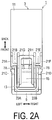
- the right side view and the left side view are symmetric) are oriented is defined as rightward, the direction in which portions of the connector fixture in the plan view (see FIG. 2A ) are oriented is defined as upward, and the direction in which portions of the connector fixture in the bottom view (see FIG. 2B ) are oriented is defined as downward.
- the left-right direction in the present embodiment corresponds to the x-axis direction in the present disclosure
- the front-back direction in the present embodiment corresponds to the y-axis direction in the present disclosure
- the up-down direction in the present embodiment corresponds to the z-axis direction.
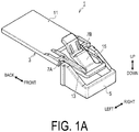
- the connector fixture 1 includes a fixture body 3 and a positioning member 5.
- the fixture body 3 and the positioning member 5 are coupled to each other via a first coupling portion 7A and a second coupling portion 7B (the first coupling portion 7A and the second coupling portion 7B correspond to an example of a connecting portion in the present disclosure).
- the portions constituting the connector fixture 1 are integrally molded of a resin material.
- the fixture body 3 includes a fixing portion 11, a support portion 13, a retaining portion 15, a first contact portion 17A, and a second contact portion 17B (the first contact portion 17A and the second contact portion 17B correspond to an example of a contact portion in the present disclosure).
- the fixing portion 11 is configured as a flat plate having a thickness in the up-down direction.
- the support portion 13 protrudes forward from a front end of the fixing portion 11.
- the first contact portion 17A and the second contact portion 17B are provided below the support portion 13.
- the retaining portion 15 extends obliquely upward and rearward from the vicinity of a front end of the support portion 13.
- the retaining portion 15 has a front end connected to the support portion 13 as a fixed end, and a rear end as a free end, and is supported such that the free end is swingable about the fixed end in the up-down direction.
- ribs 21A, 21B, 21C, 21D, 21E, and 21F are provided above the fixing portion 11 and the support portion 13.
- ribs 21G and 21H are provided above the retaining portion 15.
- ribs 211 and 21J are provided below the retaining portion 15. These ribs 21A to 21J enhance the bending rigidity of the places where the ribs 21A to 21J are provided.
- the positioning member 5 includes a first wall face 23A and a second wall face 23B, which are opposed to each other with a space therebetween in the left-right direction.
- the first coupling portion 7A and the second coupling portion 7B are tapered from one ends coupled to the positioning member 5 to the other ends coupled to the fixture body 3.
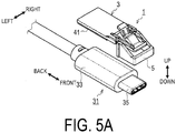
- the connector fixture 1 thus configured is attached to a first connector 31 as illustrated in FIGS. 5A , 5B , and 5C .
- the first connector 31 is a plug connector conforming to Type-C of the USB (Universal Serial Bus).
- the first connector 31 includes a resin housing portion 33 and a metallic connecting portion 35 protruding from the housing portion 33.
- both the fixture body 3 and the positioning member 5 are attached to the first connector 31.
- the fixing portion 11 is fixed to the housing portion 33 of the first connector 31.
- a double-sided tape 41 is adhered to the fixing portion 11. The double-sided tape 41 can fix the fixing portion 11 to the housing portion 33 of the first connector 31.
- the relative position between the fixture body 3 and the first connector 31 is determined. Specifically, in the left-right direction, the relative position between the fixture body 3 and the first connector 31 is determined by fitting the connecting portion 35 of the first connector 31 into the positioning member 5 as illustrated in FIG. 6A .
- the connecting portion 35 of the first connector 31 is fitted into the positioning member 5, in the state where the first wall face 23A and the second wall face 23B are disposed with a space therebetween in the direction that is parallel to the left-right direction, and the connecting portion 35 protrudes in the direction that is parallel to the front-back direction, both ends of the connecting portion 35 in the left-right direction are sandwiched between the first wall face 23A and the second wall face 23B.
- the connecting portion 35 of the first connector 31 is shaped and dimensioned in conformity with the standard. Accordingly, unlike the housing portion 33 having indefinite shape and dimension, the connecting portion 35 can be tightly fitted between the first wall face 23A and the second wall face 23B of the positioning member 5. Further, since the connecting portion 35 of the first connector 31 is made of metal, the dimensional accuracy of the connecting portion 35 is higher than that of the resin housing portion 33. Therefore, the connecting portion 35 can be fitted into the positioning member 5, achieving positioning in the left-right direction with high accuracy.
- the relative position between the fixture body 3 and the first connector 31 can be determined by causing a first contact portion 17A and the second contact portion 17B to contact the front end of the housing portion 33 (see FIG. 6B .
- FIG. 6B illustrates the second contact portion 17B).
- the connector fixture 1 is attached to the first connector 31 as described above, and then, the positioning member 5 is separated from the fixture body 3 to detach the positioning member 5. Thereby, as illustrated in FIG. 5C , only the fixture body 3 remains in the first connector 31.
- the positioning member 5 can be separated from the fixture body 3 by swinging the positioning member 5 to break the first coupling portion 7A and the second coupling portion 7B.
- the first coupling portion 7A and the second coupling portion 7B become the thinnest and weakest at the places coupled to the fixture body 3.
- the first coupling portion 7A and the second coupling portion 7B are disposed at two respective places that are spaced in the left-right direction. Therefore, when an external force is applied to the positioning member 5, the first coupling portion 7A and the second coupling portion 7B are bent at the weakest places, and as a result, the positioning member 5 swings about the axis that is parallel to the left-right direction.
- the positioning member 5 swings one or more times, a load is applied to the weakest places of the first coupling portion 7A and the second coupling portion 7B, breaking the first coupling portion 7A and the second coupling portion 7B at said places.
- the connecting portion 35 of the first connector 31 is disposed between the first wall face 23A and the second wall face 23B of the positioning member 5, but the positioning member 5 swings about the axis that is parallel to the left-right direction and thus, the swinging of the positioning member 5 is not hindered by the connecting portion 35. Further, since the positioning member 5 is less likely to swing about the axis that is parallel to the up-down direction or the front-back direction, the positioning accuracy in the left-right direction can be improved.
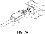
- a second connector 51 is a receptacle connector that conforms to Type-C of the USB.
- the second connector 51 is mounted on an electronic circuit board 53.
- the electronic circuit board 53 is disposed inside a panel 55 that constitutes the exterior of a device including the second connector 51.
- the panel 55 has an opening 57.
- the second connector 51 is fitted into a part of the opening 57.
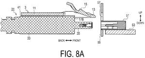
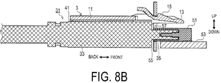
- the free end (the rear end in the figure) of the retaining portion 15 is pressed downward in the figure. This can release the retaining portion 15 hooked on the panel 55, thereby pulling out the first connector 31 and the fixture body 3 from the position illustrated in FIG. 8B to the position illustrated in FIG. 8A .
- the fixture body 3 can be attached to the first connector 31 by fixing the fixing portion 11 to the first connector 31.
- the retaining portion 15 is caught on the panel 55 of the device including the second connector 51, and prevents the first connector 31 from being displaced and detached from the second connector 51. Therefore, use of the fixture body 3 can prevent the first connector 31 from being detached from the second connector 51.
- the relative position between the fixture body 3 and the first connector 31 can be determined in the left-right direction by the positioning member 5, in the front-back direction by the first contact portion 17A and the second contact portion 17B, and in the up-down direction by the fixing portion 11. Accordingly, as compared with the case where positioning cannot be performed in any one or more of the left-right direction, the front-back direction, and the up-down direction, the fixture body 3 can be accurately positioned and attached to the first connector 31.
- the positioning member 5 can be detached by separating the positioning member 5 from the fixture body 3 in the state where the fixing portion 11 is fixed to the first connector 31.
- the structure attached to the first connector 31 can be made compact.
- the positioning member 5 does not get in the way. Therefore, even the positioning member 5 that would become an obstacle when the first connector 31 is connected to the second connector 51 unless detached may be used without any problem.
- the exemplary embodiment has been used to describe the connector fixture 1, but should not be construed to be any more than an example of one aspect of the present disclosure.
- the present disclosure is not limited to the exemplary embodiment described above and can be embodied in various forms without departing from the technical concept of the present disclosure.
- the fixing portion 11 is configured to be fixed to the first connector 31 with the double-sided tape 41.
- the fixing portion 11 may be configured to be fixed to the first connector 31 with fixing means other than the double-sided tape 41.
- an adhesive may be used in place of the double-sided tape 41.
- the housing portion 33 of the first connector 31 can be designed specifically for the connector fixture 1, the fixing portion 11 and the housing portion 33 of the first connector 31 may be provided with mutually engageable engaging mechanisms.
- the fixture body 3 and the first connector 31 are positioned in the left-right direction by the positioning member 5 and however, may be also positioned in the up-down direction and the front-back direction by the positioning member 5.
- a convex portion 61 that fits into the connecting portion 35 of the first connector 31 can be provided on the positioning member 5, and the first fixture body 3 and the first connector 31 can be positioned in the up-down direction and the front-back direction by the convex portion 61.
- first contact portion 17A and the second contact portion 17B are described as an example of the contact portion in the present disclosure.
- the number of the contact portion is not limited to two, and may be one or three or more.
- the plug connector and the receptacle connector that conform to Type-C of the USB are exemplified as examples of the first connector and the second connector in the present disclosure.
- these connectors may be any other form of connector.
- a function realized by a single constituent element in each the above-described embodiments may instead be realized by a plurality of constituent elements. Additionally, a function realized by a plurality of constituent elements may instead be realized by a single constituent element. Parts of the configurations in the above-described embodiments may be omitted. At least part of the configuration of one of the above-described embodiments may be added to or replace the configuration of another of the above-described embodiments.
- the connector fixture of the present disclosure may be further provided with configurations such as those given below.
- the first connector may include a housing portion and a metal connecting portion protruding from the housing portion, and when the connecting portion is connected to the second connector, the connecting portion may be inserted into the second connector.
- the positioning member may be configured to contact the connecting portion when the fixture body is attached to the first connector, to determine relative position between the fixture body and the first connector in the x-axis direction.
- the positioning member may have two wall faces opposed to each other with a space therebetween, and in the state where the two wall faces are disposed with the space in the direction that is parallel to the x-axis direction and the connecting portion protrudes in the direction that is parallel to the y-axis direction, the positioning member is configured to sandwich both ends of the connecting portion in the x-axis direction between the two wall faces to determine relative position between the fixture body and the first connector in the x-axis direction.
- the positioning member may be configured to be swingably coupled to the fixture body via at least one coupling portion integrally molded with the fixture body and the positioning member using a resin material, to swing the positioning member to break the coupling portion, being separable from the fixture body.
- a first coupling portion and a second coupling portion may be provided as at least one coupling portion.
- the first coupling portion and the second coupling portion may be disposed with a space therebetween in the x-axis direction such that the swinging center of the positioning member is parallel to the x-axis direction.
Landscapes
- Engineering & Computer Science (AREA)
- Manufacturing & Machinery (AREA)
- Details Of Connecting Devices For Male And Female Coupling (AREA)
Applications Claiming Priority (1)
| Application Number | Priority Date | Filing Date | Title |
|---|---|---|---|
| JP2018200072A JP7014424B2 (ja) | 2018-10-24 | 2018-10-24 | コネクタ固定具 |
Publications (2)
| Publication Number | Publication Date |
|---|---|
| EP3644453A1 true EP3644453A1 (fr) | 2020-04-29 |
| EP3644453B1 EP3644453B1 (fr) | 2022-02-09 |
Family
ID=68342751
Family Applications (1)
| Application Number | Title | Priority Date | Filing Date |
|---|---|---|---|
| EP19205007.8A Active EP3644453B1 (fr) | 2018-10-24 | 2019-10-24 | Accessoire de connecteur |
Country Status (3)
| Country | Link |
|---|---|
| US (1) | US10916886B2 (fr) |
| EP (1) | EP3644453B1 (fr) |
| JP (1) | JP7014424B2 (fr) |
Families Citing this family (2)
| Publication number | Priority date | Publication date | Assignee | Title |
|---|---|---|---|---|
| JP6255190B2 (ja) * | 2013-08-30 | 2017-12-27 | ダンロップスポーツ株式会社 | アイアン型ゴルフクラブヘッド、及びこれを備えたゴルフクラブセット |
| JP7522588B2 (ja) * | 2020-06-09 | 2024-07-25 | 日本航空電子工業株式会社 | ロケータ、ハーネス及びハーネスの製造方法 |
Citations (4)
| Publication number | Priority date | Publication date | Assignee | Title |
|---|---|---|---|---|
| JPH02108276U (fr) * | 1989-02-16 | 1990-08-28 | ||
| JP2005142127A (ja) | 2003-11-10 | 2005-06-02 | Nec Corp | ロック爪代替用冶具 |
| WO2010047345A1 (fr) * | 2008-10-21 | 2010-04-29 | 木谷電器株式会社 | Dispositif de connecteur approprié pour connecter des câbles électriques entre eux et utilisé dans un système de production d’énergie électrique à énergie solaire |
| WO2017086259A1 (fr) * | 2015-11-20 | 2017-05-26 | 北川工業株式会社 | Accessoire de connecteur |
Family Cites Families (11)
| Publication number | Priority date | Publication date | Assignee | Title |
|---|---|---|---|---|
| JP3064910U (ja) * | 1999-06-15 | 2000-01-28 | アイコム株式会社 | モジュラコネクタ用のプラグの補修具 |
| JP2001345140A (ja) * | 2000-05-31 | 2001-12-14 | Yazaki Corp | リヤホルダ付きコネクタおよびその仮係止装置 |
| JP2005142147A (ja) * | 2003-10-15 | 2005-06-02 | Alps Electric Co Ltd | 熱応動スイッチ及びその製造方法 |
| JP2005332671A (ja) * | 2004-05-19 | 2005-12-02 | Internatl Business Mach Corp <Ibm> | コネクタ用プラグラッチ、および破損プラグに対するラッチ機能の復元方法 |
| JP4883726B2 (ja) * | 2009-05-11 | 2012-02-22 | ヒロセ電機株式会社 | モジュラープラグ |
| CN101901991A (zh) * | 2009-05-27 | 2010-12-01 | 鸿富锦精密工业(深圳)有限公司 | 水晶头及其卡扣装置 |
| CA3033380A1 (fr) * | 2011-12-09 | 2013-06-09 | Mercury Plastics Llc | Accouplement de tube a connexion rapide |
| US10048447B2 (en) * | 2013-10-31 | 2018-08-14 | CommScope Connectivity Belgium BVBA | Fiber optic connection system |
| US9913401B2 (en) * | 2014-05-29 | 2018-03-06 | Arris Enterprises Llc | Pivotable fan assembly and associated systems |
| WO2016081973A1 (fr) * | 2014-11-24 | 2016-06-02 | Milner Wayne Russell | Pièce de montage d'une pièce de raccordement |
| JP6818418B2 (ja) * | 2016-02-26 | 2021-01-20 | ヒロセ電機株式会社 | シェルを有するコネクタ及びコネクタ装置 |
-
2018
- 2018-10-24 JP JP2018200072A patent/JP7014424B2/ja active Active
-
2019
- 2019-10-23 US US16/661,257 patent/US10916886B2/en active Active
- 2019-10-24 EP EP19205007.8A patent/EP3644453B1/fr active Active
Patent Citations (4)
| Publication number | Priority date | Publication date | Assignee | Title |
|---|---|---|---|---|
| JPH02108276U (fr) * | 1989-02-16 | 1990-08-28 | ||
| JP2005142127A (ja) | 2003-11-10 | 2005-06-02 | Nec Corp | ロック爪代替用冶具 |
| WO2010047345A1 (fr) * | 2008-10-21 | 2010-04-29 | 木谷電器株式会社 | Dispositif de connecteur approprié pour connecter des câbles électriques entre eux et utilisé dans un système de production d’énergie électrique à énergie solaire |
| WO2017086259A1 (fr) * | 2015-11-20 | 2017-05-26 | 北川工業株式会社 | Accessoire de connecteur |
Also Published As
| Publication number | Publication date |
|---|---|
| JP7014424B2 (ja) | 2022-02-01 |
| EP3644453B1 (fr) | 2022-02-09 |
| US10916886B2 (en) | 2021-02-09 |
| US20200194933A1 (en) | 2020-06-18 |
| JP2020068115A (ja) | 2020-04-30 |
Similar Documents
| Publication | Publication Date | Title |
|---|---|---|
| CN109904648B (zh) | 连接器以及连接器组件 | |
| EP2958198B1 (fr) | Dispositif de câblage comprenant un boîtier et un circuit imprimé | |
| CN108075295B (zh) | 连接器和复合连接器 | |
| JP2014154802A (ja) | Usbコンセント | |
| JP4726737B2 (ja) | 光コネクタの抜け止め解除補助装置およびプリント基板装置 | |
| JP2020061227A (ja) | コネクタ組立体 | |
| EP3644453B1 (fr) | Accessoire de connecteur | |
| JP7769994B2 (ja) | Usbコンセント | |
| US20060166544A1 (en) | Connector assembly | |
| JP6210773B2 (ja) | フラットケーブル用コネクタ | |
| JP6890275B2 (ja) | Usbコンセント | |
| JP2019129137A (ja) | コネクタ、相手方コネクタ及びコネクタ組立体 | |
| JP6782448B2 (ja) | Usbコンセント | |
| JP7068252B2 (ja) | 電気接続箱ユニット | |
| JP2021022475A (ja) | コネクタ | |
| JP6837205B2 (ja) | Usbコンセント | |
| CN104685396B (zh) | 壳体连接结构 | |
| CN103378462A (zh) | 连接器 | |
| KR20110014270A (ko) | 편평케이블용 플러그 커넥터 | |
| CN223297080U (zh) | 解锁弹片以及电连接器 | |
| JP6089381B2 (ja) | Usbコンセント | |
| JP4403951B2 (ja) | 電子機器 | |
| JP6731647B2 (ja) | Usbコンセント | |
| JP6811413B2 (ja) | Usbコンセント | |
| JP2007123035A (ja) | パネル取付用コネクタ |
Legal Events
| Date | Code | Title | Description |
|---|---|---|---|
| PUAI | Public reference made under article 153(3) epc to a published international application that has entered the european phase |
Free format text: ORIGINAL CODE: 0009012 |
|
| STAA | Information on the status of an ep patent application or granted ep patent |
Free format text: STATUS: REQUEST FOR EXAMINATION WAS MADE |
|
| 17P | Request for examination filed |
Effective date: 20191024 |
|
| AK | Designated contracting states |
Kind code of ref document: A1 Designated state(s): AL AT BE BG CH CY CZ DE DK EE ES FI FR GB GR HR HU IE IS IT LI LT LU LV MC MK MT NL NO PL PT RO RS SE SI SK SM TR |
|
| AX | Request for extension of the european patent |
Extension state: BA ME |
|
| GRAP | Despatch of communication of intention to grant a patent |
Free format text: ORIGINAL CODE: EPIDOSNIGR1 |
|
| STAA | Information on the status of an ep patent application or granted ep patent |
Free format text: STATUS: GRANT OF PATENT IS INTENDED |
|
| INTG | Intention to grant announced |
Effective date: 20211001 |
|
| GRAS | Grant fee paid |
Free format text: ORIGINAL CODE: EPIDOSNIGR3 |
|
| GRAA | (expected) grant |
Free format text: ORIGINAL CODE: 0009210 |
|
| STAA | Information on the status of an ep patent application or granted ep patent |
Free format text: STATUS: THE PATENT HAS BEEN GRANTED |
|
| AK | Designated contracting states |
Kind code of ref document: B1 Designated state(s): AL AT BE BG CH CY CZ DE DK EE ES FI FR GB GR HR HU IE IS IT LI LT LU LV MC MK MT NL NO PL PT RO RS SE SI SK SM TR |
|
| REG | Reference to a national code |
Ref country code: GB Ref legal event code: FG4D |
|
| REG | Reference to a national code |
Ref country code: CH Ref legal event code: EP Ref country code: AT Ref legal event code: REF Ref document number: 1468074 Country of ref document: AT Kind code of ref document: T Effective date: 20220215 |
|
| REG | Reference to a national code |
Ref country code: DE Ref legal event code: R096 Ref document number: 602019011457 Country of ref document: DE |
|
| REG | Reference to a national code |
Ref country code: IE Ref legal event code: FG4D |
|
| REG | Reference to a national code |
Ref country code: LT Ref legal event code: MG9D |
|
| REG | Reference to a national code |
Ref country code: NL Ref legal event code: MP Effective date: 20220209 |
|
| REG | Reference to a national code |
Ref country code: AT Ref legal event code: MK05 Ref document number: 1468074 Country of ref document: AT Kind code of ref document: T Effective date: 20220209 |
|
| PG25 | Lapsed in a contracting state [announced via postgrant information from national office to epo] |
Ref country code: SE Free format text: LAPSE BECAUSE OF FAILURE TO SUBMIT A TRANSLATION OF THE DESCRIPTION OR TO PAY THE FEE WITHIN THE PRESCRIBED TIME-LIMIT Effective date: 20220209 Ref country code: RS Free format text: LAPSE BECAUSE OF FAILURE TO SUBMIT A TRANSLATION OF THE DESCRIPTION OR TO PAY THE FEE WITHIN THE PRESCRIBED TIME-LIMIT Effective date: 20220209 Ref country code: PT Free format text: LAPSE BECAUSE OF FAILURE TO SUBMIT A TRANSLATION OF THE DESCRIPTION OR TO PAY THE FEE WITHIN THE PRESCRIBED TIME-LIMIT Effective date: 20220609 Ref country code: NO Free format text: LAPSE BECAUSE OF FAILURE TO SUBMIT A TRANSLATION OF THE DESCRIPTION OR TO PAY THE FEE WITHIN THE PRESCRIBED TIME-LIMIT Effective date: 20220509 Ref country code: NL Free format text: LAPSE BECAUSE OF FAILURE TO SUBMIT A TRANSLATION OF THE DESCRIPTION OR TO PAY THE FEE WITHIN THE PRESCRIBED TIME-LIMIT Effective date: 20220209 Ref country code: LT Free format text: LAPSE BECAUSE OF FAILURE TO SUBMIT A TRANSLATION OF THE DESCRIPTION OR TO PAY THE FEE WITHIN THE PRESCRIBED TIME-LIMIT Effective date: 20220209 Ref country code: HR Free format text: LAPSE BECAUSE OF FAILURE TO SUBMIT A TRANSLATION OF THE DESCRIPTION OR TO PAY THE FEE WITHIN THE PRESCRIBED TIME-LIMIT Effective date: 20220209 Ref country code: ES Free format text: LAPSE BECAUSE OF FAILURE TO SUBMIT A TRANSLATION OF THE DESCRIPTION OR TO PAY THE FEE WITHIN THE PRESCRIBED TIME-LIMIT Effective date: 20220209 Ref country code: BG Free format text: LAPSE BECAUSE OF FAILURE TO SUBMIT A TRANSLATION OF THE DESCRIPTION OR TO PAY THE FEE WITHIN THE PRESCRIBED TIME-LIMIT Effective date: 20220509 |
|
| PG25 | Lapsed in a contracting state [announced via postgrant information from national office to epo] |
Ref country code: PL Free format text: LAPSE BECAUSE OF FAILURE TO SUBMIT A TRANSLATION OF THE DESCRIPTION OR TO PAY THE FEE WITHIN THE PRESCRIBED TIME-LIMIT Effective date: 20220209 Ref country code: LV Free format text: LAPSE BECAUSE OF FAILURE TO SUBMIT A TRANSLATION OF THE DESCRIPTION OR TO PAY THE FEE WITHIN THE PRESCRIBED TIME-LIMIT Effective date: 20220209 Ref country code: GR Free format text: LAPSE BECAUSE OF FAILURE TO SUBMIT A TRANSLATION OF THE DESCRIPTION OR TO PAY THE FEE WITHIN THE PRESCRIBED TIME-LIMIT Effective date: 20220510 Ref country code: FI Free format text: LAPSE BECAUSE OF FAILURE TO SUBMIT A TRANSLATION OF THE DESCRIPTION OR TO PAY THE FEE WITHIN THE PRESCRIBED TIME-LIMIT Effective date: 20220209 Ref country code: AT Free format text: LAPSE BECAUSE OF FAILURE TO SUBMIT A TRANSLATION OF THE DESCRIPTION OR TO PAY THE FEE WITHIN THE PRESCRIBED TIME-LIMIT Effective date: 20220209 |
|
| PG25 | Lapsed in a contracting state [announced via postgrant information from national office to epo] |
Ref country code: IS Free format text: LAPSE BECAUSE OF FAILURE TO SUBMIT A TRANSLATION OF THE DESCRIPTION OR TO PAY THE FEE WITHIN THE PRESCRIBED TIME-LIMIT Effective date: 20220609 |
|
| PG25 | Lapsed in a contracting state [announced via postgrant information from national office to epo] |
Ref country code: SM Free format text: LAPSE BECAUSE OF FAILURE TO SUBMIT A TRANSLATION OF THE DESCRIPTION OR TO PAY THE FEE WITHIN THE PRESCRIBED TIME-LIMIT Effective date: 20220209 Ref country code: SK Free format text: LAPSE BECAUSE OF FAILURE TO SUBMIT A TRANSLATION OF THE DESCRIPTION OR TO PAY THE FEE WITHIN THE PRESCRIBED TIME-LIMIT Effective date: 20220209 Ref country code: RO Free format text: LAPSE BECAUSE OF FAILURE TO SUBMIT A TRANSLATION OF THE DESCRIPTION OR TO PAY THE FEE WITHIN THE PRESCRIBED TIME-LIMIT Effective date: 20220209 Ref country code: EE Free format text: LAPSE BECAUSE OF FAILURE TO SUBMIT A TRANSLATION OF THE DESCRIPTION OR TO PAY THE FEE WITHIN THE PRESCRIBED TIME-LIMIT Effective date: 20220209 Ref country code: DK Free format text: LAPSE BECAUSE OF FAILURE TO SUBMIT A TRANSLATION OF THE DESCRIPTION OR TO PAY THE FEE WITHIN THE PRESCRIBED TIME-LIMIT Effective date: 20220209 Ref country code: CZ Free format text: LAPSE BECAUSE OF FAILURE TO SUBMIT A TRANSLATION OF THE DESCRIPTION OR TO PAY THE FEE WITHIN THE PRESCRIBED TIME-LIMIT Effective date: 20220209 |
|
| REG | Reference to a national code |
Ref country code: DE Ref legal event code: R097 Ref document number: 602019011457 Country of ref document: DE |
|
| PG25 | Lapsed in a contracting state [announced via postgrant information from national office to epo] |
Ref country code: AL Free format text: LAPSE BECAUSE OF FAILURE TO SUBMIT A TRANSLATION OF THE DESCRIPTION OR TO PAY THE FEE WITHIN THE PRESCRIBED TIME-LIMIT Effective date: 20220209 |
|
| PLBE | No opposition filed within time limit |
Free format text: ORIGINAL CODE: 0009261 |
|
| STAA | Information on the status of an ep patent application or granted ep patent |
Free format text: STATUS: NO OPPOSITION FILED WITHIN TIME LIMIT |
|
| 26N | No opposition filed |
Effective date: 20221110 |
|
| PG25 | Lapsed in a contracting state [announced via postgrant information from national office to epo] |
Ref country code: SI Free format text: LAPSE BECAUSE OF FAILURE TO SUBMIT A TRANSLATION OF THE DESCRIPTION OR TO PAY THE FEE WITHIN THE PRESCRIBED TIME-LIMIT Effective date: 20220209 |
|
| PG25 | Lapsed in a contracting state [announced via postgrant information from national office to epo] |
Ref country code: MC Free format text: LAPSE BECAUSE OF FAILURE TO SUBMIT A TRANSLATION OF THE DESCRIPTION OR TO PAY THE FEE WITHIN THE PRESCRIBED TIME-LIMIT Effective date: 20220209 |
|
| REG | Reference to a national code |
Ref country code: CH Ref legal event code: PL |
|
| REG | Reference to a national code |
Ref country code: BE Ref legal event code: MM Effective date: 20221031 |
|
| PG25 | Lapsed in a contracting state [announced via postgrant information from national office to epo] |
Ref country code: LU Free format text: LAPSE BECAUSE OF NON-PAYMENT OF DUE FEES Effective date: 20221024 |
|
| PG25 | Lapsed in a contracting state [announced via postgrant information from national office to epo] |
Ref country code: LI Free format text: LAPSE BECAUSE OF NON-PAYMENT OF DUE FEES Effective date: 20221031 Ref country code: IT Free format text: LAPSE BECAUSE OF FAILURE TO SUBMIT A TRANSLATION OF THE DESCRIPTION OR TO PAY THE FEE WITHIN THE PRESCRIBED TIME-LIMIT Effective date: 20220209 Ref country code: FR Free format text: LAPSE BECAUSE OF NON-PAYMENT OF DUE FEES Effective date: 20221031 Ref country code: CH Free format text: LAPSE BECAUSE OF NON-PAYMENT OF DUE FEES Effective date: 20221031 |
|
| PG25 | Lapsed in a contracting state [announced via postgrant information from national office to epo] |
Ref country code: BE Free format text: LAPSE BECAUSE OF NON-PAYMENT OF DUE FEES Effective date: 20221031 |
|
| PG25 | Lapsed in a contracting state [announced via postgrant information from national office to epo] |
Ref country code: IE Free format text: LAPSE BECAUSE OF NON-PAYMENT OF DUE FEES Effective date: 20221024 |
|
| PG25 | Lapsed in a contracting state [announced via postgrant information from national office to epo] |
Ref country code: HU Free format text: LAPSE BECAUSE OF FAILURE TO SUBMIT A TRANSLATION OF THE DESCRIPTION OR TO PAY THE FEE WITHIN THE PRESCRIBED TIME-LIMIT; INVALID AB INITIO Effective date: 20191024 |
|
| PG25 | Lapsed in a contracting state [announced via postgrant information from national office to epo] |
Ref country code: CY Free format text: LAPSE BECAUSE OF FAILURE TO SUBMIT A TRANSLATION OF THE DESCRIPTION OR TO PAY THE FEE WITHIN THE PRESCRIBED TIME-LIMIT Effective date: 20220209 |
|
| PG25 | Lapsed in a contracting state [announced via postgrant information from national office to epo] |
Ref country code: MK Free format text: LAPSE BECAUSE OF FAILURE TO SUBMIT A TRANSLATION OF THE DESCRIPTION OR TO PAY THE FEE WITHIN THE PRESCRIBED TIME-LIMIT Effective date: 20220209 |
|
| GBPC | Gb: european patent ceased through non-payment of renewal fee |
Effective date: 20231024 |
|
| PG25 | Lapsed in a contracting state [announced via postgrant information from national office to epo] |
Ref country code: GB Free format text: LAPSE BECAUSE OF NON-PAYMENT OF DUE FEES Effective date: 20231024 |
|
| PG25 | Lapsed in a contracting state [announced via postgrant information from national office to epo] |
Ref country code: GB Free format text: LAPSE BECAUSE OF NON-PAYMENT OF DUE FEES Effective date: 20231024 |
|
| PG25 | Lapsed in a contracting state [announced via postgrant information from national office to epo] |
Ref country code: MT Free format text: LAPSE BECAUSE OF FAILURE TO SUBMIT A TRANSLATION OF THE DESCRIPTION OR TO PAY THE FEE WITHIN THE PRESCRIBED TIME-LIMIT Effective date: 20220209 |
|
| PG25 | Lapsed in a contracting state [announced via postgrant information from national office to epo] |
Ref country code: TR Free format text: LAPSE BECAUSE OF FAILURE TO SUBMIT A TRANSLATION OF THE DESCRIPTION OR TO PAY THE FEE WITHIN THE PRESCRIBED TIME-LIMIT Effective date: 20220209 |
|
| PGFP | Annual fee paid to national office [announced via postgrant information from national office to epo] |
Ref country code: DE Payment date: 20251021 Year of fee payment: 7 |