EP3644476A1 - Moteur et compresseur - Google Patents
Moteur et compresseur Download PDFInfo
- Publication number
- EP3644476A1 EP3644476A1 EP18850551.5A EP18850551A EP3644476A1 EP 3644476 A1 EP3644476 A1 EP 3644476A1 EP 18850551 A EP18850551 A EP 18850551A EP 3644476 A1 EP3644476 A1 EP 3644476A1
- Authority
- EP
- European Patent Office
- Prior art keywords
- motor
- electric motor
- coil
- stator
- lead
- Prior art date
- Legal status (The legal status is an assumption and is not a legal conclusion. Google has not performed a legal analysis and makes no representation as to the accuracy of the status listed.)
- Granted
Links
Images


Classifications
-
- H—ELECTRICITY
- H02—GENERATION; CONVERSION OR DISTRIBUTION OF ELECTRIC POWER
- H02K—DYNAMO-ELECTRIC MACHINES
- H02K3/00—Details of windings
- H02K3/04—Windings characterised by the conductor shape, form or construction, e.g. with bar conductors
- H02K3/28—Layout of windings or of connections between windings
-
- H—ELECTRICITY
- H02—GENERATION; CONVERSION OR DISTRIBUTION OF ELECTRIC POWER
- H02K—DYNAMO-ELECTRIC MACHINES
- H02K1/00—Details of the magnetic circuit
- H02K1/06—Details of the magnetic circuit characterised by the shape, form or construction
- H02K1/12—Stationary parts of the magnetic circuit
- H02K1/16—Stator cores with slots for windings
-
- H—ELECTRICITY
- H02—GENERATION; CONVERSION OR DISTRIBUTION OF ELECTRIC POWER
- H02K—DYNAMO-ELECTRIC MACHINES
- H02K1/00—Details of the magnetic circuit
- H02K1/06—Details of the magnetic circuit characterised by the shape, form or construction
- H02K1/22—Rotating parts of the magnetic circuit
- H02K1/27—Rotor cores with permanent magnets
- H02K1/2706—Inner rotors
-
- H—ELECTRICITY
- H02—GENERATION; CONVERSION OR DISTRIBUTION OF ELECTRIC POWER
- H02K—DYNAMO-ELECTRIC MACHINES
- H02K15/00—Processes or apparatus specially adapted for manufacturing, assembling, maintaining or repairing of dynamo-electric machines
- H02K15/30—Manufacture of winding connections
- H02K15/32—Manufacture of terminal arrangements; Connecting the terminals to external circuits
-
- H—ELECTRICITY
- H02—GENERATION; CONVERSION OR DISTRIBUTION OF ELECTRIC POWER
- H02K—DYNAMO-ELECTRIC MACHINES
- H02K15/00—Processes or apparatus specially adapted for manufacturing, assembling, maintaining or repairing of dynamo-electric machines
- H02K15/30—Manufacture of winding connections
- H02K15/33—Connecting winding sections; Forming leads; Connecting leads to terminals
-
- H—ELECTRICITY
- H02—GENERATION; CONVERSION OR DISTRIBUTION OF ELECTRIC POWER
- H02K—DYNAMO-ELECTRIC MACHINES
- H02K3/00—Details of windings
- H02K3/46—Fastening of windings on the stator or rotor structure
- H02K3/52—Fastening salient pole windings or connections thereto
- H02K3/521—Fastening salient pole windings or connections thereto applicable to stators only
- H02K3/522—Fastening salient pole windings or connections thereto applicable to stators only for generally annular cores with salient poles
-
- H—ELECTRICITY
- H02—GENERATION; CONVERSION OR DISTRIBUTION OF ELECTRIC POWER
- H02K—DYNAMO-ELECTRIC MACHINES
- H02K2203/00—Specific aspects not provided for in the other groups of this subclass relating to the windings
- H02K2203/06—Machines characterised by the wiring leads, i.e. conducting wires for connecting the winding terminations
-
- H—ELECTRICITY
- H02—GENERATION; CONVERSION OR DISTRIBUTION OF ELECTRIC POWER
- H02K—DYNAMO-ELECTRIC MACHINES
- H02K2213/00—Specific aspects, not otherwise provided for and not covered by codes H02K2201/00 - H02K2211/00
- H02K2213/03—Machines characterised by numerical values, ranges, mathematical expressions or similar information
Definitions
- the present disclosure relates to the technical field of compressor, in particular to an electric motor and a compressor.
- the speed of the motor can only be adjusted within a small range of 30 rps to 90 rps. If the speed is forced up, the motor would enter the weak magnetic zone, which causing a rapid rise in coil current and a significant increase in temperature. As such the electric motor lines is degraded, and the reliability and performance of the electric motor are affected.
- an exemplary method is to inject a negative direct axis current to the coil group of the motor to demagnetize the permanent magnet. Therefore, the back electromotive force is reduced, and the operating range of the electric motor is enlarged.
- the above method would result in a lower efficiency of the motor, when the motor is running at a high frequency.
- the main objective of the present disclosure is to provide an electric motor with a high working efficiency.
- an electric motor including an motor stator and an motor rotor
- the motor stator includes:
- the electric motor satisfies a relationship: 5.18 ⁇ 10 -7 ⁇ T ⁇ Di -3 ⁇ TPV -1 ⁇ 1.17 ⁇ 10 -6 ;
- T is a rated torque of the electric motor with a unit of N ⁇ m;
- Di is a minimum inner diameter of the stator core with a unit of mm;
- TPV is a torque per unit volume of the motor rotor with a unit of kN ⁇ m ⁇ m -3 , and TPV is greater than or equal to 5kN ⁇ m ⁇ m -3 , and less than or equal to 45kN ⁇ m ⁇ m -3 .
- the motor stator further includes a plurality of plug connectors, and the plurality of the motor leads of each motor lead group are connected with the motor control circuit through at least one plug connector.
- the number of the plug connectors is two, and the plurality of motor leads of each the motor lead group are connected with the motor control circuit by one plug connector.
- the number of plug connectors is corresponding to the number of the plurality of motor leads; and each of the plug connectors is connected to each corresponding motor lead.
- each of the coil groups include 2n coil ends, and n is a positive integer; and the 2n coil ends include n incoming line ends configured to form the incoming line terminal and n outgoing line ends configured to form the outgoing line terminal; one of the plug connectors is connected to one motor lead connected with the n incoming line ends, and the other one is connected to another electric motor lead connected with the n outgoing line ends.
- the number of coil groups is three, each coil group includes one incoming line end and one outgoing line end.
- the electric motor includes a first line connection state and a second line connection state, a back electromotive force coefficient of the electric motor is ke1, in response to the first line connection state; the back electromotive force coefficient of the electric motor is ke2, in response to the second line connection state; ke1 is greater than 45V/krpmm, and a result of dividing ke1 by ke2 is greater than or equal to1.6 and lesser than or equal to 1.8.
- a rated rotating speed of the electric motor is greater than or equal to 6000 rpm.
- a maximum rotating speed of the electric motor is greater than or equal to 9000 rpm.
- the present disclosure also provides a compressor including an electric motor as described above.
- the electric motor includes an motor stator and an motor rotor, the motor stator includes:
- each motor lead of two motor lead groups which is connected with the motor control circuit and the plurality of coil groups, is electrically connected with one coil end of one coil group. So that the motor control circuit can be configured to switch line connecting modes of the coil groups of the electrical motor according to different operating conditions of the electric motor. Thus the working efficiency of the electric motor is improved.
- the descriptions, such as the "first”, the “second” in the present disclosure, can only be used for describing the aim of description, and cannot be understood as indicating or suggestting relative importance or impliedly indicating the number of the indicated technical character. Therefore, the character indicated by the "first”, the “second” can express or impliedly include at least one character.
- the technical proposal of each exemplary embodiment can be combined with each other, however the technical proposal must base on that the ordinary skill in that art can realize the technical proposal, when the combination of the technical proposals occurs contradiction or cannot realize, it should consider that the combination of the technical proposals does not existed, and is not contained in the protection scope required by the present disclosure.
- the present disclosure provides a compressor having an electric motor.
- the electric motor can be a permanent magnet electric motor, a three-phase asynchronous electric motor, etc., which is not limited in present embodiment.
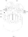
- the electric motor includes: an motor rotor 20; and an motor stator 10, the motor rotor 20 includes: a stator core 101 having a plurality of stator tooth 101b spaced along a circumferential direction of the stator core 101, two adjacent stator tooth 101b defining a stator slot 101a; a plurality of coil groups, each of the plurality of coil groups including a plurality of coils 102 wound on the stator tooth 101b, and an incoming line terminal and an outgoing line terminal both composed of a same number of coil end.
- each coil group has a plurality of coils 102.
- the coil group has two coil ends. At this time, one coil end thereof serves as the incoming line terminal of the coil group, and the other one of serves as the outgoing line terminal of the coil group.
- the number of coil ends of the coil group is an even number and greater than two. At this time, a half coil ends are configured to form the incoming line terminal of the coil group, and the other half of the coil ends are configured to form the outgoing line terminal.
- the motor stator 10 further includes two motor lead groups 103.
- Each motor lead group 103 has a plurality of motor leads 103a which are connect to the motor control circuits (not shown) and the coil ends of the coil groups. And the total number of motor leads 103a in each motor lead group 103 is equal to the number of coil groups. And each motor lead 103a is connected to one the incoming line terminal or the outgoing line terminal of one coil group.
- each motor lead 103a in each motor lead group 103 is equal to the number of coil groups.
- each motor lead 103a is connected to a line connecting terminal composed by one or more coil ends of one coil group.
- the motor control circuit can be configured to switch the line connecting modes of multiple coil groups according to the working condition of the electric motor.
- the electric motor is configured to control the multiple coil groups to switch between a line connecting mode of connecting the incoming line terminals of the multiple coil groups together and another line connecting mode of connecting the incoming line terminal of each coil group with one corresponding outgoing line terminal of another coil group, according to different operating frequencies of the electric motor. So that the work efficiencies of the electric motor at high frequency and low frequency are balanced.
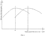
- the electric motor when the electric motor is running at a high speed, the electric motor has the highest efficiency at the rotating speed of nl. When the electric motor is running at a low speed, the electric motor has the highest efficiency at the rotating speed of n2.
- the electric motor has the first line connection state and the second line connection state by changing the line connecting mode.
- a back electromotive force coefficient of the electric motor is ke1
- the electric motor is made in the first line connection state when the electric motor is in the low speed running state.
- the electric motor is made in the second line connection state when the electric motor is in the high speed running state. So that the electric motor is prevented from entering the weak magnetic field, the required winding current is reduced when the electric motor generates the same torque, and the copper consumption is reduced. Thus the electric motor has higher efficient.
- ke1 is greater than or equal to 45 V/krpm, so that the electric motor has higher efficiency when operating at the low speed.
- a result of dividing ke1 by ke2 is greater than or equal to1.6, and lesser than or equal to 1.8, which balancing the working efficiencies of the electric motor at the high speed and the low speed and improving the overall performance of the electric motor.
- the specific values of ke1 and ke2 are determined according to the type of the electric motor. For example, the back electromotive force coefficient ke1 is 84.33 V/krpm when the electric motor is in the first line connection state. And the back electromotive force coefficient ke1 is 48.89 V/krpm when the electric motor is in the second line connection state. So that the electric motor which has high working efficiency at both the high speed and the low speed, the high speed and the low speed are matched with the compressor.
- the electric motor is enabled to run more stably and efficiently by changing the electric motor control parameters.
- the electric motor can have two sets of electric motor control parameters.
- the electric motor is controlled by different electric motor control parameters to ensure stable and efficient operation of the electric motor.
- the line connection mode of the electric motor is changed to increase the back electromotive force coefficient of the electric motor, one or more parameters of the line resistance ⁇ , the peak-to-peak value of the magnetic flux (mWb.T), and the cross-axis inductance Ld/Lq(mH) of the electric motor can be increased to ensure stable and efficient operation of the electric motor.
- other parameters of the electric motor can be controlled to change, which is not limited in present embodiment.
- the line resistance ⁇ is 7.42 ⁇
- the peak-to-peak value of the magnetic flux (mWb.T) is 75.4 mWb.T
- the cross-axis inductance Ld/Lq (mH) is 27.37mH / 41.23mH.
- the electric motor can also have a third line connection state, a fourth line connection state, etc., so that the electric motor has more different back electromotive force coefficients.
- the electric motor also has more sets of electric motor control parameters which correspond to different line connection states.
- the electric motor can be switched between different line connection states by program control mode or circuit control mode.
- the electric motor includes an electrical control board that is electrically connected to the leads of the electric motor, to control the electric motor to switch between different line connection states.
- the electric motor in order to better fit the electric motor and the compressor.
- the electric motor satisfies a relationship: 5.18 ⁇ 10 -7 ⁇ T ⁇ Di -3 ⁇ TPV -1 ⁇ 1.17 ⁇ 10 -6 .
- T is a rated torque of the electric motor with a unit of Nm.
- Di is a minimum inner diameter of the stator core 101 with a unit of mm. That is, as shown in FIG. 2 , the diameter of a circle is formed by enclosuring ends of the plurality of stator tooth 101b of the stator core 101 facing the centre line.
- TPV is a torque per unit volume of the motor rotor 20 with a unit of kN ⁇ m ⁇ m -3 , and TPV is greater than or equal to 5kN ⁇ m ⁇ m -3 , and less than or equal to 45kN ⁇ m ⁇ m -3 .
- the above electric motor can also be used in other fields, which is depending on the type and size of the electric motor.
- the motor stator 10 further includes: a plurality of plug connectors.
- the plurality of the motor leads 103a of each motor lead group 103 are connected with an motor control circuit through at least one plug connector.
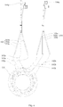
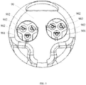
- the plug connector can adopt the structure of the plug connector 104 as shown in FIG. 1 to FIG. 3 , or the structure of the plug connector 104a as shown in FIG. 4 .
- the plug connector 104 shown in FIG. 1 to FIG. 3 is a junction box structure. And the plug connector 104 is more suitable to connect with a plurality of motor leads 103a.
- the plug connector 104a shown in FIG. 4 has a conductive insert structure, each plug connector 104a is more suitable to connect with one motor lead 103a.
- the plug connector can also have other structures, which are not limited in present embodiment.
- the number of the plug connectors 104 is two. And the plurality of motor leads 103a of each the motor lead group 103 are connected with the motor control circuit by one plug connector 104, for increasing the connection efficiency of the two motor lead groups 103 and the motor control circuit.
- each of the coil groups includes 2n coil ends, and n is a positive integer, and the 2n coil ends include n incoming line ends 102a configured to form the incoming line terminal and n outgoing line ends 102b configured to form the outgoing line terminal; one of the two ends 104 is connected to one motor lead 103a connected with the n incoming line ends, and the other one is connected to one motor lead 103a connected with the n outgoing line ends 102b, for connecting the coil group end and the motor control circuit more conveniently.
- the number of coil groups in the electric motor depends on the type of the electric motor. For example, the number of coil groups is three, and that multiple coils in each coil group are connected in series. And each coil group has one incoming line end 102a and one outgoing line end 102b. Thus the structure of the coil group is simplified, and the control effect of the motor control circuit on the electric motor is improved.
- the number of plug connectors 104a is corresponding to the number of the plurality of motor leads 103a; and each of the plug connectors 104a is connected to each corresponding motor lead 103a. Thereby the connection of each motor lead group 103 to the motor control circuit is more flexible.
- the number of plug connectors is greater than or equal to two, and less than or equal to the total number of motor leads 103a, of which the details will not be described herein.
- the electric motor when a rated rotating speed of the electric motor is greater than or equal to 6000 rpm, or when a maximum rotating speed of the electric motor is greater than or equal to 9000 rpm, the electric motor has a higher efficiency by adopting the connection mode of connecting each motor lead 103a in the two motor lead groups 103 to one coil end of one coil group.
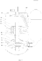
- the compressor includes a housing 30, a crankshaft 40, a cylinder 50, a piston 60, a main bearing 70, an auxiliary bearing 80, and an electric motor as described above.
- the housing 30 has a cylindrical shape, and defines a accommodating cavity 31 extending in the axial direction thereof.
- the crankshaft 40 is disposed in the accommodating cavity 31 and disposed along the axial direction of the housing 30. And the lower end of the crankshaft 40 passes through the cylinder 50, and a portion of the crankshaft 40 that extends into the cylinder 50 forms an eccentric portion, and a piston 60 is sleeved on the eccentric portion.
- the main bearing 70 and the auxiliary bearing 80 are respectively sleeved on the upper end and lower end of the crankshaft 40, and are fixed to the upper end and lower end of the cylinder 50 to seal the compression cavity 51 of the cylinder 50.
- the electric motor is disposed in the accommodating cavity 31 of the housing 30, and the rotor core 20 of the electric motor is connected to the upper end of the crankshaft 40.
- the wiring terminal connected to the control circuit of the electric motor is disposed at the inner wall of the accommodating cavity 31 of the compressor, the wiring terminal is inserted into the correspondingly plug connector of the electric motor.
- the motor lead 103a and the motor control circuit are electrically connected.
- the top of the compressor has an upper housing assembly 90, and one side of the upper housing assembly 90 facing the accommodating cavity 31 has a plurality of wiring terminals 901, the wiring terminals 901 are inserted into correspondingly plug connector of the electric motor.
- the motor lead 103a and the motor control circuit are electrically connected.
- the wiring terminal 901 includes a plurality of binding posts 902, which are plugged into the plug connector.
- the number of the binding posts depends on the number of coil ends of the plurality of coil groups of the electric motor. Since the number of windings of the electric motor generally does not exceed three, each coil group has one incoming line terminal and one outgoing line terminal. Therefore, at least six binding posts 902 are disposed on the compressor to enable the compressor to be fitted with more models of electric motors.
- the present disclosure is based on the fact that the total number of motor leads 103a in the two motor lead groups 103 is equal to twice the number of all coil groups. So that each motor lead 103a is connected to a line connecting terminal composed by one or more coil ends of one coil group, to controlling the circuit to conveniently switch the line connecting mode of the plurality of coil groups in the electric motor according to the working condition of the electric motor.
- the electrical connection mode of the plurality of motor leads 103a and the control circuit is not limited in the above embodiments.
- Other structures similar to the plug connector can be adopted to improve the connection efficiency of the motor leads 103a and the motor control circuit.
- the structure of plug connector can be slightly changed, and the present disclosure does not limit the structure of the plug connector.
- the compressor proposed in the present disclosure includes all the solutions of all the embodiments of the above-mentioned electric motor.
- the compressor at least has the same technical effects as the electric motor. And the details of which will not be explained here.
Landscapes
- Engineering & Computer Science (AREA)
- Power Engineering (AREA)
- Manufacturing & Machinery (AREA)
- Compressor (AREA)
- Windings For Motors And Generators (AREA)
- Connection Of Motors, Electrical Generators, Mechanical Devices, And The Like (AREA)
- Iron Core Of Rotating Electric Machines (AREA)
- Permanent Magnet Type Synchronous Machine (AREA)
Applications Claiming Priority (3)
| Application Number | Priority Date | Filing Date | Title |
|---|---|---|---|
| CN201710778317.1A CN107465279B (zh) | 2017-08-31 | 2017-08-31 | 电机及压缩机 |
| CN201721112311.2U CN207184181U (zh) | 2017-08-31 | 2017-08-31 | 电机及压缩机 |
| PCT/CN2018/088650 WO2019041915A1 (fr) | 2017-08-31 | 2018-05-28 | Moteur et compresseur |
Publications (3)
| Publication Number | Publication Date |
|---|---|
| EP3644476A1 true EP3644476A1 (fr) | 2020-04-29 |
| EP3644476A4 EP3644476A4 (fr) | 2020-07-15 |
| EP3644476B1 EP3644476B1 (fr) | 2025-03-05 |
Family
ID=65524886
Family Applications (1)
| Application Number | Title | Priority Date | Filing Date |
|---|---|---|---|
| EP18850551.5A Active EP3644476B1 (fr) | 2017-08-31 | 2018-05-28 | Moteur et compresseur |
Country Status (5)
| Country | Link |
|---|---|
| US (1) | US11545864B2 (fr) |
| EP (1) | EP3644476B1 (fr) |
| JP (1) | JP2020522226A (fr) |
| ES (1) | ES3025887T3 (fr) |
| WO (1) | WO2019041915A1 (fr) |
Families Citing this family (4)
| Publication number | Priority date | Publication date | Assignee | Title |
|---|---|---|---|---|
| JP2020522226A (ja) * | 2017-08-31 | 2020-07-27 | 広東美芝制冷設備有限公司 | 電気モーター及びコンプレッサー |
| JP7200240B2 (ja) * | 2017-12-27 | 2023-01-06 | 安徽美芝精密制造有限公司 | 永久磁石モーター及びコンプレッサー |
| US12191722B2 (en) * | 2019-05-31 | 2025-01-07 | MagniX USA, Inc. | High-torque electric motor assembly |
| CN114552824B (zh) | 2019-08-26 | 2023-11-10 | 安徽美芝精密制造有限公司 | 转子、电机、压缩机及制冷设备 |
Family Cites Families (12)
| Publication number | Priority date | Publication date | Assignee | Title |
|---|---|---|---|---|
| US6141864A (en) * | 1998-01-15 | 2000-11-07 | Trw Inc. | Motor stator winding tool |
| JP2001342954A (ja) * | 2000-05-31 | 2001-12-14 | Sanyo Electric Co Ltd | 電動圧縮機及びそれを用いた冷却装置 |
| JP2005124319A (ja) * | 2003-10-17 | 2005-05-12 | Mitsubishi Electric Corp | 回転電機の固定子及びその製造方法 |
| JP4619826B2 (ja) * | 2005-03-07 | 2011-01-26 | 三菱電機株式会社 | 電動機駆動装置、電動機駆動方法及び圧縮機 |
| CN103795304B (zh) * | 2012-11-01 | 2015-11-25 | 珠海格力节能环保制冷技术研究中心有限公司 | 三相同步电动机驱动控制系统及控制方法 |
| WO2015165012A1 (fr) * | 2014-04-28 | 2015-11-05 | Foster Assets Corporation | Moteur sans balai et son système |
| US9925889B2 (en) * | 2015-08-24 | 2018-03-27 | GM Global Technology Operations LLC | Electric machine for hybrid powertrain with dual voltage power system |
| CN108885039A (zh) * | 2016-01-29 | 2018-11-23 | Agc株式会社 | 制冷循环装置 |
| CN206211741U (zh) * | 2016-09-22 | 2017-05-31 | 中山大洋电机股份有限公司 | 一种可调速电机引线结构及可调速电机 |
| CN107017709A (zh) * | 2017-05-31 | 2017-08-04 | 广东美芝制冷设备有限公司 | 电机定子、永磁电机以及压缩机 |
| JP2020522226A (ja) * | 2017-08-31 | 2020-07-27 | 広東美芝制冷設備有限公司 | 電気モーター及びコンプレッサー |
| CN107465279B (zh) * | 2017-08-31 | 2023-04-25 | 广东美芝制冷设备有限公司 | 电机及压缩机 |
-
2018
- 2018-05-28 JP JP2019566575A patent/JP2020522226A/ja active Pending
- 2018-05-28 WO PCT/CN2018/088650 patent/WO2019041915A1/fr not_active Ceased
- 2018-05-28 EP EP18850551.5A patent/EP3644476B1/fr active Active
- 2018-05-28 ES ES18850551T patent/ES3025887T3/es active Active
-
2020
- 2020-01-14 US US16/741,878 patent/US11545864B2/en active Active
Also Published As
| Publication number | Publication date |
|---|---|
| US20200153304A1 (en) | 2020-05-14 |
| US11545864B2 (en) | 2023-01-03 |
| WO2019041915A1 (fr) | 2019-03-07 |
| EP3644476A4 (fr) | 2020-07-15 |
| ES3025887T3 (en) | 2025-06-10 |
| EP3644476B1 (fr) | 2025-03-05 |
| JP2020522226A (ja) | 2020-07-27 |
Similar Documents
| Publication | Publication Date | Title |
|---|---|---|
| US11545864B2 (en) | Electric motor and compressor | |
| CN107465279B (zh) | 电机及压缩机 | |
| JP6639569B2 (ja) | ステータアセンブリ | |
| US8525382B2 (en) | Electric motor having primary and auxiliary poles and brush gear | |
| US20210296948A1 (en) | Rotor, synchronous reluctance motor, and rotor forming method | |
| CN106787573A (zh) | 两极电刷换向直流电动马达 | |
| CN207098788U (zh) | 转子冲片、转子铁芯、转子、永磁电机及压缩机 | |
| CN107453501A (zh) | 转子冲片、转子铁芯、转子、永磁电机及压缩机 | |
| US6859993B2 (en) | Method of making single phase permanent split capacitor motor | |
| CN107425625A (zh) | 一种电机及压缩机 | |
| CN107370257B (zh) | 一种永磁电机及压缩机 | |
| CN207184181U (zh) | 电机及压缩机 | |
| CN207082917U (zh) | 一种电机及压缩机 | |
| CN210517930U (zh) | 单相四极串激电机的接线结构、单相四极串激电机 | |
| CN107370256B (zh) | 电机定子、三相永磁电机及压缩机 | |
| CN210518076U (zh) | 外转子马蹄铁型绕组永磁电机 | |
| CN203632516U (zh) | 无槽式无刷直流电机 | |
| CN202889152U (zh) | 一种单相交流永磁电动机 | |
| CN2534727Y (zh) | 抽油机用低速电动机 | |
| CN207082915U (zh) | 一种永磁电机及压缩机 | |
| CN222301493U (zh) | 电机 | |
| CN112583145A (zh) | 定子铁芯、定子、电机和风机 | |
| CN215733701U (zh) | 四极串励电机和食品加工机 | |
| CN212343439U (zh) | 一种4极6槽洗衣机电机 | |
| CN207200543U (zh) | 电机 |
Legal Events
| Date | Code | Title | Description |
|---|---|---|---|
| STAA | Information on the status of an ep patent application or granted ep patent |
Free format text: STATUS: THE INTERNATIONAL PUBLICATION HAS BEEN MADE |
|
| PUAI | Public reference made under article 153(3) epc to a published international application that has entered the european phase |
Free format text: ORIGINAL CODE: 0009012 |
|
| STAA | Information on the status of an ep patent application or granted ep patent |
Free format text: STATUS: REQUEST FOR EXAMINATION WAS MADE |
|
| 17P | Request for examination filed |
Effective date: 20200107 |
|
| AK | Designated contracting states |
Kind code of ref document: A1 Designated state(s): AL AT BE BG CH CY CZ DE DK EE ES FI FR GB GR HR HU IE IS IT LI LT LU LV MC MK MT NL NO PL PT RO RS SE SI SK SM TR |
|
| AX | Request for extension of the european patent |
Extension state: BA ME |
|
| A4 | Supplementary search report drawn up and despatched |
Effective date: 20200615 |
|
| RIC1 | Information provided on ipc code assigned before grant |
Ipc: H02K 3/28 20060101ALI20200608BHEP Ipc: H02K 1/16 20060101AFI20200608BHEP Ipc: H02K 3/52 20060101ALI20200608BHEP Ipc: H02K 15/00 20060101ALI20200608BHEP |
|
| STAA | Information on the status of an ep patent application or granted ep patent |
Free format text: STATUS: EXAMINATION IS IN PROGRESS |
|
| 17Q | First examination report despatched |
Effective date: 20201110 |
|
| DAV | Request for validation of the european patent (deleted) | ||
| DAX | Request for extension of the european patent (deleted) | ||
| GRAP | Despatch of communication of intention to grant a patent |
Free format text: ORIGINAL CODE: EPIDOSNIGR1 |
|
| STAA | Information on the status of an ep patent application or granted ep patent |
Free format text: STATUS: GRANT OF PATENT IS INTENDED |
|
| INTG | Intention to grant announced |
Effective date: 20241015 |
|
| GRAS | Grant fee paid |
Free format text: ORIGINAL CODE: EPIDOSNIGR3 |
|
| GRAA | (expected) grant |
Free format text: ORIGINAL CODE: 0009210 |
|
| STAA | Information on the status of an ep patent application or granted ep patent |
Free format text: STATUS: THE PATENT HAS BEEN GRANTED |
|
| AK | Designated contracting states |
Kind code of ref document: B1 Designated state(s): AL AT BE BG CH CY CZ DE DK EE ES FI FR GB GR HR HU IE IS IT LI LT LU LV MC MK MT NL NO PL PT RO RS SE SI SK SM TR |
|
| REG | Reference to a national code |
Ref country code: GB Ref legal event code: FG4D |
|
| REG | Reference to a national code |
Ref country code: CH Ref legal event code: EP |
|
| REG | Reference to a national code |
Ref country code: DE Ref legal event code: R096 Ref document number: 602018079903 Country of ref document: DE |
|
| REG | Reference to a national code |
Ref country code: IE Ref legal event code: FG4D |
|
| REG | Reference to a national code |
Ref country code: ES Ref legal event code: FG2A Ref document number: 3025887 Country of ref document: ES Kind code of ref document: T3 Effective date: 20250610 |
|
| PG25 | Lapsed in a contracting state [announced via postgrant information from national office to epo] |
Ref country code: RS Free format text: LAPSE BECAUSE OF FAILURE TO SUBMIT A TRANSLATION OF THE DESCRIPTION OR TO PAY THE FEE WITHIN THE PRESCRIBED TIME-LIMIT Effective date: 20250605 |
|
| PG25 | Lapsed in a contracting state [announced via postgrant information from national office to epo] |
Ref country code: FI Free format text: LAPSE BECAUSE OF FAILURE TO SUBMIT A TRANSLATION OF THE DESCRIPTION OR TO PAY THE FEE WITHIN THE PRESCRIBED TIME-LIMIT Effective date: 20250305 |
|
| REG | Reference to a national code |
Ref country code: NL Ref legal event code: MP Effective date: 20250305 |
|
| PGFP | Annual fee paid to national office [announced via postgrant information from national office to epo] |
Ref country code: ES Payment date: 20250602 Year of fee payment: 8 |
|
| REG | Reference to a national code |
Ref country code: LT Ref legal event code: MG9D |
|
| PG25 | Lapsed in a contracting state [announced via postgrant information from national office to epo] |
Ref country code: NO Free format text: LAPSE BECAUSE OF FAILURE TO SUBMIT A TRANSLATION OF THE DESCRIPTION OR TO PAY THE FEE WITHIN THE PRESCRIBED TIME-LIMIT Effective date: 20250605 |
|
| PGFP | Annual fee paid to national office [announced via postgrant information from national office to epo] |
Ref country code: IT Payment date: 20250519 Year of fee payment: 8 |
|
| PG25 | Lapsed in a contracting state [announced via postgrant information from national office to epo] |
Ref country code: HR Free format text: LAPSE BECAUSE OF FAILURE TO SUBMIT A TRANSLATION OF THE DESCRIPTION OR TO PAY THE FEE WITHIN THE PRESCRIBED TIME-LIMIT Effective date: 20250305 |
|
| PG25 | Lapsed in a contracting state [announced via postgrant information from national office to epo] |
Ref country code: LV Free format text: LAPSE BECAUSE OF FAILURE TO SUBMIT A TRANSLATION OF THE DESCRIPTION OR TO PAY THE FEE WITHIN THE PRESCRIBED TIME-LIMIT Effective date: 20250305 |
|
| PG25 | Lapsed in a contracting state [announced via postgrant information from national office to epo] |
Ref country code: BG Free format text: LAPSE BECAUSE OF FAILURE TO SUBMIT A TRANSLATION OF THE DESCRIPTION OR TO PAY THE FEE WITHIN THE PRESCRIBED TIME-LIMIT Effective date: 20250305 Ref country code: GR Free format text: LAPSE BECAUSE OF FAILURE TO SUBMIT A TRANSLATION OF THE DESCRIPTION OR TO PAY THE FEE WITHIN THE PRESCRIBED TIME-LIMIT Effective date: 20250606 |
|
| PGFP | Annual fee paid to national office [announced via postgrant information from national office to epo] |
Ref country code: TR Payment date: 20250425 Year of fee payment: 8 |
|
| REG | Reference to a national code |
Ref country code: AT Ref legal event code: MK05 Ref document number: 1773869 Country of ref document: AT Kind code of ref document: T Effective date: 20250305 |
|
| PG25 | Lapsed in a contracting state [announced via postgrant information from national office to epo] |
Ref country code: NL Free format text: LAPSE BECAUSE OF FAILURE TO SUBMIT A TRANSLATION OF THE DESCRIPTION OR TO PAY THE FEE WITHIN THE PRESCRIBED TIME-LIMIT Effective date: 20250305 |
|
| PG25 | Lapsed in a contracting state [announced via postgrant information from national office to epo] |
Ref country code: SE Free format text: LAPSE BECAUSE OF FAILURE TO SUBMIT A TRANSLATION OF THE DESCRIPTION OR TO PAY THE FEE WITHIN THE PRESCRIBED TIME-LIMIT Effective date: 20250305 |
|
| PG25 | Lapsed in a contracting state [announced via postgrant information from national office to epo] |
Ref country code: SM Free format text: LAPSE BECAUSE OF FAILURE TO SUBMIT A TRANSLATION OF THE DESCRIPTION OR TO PAY THE FEE WITHIN THE PRESCRIBED TIME-LIMIT Effective date: 20250305 |
|
| PG25 | Lapsed in a contracting state [announced via postgrant information from national office to epo] |
Ref country code: PT Free format text: LAPSE BECAUSE OF FAILURE TO SUBMIT A TRANSLATION OF THE DESCRIPTION OR TO PAY THE FEE WITHIN THE PRESCRIBED TIME-LIMIT Effective date: 20250707 |
|
| PG25 | Lapsed in a contracting state [announced via postgrant information from national office to epo] |
Ref country code: PL Free format text: LAPSE BECAUSE OF FAILURE TO SUBMIT A TRANSLATION OF THE DESCRIPTION OR TO PAY THE FEE WITHIN THE PRESCRIBED TIME-LIMIT Effective date: 20250305 |
|
| PG25 | Lapsed in a contracting state [announced via postgrant information from national office to epo] |
Ref country code: AT Free format text: LAPSE BECAUSE OF FAILURE TO SUBMIT A TRANSLATION OF THE DESCRIPTION OR TO PAY THE FEE WITHIN THE PRESCRIBED TIME-LIMIT Effective date: 20250305 |
|
| PG25 | Lapsed in a contracting state [announced via postgrant information from national office to epo] |
Ref country code: EE Free format text: LAPSE BECAUSE OF FAILURE TO SUBMIT A TRANSLATION OF THE DESCRIPTION OR TO PAY THE FEE WITHIN THE PRESCRIBED TIME-LIMIT Effective date: 20250305 Ref country code: CZ Free format text: LAPSE BECAUSE OF FAILURE TO SUBMIT A TRANSLATION OF THE DESCRIPTION OR TO PAY THE FEE WITHIN THE PRESCRIBED TIME-LIMIT Effective date: 20250305 |
|
| PG25 | Lapsed in a contracting state [announced via postgrant information from national office to epo] |
Ref country code: RO Free format text: LAPSE BECAUSE OF FAILURE TO SUBMIT A TRANSLATION OF THE DESCRIPTION OR TO PAY THE FEE WITHIN THE PRESCRIBED TIME-LIMIT Effective date: 20250305 |
|
| PG25 | Lapsed in a contracting state [announced via postgrant information from national office to epo] |
Ref country code: SK Free format text: LAPSE BECAUSE OF FAILURE TO SUBMIT A TRANSLATION OF THE DESCRIPTION OR TO PAY THE FEE WITHIN THE PRESCRIBED TIME-LIMIT Effective date: 20250305 |
|
| PG25 | Lapsed in a contracting state [announced via postgrant information from national office to epo] |
Ref country code: IS Free format text: LAPSE BECAUSE OF FAILURE TO SUBMIT A TRANSLATION OF THE DESCRIPTION OR TO PAY THE FEE WITHIN THE PRESCRIBED TIME-LIMIT Effective date: 20250705 |
|
| REG | Reference to a national code |
Ref country code: DE Ref legal event code: R119 Ref document number: 602018079903 Country of ref document: DE |
|
| REG | Reference to a national code |
Ref country code: CH Ref legal event code: H13 Free format text: ST27 STATUS EVENT CODE: U-0-0-H10-H13 (AS PROVIDED BY THE NATIONAL OFFICE) Effective date: 20251223 |
|
| PLBE | No opposition filed within time limit |
Free format text: ORIGINAL CODE: 0009261 |
|
| STAA | Information on the status of an ep patent application or granted ep patent |
Free format text: STATUS: NO OPPOSITION FILED WITHIN TIME LIMIT |
|
| PG25 | Lapsed in a contracting state [announced via postgrant information from national office to epo] |
Ref country code: DK Free format text: LAPSE BECAUSE OF FAILURE TO SUBMIT A TRANSLATION OF THE DESCRIPTION OR TO PAY THE FEE WITHIN THE PRESCRIBED TIME-LIMIT Effective date: 20250305 |
|
| REG | Reference to a national code |
Ref country code: CH Ref legal event code: L10 Free format text: ST27 STATUS EVENT CODE: U-0-0-L10-L00 (AS PROVIDED BY THE NATIONAL OFFICE) Effective date: 20260114 |
|
| PG25 | Lapsed in a contracting state [announced via postgrant information from national office to epo] |
Ref country code: LU Free format text: LAPSE BECAUSE OF NON-PAYMENT OF DUE FEES Effective date: 20250528 |
|
| PG25 | Lapsed in a contracting state [announced via postgrant information from national office to epo] |
Ref country code: CH Free format text: LAPSE BECAUSE OF NON-PAYMENT OF DUE FEES Effective date: 20250531 |
|
| REG | Reference to a national code |
Ref country code: BE Ref legal event code: MM Effective date: 20250531 |
|
| PG25 | Lapsed in a contracting state [announced via postgrant information from national office to epo] |
Ref country code: MC Free format text: LAPSE BECAUSE OF FAILURE TO SUBMIT A TRANSLATION OF THE DESCRIPTION OR TO PAY THE FEE WITHIN THE PRESCRIBED TIME-LIMIT Effective date: 20250305 |
|
| 26N | No opposition filed |
Effective date: 20251208 |
|
| GBPC | Gb: european patent ceased through non-payment of renewal fee |
Effective date: 20250605 |
|
| PG25 | Lapsed in a contracting state [announced via postgrant information from national office to epo] |
Ref country code: GB Free format text: LAPSE BECAUSE OF NON-PAYMENT OF DUE FEES Effective date: 20250605 |
|
| PG25 | Lapsed in a contracting state [announced via postgrant information from national office to epo] |
Ref country code: IE Free format text: LAPSE BECAUSE OF NON-PAYMENT OF DUE FEES Effective date: 20250528 Ref country code: DE Free format text: LAPSE BECAUSE OF NON-PAYMENT OF DUE FEES Effective date: 20251202 |
|
| PG25 | Lapsed in a contracting state [announced via postgrant information from national office to epo] |
Ref country code: BE Free format text: LAPSE BECAUSE OF NON-PAYMENT OF DUE FEES Effective date: 20250531 |
|
| PG25 | Lapsed in a contracting state [announced via postgrant information from national office to epo] |
Ref country code: FR Free format text: LAPSE BECAUSE OF NON-PAYMENT OF DUE FEES Effective date: 20250531 |