EP3644612A1 - Procédé et dispositif de codage et de décodage d'images - Google Patents
Procédé et dispositif de codage et de décodage d'images Download PDFInfo
- Publication number
- EP3644612A1 EP3644612A1 EP18306384.1A EP18306384A EP3644612A1 EP 3644612 A1 EP3644612 A1 EP 3644612A1 EP 18306384 A EP18306384 A EP 18306384A EP 3644612 A1 EP3644612 A1 EP 3644612A1
- Authority
- EP
- European Patent Office
- Prior art keywords
- sample
- prediction
- padded
- reference sample
- block
- Prior art date
- Legal status (The legal status is an assumption and is not a legal conclusion. Google has not performed a legal analysis and makes no representation as to the accuracy of the status listed.)
- Withdrawn
Links
- 238000000034 method Methods 0.000 title claims abstract description 110
- 239000013074 reference sample Substances 0.000 claims abstract description 148
- 239000000523 sample Substances 0.000 claims abstract description 104
- 230000007423 decrease Effects 0.000 claims abstract description 19
- 230000008569 process Effects 0.000 description 33
- 230000015654 memory Effects 0.000 description 26
- 230000006870 function Effects 0.000 description 21
- 238000012545 processing Methods 0.000 description 19
- 238000004891 communication Methods 0.000 description 18
- 238000010586 diagram Methods 0.000 description 9
- 238000000638 solvent extraction Methods 0.000 description 8
- 238000013459 approach Methods 0.000 description 7
- 238000005457 optimization Methods 0.000 description 7
- 230000011664 signaling Effects 0.000 description 7
- 230000006835 compression Effects 0.000 description 6
- 238000007906 compression Methods 0.000 description 6
- 238000006073 displacement reaction Methods 0.000 description 6
- 238000013139 quantization Methods 0.000 description 6
- 230000001419 dependent effect Effects 0.000 description 5
- 208000037170 Delayed Emergence from Anesthesia Diseases 0.000 description 4
- 238000001914 filtration Methods 0.000 description 4
- 230000002093 peripheral effect Effects 0.000 description 4
- 230000005540 biological transmission Effects 0.000 description 3
- 230000008859 change Effects 0.000 description 3
- 230000000694 effects Effects 0.000 description 3
- 238000012360 testing method Methods 0.000 description 3
- 230000008901 benefit Effects 0.000 description 2
- 230000001364 causal effect Effects 0.000 description 2
- 238000006243 chemical reaction Methods 0.000 description 2
- 238000012937 correction Methods 0.000 description 2
- 238000011156 evaluation Methods 0.000 description 2
- 230000003287 optical effect Effects 0.000 description 2
- 238000005192 partition Methods 0.000 description 2
- 230000002123 temporal effect Effects 0.000 description 2
- 230000009466 transformation Effects 0.000 description 2
- 230000007704 transition Effects 0.000 description 2
- 239000013598 vector Substances 0.000 description 2
- 230000003936 working memory Effects 0.000 description 2
- 238000012935 Averaging Methods 0.000 description 1
- 241000023320 Luma <angiosperm> Species 0.000 description 1
- 230000003044 adaptive effect Effects 0.000 description 1
- 230000001413 cellular effect Effects 0.000 description 1
- 239000002131 composite material Substances 0.000 description 1
- 238000004590 computer program Methods 0.000 description 1
- 238000013500 data storage Methods 0.000 description 1
- 230000003247 decreasing effect Effects 0.000 description 1
- 238000005516 engineering process Methods 0.000 description 1
- 230000014509 gene expression Effects 0.000 description 1
- 238000009499 grossing Methods 0.000 description 1
- 238000013507 mapping Methods 0.000 description 1
- OSWPMRLSEDHDFF-UHFFFAOYSA-N methyl salicylate Chemical compound COC(=O)C1=CC=CC=C1O OSWPMRLSEDHDFF-UHFFFAOYSA-N 0.000 description 1
- 239000000203 mixture Substances 0.000 description 1
- 229920001690 polydopamine Polymers 0.000 description 1
- 238000012805 post-processing Methods 0.000 description 1
- 238000007781 pre-processing Methods 0.000 description 1
- 230000003252 repetitive effect Effects 0.000 description 1
- 239000012723 sample buffer Substances 0.000 description 1
- 239000004065 semiconductor Substances 0.000 description 1
- 238000001228 spectrum Methods 0.000 description 1
- 230000003068 static effect Effects 0.000 description 1
- 238000006467 substitution reaction Methods 0.000 description 1
Images



Classifications
-
- H—ELECTRICITY
- H04—ELECTRIC COMMUNICATION TECHNIQUE
- H04N—PICTORIAL COMMUNICATION, e.g. TELEVISION
- H04N19/00—Methods or arrangements for coding, decoding, compressing or decompressing digital video signals
- H04N19/10—Methods or arrangements for coding, decoding, compressing or decompressing digital video signals using adaptive coding
- H04N19/134—Methods or arrangements for coding, decoding, compressing or decompressing digital video signals using adaptive coding characterised by the element, parameter or criterion affecting or controlling the adaptive coding
- H04N19/167—Position within a video image, e.g. region of interest [ROI]
-
- H—ELECTRICITY
- H04—ELECTRIC COMMUNICATION TECHNIQUE
- H04N—PICTORIAL COMMUNICATION, e.g. TELEVISION
- H04N19/00—Methods or arrangements for coding, decoding, compressing or decompressing digital video signals
- H04N19/10—Methods or arrangements for coding, decoding, compressing or decompressing digital video signals using adaptive coding
- H04N19/102—Methods or arrangements for coding, decoding, compressing or decompressing digital video signals using adaptive coding characterised by the element, parameter or selection affected or controlled by the adaptive coding
- H04N19/103—Selection of coding mode or of prediction mode
- H04N19/105—Selection of the reference unit for prediction within a chosen coding or prediction mode, e.g. adaptive choice of position and number of pixels used for prediction
-
- H—ELECTRICITY
- H04—ELECTRIC COMMUNICATION TECHNIQUE
- H04N—PICTORIAL COMMUNICATION, e.g. TELEVISION
- H04N19/00—Methods or arrangements for coding, decoding, compressing or decompressing digital video signals
- H04N19/10—Methods or arrangements for coding, decoding, compressing or decompressing digital video signals using adaptive coding
- H04N19/169—Methods or arrangements for coding, decoding, compressing or decompressing digital video signals using adaptive coding characterised by the coding unit, i.e. the structural portion or semantic portion of the video signal being the object or the subject of the adaptive coding
- H04N19/17—Methods or arrangements for coding, decoding, compressing or decompressing digital video signals using adaptive coding characterised by the coding unit, i.e. the structural portion or semantic portion of the video signal being the object or the subject of the adaptive coding the unit being an image region, e.g. an object
- H04N19/176—Methods or arrangements for coding, decoding, compressing or decompressing digital video signals using adaptive coding characterised by the coding unit, i.e. the structural portion or semantic portion of the video signal being the object or the subject of the adaptive coding the unit being an image region, e.g. an object the region being a block, e.g. a macroblock
-
- H—ELECTRICITY
- H04—ELECTRIC COMMUNICATION TECHNIQUE
- H04N—PICTORIAL COMMUNICATION, e.g. TELEVISION
- H04N19/00—Methods or arrangements for coding, decoding, compressing or decompressing digital video signals
- H04N19/50—Methods or arrangements for coding, decoding, compressing or decompressing digital video signals using predictive coding
- H04N19/593—Methods or arrangements for coding, decoding, compressing or decompressing digital video signals using predictive coding involving spatial prediction techniques
-
- H—ELECTRICITY
- H04—ELECTRIC COMMUNICATION TECHNIQUE
- H04N—PICTORIAL COMMUNICATION, e.g. TELEVISION
- H04N19/00—Methods or arrangements for coding, decoding, compressing or decompressing digital video signals
- H04N19/10—Methods or arrangements for coding, decoding, compressing or decompressing digital video signals using adaptive coding
- H04N19/102—Methods or arrangements for coding, decoding, compressing or decompressing digital video signals using adaptive coding characterised by the element, parameter or selection affected or controlled by the adaptive coding
- H04N19/103—Selection of coding mode or of prediction mode
- H04N19/11—Selection of coding mode or of prediction mode among a plurality of spatial predictive coding modes
Definitions
- At least one of the present embodiments generally relate to a method and a device for picture encoding and decoding, and more particularly, to a method and a device for picture encoding and decoding using intra prediction.
- image and video coding schemes usually employ prediction and transform to leverage spatial and temporal redundancy in the video content.
- intra or inter prediction is used to exploit the intra or inter frame correlation, then the differences between the original image block and the predicted image block, often denoted as prediction errors, prediction residuals or predictor, are transformed, quantized and entropy coded.
- the original image block is usually partitioned/split into sub-blocks possibly using quad-tree partitioning.
- the compressed data is decoded by inverse processes corresponding to the prediction, transform, quantization and entropy coding.
- a decoding method that comprises:
- an encoding method that comprises:
- an apparatus comprising one or more processors configured to perform:
- an apparatus comprising one or more processors configured to perform: encoding the current block using the prediction block; wherein at least one sample of the prediction block is obtained by a linear combination of reference samples, one reference sample being padded, wherein a weight associated with the padded reference sample decreases as a function of a distance between the padded reference sample and a last available reference sample.
- One or more of the present embodiments also provide a computer readable storage medium having stored thereon instructions for encoding or decoding video data according to at least part of any of the methods described above.
- One or more embodiments also provide a computer readable storage medium having stored thereon a bitstream generated according to the encoding methods described above.
- One or more embodiments also provide a method and apparatus for transmitting or receiving the bitstream generated according to the encoding methods described above.
- One or more embodiments also provide a computer program product including instructions for performing at least part of any of the methods described above.
- a picture is partitioned into CTUs of square shape with a configurable size typically 64x64. The size may be 128x128, or 256x256 in other video coding standards.
- a CTU is the root of a quad-tree partitioning into 4 square Coding Units (CU) of equal size, i.e. half of the parent block size in width and in height.
- CU square Coding Unit
- a quad-tree is a tree in which a parent node can be split into four child nodes, each of which may become parent node for another split into four child nodes.
- a coding Block is partitioned into one or more Prediction Blocks (PB) and forms the root of a quadtree partitioning into Transform Blocks (TBs).
- PB Prediction Blocks
- TBs Transform Blocks
- a Coding Unit includes the Prediction Units (PUs) and the tree-structured set of Transform Units (TUs), a PU includes the prediction information for all color components, and a TU includes residual coding syntax structure for each color component.
- the size of a CB, PB and TB of the luma component applies to the corresponding CU, PU and TU.
- a CTU is the root of a coding tree partitioning into Coding Units (CU).
- a coding tree is a tree in which a parent node (usually corresponding to a block) can be split into child nodes (e.g. into 2, 3 or 4 child nodes), each of which may become parent node for another split into child nodes.
- new split modes binary tree symmetric split modes, binary tree asymmetric split modes and triple tree split modes
- Figure 1 depicts examples of such split modes.
- the two split modes on the left are classical binary split mode that split a block into two identical sub-blocks either vertically (SPLIT_BT_VER) or horizontally (SPLIT_BT_HOR).
- the two split modes on the right are examples of triple tree split modes.
- the SPLIT_TT_VER mode splits a block into three sub-blocks vertically of respective widths N/4, N/2 and N/4.
- the SPLIT_TT_HOR mode splits a block into three sub-blocks horizontally of respective heights N/4, N/2 and N/4.
- the coding tree has a unique root node, e.g. a CTU.
- a leaf of the coding tree is a terminating node of the tree.
- Each node of the coding tree represents a block that may be further split into smaller blocks also named sub-blocks or more generally sub-blocks.
- CUs corresponding to the leaves of the coding tree are encoded.
- the partitioning of a CTU into CUs and the coding parameters used for encoding each CU (corresponding to a leaf of the coding tree) may be determined on the encoder side through a rate distortion optimization procedure.
- Figure 2 depicts a CTU split into CUs according to various split modes. More precisely, it represents a coding tree of a CU with nested Quad Tree (QT), Binary Tree (BT) and Triple Tree (TT) structures.
- QT Quad Tree
- BT Binary Tree
- TT Triple Tree
- block or “picture block” can be used to refer to any one of a CTU, a CU, a PU, a TU, a CB, a PB and a TB.
- block or “picture block” can be used to refer to a macroblock, a partition and a sub-block as specified in H.264/AVC or in other video coding standards, and more generally to refer to an array of samples of numerous sizes.
- the terms “reconstructed” and “decoded” may be used interchangeably, the terms “pixel” and “sample” may be used interchangeably, the terms “image,” “picture” and “frame” may be used interchangeably.
- the term “reconstructed” is used at the encoder side while “decoded” is used at the decoder side.
- Intra prediction in video compression refers to the spatial prediction of a block of pixels using the information from the causal neighbor blocks, that is, the neighboring blocks in the same frame which have already been decoded. This is a powerful coding tool since it allows for high compression efficiency in INTRA frames, as well as in INTER frames whenever there is no better temporal prediction. Therefore, intra prediction has been included as a core coding tool in all video compression standards including H.264/AVC, HEVC, etc.
- Intra prediction exploits the spatial correlation among the pixels which may belong to the same object, background or region, etc.
- the intra prediction in video coding standards such as H.264/AVC, H.265/HEVC, etc.
- the intra prediction has been designed to capture directionalities of object orientations and the slow changing intensity of regions or textures.
- the intra prediction includes 35 prediction modes which include one DC, one PLANAR, and 33 angular prediction modes.
- the angular modes are designed to model the directional structures of objects whereas the DC and the planar modes provide predictions for regions with slow and gradual intensity change, and also for regions with varying textures.
- VTM Versatile Video Coding Test Model
- PDPC Position Dependent intra Prediction Combination
- encoding of a frame of video sequence is based on a quad-tree (QT) block structure.
- a frame is divided into square coding tree units (CTUs) which all undergo quad-tree based splitting to multiple coding units (CUs) based on rate-distortion criteria.
- Each CU contains at least one prediction unit (PU), which are the basis blocks for prediction tools.
- PU prediction unit
- Intra prediction a PU is spatially predicted from the causal neighbor PUs, i.e., the PUs on the top and the left.
- HEVC uses simple spatial models called prediction modes.
- the encoder constructs different predictions for the target block and chooses the one that leads to the best RD performance.
- one is a planar mode (indexed as mode 0)
- one is a DC mode (indexed as mode 1)
- the remaining 33 is angular modes.
- the angular modes aim to model the directional structures of objects in a frame. Therefore, the decoded pixel values in the top and left CUs are simply repeated along the defined directions to fill up the prediction block. Since this process can lead to discontinuities along the top and left reference boundaries for certain modes, those prediction modes include a subsequent post-filtering to smooth the pixel values along those boundaries.
- the intra prediction process in HEVC comprises three steps: (1) reference sample generation (2) intra sample prediction and (3) post-processing of predicted samples.
- the reference sample generation process is illustrated in Figure 3 .
- a row of 2N decoded samples on the top is formed from the previously reconstructed top and top right pixels to the current PU.
- a column of 2N samples on the left is formed from the reconstructed left and below left pixels.
- the corner pixel at the top-left position is also used to fill up the gap between the top row and the left column references. If some of the samples on top or left are not available, e.g. because of the corresponding CUs not being in the same slice, or the current CU being at a frame boundary, then a method called reference sample substitution is performed where the missing samples are copied from the available samples in a clockwise direction. Then, depending on the current CU size and the prediction mode, the reference samples are filtered using a specified filter.
- the next step i.e., the intra sample prediction, consists of predicting the pixels of the target CU based on the reference samples.
- HEVC supports a range of prediction models. Planar and DC prediction modes are used to predict smooth and gradually changing regions, whereas angular prediction modes are used to capture different directional structures.
- HEVC supports 33 directional prediction modes which are indexed from 2 to 34. These prediction modes correspond to different prediction directions as illustrated in Figure 4 .
- the defined angular directions result in a sample accuracy of 1/32. That is, between any two adjacent reference samples, there are 32 possible directions.
- the defined directions can be distinguished as either vertical or horizontal.
- the predictions in horizontal directions use either only left reference samples or some left and some top reference samples.
- the predictions in vertical directions use either only top reference samples or some top and some left reference samples.
- the directions which use only left reference samples or only the top reference samples are defined to be positive directions. Thus, we have horizontal positive directions from H0 to H+32 that use only the left reference samples. Similarly, we have vertical positive directions from V0 to V+32 that use only the top reference samples.
- H-2 to H-26 and V-2 to V-32) are defined to be negative directions and they use reference samples both on the left and on the top.
- the table below shows the relationship between the prediction mode and the angle parameter A as specified by HEVC: Table 1 Mapping of mode index to angle parameter A Horizontal directions Mode index 2 3 4 5 6 7 8 9 10 11 12 13 14 15 16 17 A 32 26 21 17 13 9 5 2 0 -2 -5 -9 -13 -17 -21 -26 Vertical directions Mode index 18 19 20 21 22 23 24 25 26 27 28 29 30 31 32 33 34 A -32 -26 -21 -17 -9 -5 -2 0 2 5 9 13 17 21 26 32
- the reference array For the modes with negative angle parameter A (modes 11 to 25), the reference array needs pixels from both the top and left reference. In this case, the reference array will extend to the negative indices beyond 0. Sample values on the reference array with positive indices are obtained as above depending on vertical or horizontal prediction. Those on the reference array with negative indices are obtained by projecting the left (for vertical predictions) or top reference pixels (for horizontal predictions) on the reference array along the prediction direction.
- the prediction sample value Pred[x] [y] at any pixel position ( x,y ) inside the target CU is obtained by first projecting the pixel position ( x,y ) to the reference array along the selected direction to obtain the reference array position indices i (integer index) and f (fractional index).
- Pred x y 32 ⁇ f ⁇ topRef x + i + 1 + f ⁇ topRef x + i + 2 + 16 ) > > 5 , 0 ⁇ x , y ⁇ N , for vertical predictions
- Pred x y 32 ⁇ f ⁇ leftRef y + i + 1 + f ⁇ leftRef y + i + 2 + 16 ) > > 5 , 0 ⁇ x , y ⁇ N , for horizontal predictions where i and f denote the integer part and the fractional part of the projected displacement from the pixel location ( x,y ).
- the prediction is equal to the reference array sample in the direction of prediction.
- the vertical predictions are independent of the y-coordinate and the horizontal predictions are independent of the x-coordinate. This means that, for vertical predictions, the prediction values are repeated along the direction of prediction from the reference array on the top. Similarly, for horizontal predictions, the prediction values are repeated along the direction of prediction from the reference array on the left. Therefore, if two or more pixel's coordinates have the same projection point on the reference array, they have identical prediction values.
- the number of prediction modes has been increased to 67, which includes one planar mode, one DC mode, and 65 angular modes.
- the higher number of angular modes correspond to 65 prediction directions where the prediction directions correspond to the 33 directions in HEVC plus additional 32 directions that correspond to the middle of any two adjacent directions.
- the prediction direction has twice the angle resolution of HEVC.
- the higher number of prediction modes makes it possible to exploit the possibility of such angular structures with proposed higher block sizes.
- the modes are numbered from 2 to 66 in the increasing order and in the same fashion as done in HEVC from 2 to 34.
- VTM can also have rectangular CUs because of Multi-type tree (MTT) splitting modes as illustrated by Figures 1 and 2 .
- MTT Multi-type tree
- the prediction process basically remains the same as in HEVC.
- Pred x y 32 ⁇ f ⁇ topRef x + i + 1 + f ⁇ topRef x + i + 2 + 16 > > 5 , 0 ⁇ x ⁇ W , 0 ⁇ y ⁇ H , for vertical predictions
- Pred x y 32 ⁇ f ⁇ leftRef y + i + 1 + f ⁇ leftRef y + i + 2 + 16 > > 5 , 0 ⁇ x ⁇ W , 0 ⁇ y ⁇ H , for horizontal predictions ,
- the interpolation has a sample accuracy of (1/32).
- PDPC position dependent intra prediction combination
- PDPC is an intra prediction method which invokes a combination of the un-filtered reference samples and HEVC style intra prediction (with possibly filtered reference samples).
- PDPC is applied to the following intra modes without signaling: planar, DC, horizontal, vertical, bottom-left angular mode and its eight adjacent angular modes, and top-right angular mode and its eight adjacent angular modes (called "adjacent modes").
- Figure 5 illustrates the definition of reference samples R(x,-1), R(-1,y) and R(-1,-1) used by PDPC when applied over various prediction modes.
- the prediction sample pred (x', y') is located at (x', y') within the prediction block.
- Diagonal top-right 16 >> (( y' ⁇ 1) >> shift ) 16 >> (( x' ⁇ 1) >> shift ) 0
- Diagonal bottom-left 16 >> (( y' ⁇ 1) >> shift ) 16 >> (( x ' ⁇ 1) >> shift ) 0
- Adjacent diagonal top-right 32 >> (( y' ⁇ 1) >> shift ) 0 0
- Intra prediction process relies on decoded reference pixels. Some of the reference pixels may be unavailable. It happens mostly on the left and top of image (or slice, or tile), and also inside a (slice, tile, or CTU) depending on the coding order of the blocks (CUs).
- Figure 6 depicts a block to be intra predicted for which some of the reference pixels are unavailable. In such a case, padding can be used to create the full reference sample buffer. On figure 6 , the unavailable samples are padded from the last available sample, e.g. P[N-1][-1].
- Figure 7 depicts a block to be predicted according to a directional intra prediction for which samples are unavailable. In this case, the unavailable samples can be padded. When reference samples are not available (i.e. not decoded yet, or at frontier of image/CTU), the padded reference can be used. The last available pixel on the row or column is extended to the end of the reference sample buffer. Using padded reference samples is inaccurate and may lead to compression performance loss.
- At least one embodiment proposes to improve the prediction efficiency in intra prediction by adapting the prediction when reference samples are not available. At least one embodiment proposes to manage cases where reference samples are missing for the intra prediction, i.e. when samples are padded to fill the ref sample buffer.
- the last top (resp. last left) available reference sample index IT (resp. 1L) is stored in a memory.
- the index starts at 0 from the top-left pixel (P-1, -1).
- Figure 8A illustrates the process of marking the last available sample. The marking of the last available sample is used in the various embodiments disclosed below. The last available sample is the last non-padded sample.
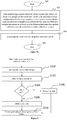
- Figure 8B depicts a flowchart of a decoding method according to one embodiment.
- the method starts at S10.
- a current block is intra predicted to obtain a prediction block.
- At least one sample of the prediction block is obtained by a linear combination of reference samples, wherein one reference sample is padded.
- a weight associated with the padded reference sample decreases as a function of a distance, namely a spatial distance, between the padded reference sample and a last available reference sample.
- the current block is decoded at S14 using the prediction block.
- the method ends at S16.
- Figure 8C depicts a flowchart of an encoding method according to one embodiment.
- the method starts at S20.
- a current block is intra predicted to obtain a prediction block.
- At least one sample of the prediction block is obtained by a linear combination of reference samples, wherein one reference sample is padded.
- a weight associated with the padded reference sample decreases as a function of a distance, namely a spatial distance, between the padded reference sample and a last available reference sample.
- the current block is encoded at S24 using the prediction block.
- the method ends at S26.
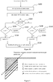
- Figure 9 depicts a flowchart of a prediction method according to one embodiment.
- the last available reference sample is marked as illustrated by Figure 8A .
- the values A, nbP and nbPTh are determined.
- A is the angle parameter and is determined from the intra mode.
- nbP is the number of predicted pixels (nbP) obtained from padded pixels and nbPTh is a value.
- nbP W ⁇ lT + H ⁇ A > > 5
- W, H are the width and height of the block
- A is the angle parameter as defined in Table 1.
- the corresponding direction for directional prediction is disabled (S106). Said otherwise, the corresponding intra mode is discarded (S106). In the case where nbP ⁇ nbPTh, the corresponding mode is considered as available (S108) to encode/decode the target block.
- the block is encoded (resp. decoded) using the available intra modes. Encoding comprises determining residual block by subtracting prediction block from original block, transform and quantize residual block and entropy encode the quantized transform coefficients and also an indication of an intra prediction mode.
- Decoding comprises entropy decode transform coefficients and also an indication of an intra prediction mode, dequantize and inverse transform the transform coefficients to obtain a residual block. Reconstructing a block by adding the residual block to the prediction block.
- the advantage is to reduce the possible intra modes and thus reduce signaling of intra direction.
- the processing time at encoder can also be reduced since less intra modes are tested, e.g. by rate distortion optimization.
- This method can be an encoder-only method, but better performance can be achieved if transmission of the final mode is modified accordingly, so that fewer bits are needed when some modes are unavailable.
- the transmission of the modes can be done as follows:
- the amount of predicted pixels from padded reference can also be expressed as an area aP.
- the value nbPTh is replaced by aPTh.
- the value aPTh can be set to WxH/4, or to WxH/2.
- aP is compared to aPTh.
- equations are applicable for positive vertical directions.
- the block is transposed (thus x and y coordinates, W and H sizes, 1T and 1L are swapped), and the equations can also be applied.
- Figure 10 depicts a flowchart of a prediction method that uses PDPC according to one embodiment.
- the last available reference sample is marked as illustrated by Figure 8A .
- the indices x and y of the PDPC reference sample are determined.
- the intra mode is a horizontal mode (S204)
- the method continues at S206 otherwise it continues at S208.
- the PDPC is applied (S210). Otherwise (S212) PDPC is skipped or deactivated.
- PDPC is a block boundary filter. If the reference pixel is a padded one, the advantage of PDPC is significantly reduced. In this case, the corresponding weight is set to 0, which has the same effect as disabling pixel-wise the PDPC filter.
- the PDPC is applied (S214). Otherwise (S216) PDPC is skipped.
- the block is encoded (resp. decoded) using the prediction after PDPC is applied.
- the block is encoded (resp. decoded) using the prediction without PDPC.
- the block is encoded (resp. decoded) using the prediction without PDPC.
- This embodiment makes it possible to reduce computations for pixels without PDPC reference pixel.
- This embodiment may be used in combination with the embodiment of Figure 9 or independently.
- the effect of PDPC is increased when the conventional prediction comes from an unavailable (padded) reference sample. If for the current pixel, the reference sample index is above the last available index, then, modify the PDPC weight such that more importance is given to pixel from the left (resp. top) prediction for vertical (resp. horizontal) direction. For example, the PDPC weight is modified so that it decreases slower. In that case the effect of PDPC will be on a larger area. For example, the weights are modified as follows:
- This embodiment may be used in combination with the embodiment of Figure 9 or 10 or independently.
- Figure 11 illustrates a prediction method according to one embodiment.
- samples are not available for conventional prediction (e.g. top-right reference samples are not available on Figure 11 )
- prediction from opposite direction is used instead.
- the intra prediction process uses the inverse angle to use the prediction from the other side of the block. If none of the reference samples are available, the conventional padded reference sample is used.
- angle parameter A e.g. A being specified by HEVC
- invAngle Round 256 ⁇ 32 A
- This embodiment may be used in combination with any of the previous embodiments and their variants or independently.
- both predictions are averaged to obtain the predicted pixel if both reference pixels are padded ones (unavailable).
- the transition between conventional and inverse angle is smoothed to avoid creating an undesired edge in the prediction.
- the transition is indicated by a dotted line. Therefore, in an embodiment, both predictions (conventional and inverse angle) are used with varying weights depending on the distance of the reference pixel from the last available reference pixel.
- pred x y wI ⁇ invPred x y + 64 ⁇ wI ⁇ pred x y + 32 > > 6
- invPred(x, y) is the inverse prediction
- pred(x,y) is the conventional prediction that is being modified
- wI is the weight associated with the inverse prediction at current pixel (x,y).
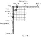
- Figure 12 illustrates a prediction method according to one embodiment.
- a linear combination P ⁇ of inverse prediction P2 and conventional prediction P1 is used with a weight that depends on the distance between predicted sample position and reference sample position.
- the top reference sample is a padded one
- two reference samples are used for computing the prediction for a target pixel.
- the second reference sample is located at the intersection of the prediction direction with the second reference array.
- the two reference samples are then weighted with a weight that depends on the distance, namely a spatial distance, between predicted pixel position and reference sample position.
- the first reference sample (from HEVC style intra prediction) is at displacement ⁇ from x-coordinate of the target pixel at (x,y).
- the second reference sample (inverse prediction as defined in embodiment of Figure 11 ) is at displacement ⁇ i from the y-coordinate of the target pixel at (x,y).
- P 1 and P 2 are the first and the second reference sample values for a target pixel, ⁇ P is the update, and P ⁇ is the final prediction value. For positive horizontal prediction directions, the computations are similar, when transposing the block.
- At least one embodiment of the prediction methods will model object orientations with intensity variation better than the normal repetitive prediction leading to better RD performance.
- FIG. 13 , 14 and 15 provide some embodiments, but other embodiments are contemplated and the discussion of Figures 13 , 14 and 15 does not limit the breadth of the implementations.
- At least one of the aspects generally relates to video encoding and decoding, and at least one other aspect generally relates to transmitting a bitstream generated or encoded.
- These and other aspects can be implemented as a method, an apparatus, a computer readable storage medium having stored thereon instructions for encoding or decoding video data according to any of the methods described, and/or a computer readable storage medium having stored thereon a bitstream generated according to any of the methods described.
- modules for example, the intra prediction, entropy coding, and/or decoding modules (160, 260, 145, 230), of a video encoder 100 and decoder 200 as shown in Figures 13 and 14 .
- the present aspects are not limited to VVC or HEVC, and can be applied, for example, to other standards and recommendations, whether pre-existing or future-developed, and extensions of any such standards and recommendations (including VVC and HEVC). Unless indicated otherwise, or technically precluded, the aspects described in this application can be used individually or in combination.
- nbPTh numeric values
- the specific values are for example purposes and the aspects described are not limited to these specific values.
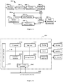
- Figure 13 illustrates an encoder 100. Variations of this encoder 100 are contemplated, but the encoder 100 is described below for purposes of clarity without describing all expected variations.
- the video sequence may go through pre-encoding processing (101), for example, applying a color transform to the input color picture (e.g., conversion from RGB 4:4:4 to YCbCr 4:2:0), or performing a remapping of the input picture components in order to get a signal distribution more resilient to compression (for instance using a histogram equalization of one of the color components).
- Metadata can be associated with the pre-processing, and attached to the bitstream.
- a picture is encoded by the encoder elements as described below.
- the picture to be encoded is partitioned (102) and processed in units of, for example, CUs.
- Each unit is encoded using, for example, either an intra or inter mode.
- intra prediction 160
- inter mode motion estimation (175) and compensation (170) are performed.
- the encoder decides (105) which one of the intra mode or inter mode to use for encoding the unit, and indicates the intra/inter decision by, for example, a prediction mode flag.
- Prediction residuals are calculated, for example, by subtracting (110) the predicted block from the original image block.
- the prediction residuals are then transformed (125) and quantized (130).
- the quantized transform coefficients, as well as motion vectors and other syntax elements, are entropy coded (145) to output a bitstream.
- the encoder can skip the transform and apply quantization directly to the non-transformed residual signal.
- the encoder can bypass both transform and quantization, i.e., the residual is coded directly without the application of the transform or quantization processes.
- the encoder decodes an encoded block to provide a reference for further predictions.
- the quantized transform coefficients are de-quantized (140) and inverse transformed (150) to decode prediction residuals.
- In-loop filters (165) are applied to the reconstructed picture to perform, for example, deblocking/SAO (Sample Adaptive Offset) filtering to reduce encoding artifacts.
- the filtered image is stored at a reference picture buffer (180).
- Figure 14 illustrates a block diagram of a video decoder 200.
- a bitstream is decoded by the decoder elements as described below.
- Video decoder 200 generally performs a decoding pass reciprocal to the encoding pass as described in Figure 13 .
- the encoder 100 also generally performs video decoding as part of encoding video data.
- the input of the decoder includes a video bitstream, which can be generated by video encoder 100.
- the bitstream is first entropy decoded (230) to obtain transform coefficients, motion vectors, and other coded information.
- the picture partition information indicates how the picture is partitioned.
- the decoder may therefore divide (235) the picture according to the decoded picture partitioning information.
- the transform coefficients are de-quantized (240) and inverse transformed (250) to decode the prediction residuals.
- Combining (255) the decoded prediction residuals and the predicted block an image block is reconstructed.
- the predicted block can be obtained (270) from intra prediction (260) or motion-compensated prediction (i.e., inter prediction) (275).
- In-loop filters (265) are applied to the reconstructed image.
- the filtered image is stored at a reference picture buffer (280).
- the decoded picture can further go through post-decoding processing (285), for example, an inverse color transform (e.g. conversion from YCbCr 4:2:0 to RGB 4:4:4) or an inverse remapping performing the inverse of the remapping process performed in the pre-encoding processing (101).
- post-decoding processing can use metadata derived in the pre-encoding processing and signaled in the bitstream.
- FIG. 15 illustrates a block diagram of an example of a system in which various aspects and embodiments are implemented.
- System 1000 can be embodied as a device including the various components described below and is configured to perform one or more of the aspects described in this document. Examples of such devices, include, but are not limited to, various electronic devices such as personal computers, laptop computers, smartphones, tablet computers, digital multimedia set top boxes, digital television receivers, personal video recording systems, connected home appliances, and servers.
- Elements of system 1000, singly or in combination can be embodied in a single integrated circuit (IC), multiple ICs, and/or discrete components.
- the processing and encoder/decoder elements of system 1000 are distributed across multiple ICs and/or discrete components.
- system 1000 is communicatively coupled to one or more other systems, or other electronic devices, via, for example, a communications bus or through dedicated input and/or output ports.
- system 1000 is configured to implement one or more of the aspects described in this document.
- the system 1000 includes at least one processor 1010 configured to execute instructions loaded therein for implementing, for example, the various aspects described in this document.
- Processor 1010 can include embedded memory, input output interface, and various other circuitries as known in the art.
- the system 1000 includes at least one memory 1020 (e.g., a volatile memory device, and/or a non-volatile memory device).
- System 1000 includes a storage device 1040, which can include non-volatile memory and/or volatile memory, including, but not limited to, Electrically Erasable Programmable Read-Only Memory (EEPROM), Read-Only Memory (ROM), Programmable Read-Only Memory (PROM), Random Access Memory (RAM), Dynamic Random Access Memory (DRAM), Static Random Access Memory (SRAM), flash, magnetic disk drive, and/or optical disk drive.
- the storage device 1040 can include an internal storage device, an attached storage device (including detachable and non-detachable storage devices), and/or a network accessible storage device, as non-limiting examples.
- System 1000 includes an encoder/decoder module 1030 configured, for example, to process data to provide an encoded video or decoded video, and the encoder/decoder module 1030 can include its own processor and memory.
- the encoder/decoder module 1030 represents module(s) that can be included in a device to perform the encoding and/or decoding functions. As is known, a device can include one or both of the encoding and decoding modules. Additionally, encoder/decoder module 1030 can be implemented as a separate element of system 1000 or can be incorporated within processor 1010 as a combination of hardware and software as known to those skilled in the art.
- processor 1010 Program code to be loaded onto processor 1010 or encoder/decoder 1030 to perform the various aspects described in this document can be stored in storage device 1040 and subsequently loaded onto memory 1020 for execution by processor 1010.
- processor 1010, memory 1020, storage device 1040, and encoder/decoder module 1030 can store one or more of various items during the performance of the processes described in this document.
- Such stored items can include, but are not limited to, the input video, the decoded video or portions of the decoded video, the bitstream, matrices, variables, and intermediate or final results from the processing of equations, formulas, operations, and operational logic.
- memory inside of the processor 1010 and/or the encoder/decoder module 1030 is used to store instructions and to provide working memory for processing that is needed during encoding or decoding.
- a memory external to the processing device (for example, the processing device can be either the processor 1010 or the encoder/decoder module 1030) is used for one or more of these functions.
- the external memory can be the memory 1020 and/or the storage device 1040, for example, a dynamic volatile memory and/or a non-volatile flash memory.
- an external non-volatile flash memory is used to store the operating system of, for example, a television.
- a fast external dynamic volatile memory such as a RAM is used as working memory for video coding and decoding operations, such as for MPEG-2 (MPEG refers to the Moving Picture Experts Group, MPEG-2 is also referred to as ISO/IEC 13818, and 13818-1 is also known as H.222, and 13818-2 is also known as H.262), HEVC (HEVC refers to High Efficiency Video Coding, also known as H.265 and MPEG-H Part 2), or VVC (Versatile Video Coding, a new standard being developed by JVET, the Joint Video Experts Team).
- MPEG-2 MPEG refers to the Moving Picture Experts Group
- MPEG-2 is also referred to as ISO/IEC 13818
- 13818-1 is also known as H.222
- 13818-2 is also known as H.262
- HEVC High Efficiency Video Coding
- VVC Very Video Coding
- the input to the elements of system 1000 can be provided through various input devices as indicated in block 1130.
- Such input devices include, but are not limited to, (i) a radio frequency (RF) portion that receives an RF signal transmitted, for example, over the air by a broadcaster, (ii) a Component (COMP) input terminal (or a set of COMP input terminals), (iii) a Universal Serial Bus (USB) input terminal, and/or (iv) a High Definition Multimedia Interface (HDMI) input terminal.
- RF radio frequency
- COMP Component
- USB Universal Serial Bus
- HDMI High Definition Multimedia Interface
- Other examples, not shown in FIG. 10 include composite video.
- the input devices of block 1130 have associated respective input processing elements as known in the art.
- the RF portion can be associated with elements suitable for (i) selecting a desired frequency (also referred to as selecting a signal, or band-limiting a signal to a band of frequencies), (ii) downconverting the selected signal, (iii) band-limiting again to a narrower band of frequencies to select (for example) a signal frequency band which can be referred to as a channel in certain embodiments, (iv) demodulating the downconverted and bandlimited signal, (v) performing error correction, and (vi) demultiplexing to select the desired stream of data packets.
- the RF portion of various embodiments includes one or more elements to perform these functions, for example, frequency selectors, signal selectors, band-limiters, channel selectors, filters, downconverters, demodulators, error correctors, and demultiplexers.
- the RF portion can include a tuner that performs various of these functions, including, for example, downconverting the received signal to a lower frequency (for example, an intermediate frequency or a near-baseband frequency) or to baseband.
- the RF portion and its associated input processing element receives an RF signal transmitted over a wired (for example, cable) medium, and performs frequency selection by filtering, downconverting, and filtering again to a desired frequency band.
- Adding elements can include inserting elements in between existing elements, such as, for example, inserting amplifiers and an analog-to-digital converter.
- the RF portion includes an antenna.
- USB and/or HDMI terminals can include respective interface processors for connecting system 1000 to other electronic devices across USB and/or HDMI connections.
- various aspects of input processing for example, Reed-Solomon error correction
- aspects of USB or HDMI interface processing can be implemented within separate interface ICs or within processor 1010 as necessary.
- the demodulated, error corrected, and demultiplexed stream is provided to various processing elements, including, for example, processor 1010, and encoder/decoder 1030 operating in combination with the memory and storage elements to process the datastream as necessary for presentation on an output device.
- Various elements of system 1000 can be provided within an integrated housing, Within the integrated housing, the various elements can be interconnected and transmit data therebetween using suitable connection arrangement, for example, an internal bus as known in the art, including the Inter-IC (I2C) bus, wiring, and printed circuit boards.
- I2C Inter-IC
- the system 1000 includes communication interface 1050 that enables communication with other devices via communication channel 1060.
- the communication interface 1050 can include, but is not limited to, a transceiver configured to transmit and to receive data over communication channel 1060.
- the communication interface 1050 can include, but is not limited to, a modem or network card and the communication channel 1060 can be implemented, for example, within a wired and/or a wireless medium.
- Wi-Fi Wireless Fidelity
- IEEE 802.11 IEEE refers to the Institute of Electrical and Electronics Engineers
- the Wi-Fi signal of these embodiments is received over the communications channel 1060 and the communications interface 1050 which are adapted for Wi-Fi communications.
- the communications channel 1060 of these embodiments is typically connected to an access point or router that provides access to external networks including the Internet for allowing streaming applications and other over-the-top communications.
- Other embodiments provide streamed data to the system 1000 using a set-top box that delivers the data over the HDMI connection of the input block 1130.
- Still other embodiments provide streamed data to the system 1000 using the RF connection of the input block 1130.
- various embodiments provide data in a non-streaming manner.
- various embodiments use wireless networks other than Wi-Fi, for example a cellular network or a Bluetooth network.
- the system 1000 can provide an output signal to various output devices, including a display 1100, speakers 1110, and other peripheral devices 1120.
- the display 1100 of various embodiments includes one or more of, for example, a touchscreen display, an organic light-emitting diode (OLED) display, a curved display, and/or a foldable display.
- the display 1100 can be for a television, a tablet, a laptop, a cell phone (mobile phone), or other device.
- the display 1100 can also be integrated with other components (for example, as in a smart phone), or separate (for example, an external monitor for a laptop).
- the other peripheral devices 1120 include, in various examples of embodiments, one or more of a stand-alone digital video disc (or digital versatile disc) (DVR, for both terms), a disk player, a stereo system, and/or a lighting system.
- Various embodiments use one or more peripheral devices 1120 that provide a function based on the output of the system 1000. For example, a disk player performs the function of playing the output of the system 1000.
- control signals are communicated between the system 1000 and the display 1100, speakers 1110, or other peripheral devices 1120 using signaling such as AV.Link, Consumer Electronics Control (CEC), or other communications protocols that enable device-to-device control with or without user intervention.
- the output devices can be communicatively coupled to system 1000 via dedicated connections through respective interfaces 1070, 1080, and 1090. Alternatively, the output devices can be connected to system 1000 using the communications channel 1060 via the communications interface 1050.
- the display 1100 and speakers 1110 can be integrated in a single unit with the other components of system 1000 in an electronic device such as, for example, a television.
- the display interface 1070 includes a display driver, such as, for example, a timing controller (T Con) chip.
- the display 1100 and speaker 1110 can alternatively be separate from one or more of the other components, for example, if the RF portion of input 1130 is part of a separate set-top box.
- the output signal can be provided via dedicated output connections, including, for example, HDMI ports, USB ports, or COMP outputs.
- the embodiments can be carried out by computer software implemented by the processor 1010 or by hardware, or by a combination of hardware and software. As a non-limiting example, the embodiments can be implemented by one or more integrated circuits.
- the memory 1020 can be of any type appropriate to the technical environment and can be implemented using any appropriate data storage technology, such as optical memory devices, magnetic memory devices, semiconductor-based memory devices, fixed memory, and removable memory, as non-limiting examples.
- the processor 1010 can be of any type appropriate to the technical environment, and can encompass one or more of microprocessors, general purpose computers, special purpose computers, and processors based on a multi-core architecture, as non-limiting examples.
- Decoding can encompass all or part of the processes performed, for example, on a received encoded sequence in order to produce a final output suitable for display.
- processes include one or more of the processes typically performed by a decoder, for example, entropy decoding, inverse quantization, inverse transformation, and differential decoding.
- processes also, or alternatively, include processes performed by a decoder of various implementations described in this application, for example, intra prediction using PDPC.
- decoding refers only to entropy decoding
- decoding refers only to differential decoding
- decoding refers to a combination of entropy decoding and differential decoding.
- encoding can encompass all or part of the processes performed, for example, on an input video sequence in order to produce an encoded bitstream.
- processes include one or more of the processes typically performed by an encoder, for example, partitioning, differential encoding, transformation, quantization, and entropy encoding.
- processes also, or alternatively, include processes performed by an encoder of various implementations described in this application, for example, intra prediction.
- encoding refers only to entropy encoding
- encoding refers only to differential encoding
- encoding refers to a combination of differential encoding and entropy encoding.
- syntax elements as used herein are descriptive terms. As such, they do not preclude the use of other syntax element names.
- Various embodiments refer to rate distortion optimization.
- the rate distortion optimization is usually formulated as minimizing a rate distortion function, which is a weighted sum of the rate and of the distortion.
- the approaches may be based on an extensive testing of all encoding options, including all considered modes or coding parameters values, with a complete evaluation of their coding cost and related distortion of the reconstructed signal after coding and decoding.
- Faster approaches may also be used, to save encoding complexity, in particular with computation of an approximated distortion based on the prediction or the prediction residual signal, not the reconstructed one.
- the implementations and aspects described herein can be implemented in, for example, a method or a process, an apparatus, a software program, a data stream, or a signal. Even if only discussed in the context of a single form of implementation (for example, discussed only as a method), the implementation of features discussed can also be implemented in other forms (for example, an apparatus or program).
- An apparatus can be implemented in, for example, appropriate hardware, software, and firmware.
- the methods can be implemented in, for example, , a processor, which refers to processing devices in general, including, for example, a computer, a microprocessor, an integrated circuit, or a programmable logic device. Processors also include communication devices, such as, for example, computers, cell phones, portable/personal digital assistants ("PDAs”), and other devices that facilitate communication of information between end-users.
- PDAs portable/personal digital assistants
- references to "one embodiment” or “an embodiment” or “one implementation” or “an implementation”, as well as other variations thereof, means that a particular feature, structure, characteristic, and so forth described in connection with the embodiment is included in at least one embodiment.
- the appearances of the phrase “in one embodiment” or “in an embodiment” or “in one implementation” or “in an implementation”, as well any other variations, appearing in various places throughout this application are not necessarily all referring to the same embodiment.
- Determining the information can include one or more of, for example, estimating the information, calculating the information, predicting the information, or retrieving the information from memory.
- Accessing the information can include one or more of, for example, receiving the information, retrieving the information (for example, from memory), storing the information, moving the information, copying the information, calculating the information, determining the information, predicting the information, or estimating the information.
- this application may refer to "receiving" various pieces of information.
- Receiving is, as with “accessing”, intended to be a broad term.
- Receiving the information can include one or more of, for example, accessing the information, or retrieving the information (for example, from memory).
- “receiving” is typically involved, in one way or another, during operations such as, for example, storing the information, processing the information, transmitting the information, moving the information, copying the information, erasing the information, calculating the information, determining the information, predicting the information, or estimating the information.
- such phrasing is intended to encompass the selection of the first listed option (A) only, or the selection of the second listed option (B) only, or the selection of the third listed option (C) only, or the selection of the first and the second listed options (A and B) only, or the selection of the first and third listed options (A and C) only, or the selection of the second and third listed options (B and C) only, or the selection of all three options (A and B and C).
- This may be extended, as is clear to one of ordinary skill in this and related arts, for as many items as are listed.
- the word "signal" refers to, among other things, indicating something to a corresponding decoder.
- the encoder signals a particular one of an intra prediction mode.
- the same parameter is used at both the encoder side and the decoder side.
- an encoder can transmit (explicit signaling) a particular parameter to the decoder so that the decoder can use the same particular parameter.
- signaling can be used without transmitting (implicit signaling) to simply allow the decoder to know and select the particular parameter. By avoiding transmission of any actual functions, a bit savings is realized in various embodiments.
- signaling can be accomplished in a variety of ways. For example, one or more syntax elements, flags, and so forth are used to signal information to a corresponding decoder in various embodiments. While the preceding relates to the verb form of the word "signal”, the word “signal” can also be used herein as a noun.
- implementations can produce a variety of signals formatted to carry information that can be, for example, stored or transmitted.
- the information can include, for example, instructions for performing a method, or data produced by one of the described implementations.
- a signal can be formatted to carry the bitstream of a described embodiment.
- Such a signal can be formatted, for example, as an electromagnetic wave (for example, using a radio frequency portion of spectrum) or as a baseband signal.
- the formatting can include, for example, encoding a data stream and modulating a carrier with the encoded data stream.
- the information that the signal carries can be, for example, analog or digital information.
- the signal can be transmitted over a variety of different wired or wireless links, as is known.
- the signal can be stored on a processor-readable medium.
- embodiments can be provided alone or in any combination. Further, embodiments can include one or more of the following features, devices, or aspects, alone or in any combination, across various claim categories and types:
- a decoding method that comprises:
- an encoding method that comprises:
- an apparatus comprising one or more processors configured to perform:
- an apparatus comprising one or more processors configured to perform:
- the weight decreases slower than in the case where said reference sample is not padded.
- the given intra prediction mode in the case where, for a given intra prediction mode, the number of samples in a prediction block obtained from padded reference samples is higher than a value, the given intra prediction mode is disabled for the current block.
- the method comprises predicting the current sample using a reference sample from an opposite side of the current block according to an angular intra prediction mode associated with an inverse angle.
- the method comprises predicting the current sample using an average of said first and second predictions.
- the method comprises predicting the current sample using a linear combination of said first and second predictions using weights, each weight depending on a distance between the reference sample and the last available reference sample.
- the method comprises predicting the current sample using a linear combination of said first and second predictions using weights, each weight depending on a distance between the reference sample and the first prediction sample.
Landscapes
- Engineering & Computer Science (AREA)
- Multimedia (AREA)
- Signal Processing (AREA)
- Compression Or Coding Systems Of Tv Signals (AREA)
Priority Applications (2)
| Application Number | Priority Date | Filing Date | Title |
|---|---|---|---|
| EP18306384.1A EP3644612A1 (fr) | 2018-10-23 | 2018-10-23 | Procédé et dispositif de codage et de décodage d'images |
| PCT/US2019/054937 WO2020086248A1 (fr) | 2018-10-23 | 2019-10-07 | Procédé et dispositif de codage et de décodage d'image |
Applications Claiming Priority (1)
| Application Number | Priority Date | Filing Date | Title |
|---|---|---|---|
| EP18306384.1A EP3644612A1 (fr) | 2018-10-23 | 2018-10-23 | Procédé et dispositif de codage et de décodage d'images |
Publications (1)
| Publication Number | Publication Date |
|---|---|
| EP3644612A1 true EP3644612A1 (fr) | 2020-04-29 |
Family
ID=64083044
Family Applications (1)
| Application Number | Title | Priority Date | Filing Date |
|---|---|---|---|
| EP18306384.1A Withdrawn EP3644612A1 (fr) | 2018-10-23 | 2018-10-23 | Procédé et dispositif de codage et de décodage d'images |
Country Status (2)
| Country | Link |
|---|---|
| EP (1) | EP3644612A1 (fr) |
| WO (1) | WO2020086248A1 (fr) |
Cited By (2)
| Publication number | Priority date | Publication date | Assignee | Title |
|---|---|---|---|---|
| WO2022001837A1 (fr) * | 2020-06-30 | 2022-01-06 | 杭州海康威视数字技术股份有限公司 | Appareil et procédé de codage et de décodage, et dispositif associé |
| EP3987800A4 (fr) * | 2019-06-24 | 2023-03-29 | Sharp Kabushiki Kaisha | Systèmes et procédés d'exécution de codage de prédiction intra dans un codage vidéo |
Families Citing this family (1)
| Publication number | Priority date | Publication date | Assignee | Title |
|---|---|---|---|---|
| CN114598880B (zh) * | 2022-05-07 | 2022-09-16 | 深圳传音控股股份有限公司 | 图像处理方法、智能终端及存储介质 |
-
2018
- 2018-10-23 EP EP18306384.1A patent/EP3644612A1/fr not_active Withdrawn
-
2019
- 2019-10-07 WO PCT/US2019/054937 patent/WO2020086248A1/fr not_active Ceased
Non-Patent Citations (3)
| Title |
|---|
| FILIPPOV (HUAWEI) A ET AL: "CE3: Distance-weighted directional intra-prediction (Test 7.2.1)", no. JVET-K0045, 9 July 2018 (2018-07-09), XP030199117, Retrieved from the Internet <URL:http://phenix.int-evry.fr/jvet/doc_end_user/documents/11_Ljubljana/wg11/JVET-K0045-v2.zip JVET-K0045.docx> [retrieved on 20180709] * |
| HEO (LGE) J ET AL: "CE3: Linear interpolation intra prediction (Tests 7.3.1, 7.3.2)", no. JVET-K0090, 2 July 2018 (2018-07-02), XP030198659, Retrieved from the Internet <URL:http://phenix.int-evry.fr/jvet/doc_end_user/documents/11_Ljubljana/wg11/JVET-K0090-v1.zip JVET-K0090.docx> [retrieved on 20180702] * |
| YOO (LGE) S ET AL: "CE3-Related : Extended reference sample construction for longer interpolation filter in intra prediction", no. JVET-L0291, 3 October 2018 (2018-10-03), XP030194476, Retrieved from the Internet <URL:http://phenix.int-evry.fr/jvet/doc_end_user/documents/12_Macao/wg11/JVET-L0291-v4.zip JVET-L0291_v3.docx> [retrieved on 20181003] * |
Cited By (4)
| Publication number | Priority date | Publication date | Assignee | Title |
|---|---|---|---|---|
| EP3987800A4 (fr) * | 2019-06-24 | 2023-03-29 | Sharp Kabushiki Kaisha | Systèmes et procédés d'exécution de codage de prédiction intra dans un codage vidéo |
| US12010301B2 (en) | 2019-06-24 | 2024-06-11 | Shar Kabushiki Kaisha | Systems and methods for performing intra prediction coding in video coding |
| WO2022001837A1 (fr) * | 2020-06-30 | 2022-01-06 | 杭州海康威视数字技术股份有限公司 | Appareil et procédé de codage et de décodage, et dispositif associé |
| US12192444B2 (en) | 2020-06-30 | 2025-01-07 | Hangzhou Hikvision Digital Technology Co., Ltd. | Encoding and decoding method, apparatus, and device |
Also Published As
| Publication number | Publication date |
|---|---|
| WO2020086248A1 (fr) | 2020-04-30 |
Similar Documents
| Publication | Publication Date | Title |
|---|---|---|
| US11985306B2 (en) | Method and apparatus for video encoding and decoding with matrix based intra-prediction | |
| JP7827824B2 (ja) | サブパーティションを有する広角度イントラ予測 | |
| US20220038684A1 (en) | Multi-reference line intra prediction and most probable mode | |
| US12231643B2 (en) | Method and apparatus for video encoding and decoding with matrix based intra-prediction | |
| US12166972B2 (en) | Intra prediction mode extension | |
| JP7777652B2 (ja) | 位置依存イントラ予測コンビネーションを用いたピクチャ符号化及び復号の方法及びデバイス | |
| EP3709643A1 (fr) | Partitionnement de mode de prédiction intra | |
| EP3654645A1 (fr) | Procédé et dispositif de codage et de décodage d'images | |
| EP3644612A1 (fr) | Procédé et dispositif de codage et de décodage d'images | |
| EP3641311A1 (fr) | Procédés et appareil de codage et décodage | |
| EP4035367A1 (fr) | Codage et décodage vidéo au moyen de matrices de quantification basées sur une zone de bloc | |
| EP3664450A1 (fr) | Procédé et dispositif de codage et de décodage d'images | |
| WO2025202058A1 (fr) | Mode plan par morceaux pour prédiction intra | |
| WO2025209853A1 (fr) | Prédiction intra de perspective avec mode de partitionnement géométrique spatial | |
| EP3611920A1 (fr) | Filtrage de limite pour les modes planaire et continu en intra prédiction |
Legal Events
| Date | Code | Title | Description |
|---|---|---|---|
| PUAI | Public reference made under article 153(3) epc to a published international application that has entered the european phase |
Free format text: ORIGINAL CODE: 0009012 |
|
| STAA | Information on the status of an ep patent application or granted ep patent |
Free format text: STATUS: THE APPLICATION HAS BEEN PUBLISHED |
|
| AK | Designated contracting states |
Kind code of ref document: A1 Designated state(s): AL AT BE BG CH CY CZ DE DK EE ES FI FR GB GR HR HU IE IS IT LI LT LU LV MC MK MT NL NO PL PT RO RS SE SI SK SM TR |
|
| AX | Request for extension of the european patent |
Extension state: BA ME |
|
| STAA | Information on the status of an ep patent application or granted ep patent |
Free format text: STATUS: THE APPLICATION IS DEEMED TO BE WITHDRAWN |
|
| 18D | Application deemed to be withdrawn |
Effective date: 20201030 |