EP3644627B1 - Système et procédé de détection holistique - Google Patents
Système et procédé de détection holistique Download PDFInfo
- Publication number
- EP3644627B1 EP3644627B1 EP19204073.1A EP19204073A EP3644627B1 EP 3644627 B1 EP3644627 B1 EP 3644627B1 EP 19204073 A EP19204073 A EP 19204073A EP 3644627 B1 EP3644627 B1 EP 3644627B1
- Authority
- EP
- European Patent Office
- Prior art keywords
- devices
- acoustic
- wave signal
- another
- radio wave
- Prior art date
- Legal status (The legal status is an assumption and is not a legal conclusion. Google has not performed a legal analysis and makes no representation as to the accuracy of the status listed.)
- Active
Links
Images







Classifications
-
- G—PHYSICS
- G01—MEASURING; TESTING
- G01D—MEASURING NOT SPECIALLY ADAPTED FOR A SPECIFIC VARIABLE; ARRANGEMENTS FOR MEASURING TWO OR MORE VARIABLES NOT COVERED IN A SINGLE OTHER SUBCLASS; TARIFF METERING APPARATUS; MEASURING OR TESTING NOT OTHERWISE PROVIDED FOR
- G01D21/00—Measuring or testing not otherwise provided for
- G01D21/02—Measuring two or more variables by means not covered by a single other subclass
-
- H—ELECTRICITY
- H04—ELECTRIC COMMUNICATION TECHNIQUE
- H04R—LOUDSPEAKERS, MICROPHONES, GRAMOPHONE PICK-UPS OR LIKE ACOUSTIC ELECTROMECHANICAL TRANSDUCERS; ELECTRIC HEARING AIDS; PUBLIC ADDRESS SYSTEMS
- H04R29/00—Monitoring arrangements; Testing arrangements
- H04R29/008—Visual indication of individual signal levels
-
- G—PHYSICS
- G01—MEASURING; TESTING
- G01N—INVESTIGATING OR ANALYSING MATERIALS BY DETERMINING THEIR CHEMICAL OR PHYSICAL PROPERTIES
- G01N29/00—Investigating or analysing materials by the use of ultrasonic, sonic or infrasonic waves; Visualisation of the interior of objects by transmitting ultrasonic or sonic waves through the object
- G01N29/14—Investigating or analysing materials by the use of ultrasonic, sonic or infrasonic waves; Visualisation of the interior of objects by transmitting ultrasonic or sonic waves through the object using acoustic emission techniques
-
- G—PHYSICS
- G01—MEASURING; TESTING
- G01R—MEASURING ELECTRIC VARIABLES; MEASURING MAGNETIC VARIABLES
- G01R33/00—Arrangements or instruments for measuring magnetic variables
- G01R33/0023—Electronic aspects, e.g. circuits for stimulation, evaluation, control; Treating the measured signals; calibration
- G01R33/0035—Calibration of single magnetic sensors, e.g. integrated calibration
-
- G—PHYSICS
- G01—MEASURING; TESTING
- G01R—MEASURING ELECTRIC VARIABLES; MEASURING MAGNETIC VARIABLES
- G01R33/00—Arrangements or instruments for measuring magnetic variables
- G01R33/02—Measuring direction or magnitude of magnetic fields or magnetic flux
- G01R33/0206—Three-component magnetometers
-
- G—PHYSICS
- G01—MEASURING; TESTING
- G01S—RADIO DIRECTION-FINDING; RADIO NAVIGATION; DETERMINING DISTANCE OR VELOCITY BY USE OF RADIO WAVES; LOCATING OR PRESENCE-DETECTING BY USE OF THE REFLECTION OR RERADIATION OF RADIO WAVES; ANALOGOUS ARRANGEMENTS USING OTHER WAVES
- G01S3/00—Direction-finders for determining the direction from which infrasonic, sonic, ultrasonic or electromagnetic waves, or particle emission, not having a directional significance, are being received
- G01S3/80—Direction-finders for determining the direction from which infrasonic, sonic, ultrasonic or electromagnetic waves, or particle emission, not having a directional significance, are being received using ultrasonic, sonic or infrasonic waves
- G01S3/802—Systems for determining direction or deviation from predetermined direction
-
- G—PHYSICS
- G05—CONTROLLING; REGULATING
- G05B—CONTROL OR REGULATING SYSTEMS IN GENERAL; FUNCTIONAL ELEMENTS OF SUCH SYSTEMS; MONITORING OR TESTING ARRANGEMENTS FOR SUCH SYSTEMS OR ELEMENTS
- G05B19/00—Program-control systems
- G05B19/02—Program-control systems electric
- G05B19/04—Program control other than numerical control, i.e. in sequence controllers or logic controllers
- G05B19/042—Program control other than numerical control, i.e. in sequence controllers or logic controllers using digital processors
-
- H—ELECTRICITY
- H04—ELECTRIC COMMUNICATION TECHNIQUE
- H04R—LOUDSPEAKERS, MICROPHONES, GRAMOPHONE PICK-UPS OR LIKE ACOUSTIC ELECTROMECHANICAL TRANSDUCERS; ELECTRIC HEARING AIDS; PUBLIC ADDRESS SYSTEMS
- H04R3/00—Circuits for transducers
- H04R3/005—Circuits for transducers for combining the signals of two or more microphones
-
- H—ELECTRICITY
- H04—ELECTRIC COMMUNICATION TECHNIQUE
- H04R—LOUDSPEAKERS, MICROPHONES, GRAMOPHONE PICK-UPS OR LIKE ACOUSTIC ELECTROMECHANICAL TRANSDUCERS; ELECTRIC HEARING AIDS; PUBLIC ADDRESS SYSTEMS
- H04R1/00—Details of transducers, loudspeakers or microphones
- H04R1/20—Arrangements for obtaining desired frequency or directional characteristics
- H04R1/32—Arrangements for obtaining desired frequency or directional characteristics for obtaining desired directional characteristic only
- H04R1/40—Arrangements for obtaining desired frequency or directional characteristics for obtaining desired directional characteristic only by combining a number of identical transducers
- H04R1/406—Arrangements for obtaining desired frequency or directional characteristics for obtaining desired directional characteristic only by combining a number of identical transducers microphones
-
- H—ELECTRICITY
- H04—ELECTRIC COMMUNICATION TECHNIQUE
- H04R—LOUDSPEAKERS, MICROPHONES, GRAMOPHONE PICK-UPS OR LIKE ACOUSTIC ELECTROMECHANICAL TRANSDUCERS; ELECTRIC HEARING AIDS; PUBLIC ADDRESS SYSTEMS
- H04R2201/00—Details of transducers, loudspeakers or microphones covered by H04R1/00 but not provided for in any of its subgroups
- H04R2201/40—Details of arrangements for obtaining desired directional characteristic by combining a number of identical transducers covered by H04R1/40 but not provided for in any of its subgroups
- H04R2201/401—2D or 3D arrays of transducers
-
- H—ELECTRICITY
- H04—ELECTRIC COMMUNICATION TECHNIQUE
- H04R—LOUDSPEAKERS, MICROPHONES, GRAMOPHONE PICK-UPS OR LIKE ACOUSTIC ELECTROMECHANICAL TRANSDUCERS; ELECTRIC HEARING AIDS; PUBLIC ADDRESS SYSTEMS
- H04R2201/00—Details of transducers, loudspeakers or microphones covered by H04R1/00 but not provided for in any of its subgroups
- H04R2201/40—Details of arrangements for obtaining desired directional characteristic by combining a number of identical transducers covered by H04R1/40 but not provided for in any of its subgroups
- H04R2201/405—Non-uniform arrays of transducers or a plurality of uniform arrays with different transducer spacing
-
- H—ELECTRICITY
- H04—ELECTRIC COMMUNICATION TECHNIQUE
- H04R—LOUDSPEAKERS, MICROPHONES, GRAMOPHONE PICK-UPS OR LIKE ACOUSTIC ELECTROMECHANICAL TRANSDUCERS; ELECTRIC HEARING AIDS; PUBLIC ADDRESS SYSTEMS
- H04R2203/00—Details of circuits for transducers, loudspeakers or microphones covered by H04R3/00 but not provided for in any of its subgroups
- H04R2203/12—Beamforming aspects for stereophonic sound reproduction with loudspeaker arrays
-
- H—ELECTRICITY
- H04—ELECTRIC COMMUNICATION TECHNIQUE
- H04R—LOUDSPEAKERS, MICROPHONES, GRAMOPHONE PICK-UPS OR LIKE ACOUSTIC ELECTROMECHANICAL TRANSDUCERS; ELECTRIC HEARING AIDS; PUBLIC ADDRESS SYSTEMS
- H04R2420/00—Details of connection covered by H04R, not provided for in its groups
- H04R2420/07—Applications of wireless loudspeakers or wireless microphones
-
- H—ELECTRICITY
- H04—ELECTRIC COMMUNICATION TECHNIQUE
- H04R—LOUDSPEAKERS, MICROPHONES, GRAMOPHONE PICK-UPS OR LIKE ACOUSTIC ELECTROMECHANICAL TRANSDUCERS; ELECTRIC HEARING AIDS; PUBLIC ADDRESS SYSTEMS
- H04R29/00—Monitoring arrangements; Testing arrangements
- H04R29/004—Monitoring arrangements; Testing arrangements for microphones
- H04R29/005—Microphone arrays
Definitions
- the present disclosure is directed to Internet of Things (IoT) systems, and more specifically, to IoT systems as applied to industrial areas.
- IoT Internet of Things
- IoT approaches For industrial IoT areas, such as smart manufacturing, IoT approaches have been proposed in the related art for the purposes of increasing productivity, for determining subsequent courses of action at the executive and/or the shop floor level, for determining methods to increase value of products and services, and for increasing the return of on asset.
- US 2013/153198 A1 describes a mobile device configured to capture audio signals from each of one or more external microphones and to compare them to each other to ascertain a distance and relative orientation to ascertain the target user location.
- US 2018/074162 A1 describes a method to identify an action that produced sounds and to determine time intervals between the sounds, and to issue an alert based in the action.
- Holistic sensing is a type of sensing in which non-contact or non-localized types of sensors (e.g., cameras, ultrasound, acoustic, etc.) are utilized for detection
- specific sensing is a type of sensing in which contact or localized types of sensors (e.g., temperature / humidity sensors, vibration sensors, proximity sensors, etc.) are utilized.
- the two types of sensing methods are mutually complementary.
- a holistic sensing method may be effective to detect abnormal situations, machines, and humans, and then specific sensing method enables closer investigation of the essential causality in detail.
- This sensing process (drilldown process) provides important information for reducing downtime of production, which leads to increasing productivity.
- acoustic sensors such as microphones are utilized to complement the camera data.
- correspondence relationships between camera pixels and acoustic sensor data are determined to investigate the shop floor in detail that complement the camera data.
- the holistic sensing methods and systems disclosed herein provide a sensor data fusion of camera and acoustic data. Further, to overlay the camera and acoustic sensor data, example implementations automatically capture acoustic sensor heatmaps.
- the present disclosure is generally directed to holistic sensing systems.
- camera and acoustic sensor data are integrated, and systems and methods are proposed to capture an acoustic sensor heatmap for the holistic sensing systems in the IoT area.
- example implementations described herein can facilitate automatic heatmap generation for indoor use cases.
- the heatmap incorporates sensor position information.
- methods such as manual recording, beacon support with a user equipment (UE) such as a mobile device, or tapping a shop floor drawing shown on the mobile device display and registering the position / sensor identifier (ID) may work.
- UE user equipment
- ID position / sensor identifier
- example implementations described herein are directed to improving the cost for capturing an acoustic heatmap and overlaying the heatmap onto camera data in indoor use cases in which Global Positioning Satellite (GPS) system is not available (e.g., cost prohibitive, unreliable, etc.).
- GPS Global Positioning Satellite
- systems and methods are configured to reduce manual operation to capture acoustic heatmaps with a single acoustic sensor, investigate a shop floor in detail with an acoustic sensor array, and overlay the heatmap information onto camera data.
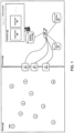
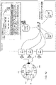
- FIG. 1 illustrates an example system architecture for an industrial IoT sensing system in both a field site 100 (e.g., shop floor) and a server site 101 (e.g., control / management center), in accordance with an example implementation.
- a field site 100 e.g., shop floor
- a server site 101 e.g., control / management center
- Server site 101 can include a server 103, a data lake 104, a communication switch 105 and a browsing device 106 (e.g., a personal computer).
- sensors 1-10 can include acoustic sensors and cameras to acquire acoustic signals and images from each local position. Then, the acoustic data, camera image, and other sensor information (e.g., sensor ID, accessorial sensor data) are transferred to one of the GWs 102-1, 102-2, 102-3 located on the field site 100 to facilitate the network connection to the sensors 1-10.
- the acoustic sensor data and camera image can be processed by main computing units configured in each sensor. Transferred data, images, and other information are stored in the data lake 104 to be processed according to the applications. For example, an application can be to overlay acoustic sensor data and camera images. Browsing device 106 can execute the applications on the data lake 104 to produce visualizations 107 on the camera data 108 and the sensor data 109.
- the visualization 107 involves providing an acoustic heatmap drawing to reduce manual costs and resources through the use of a novel sensor device independent of a GPS system.
- Example implementations described herein use novel methods to obtain sensor position information through using novel sensor devices to more easily facilitate the providing of an acoustic heatmap with improved productivity over related art approaches.
- FIGS. 2 and 3 illustrate an example application of holistic sensing with an acoustic sensor, in accordance with an example implementation.
- FIG. 2 and 3 illustrate an example of a drilldown analysis approach.
- a rough heatmap can be acquired from a single acoustic sensor that is enough to roughly search for abnormal events or machines as illustrated in the acoustic heatmap 107-1 of FIG. 2 .
- an abnormality e.g., temperatures, humidity, vibrations, etc. exceed preset threshold values
- a more detailed investigation can be operated with acoustic sensors array equipped in the sensor as illustrated in the acoustic heatmap 107-2 of FIG. 3 .
- the sensor device can be configured to calculate direction of arrival (DOA) of acoustic waves and facilitate beamforming functionalities through utilization of an acoustic sensor array as focused in particular directions to achieve spatial selectivity.
- DOA direction of arrival
- FIG. 4 shows an example element diagram of the sensor device in a field site, in accordance with an example implementation.
- sensor device 1 includes an acoustic sensors array 400 (e.g., an array configured with eight sensors as illustrated in FIG. 4 ), a 3-dimensional magnetometer/accelerometer 401 configured to detect the attitude of the sensor, a main computing/control unit (MCU) 402 made up of one or more hardware processors, a single acoustic sensor/speaker system 403 and an antenna radio 404.
- MCU main computing/control unit
- the sensor device 1 generates and transmits an acoustic wave signal 420 and a radio wave signal 410 through simultaneously utilizing acoustic sensor/speaker system 403 and antenna radio 404 according to the command from a server or computing device.
- MCU 402 can be configured to simultaneously transmit the acoustic wave signal from the acoustic sensor/speaker system 403 and the radio wave signal from the antenna 404 in response to a command received from the gateway. Such a command is transmitted from the server to the gateway and relayed to the sensor device 1 as described with respect to FIG. 5 and FIG. 7 .
- Antenna 404 is also used to communicate with the server 103 via one of the gateways 102-1, 102-2, 102-3 and can function as a network interface (I/F) for wireless communications between the server 103 and the sensor device.
- sensor devices can also be directly connected to the gateway 102-1, 102-2, 102-3 by a wired connection as well.
- cameras may also be included in the sensor devices to generate camera images.
- the acoustic sensor array of sensor device 2 detects the acoustic wave signal(s) to derive a direction of the detected acoustic wave through using direction of arrival (DOA) technique implemented on the MCU in accordance with the desired implementation.
- DOA direction of arrival
- the MCU can thereby determine a distance and a direction to another device (distance vector) that transmitted the acoustic wave signal and the radio wave signal.
- Such a process provides the relative distance vector from the sensor device 2 to sensor device 1 where sensor device 1 transmitted the acoustic wave signal and the radio wave signal.
- the sensor device 2 measures its own attitude using a 3-dimensional magnetometer and accelerometer.
- the accelerometer is used to measure tilt of the sensors.
- the 3-dimensional magnetometer is used to measure the orientation of the sensors. With the tilt and orientation values obtained from the 3-dimensional magnetometer and accelerometer, a coordinate system of all the relative distance vectors extracted from all the sensors can be maintained in a common format and frame of reference as the data processing in server 103. Once the sensor devices extract the distance vector to other sensor devices, the sensor devices can transmit the distance vector with tilt and orientation values to GWs.
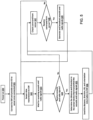
- FIG. 5 illustrates an example operational flow chart of a sensor device, in accordance with an example implementation.
- the flow diagram can be executed by the MCU of the sensor device. Once the sensor device is powered on at 500, the sensor device attempts to connect to a GW with a wireless or wired communication protocol at 501.
- the sensor device After connecting to the GW, the sensor device sends its sensor ID via the GW to the server 103.
- the sensor IDs are collected by the server 103, which is used to manage the position detection procedure for the sensor devices.
- the sensor device continues to transmit sensor data (acoustic raw data, pre-processed data, summarized data, and so on) at 502.
- the sensor device also waits for receiving acoustic and radio signals at 503 by using its acoustic sensor 403, acoustic sensors array 400, and antenna radio 404. If no acoustic or radio signals are received (No), the sensor device changes its operating state to check for commands from the server 103 at 507.
- the sensor device determines the distance and direction to the sensor device that transmitted the acoustic and radio signals through its MCU 402 at 505, and sends the distance, direction, tilt, and orientation data (e.g., which is derived from 3-dimensional magnetometer/accelerometer 401) information to a GW at 506.
- the sensor device determines the distance and direction to the sensor device that transmitted the acoustic and radio signals through its MCU 402 at 505, and sends the distance, direction, tilt, and orientation data (e.g., which is derived from 3-dimensional magnetometer/accelerometer 401) information to a GW at 506.
- the sensor device changes its operating state to check for commands from the server 103. If no command is received (No) at 508, then the sensor device will change its operation mode to execute the flow at 502 and 503 to transmit sensor data. Otherwise if the sensor device receives a command (Yes) at 508 from the server 103, the sensor device generates and broadcasts acoustic and radio signals simultaneously using the acoustic speaker and the antenna radio at 509, and continues to transmit sensor data again at 502.
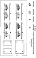
- FIGS. 6(a) and 6(b) illustrate an example of collected distance vectors from the sensor devices, in accordance with an example implementation.
- acoustic connections are illustrated, which depends on the position where the sensor device is located.
- ten acoustic connections are established across sensor devices 1, 3, 4, 5, 6, 7, 8, and 10, where the relative distance vectors are collected in server 103 as shown in FIG. 6(b) in detail.
- the distance vectors between each sensor device are implemented in an (x, y, z) form representing vector components in the Cartesian coordinate system.
- other formats can also be utilized according to the desired implementation, and the present disclosure is not limited thereto.
- FIG. 6(a) acoustic connections are illustrated, which depends on the position where the sensor device is located.
- ten acoustic connections are established across sensor devices 1, 3, 4, 5, 6, 7, 8, and 10, where the relative distance vectors are collected in server 103 as shown in FIG. 6(b) in detail.
- the distance vectors between each sensor device are implemented in an
- N/A indicates that the two corresponding sensor devices do not have a mutual acoustic connection. If a sensor device has the N/A entry in comparison with all of the other sensor devices, then it does not have an acoustic connection with other sensor devices. Accordingly, the server 103 can identify those devices that do not have an acoustic connection with other devices by referring to the distance vector table of FIG. 6(b) .
- FIG. 7 illustrates an example deployment procedure of the sensor devices to acquire position information for generating an acoustic heatmap, in accordance with an example implementation.
- the sensor devices are deployed on the field site according to user preference, while observing guidelines for acoustic communication distance (e.g., approximately 20 to 30 meters max for an example involving ultrasonic waves with spread spectrum), and the sensor devices are then powered up in order (e.g., according to their sensor ID, in response to a broadcasted power on command).
- all of the sensors devices connect to a GW, and provide their sensor IDs to server 103 as described with respect to the flow of FIG. 5 .
- the server 103 has a list of deployed sensor IDs, and sends a control command to cause each sensor device that have not broadcasted yet to simultaneously broadcast acoustic/radio waves at 702.
- Each sensor device which receives the command broadcasts acoustic and radio wave signals simultaneously at 703, as described with respect to FIG. 5 .
- the sensor devices which receive both of the wave signals through using its acoustic sensor, acoustic sensors array, and antenna radio calculates a distance and a direction through its MCU, and send to server 103 the distance, direction, tilt/orientation, and sensor ID information, as described in FIG. 5 .
- the server pauses for a short duration (e.g., for 2 or 3 seconds). This pause is utilized to prevent communication interference caused by acoustic wave signals, which can provide time division multiple propagations. Steps 700-705 of the flow are be repeated until all the sensor devices have broadcasted acoustic wave and radio wave simultaneously as determined at 706. If not all sensor devices have broadcasted (No), the flow proceeds back to 702, otherwise (Yes), the flow proceeds to 707.
- the server 103 determines the distance vector table as illustrated in FIG. 6(b) , with which the server can identify the sensor devices that have no acoustic connection with other devices at 707. If there is at least one sensor device which has no acoustic connection with other devices (No), the flow proceeds to 710 wherein the server 103 indicates to the browsing device 106 which of the sensor devices has no acoustic connection with other devices and therefore need to be relocated. The user can relocate the sensor device (e.g., move the sensor device to a new location or orientation within range to connect to another sensor device) and instruct the server 103 when the relocation is complete through browsing device 106, whereupon the flow can be reiterated at 702.
- the server 103 determines the distance vector table as illustrated in FIG. 6(b) , with which the server can identify the sensor devices that have no acoustic connection with other devices at 707. If there is at least one sensor device which has no acoustic connection with other devices (No), the flow proceeds to 710 wherein the server
- the server 103 calculates the relative position of each sensor device using distance, direction, tilt, and orientation information as gathered from each sensor device. Then, the server 103 derives the absolute position of all of the sensor devices at 709 based on a provision (e.g., by browsing device 106, by data from one of the sensor devices, etc.) of the specific position of one of the sensor devices (e.g., in (x, y, z) form by direct measurement, etc.).
- a provision e.g., by browsing device 106, by data from one of the sensor devices, etc.
- the specific position of one of the sensor devices e.g., in (x, y, z) form by direct measurement, etc.
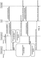
- FIG. 8 illustrates an example of communication time procedure between sensor devices, GWs, and server based on the deployment procedure of FIG. 7 . Specifically, FIG. 8 illustrates an example iteration of the overall system in time order, regarding how and when each system element initiates its procedures from FIG. 7 .
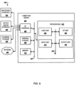
- FIG. 9 illustrates an example computing environment with an example computer device suitable for use in some example implementations, such as for facilitating functionality for the server 103 and/or browsing device 106 as illustrated in FIG. 1 .
- Computer device 905 in computing environment 900 can include one or more processing units, cores, or processors 910, memory 915 (e.g., RAM, ROM, and/or the like), internal storage 920 (e.g., magnetic, optical, solid state storage, and/or organic), and/or I/O interface 925, any of which can be coupled on a communication mechanism or bus 930 for communicating information or embedded in the computer device 905.
- I/O interface 925 is also configured to receive images from cameras or provide images to projectors or displays, depending on the desired implementation.
- Computer device 905 can be communicatively coupled to input/user interface 935 and output device/interface 940. Either one or both of input/user interface 935 and output device/interface 940 can be a wired or wireless interface and can be detachable.
- Input/user interface 935 may include any device, component, sensor, or interface, physical or virtual, that can be used to provide input (e.g., buttons, touch-screen interface, keyboard, a pointing/cursor control, microphone, camera, braille, motion sensor, optical reader, and/or the like).
- Output device/interface 940 may include a display, television, monitor, printer, speaker, braille, or the like.
- input/user interface 935 and output device/interface 940 can be embedded with or physically coupled to the computer device 905.
- other computer devices may function as or provide the functions of input/user interface 935 and output device/interface 940 for a computer device 905.
- Examples of computer device 905 may include, but are not limited to, highly mobile devices (e.g., smartphones, devices in vehicles and other machines, devices carried by humans and animals, and the like), mobile devices (e.g., tablets, notebooks, laptops, personal computers, portable televisions, radios, and the like), and devices not designed for mobility (e.g., desktop computers, other computers, information kiosks, televisions with one or more processors embedded therein and/or coupled thereto, radios, and the like).
- highly mobile devices e.g., smartphones, devices in vehicles and other machines, devices carried by humans and animals, and the like
- mobile devices e.g., tablets, notebooks, laptops, personal computers, portable televisions, radios, and the like
- devices not designed for mobility e.g., desktop computers, other computers, information kiosks, televisions with one or more processors embedded therein and/or coupled thereto, radios, and the like.
- Computer device 905 can be communicatively coupled (e.g., via I/O interface 925) to external storage 945 and network 950 for communicating with any number of networked components, devices, and systems, including one or more computer devices of the same or different configuration.
- Computer device 905 or any connected computer device can be functioning as, providing services of, or referred to as a server, client, thin server, general machine, special-purpose machine, or another label.
- I/O interface 925 can include, but is not limited to, wired and/or wireless interfaces using any communication or I/O protocols or standards (e.g., Ethernet, 802.11x, Universal System Bus, WiMax, modem, a cellular network protocol, and the like) for communicating information to and/or from at least all the connected components, devices, and network in computing environment 900.
- Network 950 can be any network or combination of networks (e.g., the Internet, local area network, wide area network, a telephonic network, a cellular network, satellite network, and the like).
- Computer device 905 can use and/or communicate using computer-usable or computer-readable media, including transitory media and non-transitory media.
- Transitory media include transmission media (e.g., metal cables, fiber optics), signals, carrier waves, and the like.
- Non-transitory media include magnetic media (e.g., disks and tapes), optical media (e.g., CD ROM, digital video disks, Blu-ray disks), solid state media (e.g., RAM, ROM, flash memory, solid-state storage), and other non-volatile storage or memory.
- Computer device 905 can be used to implement techniques, methods, applications, processes, or computer-executable instructions in some example computing environments.
- Computer-executable instructions can be retrieved from transitory media, and stored on and retrieved from non-transitory media.
- the executable instructions can originate from one or more of any programming, scripting, and machine languages (e.g., C, C++, C#, Java, Visual Basic, Python, Perl, JavaScript, and others).
- Processor(s) 910 can execute under any operating system (OS) (not shown), in a native or virtual environment.
- OS operating system
- One or more applications can be deployed that include logic unit 960, application programming interface (API) unit 965, input unit 970, output unit 975, and inter-unit communication mechanism 995 for the different units to communicate with each other, with the OS, and with other applications (not shown).
- API application programming interface
- the described units and elements can be varied in design, function, configuration, or implementation and are not limited to the descriptions provided.
- API unit 965 when information or an execution instruction is received by API unit 965, it may be communicated to one or more other units (e.g., logic unit 960, input unit 970, output unit 975).
- logic unit 960 may be configured to control the information flow among the units and direct the services provided by API unit 965, input unit 970, output unit 975, in some example implementations described above. For example, the flow of one or more processes or implementations may be controlled by logic unit 960 alone or in conjunction with API unit 965.
- the input unit 970 may be configured to obtain input for the calculations described in the example implementations
- the output unit 975 may be configured to provide output based on the calculations described in example implementations.
- Processor(s) 910 can be configured to execute the flow diagrams as illustrated in FIGS. 7 and 8 and can be configured to transmit a command to the plurality of devices to simultaneously broadcast an acoustic wave signal and a radio wave signal as described with respect to FIGS. 4 , 5 and 7 ; receive information regarding detected acoustic wave signals and detected radio wave signals, and 3-dimensional magnetometer measurements from each of the plurality of devices as described with respect to FIG. 7 ; and for the information indicative of each of the plurality of devices having at least one acoustic connection with another one of the plurality of devices, determining a position for each of the plurality of devices as described with respect to FIG. 6(b) and FIG. 7 .
- processor(s) 910 can be configured to determine such situations based on identifying which devices did not transmit their information regarding detected acoustic wave signals and radio wave signals and/or not receiving an acknowledgement to the issued command, depending on the desired implementation.
- processor(s) 910 can be configured to, for ones of the plurality of devices not simultaneously broadcasting the acoustic wave signal and the radio wave signal in response to the command, retransmit the command to the ones of the plurality of devices as described in FIG. 7 .
- processor(s) 910 can detect such a situation from the distance vector table of FIG. 6(b) and can be configured to indicate the one or more of the plurality of devices not having at least one acoustic connection with another one of the plurality of devices for relocation as described in FIG. 7 .
- acoustic heatmaps as illustrated in FIGS. 2 and 3 can be generated based on the determined positions of each of the plurality of devices by processor(s) 910.
- Processor(s) 910 can refer to distance vector table FIG. 6(b) and generate a heatmap based on the number of vectors between sensor devices, or through other methods in accordance with the desired implementation.
- processor(s) 910 can be configured to determine the position for each of the plurality of devices by calculating a relative position of the each of the plurality of devices based on the 3-dimensional magnetometer measurements, and distance information and direction information from the information regarding the detected acoustic wave signals and the detected radio wave signals and deriving absolute positions for the plurality of devices based on the calculation of the relative position.
- processor(s) 910 can be configured to pause before transmission of the command based on a setting.
- the setting can be preset (e.g., 2-3 seconds) or calculated through any desired implementation.
- Memory 915 can be configured to manage information received from the plurality of sensor devices, such as distance and direction between sensor devices, tilt and orientation measurements from 3-dimensional magnetometers and accelerometers, and depending on the desired implementation, data regarding acoustic signals and radio wave signals. From such information, memory 915 can be configured to store information regarding the acoustic connections between sensor devices as illustrated in FIGS. 6(a) and 6(b) , and acoustic heatmaps as illustrated in FIGS. 2 and 3 . Depending on the desired implementation, such information can also be stored in the data lake 104.
- sensor devices are assumed to be deployed in an arbitrary arrangement in the factory shop floor to cover overall shop floor.
- the positions of the assets e.g., processing machines
- the asset positions are converted into a relative position from the sensor devices' viewpoint in order to identify the direction where they turn the beams in their fields of acoustic vision.
- the acoustic sensor arrays of sensor devices become able to make their focuses on the assets which users want to investigate. Accordingly, this approach can facilitate various analytics such as machine condition classification (monitoring), machine diagnosis, dictation recognition using the state-of-the-art artificial intelligence (AI)/machine learning technologies using extremely low noise acoustic data.
- AI state-of-the-art artificial intelligence
- FIG. 11 illustrates an example of overall diagram of shop floor with an assignment of assets such as machine A, B, C, and D. Further, sensor devices having an acoustic array and a center camera 1203 are shown, whose deployment positions can be arbitrary. In FIG. 11 , the sensor devices are deployed in grid type manner for simpler explanation.
- FIG. 12 an example of a system diagram which facilitates the application is shown, wherein the camera 1203 is installed in the center of the sensor devices and "asset-image correspondence table" 1300 is inside the data lake 104 (graphical user interface (GUI) 1400 is also shown).
- GUI graphical user interface
- FIG. 13 shows an example of "Asset-Image correspondence table" 1300 which converts camera images as shown in camera image 1100 of FIG. 11 into asset IDs (or labels or names or so).
- GUI 1400 can support the uses to indicate assets which they want to investigate using filter field, and select the exact position of the asset using the asset selection field where the overall shop floor diagram is shown.
- GUI for asset condition monitoring shown in FIG. 14 once users indicate the asset which they want to investigate, analyzed / processed results are shown in the table in the bottom portion of the GUI.
- an application that involves establishing beamforming functionality on the device as described in FIGS. 4 and 12 , using the system as described in FIG. 12 , the algorithms as described in FIGS. 5 , 7 and 8 , and the position information of the assets managed by the systems.
- the application further involves converting position information of assets into the beamforming direction; and facilitating acoustic condition monitoring of assets with AI or machine learning techniques.
- the application can also involve an managing in a data lake asset-image correspondence table which shows the correspondence between asset images prepared in advance and asset ID by which users can identify the assets as illustrated in FIG. 13 ; converting asset images prepared in advance to pixel position of the assets in the video camera with image recognition technique, and converting pixel position of the assets to beam direction of acoustic microphone array.
- Such example implementations further involve a GUI which shows for an asset a selection field of a synthesized video camera movie, a filter field, and a table field showing the analyzed results of the asset, and provides selection and filter functionalities of assets or groups of assets through input to the movie (e.g., a click or tap) and through the input in the filter field (e.g., checked boxes).
- a GUI which shows for an asset a selection field of a synthesized video camera movie, a filter field, and a table field showing the analyzed results of the asset, and provides selection and filter functionalities of assets or groups of assets through input to the movie (e.g., a click or tap) and through the input in the filter field (e.g., checked boxes).
- Example implementations may also relate to an apparatus for performing the operations herein.
- This apparatus may be specially constructed for the required purposes, or it may include one or more general-purpose computers selectively activated or reconfigured by one or more computer programs.
- Such computer programs may be stored in a computer readable medium, such as a computer-readable storage medium or a computer-readable signal medium.
- a computer-readable storage medium may involve tangible mediums such as, but not limited to optical disks, magnetic disks, read-only memories, random access memories, solid state devices and drives, or any other types of tangible or non-transitory media suitable for storing electronic information.
- a computer readable signal medium may include mediums such as carrier waves.
- the algorithms and displays presented herein are not inherently related to any particular computer or other apparatus.
- Computer programs can involve pure software implementations that involve instructions that perform the operations of the desired implementation.
- the operations described above can be performed by hardware, software, or some combination of software and hardware.
- Various aspects of the example implementations may be implemented using circuits and logic devices (hardware), while other aspects may be implemented using instructions stored on a machine-readable medium (software), which if executed by a processor, would cause the processor to perform a method to carry out implementations of the present application.
- some example implementations of the present application may be performed solely in hardware, whereas other example implementations may be performed solely in software.
- the various functions described can be performed in a single unit, or can be spread across a number of components in any number of ways.
- the methods may be executed by a processor, such as a general purpose computer, based on instructions stored on a computer-readable medium. If desired, the instructions can be stored on the medium in a compressed and/or encrypted format.
Landscapes
- Physics & Mathematics (AREA)
- General Physics & Mathematics (AREA)
- Health & Medical Sciences (AREA)
- Engineering & Computer Science (AREA)
- Otolaryngology (AREA)
- Acoustics & Sound (AREA)
- General Health & Medical Sciences (AREA)
- Signal Processing (AREA)
- Condensed Matter Physics & Semiconductors (AREA)
- Biochemistry (AREA)
- Life Sciences & Earth Sciences (AREA)
- Chemical & Material Sciences (AREA)
- Analytical Chemistry (AREA)
- Immunology (AREA)
- Pathology (AREA)
- Radar, Positioning & Navigation (AREA)
- Remote Sensing (AREA)
- Automation & Control Theory (AREA)
- Measurement Of Velocity Or Position Using Acoustic Or Ultrasonic Waves (AREA)
- Position Fixing By Use Of Radio Waves (AREA)
- Testing And Monitoring For Control Systems (AREA)
Claims (13)
- Dispositif configuré pour calculer une direction d'arrivée (DOA) d'ondes acoustiques et pour permettre des fonctionnalités de formation de faisceau, comprenant :un réseau (400) de capteurs (1-10) configurés pour détecter des signaux d'onde acoustique ;un magnétomètre tridimensionnel (401) ;une antenne (404) configurée pour émettre et recevoir des signaux d'onde radio ;un haut-parleur acoustique (403) configuré pour émettre des signaux d'onde acoustique ; etun processeur (910), configuré pour :émettre simultanément un signal d'onde acoustique provenant du haut-parleur acoustique (403) et un signal d'onde radio provenant de l'antenne (404) en réponse à un ordre reçu depuis la passerelle (102-1, 102-2, 102-3) ;détecter un autre signal d'onde acoustique provenant du réseau (400) de capteurs acoustiques (1-10) et un autre signal d'onde radio provenant de l'antenne (404) ; etémettre, vers la passerelle (102-1, 102-2, 102-3), des informations concernant ledit autre signal d'onde acoustique détecté et ledit autre signal d'onde radio détecté, et des mesurages provenant du magnétomètre tridimensionnel (401), les informations comprenant une distance déterminée en multipliant une différence entre des temps d'arrivée dudit autre signal d'onde acoustique et dudit autre signal d'onde radio par une vitesse acoustique dans l'air.
- Dispositif selon la revendication 1, dans lequel le dispositif est configuré pour conduire la détection dudit autre signal d'onde acoustique provenant du réseau de capteurs acoustiques (1-10) et dudit autre signal d'onde radio provenant de l'antenne (404) tandis que le dispositif est en rotation.
- Dispositif selon la revendication 1, dans lequel les mesurages provenant du magnétomètre tridimensionnel (401) comprennent des mesurages d'orientation du dispositif, et dans lequel le processeur (910) est configuré pour émettre des mesurages d'inclinaison du dispositif vers la passerelle (102-1, 102-2, 102-3).
- Dispositif selon la revendication 1, dans lequel le processeur (901) est configuré, pour la détection dudit autre signal d'onde acoustique provenant du réseau (400) de capteurs acoustiques (1-10) et dudit autre signal d'onde radio provenant de l'antenne (404), pour :déterminer une direction vers un autre dispositif qui émet ledit autre signal d'onde acoustique et ledit autre signal d'onde radio ;émettre la direction déterminée à titre d'informations concernant ledit autre signal d'onde acoustique détecté et ledit autre signal d'onde radio détecté.
- Système, comprenant :une pluralité de dispositifs configurés pour calculer une direction d'arrivée (DOA) d'ondes acoustiques et pour permettre des fonctionnalités de formation de faisceau ; etun serveur (103) configuré pour interagir avec la pluralité de dispositifs, le serveur comprenant :
un processeur configuré pour :émettre un ordre vers chacun de la pluralité de dispositifs donnant instruction au dispositif de diffuser simultanément un signal d'onde acoustique et un signal d'onde radio en réponse à l'ordre ;recevoir des informations concernant des signaux d'onde acoustique détectés et des signaux d'onde radio détectés, et des mesurages de magnétomètre tridimensionnel provenant de chacun de la pluralité de dispositifs, les informations comprenant une distance déterminée en multipliant une différence entre des temps d'arrivée du signal d'onde acoustique et du signal d'onde radio au niveau d'un dispositif capteur particulier, par une vitesse acoustique dans l'air ; etpour les informations indiquant que chacun de la pluralité de dispositifs a au moins une connexion acoustique avec un autre de la pluralité de dispositifs, déterminer une position pour chacun de la pluralité de dispositifs. - Système selon la revendication 5, dans lequel, pour quelques-uns de la pluralité de dispositifs qui ne diffusent pas simultanément le signal d'onde acoustique et le signal d'onde radio en réponse à l'ordre, le processeur est configuré pour réémettre l'ordre vers lesdits quelques-uns de la pluralité de dispositifs.
- Système selon la revendication 5, dans lequel, pour les informations indiquant qu'un ou plusieurs de la pluralité de dispositifs n'ont pas au moins une connexion acoustique avec un autre de la pluralité de dispositifs, le processeur est configuré pour indiquer lesdits un ou plusieurs de la pluralité de dispositifs qui n'ont pas au moins une connexion acoustique avec un autre de la pluralité de dispositifs pour relocalisation.
- Système selon la revendication 5, dans lequel le processeur est configuré pour déterminer la position pour chacun de la pluralité de dispositifs au moyen d'un calcul d'une position relative de chacun de la pluralité de dispositifs sur la base des mesurages de magnétomètre tridimensionnel, et des informations de distance et des informations de direction à partir des informations concernant les signaux d'onde acoustique détectés et les signaux d'onde radio détectés et une dérivation de positions absolues pour la pluralité de dispositifs sur la base du calcul de la position relative.
- Procédé, comprenant les étapes consistant à :émettre, via un serveur configuré pour interagir avec une pluralité de dispositifs, un ordre vers chacun de la pluralité de dispositifs donnant instruction au dispositif de diffuser simultanément un signal d'onde acoustique et un signal d'onde radio en réponse à l'ordre ;recevoir des informations concernant des signaux d'onde acoustique détectés et des signaux d'onde radio détectés, et des mesurages de magnétomètre tridimensionnel provenant de chacun de la pluralité de dispositifs, les informations comprenant une distance déterminée en multipliant une différence entre des temps d'arrivée du signal d'onde acoustique et du signal d'onde radio au niveau d'un dispositif capteur particulier, par une vitesse acoustique dans l'air ; etpour les informations indiquant que chacun de la pluralité de dispositifs a au moins une connexion acoustique à un autre de la pluralité de dispositifs, déterminer une position pour chacun de la pluralité de dispositifs.
- Procédé selon la revendication 9, comprenant en outre l'étape consistant à, pour quelques-uns de la pluralité de dispositifs qui ne diffusent pas simultanément le signal d'onde acoustique et le signal d'onde radio en réponse à l'ordre, réémettre l'ordre vers lesdits quelques-uns de la pluralité de dispositifs.
- Procédé selon la revendication 9, comprenant en outre l'étape consistant à, pour les informations indiquant qu'un ou plusieurs de la pluralité de dispositifs n'ont pas au moins une connexion acoustique avec un autre de la pluralité de dispositifs, indiquer lesdits un ou plusieurs de la pluralité de dispositifs qui n'ont pas au moins une connexion acoustique avec un autre de la pluralité de dispositifs pour relocalisation.
- Procédé selon la revendication 9, dans lequel l'étape consistant à déterminer la position pour chacun de la pluralité de dispositifs comprend :de calculer une position relative de chacun de la pluralité de dispositifs sur la base des mesurages de magnétomètre tridimensionnel, et des informations de distance et des informations de direction à partir des informations concernant les signaux d'onde acoustique détectés et les signaux d'onde radio détectés, etde dériver des positions absolues pour la pluralité de dispositifs sur la base du calcul de la position relative.
- Procédé selon la revendication 9, dans lequel chacun de la pluralité de dispositifs comprend une caméra vidéo et un réseau de microphones acoustiques, le procédé comprenant en outre les étapes consistant à :gérer, dans un lac de données configuré pour stocker des informations, une table de correspondance actif-image qui montre la correspondance entre des images d'actifs et un identifiant d'actif (ID) ;convertir des images d'actifs en positions de pixels des actifs dans la caméra vidéo par reconnaissance d'image,convertir les positions de pixels des actifs en une direction de faisceau du réseau de microphones acoustiques ; etfournir une interface utilisateur graphique (GUI) configurée pour :montrer, pour chacun des actifs, un champ de sélection destiné à fournir un film de caméra vidéo synthétisé, un champ de filtre, et un champ de table montrant les résultats analysés de chacun des actifs, etfournir des fonctionnalités de sélection et de filtre des actifs ou de groupes d'actifs via une entrée reçue sur le film et le champ de filtre.
Applications Claiming Priority (1)
| Application Number | Priority Date | Filing Date | Title |
|---|---|---|---|
| US16/166,596 US10852276B2 (en) | 2018-10-22 | 2018-10-22 | Holistic sensing method and system |
Publications (2)
| Publication Number | Publication Date |
|---|---|
| EP3644627A1 EP3644627A1 (fr) | 2020-04-29 |
| EP3644627B1 true EP3644627B1 (fr) | 2023-02-22 |
Family
ID=68296109
Family Applications (1)
| Application Number | Title | Priority Date | Filing Date |
|---|---|---|---|
| EP19204073.1A Active EP3644627B1 (fr) | 2018-10-22 | 2019-10-18 | Système et procédé de détection holistique |
Country Status (4)
| Country | Link |
|---|---|
| US (1) | US10852276B2 (fr) |
| EP (1) | EP3644627B1 (fr) |
| JP (1) | JP6815461B2 (fr) |
| CN (1) | CN111076768B (fr) |
Families Citing this family (1)
| Publication number | Priority date | Publication date | Assignee | Title |
|---|---|---|---|---|
| WO2021123251A1 (fr) * | 2019-12-20 | 2021-06-24 | Gn Hearing A/S | Appareil de communication pour utilisateur effectuant une mission et procédés associés |
Family Cites Families (20)
| Publication number | Priority date | Publication date | Assignee | Title |
|---|---|---|---|---|
| JP2006220636A (ja) * | 2004-07-27 | 2006-08-24 | Matsushita Electric Works Ltd | 音波センサ |
| US7433266B2 (en) * | 2004-09-16 | 2008-10-07 | Vanderbilt University | Acoustic source localization system and applications of the same |
| JP4100416B2 (ja) * | 2005-01-12 | 2008-06-11 | 松下電工株式会社 | 位置検出システム |
| JP5456259B2 (ja) * | 2008-01-30 | 2014-03-26 | 日野自動車株式会社 | 溶接検査方法および装置 |
| WO2011013418A1 (fr) * | 2009-07-31 | 2011-02-03 | 日本電気株式会社 | Dispositif de détection de position, procédé de détection de position, objet mobile et récepteur |
| JP2012133250A (ja) * | 2010-12-24 | 2012-07-12 | Sony Corp | 音情報表示装置、音情報表示方法およびプログラム |
| US9408011B2 (en) | 2011-12-19 | 2016-08-02 | Qualcomm Incorporated | Automated user/sensor location recognition to customize audio performance in a distributed multi-sensor environment |
| EP2620050B1 (fr) * | 2012-01-25 | 2016-07-27 | Honda Research Institute Europe GmbH | Système, procédé et appareil pour l'adaptation non supervisée de la perception d'une tondeuse autonome |
| WO2014012028A2 (fr) * | 2012-07-12 | 2014-01-16 | Robert Bosch Gmbh | Système et procédé d'aide intéractive pour tâches automatisées à intelligence intégrée |
| US20150264505A1 (en) * | 2014-03-13 | 2015-09-17 | Accusonus S.A. | Wireless exchange of data between devices in live events |
| US9581490B2 (en) * | 2014-04-17 | 2017-02-28 | Saudi Arabian Oil Company | Pipeline integrity monitoring using fiber optics |
| JP6480118B2 (ja) * | 2014-07-17 | 2019-03-06 | 株式会社トルク | 空間に情報を記録する方法及びそのシステム |
| US10420515B2 (en) * | 2015-06-15 | 2019-09-24 | Vital Labs, Inc. | Method and system for acquiring data for assessment of cardiovascular disease |
| US20170076156A1 (en) * | 2015-09-14 | 2017-03-16 | Logitech Europe S.A. | Automatically determining camera location and determining type of scene |
| CN113287958A (zh) * | 2015-10-30 | 2021-08-24 | 金伯利-克拉克环球有限公司 | 产品使用情况声学确定系统 |
| US10034066B2 (en) * | 2016-05-02 | 2018-07-24 | Bao Tran | Smart device |
| US10481925B2 (en) * | 2016-07-01 | 2019-11-19 | Intel Corporation | Dynamic user interface in machine-to-machine systems |
| WO2018052791A1 (fr) | 2016-09-13 | 2018-03-22 | Walmart Apollo, Llc | Système et procédés pour identifier une action sur la base d'une détection par le son |
| US10409548B2 (en) * | 2016-09-27 | 2019-09-10 | Grabango Co. | System and method for differentially locating and modifying audio sources |
| CN108663658B (zh) * | 2017-03-30 | 2020-11-03 | 北京京东尚科信息技术有限公司 | 用于终端的室内定位方法和装置 |
-
2018
- 2018-10-22 US US16/166,596 patent/US10852276B2/en active Active
-
2019
- 2019-10-10 JP JP2019186469A patent/JP6815461B2/ja not_active Expired - Fee Related
- 2019-10-18 EP EP19204073.1A patent/EP3644627B1/fr active Active
- 2019-10-21 CN CN201911001295.3A patent/CN111076768B/zh not_active Expired - Fee Related
Also Published As
| Publication number | Publication date |
|---|---|
| CN111076768B (zh) | 2022-03-11 |
| CN111076768A (zh) | 2020-04-28 |
| JP6815461B2 (ja) | 2021-01-20 |
| US20200124572A1 (en) | 2020-04-23 |
| JP2020067451A (ja) | 2020-04-30 |
| US10852276B2 (en) | 2020-12-01 |
| EP3644627A1 (fr) | 2020-04-29 |
Similar Documents
| Publication | Publication Date | Title |
|---|---|---|
| US9477891B2 (en) | Surveillance system and method based on accumulated feature of object | |
| WO2017148155A1 (fr) | Système et procédé de charge sans fil | |
| US9894536B2 (en) | Motion-controlled device for supporting planning, deployment or operation of a wireless network | |
| EP2856266B1 (fr) | Inspection d'objets dans une installation industrielle | |
| US11758081B2 (en) | Server and method for displaying 3D tour comparison | |
| EP2975860A1 (fr) | Dispositif de correction de la vitesse du son | |
| US20230104775A1 (en) | Human robot collaboration for flexible and adaptive robot learning | |
| US20170187991A1 (en) | Indoor positioning system using beacons and video analytics | |
| CN119363820A (zh) | 基于边缘计算的无人机多维感知智能巡检预警系统及方法 | |
| EP3644627B1 (fr) | Système et procédé de détection holistique | |
| US20170188138A1 (en) | Microphone beamforming using distance and enrinonmental information | |
| JP6108925B2 (ja) | 撮像装置、フォーカス調整システム、フォーカス指示装置、フォーカス調整方法、及びプログラム | |
| US20170061990A1 (en) | Image and audio reproduction device and method | |
| KR20230168929A (ko) | 객체를 검출하기 위한 방법 및 이를 지원하는 전자 장치 | |
| US10783902B1 (en) | Adaptive acoustic sensing method and system | |
| US11810387B2 (en) | Location system and method | |
| US11842452B2 (en) | Portable display device with overlaid virtual information | |
| WO2019037517A1 (fr) | Dispositif électronique mobile et procédé de traitement de tâche dans une zone de tâche | |
| WO2019097412A1 (fr) | Système et procédé de surveillance des performances multimédia d'un équipement | |
| US10785563B1 (en) | Omni-directional audible noise source localization apparatus | |
| US12520037B1 (en) | Interactive method to guide a human to a precise location based on a wider image of the area around the location | |
| CN113894788B (zh) | 视觉伺服方法和视觉伺服系统 | |
| US12553313B2 (en) | Drone-based acquisition of wellhead data and wireless choke adjustment | |
| US20240264045A1 (en) | Robust predictive maintenance method for machinery using measured vibration data and estimated sound data | |
| WO2021236089A1 (fr) | Système et procédé d'identification d'emplacements de salariés utilisant une rfid et une caméra |
Legal Events
| Date | Code | Title | Description |
|---|---|---|---|
| PUAI | Public reference made under article 153(3) epc to a published international application that has entered the european phase |
Free format text: ORIGINAL CODE: 0009012 |
|
| STAA | Information on the status of an ep patent application or granted ep patent |
Free format text: STATUS: REQUEST FOR EXAMINATION WAS MADE |
|
| 17P | Request for examination filed |
Effective date: 20200128 |
|
| AK | Designated contracting states |
Kind code of ref document: A1 Designated state(s): AL AT BE BG CH CY CZ DE DK EE ES FI FR GB GR HR HU IE IS IT LI LT LU LV MC MK MT NL NO PL PT RO RS SE SI SK SM TR |
|
| AX | Request for extension of the european patent |
Extension state: BA ME |
|
| STAA | Information on the status of an ep patent application or granted ep patent |
Free format text: STATUS: EXAMINATION IS IN PROGRESS |
|
| 17Q | First examination report despatched |
Effective date: 20201203 |
|
| GRAP | Despatch of communication of intention to grant a patent |
Free format text: ORIGINAL CODE: EPIDOSNIGR1 |
|
| STAA | Information on the status of an ep patent application or granted ep patent |
Free format text: STATUS: GRANT OF PATENT IS INTENDED |
|
| RIC1 | Information provided on ipc code assigned before grant |
Ipc: H04R 1/40 20060101ALN20220912BHEP Ipc: H04R 29/00 20060101AFI20220912BHEP |
|
| INTG | Intention to grant announced |
Effective date: 20220928 |
|
| GRAS | Grant fee paid |
Free format text: ORIGINAL CODE: EPIDOSNIGR3 |
|
| GRAA | (expected) grant |
Free format text: ORIGINAL CODE: 0009210 |
|
| STAA | Information on the status of an ep patent application or granted ep patent |
Free format text: STATUS: THE PATENT HAS BEEN GRANTED |
|
| AK | Designated contracting states |
Kind code of ref document: B1 Designated state(s): AL AT BE BG CH CY CZ DE DK EE ES FI FR GB GR HR HU IE IS IT LI LT LU LV MC MK MT NL NO PL PT RO RS SE SI SK SM TR |
|
| REG | Reference to a national code |
Ref country code: GB Ref legal event code: FG4D |
|
| REG | Reference to a national code |
Ref country code: CH Ref legal event code: EP |
|
| REG | Reference to a national code |
Ref country code: DE Ref legal event code: R096 Ref document number: 602019025473 Country of ref document: DE |
|
| REG | Reference to a national code |
Ref country code: AT Ref legal event code: REF Ref document number: 1550271 Country of ref document: AT Kind code of ref document: T Effective date: 20230315 Ref country code: IE Ref legal event code: FG4D |
|
| REG | Reference to a national code |
Ref country code: LT Ref legal event code: MG9D |
|
| REG | Reference to a national code |
Ref country code: NL Ref legal event code: MP Effective date: 20230222 |
|
| REG | Reference to a national code |
Ref country code: AT Ref legal event code: MK05 Ref document number: 1550271 Country of ref document: AT Kind code of ref document: T Effective date: 20230222 |
|
| PG25 | Lapsed in a contracting state [announced via postgrant information from national office to epo] |
Ref country code: RS Free format text: LAPSE BECAUSE OF FAILURE TO SUBMIT A TRANSLATION OF THE DESCRIPTION OR TO PAY THE FEE WITHIN THE PRESCRIBED TIME-LIMIT Effective date: 20230222 Ref country code: PT Free format text: LAPSE BECAUSE OF FAILURE TO SUBMIT A TRANSLATION OF THE DESCRIPTION OR TO PAY THE FEE WITHIN THE PRESCRIBED TIME-LIMIT Effective date: 20230622 Ref country code: NO Free format text: LAPSE BECAUSE OF FAILURE TO SUBMIT A TRANSLATION OF THE DESCRIPTION OR TO PAY THE FEE WITHIN THE PRESCRIBED TIME-LIMIT Effective date: 20230522 Ref country code: NL Free format text: LAPSE BECAUSE OF FAILURE TO SUBMIT A TRANSLATION OF THE DESCRIPTION OR TO PAY THE FEE WITHIN THE PRESCRIBED TIME-LIMIT Effective date: 20230222 Ref country code: LV Free format text: LAPSE BECAUSE OF FAILURE TO SUBMIT A TRANSLATION OF THE DESCRIPTION OR TO PAY THE FEE WITHIN THE PRESCRIBED TIME-LIMIT Effective date: 20230222 Ref country code: LT Free format text: LAPSE BECAUSE OF FAILURE TO SUBMIT A TRANSLATION OF THE DESCRIPTION OR TO PAY THE FEE WITHIN THE PRESCRIBED TIME-LIMIT Effective date: 20230222 Ref country code: HR Free format text: LAPSE BECAUSE OF FAILURE TO SUBMIT A TRANSLATION OF THE DESCRIPTION OR TO PAY THE FEE WITHIN THE PRESCRIBED TIME-LIMIT Effective date: 20230222 Ref country code: ES Free format text: LAPSE BECAUSE OF FAILURE TO SUBMIT A TRANSLATION OF THE DESCRIPTION OR TO PAY THE FEE WITHIN THE PRESCRIBED TIME-LIMIT Effective date: 20230222 Ref country code: AT Free format text: LAPSE BECAUSE OF FAILURE TO SUBMIT A TRANSLATION OF THE DESCRIPTION OR TO PAY THE FEE WITHIN THE PRESCRIBED TIME-LIMIT Effective date: 20230222 |
|
| PG25 | Lapsed in a contracting state [announced via postgrant information from national office to epo] |
Ref country code: SE Free format text: LAPSE BECAUSE OF FAILURE TO SUBMIT A TRANSLATION OF THE DESCRIPTION OR TO PAY THE FEE WITHIN THE PRESCRIBED TIME-LIMIT Effective date: 20230222 Ref country code: PL Free format text: LAPSE BECAUSE OF FAILURE TO SUBMIT A TRANSLATION OF THE DESCRIPTION OR TO PAY THE FEE WITHIN THE PRESCRIBED TIME-LIMIT Effective date: 20230222 Ref country code: IS Free format text: LAPSE BECAUSE OF FAILURE TO SUBMIT A TRANSLATION OF THE DESCRIPTION OR TO PAY THE FEE WITHIN THE PRESCRIBED TIME-LIMIT Effective date: 20230622 Ref country code: GR Free format text: LAPSE BECAUSE OF FAILURE TO SUBMIT A TRANSLATION OF THE DESCRIPTION OR TO PAY THE FEE WITHIN THE PRESCRIBED TIME-LIMIT Effective date: 20230523 Ref country code: FI Free format text: LAPSE BECAUSE OF FAILURE TO SUBMIT A TRANSLATION OF THE DESCRIPTION OR TO PAY THE FEE WITHIN THE PRESCRIBED TIME-LIMIT Effective date: 20230222 |
|
| PG25 | Lapsed in a contracting state [announced via postgrant information from national office to epo] |
Ref country code: SM Free format text: LAPSE BECAUSE OF FAILURE TO SUBMIT A TRANSLATION OF THE DESCRIPTION OR TO PAY THE FEE WITHIN THE PRESCRIBED TIME-LIMIT Effective date: 20230222 Ref country code: RO Free format text: LAPSE BECAUSE OF FAILURE TO SUBMIT A TRANSLATION OF THE DESCRIPTION OR TO PAY THE FEE WITHIN THE PRESCRIBED TIME-LIMIT Effective date: 20230222 Ref country code: EE Free format text: LAPSE BECAUSE OF FAILURE TO SUBMIT A TRANSLATION OF THE DESCRIPTION OR TO PAY THE FEE WITHIN THE PRESCRIBED TIME-LIMIT Effective date: 20230222 Ref country code: DK Free format text: LAPSE BECAUSE OF FAILURE TO SUBMIT A TRANSLATION OF THE DESCRIPTION OR TO PAY THE FEE WITHIN THE PRESCRIBED TIME-LIMIT Effective date: 20230222 Ref country code: CZ Free format text: LAPSE BECAUSE OF FAILURE TO SUBMIT A TRANSLATION OF THE DESCRIPTION OR TO PAY THE FEE WITHIN THE PRESCRIBED TIME-LIMIT Effective date: 20230222 |
|
| REG | Reference to a national code |
Ref country code: DE Ref legal event code: R097 Ref document number: 602019025473 Country of ref document: DE |
|
| PG25 | Lapsed in a contracting state [announced via postgrant information from national office to epo] |
Ref country code: SK Free format text: LAPSE BECAUSE OF FAILURE TO SUBMIT A TRANSLATION OF THE DESCRIPTION OR TO PAY THE FEE WITHIN THE PRESCRIBED TIME-LIMIT Effective date: 20230222 |
|
| PLBE | No opposition filed within time limit |
Free format text: ORIGINAL CODE: 0009261 |
|
| STAA | Information on the status of an ep patent application or granted ep patent |
Free format text: STATUS: NO OPPOSITION FILED WITHIN TIME LIMIT |
|
| PGFP | Annual fee paid to national office [announced via postgrant information from national office to epo] |
Ref country code: GB Payment date: 20231025 Year of fee payment: 5 |
|
| 26N | No opposition filed |
Effective date: 20231123 |
|
| PG25 | Lapsed in a contracting state [announced via postgrant information from national office to epo] |
Ref country code: SI Free format text: LAPSE BECAUSE OF FAILURE TO SUBMIT A TRANSLATION OF THE DESCRIPTION OR TO PAY THE FEE WITHIN THE PRESCRIBED TIME-LIMIT Effective date: 20230222 |
|
| PGFP | Annual fee paid to national office [announced via postgrant information from national office to epo] |
Ref country code: FR Payment date: 20231023 Year of fee payment: 5 Ref country code: DE Payment date: 20231031 Year of fee payment: 5 |
|
| PG25 | Lapsed in a contracting state [announced via postgrant information from national office to epo] |
Ref country code: IT Free format text: LAPSE BECAUSE OF FAILURE TO SUBMIT A TRANSLATION OF THE DESCRIPTION OR TO PAY THE FEE WITHIN THE PRESCRIBED TIME-LIMIT Effective date: 20230222 Ref country code: MC Free format text: LAPSE BECAUSE OF FAILURE TO SUBMIT A TRANSLATION OF THE DESCRIPTION OR TO PAY THE FEE WITHIN THE PRESCRIBED TIME-LIMIT Effective date: 20230222 |
|
| REG | Reference to a national code |
Ref country code: CH Ref legal event code: PL |
|
| REG | Reference to a national code |
Ref country code: BE Ref legal event code: MM Effective date: 20231031 |
|
| PG25 | Lapsed in a contracting state [announced via postgrant information from national office to epo] |
Ref country code: LU Free format text: LAPSE BECAUSE OF NON-PAYMENT OF DUE FEES Effective date: 20231018 |
|
| PG25 | Lapsed in a contracting state [announced via postgrant information from national office to epo] |
Ref country code: LU Free format text: LAPSE BECAUSE OF NON-PAYMENT OF DUE FEES Effective date: 20231018 |
|
| PG25 | Lapsed in a contracting state [announced via postgrant information from national office to epo] |
Ref country code: CH Free format text: LAPSE BECAUSE OF NON-PAYMENT OF DUE FEES Effective date: 20231031 |
|
| PG25 | Lapsed in a contracting state [announced via postgrant information from national office to epo] |
Ref country code: CH Free format text: LAPSE BECAUSE OF NON-PAYMENT OF DUE FEES Effective date: 20231031 |
|
| PG25 | Lapsed in a contracting state [announced via postgrant information from national office to epo] |
Ref country code: BE Free format text: LAPSE BECAUSE OF NON-PAYMENT OF DUE FEES Effective date: 20231031 |
|
| PG25 | Lapsed in a contracting state [announced via postgrant information from national office to epo] |
Ref country code: IE Free format text: LAPSE BECAUSE OF NON-PAYMENT OF DUE FEES Effective date: 20231018 |
|
| PG25 | Lapsed in a contracting state [announced via postgrant information from national office to epo] |
Ref country code: IE Free format text: LAPSE BECAUSE OF NON-PAYMENT OF DUE FEES Effective date: 20231018 |
|
| PG25 | Lapsed in a contracting state [announced via postgrant information from national office to epo] |
Ref country code: BG Free format text: LAPSE BECAUSE OF FAILURE TO SUBMIT A TRANSLATION OF THE DESCRIPTION OR TO PAY THE FEE WITHIN THE PRESCRIBED TIME-LIMIT Effective date: 20230222 |
|
| PG25 | Lapsed in a contracting state [announced via postgrant information from national office to epo] |
Ref country code: BG Free format text: LAPSE BECAUSE OF FAILURE TO SUBMIT A TRANSLATION OF THE DESCRIPTION OR TO PAY THE FEE WITHIN THE PRESCRIBED TIME-LIMIT Effective date: 20230222 |
|
| REG | Reference to a national code |
Ref country code: DE Ref legal event code: R119 Ref document number: 602019025473 Country of ref document: DE |
|
| GBPC | Gb: european patent ceased through non-payment of renewal fee |
Effective date: 20241018 |
|
| PG25 | Lapsed in a contracting state [announced via postgrant information from national office to epo] |
Ref country code: DE Free format text: LAPSE BECAUSE OF NON-PAYMENT OF DUE FEES Effective date: 20250501 |
|
| PG25 | Lapsed in a contracting state [announced via postgrant information from national office to epo] |
Ref country code: GB Free format text: LAPSE BECAUSE OF NON-PAYMENT OF DUE FEES Effective date: 20241018 |
|
| PG25 | Lapsed in a contracting state [announced via postgrant information from national office to epo] |
Ref country code: FR Free format text: LAPSE BECAUSE OF NON-PAYMENT OF DUE FEES Effective date: 20241031 |
|
| PG25 | Lapsed in a contracting state [announced via postgrant information from national office to epo] |
Ref country code: CY Free format text: LAPSE BECAUSE OF FAILURE TO SUBMIT A TRANSLATION OF THE DESCRIPTION OR TO PAY THE FEE WITHIN THE PRESCRIBED TIME-LIMIT; INVALID AB INITIO Effective date: 20191018 |
|
| PG25 | Lapsed in a contracting state [announced via postgrant information from national office to epo] |
Ref country code: HU Free format text: LAPSE BECAUSE OF FAILURE TO SUBMIT A TRANSLATION OF THE DESCRIPTION OR TO PAY THE FEE WITHIN THE PRESCRIBED TIME-LIMIT; INVALID AB INITIO Effective date: 20191018 |
|
| PG25 | Lapsed in a contracting state [announced via postgrant information from national office to epo] |
Ref country code: TR Free format text: LAPSE BECAUSE OF FAILURE TO SUBMIT A TRANSLATION OF THE DESCRIPTION OR TO PAY THE FEE WITHIN THE PRESCRIBED TIME-LIMIT Effective date: 20230222 |