EP3644697A1 - Module de refroidissement pour un appareil de commande de véhicule, appareil de commande de véhicule doté d'un module de refroidissement et procédé de refroidissement à eau d'une unité de commande de véhicule - Google Patents
Module de refroidissement pour un appareil de commande de véhicule, appareil de commande de véhicule doté d'un module de refroidissement et procédé de refroidissement à eau d'une unité de commande de véhicule Download PDFInfo
- Publication number
- EP3644697A1 EP3644697A1 EP19197158.9A EP19197158A EP3644697A1 EP 3644697 A1 EP3644697 A1 EP 3644697A1 EP 19197158 A EP19197158 A EP 19197158A EP 3644697 A1 EP3644697 A1 EP 3644697A1
- Authority
- EP
- European Patent Office
- Prior art keywords
- cooling
- bimetal
- vehicle control
- heat sink
- cooling fins
- Prior art date
- Legal status (The legal status is an assumption and is not a legal conclusion. Google has not performed a legal analysis and makes no representation as to the accuracy of the status listed.)
- Withdrawn
Links
- 238000001816 cooling Methods 0.000 title abstract description 117
- 238000000034 method Methods 0.000 title abstract description 15
- XLYOFNOQVPJJNP-UHFFFAOYSA-N water Substances O XLYOFNOQVPJJNP-UHFFFAOYSA-N 0.000 title abstract description 10
- 239000002826 coolant Substances 0.000 abstract description 33
- 230000001419 dependent effect Effects 0.000 abstract description 5
- LYCAIKOWRPUZTN-UHFFFAOYSA-N Ethylene glycol Chemical compound OCCO LYCAIKOWRPUZTN-UHFFFAOYSA-N 0.000 description 12
- 239000004020 conductor Substances 0.000 description 8
- 238000012546 transfer Methods 0.000 description 8
- 229910052751 metal Inorganic materials 0.000 description 7
- 239000002184 metal Substances 0.000 description 7
- 238000005452 bending Methods 0.000 description 6
- 150000002739 metals Chemical class 0.000 description 4
- 238000013473 artificial intelligence Methods 0.000 description 3
- AEDZKIACDBYJLQ-UHFFFAOYSA-N ethane-1,2-diol;hydrate Chemical compound O.OCCO AEDZKIACDBYJLQ-UHFFFAOYSA-N 0.000 description 3
- 239000000203 mixture Substances 0.000 description 3
- 102100034112 Alkyldihydroxyacetonephosphate synthase, peroxisomal Human genes 0.000 description 2
- RYGMFSIKBFXOCR-UHFFFAOYSA-N Copper Chemical compound [Cu] RYGMFSIKBFXOCR-UHFFFAOYSA-N 0.000 description 2
- 101000799143 Homo sapiens Alkyldihydroxyacetonephosphate synthase, peroxisomal Proteins 0.000 description 2
- 229910052782 aluminium Inorganic materials 0.000 description 2
- XAGFODPZIPBFFR-UHFFFAOYSA-N aluminium Chemical compound [Al] XAGFODPZIPBFFR-UHFFFAOYSA-N 0.000 description 2
- 238000000848 angular dependent Auger electron spectroscopy Methods 0.000 description 2
- 229910052802 copper Inorganic materials 0.000 description 2
- 239000010949 copper Substances 0.000 description 2
- 230000017525 heat dissipation Effects 0.000 description 2
- 239000004065 semiconductor Substances 0.000 description 2
- 238000003466 welding Methods 0.000 description 2
- 238000013528 artificial neural network Methods 0.000 description 1
- 230000002457 bidirectional effect Effects 0.000 description 1
- 239000012809 cooling fluid Substances 0.000 description 1
- 230000006735 deficit Effects 0.000 description 1
- 238000009795 derivation Methods 0.000 description 1
- 238000013461 design Methods 0.000 description 1
- 238000001514 detection method Methods 0.000 description 1
- 238000011161 development Methods 0.000 description 1
- 230000018109 developmental process Effects 0.000 description 1
- 238000000265 homogenisation Methods 0.000 description 1
- 238000009434 installation Methods 0.000 description 1
- 239000000463 material Substances 0.000 description 1
- 239000012528 membrane Substances 0.000 description 1
- 238000012856 packing Methods 0.000 description 1
- 238000012545 processing Methods 0.000 description 1
- 230000001105 regulatory effect Effects 0.000 description 1
- 238000005096 rolling process Methods 0.000 description 1
- 230000000930 thermomechanical effect Effects 0.000 description 1
- 238000002604 ultrasonography Methods 0.000 description 1
Images


Classifications
-
- H—ELECTRICITY
- H05—ELECTRIC TECHNIQUES NOT OTHERWISE PROVIDED FOR
- H05K—PRINTED CIRCUITS; CASINGS OR CONSTRUCTIONAL DETAILS OF ELECTRIC APPARATUS; MANUFACTURE OF ASSEMBLAGES OF ELECTRICAL COMPONENTS
- H05K7/00—Constructional details common to different types of electric apparatus
- H05K7/20—Modifications to facilitate cooling, ventilating, or heating
- H05K7/20845—Modifications to facilitate cooling, ventilating, or heating for automotive electronic casings
- H05K7/20872—Liquid coolant without phase change
-
- F—MECHANICAL ENGINEERING; LIGHTING; HEATING; WEAPONS; BLASTING
- F28—HEAT EXCHANGE IN GENERAL
- F28F—DETAILS OF HEAT-EXCHANGE AND HEAT-TRANSFER APPARATUS, OF GENERAL APPLICATION
- F28F13/00—Arrangements for modifying heat-transfer, e.g. increasing, decreasing
- F28F13/06—Arrangements for modifying heat-transfer, e.g. increasing, decreasing by affecting the pattern of flow of the heat-exchange media
- F28F13/08—Arrangements for modifying heat-transfer, e.g. increasing, decreasing by affecting the pattern of flow of the heat-exchange media by varying the cross-section of the flow channels
-
- G—PHYSICS
- G05—CONTROLLING; REGULATING
- G05D—SYSTEMS FOR CONTROLLING OR REGULATING NON-ELECTRIC VARIABLES
- G05D23/00—Control of temperature
- G05D23/01—Control of temperature without auxiliary power
- G05D23/02—Control of temperature without auxiliary power with sensing element expanding and contracting in response to changes of temperature
- G05D23/08—Control of temperature without auxiliary power with sensing element expanding and contracting in response to changes of temperature with bimetallic element
-
- H—ELECTRICITY
- H05—ELECTRIC TECHNIQUES NOT OTHERWISE PROVIDED FOR
- H05K—PRINTED CIRCUITS; CASINGS OR CONSTRUCTIONAL DETAILS OF ELECTRIC APPARATUS; MANUFACTURE OF ASSEMBLAGES OF ELECTRICAL COMPONENTS
- H05K7/00—Constructional details common to different types of electric apparatus
- H05K7/20—Modifications to facilitate cooling, ventilating, or heating
- H05K7/20218—Modifications to facilitate cooling, ventilating, or heating using a liquid coolant without phase change in electronic enclosures
- H05K7/20272—Accessories for moving fluid, for expanding fluid, for connecting fluid conduits, for distributing fluid, for removing gas or for preventing leakage, e.g. pumps, tanks or manifolds
-
- H—ELECTRICITY
- H05—ELECTRIC TECHNIQUES NOT OTHERWISE PROVIDED FOR
- H05K—PRINTED CIRCUITS; CASINGS OR CONSTRUCTIONAL DETAILS OF ELECTRIC APPARATUS; MANUFACTURE OF ASSEMBLAGES OF ELECTRICAL COMPONENTS
- H05K7/00—Constructional details common to different types of electric apparatus
- H05K7/20—Modifications to facilitate cooling, ventilating, or heating
- H05K7/20218—Modifications to facilitate cooling, ventilating, or heating using a liquid coolant without phase change in electronic enclosures
- H05K7/20281—Thermal management, e.g. liquid flow control
-
- F—MECHANICAL ENGINEERING; LIGHTING; HEATING; WEAPONS; BLASTING
- F01—MACHINES OR ENGINES IN GENERAL; ENGINE PLANTS IN GENERAL; STEAM ENGINES
- F01P—COOLING OF MACHINES OR ENGINES IN GENERAL; COOLING OF INTERNAL-COMBUSTION ENGINES
- F01P2050/00—Applications
- F01P2050/30—Circuit boards
-
- F—MECHANICAL ENGINEERING; LIGHTING; HEATING; WEAPONS; BLASTING
- F02—COMBUSTION ENGINES; HOT-GAS OR COMBUSTION-PRODUCT ENGINE PLANTS
- F02D—CONTROLLING COMBUSTION ENGINES
- F02D41/00—Electrical control of supply of combustible mixture or its constituents
- F02D41/20—Output circuits, e.g. for controlling currents in command coils
- F02D2041/202—Output circuits, e.g. for controlling currents in command coils characterised by the control of the circuit
- F02D2041/2065—Output circuits, e.g. for controlling currents in command coils characterised by the control of the circuit the control being related to the coil temperature
-
- F—MECHANICAL ENGINEERING; LIGHTING; HEATING; WEAPONS; BLASTING
- F28—HEAT EXCHANGE IN GENERAL
- F28F—DETAILS OF HEAT-EXCHANGE AND HEAT-TRANSFER APPARATUS, OF GENERAL APPLICATION
- F28F13/00—Arrangements for modifying heat-transfer, e.g. increasing, decreasing
- F28F2013/005—Thermal joints
- F28F2013/008—Variable conductance materials; Thermal switches
-
- F—MECHANICAL ENGINEERING; LIGHTING; HEATING; WEAPONS; BLASTING
- F28—HEAT EXCHANGE IN GENERAL
- F28F—DETAILS OF HEAT-EXCHANGE AND HEAT-TRANSFER APPARATUS, OF GENERAL APPLICATION
- F28F2255/00—Heat exchanger elements made of materials having special features or resulting from particular manufacturing processes
- F28F2255/04—Heat exchanger elements made of materials having special features or resulting from particular manufacturing processes comprising shape memory alloys or bimetallic elements
-
- G—PHYSICS
- G05—CONTROLLING; REGULATING
- G05D—SYSTEMS FOR CONTROLLING OR REGULATING NON-ELECTRIC VARIABLES
- G05D23/00—Control of temperature
- G05D23/19—Control of temperature characterised by the use of electric means
- G05D23/275—Control of temperature characterised by the use of electric means with sensing element expanding, contracting, or fusing in response to changes of temperature
- G05D23/27535—Details of the sensing element
- G05D23/2754—Details of the sensing element using bimetallic element
Definitions
- the invention relates to a cooling module for a vehicle control unit according to claim 1. Furthermore, the invention relates to a vehicle control unit according to claim 7 with a cooling module. In addition, the invention relates to a method according to claim 10 for water cooling a vehicle control unit.
- Vehicle control units in the English electronic control unit, abbreviated ECU, are also known from the prior art.
- Vehicle control units include hardware platforms for the logical processing of input signals in order to provide logic and / or power levels as regulating or control signals for vehicle control.
- vehicle control devices that regulate and control driver assistance systems and / or automated / autonomous driving comprise supercomputing hardware platforms.
- supercomputing platforms include multi-core processors comprising several central processor units and several graphics processors. In a multi-core processor, multiple cores are arranged on a single chip, that is to say a semiconductor component.
- Multi-core processors achieve higher computing power and are less expensive to implement in a chip compared to multi-processor systems, in which each individual core is arranged in a processor socket and the individual processor sockets are arranged on a motherboard.
- the multi-core processors process an artificial intelligence, for example artificial neural networks, in order to be able to react intuitively to new driving situations like a human driver. This is achieved using a large computing power. This creates a lot of heat that has to be dissipated by cooling. Because of its high specific heat capacity, water is a particularly suitable coolant for vehicle control units.
- a requirement for vehicle control units is functionality in the temperature range of essentially -40 ° C to + 9x ° C.
- water has a low suitability for cold.
- water is added to the coolant to add ethylene glycol reduce the volume fraction of ethylene glycol to an ice flake point of the water-ethylene glycol mixture.
- ethylene glycol volume fraction of over 50% is required.
- this high proportion of ethylene glycol leads to a high dependency between the temperature and viscosity of the coolant. As the temperature drops, especially below -10 ° C, the coolant becomes more viscous and the viscosity increases. This leads to an undesirable drop in volume flow and pressure increase.
- the cooling is not performant. Compensation of these fluid-mechanical parameters, volume flow and pressure, could be managed with a more powerful cooling pump. However, this would involve additional effort and costs.
- the invention has for its object to improve the cooling of vehicle control units.
- the invention solves this problem by a cooling module for a vehicle control device with the features of claim 1. Furthermore, the invention solves the problem by a vehicle control device with the features of claim 7. Furthermore, the invention solves the problem by a method for cooling a water Vehicle control unit having the features of claim 10.
- the cooling module according to the invention for a vehicle control unit comprises a heat sink. Furthermore, the cooling module comprises connections in order to conduct a coolant through the heat sink. In addition, the cooling module comprises a turbulence insert arranged in the heat sink. The turbulence insert comprises at least first cooling fins. The cooling module further comprises at least one first bimetal arranged in the heat sink. The bimetal is arranged to adjust the at least first cooling fins as a function of a temperature-dependent change in shape of the at least first bimetal.
- Cooling modules are structural units which consist of various components for cooling a device, for example a vehicle control unit, the components being dimensioned accordingly with regard to the devices to be cooled and the given installation space.
- the heat sink is 210 mm long and 140 mm wide.
- the ports are preferably an inlet and an outlet valve.
- the inlet valve is arranged on an inlet side of the heat sink.
- the outlet valve is arranged on an outlet side of the heat sink opposite the inlet side.
- the coolant flows through the heat sink essentially in a straight line.
- the inlet valve and outlet valve are arranged on one side of the heat sink. In this arrangement, the coolant flows through the heat sink essentially in a U-shape.
- the coolant is preferably a water-ethylene glycol mixture.
- Another component of the cooling module are the cooling fins to improve the heat transfer.
- the cooling fins or additional components of the cooling module form turbulence inserts for swirling the coolant.
- the cooling fins are made of metal, for example aluminum and / or copper.
- a bimetal comprises two metals with different coefficients of linear expansion.
- the two metals are bonded to one another in a material or form-fitting manner. If you connect the two ends of the two metals, for example by riveting, spot welding or rolling, the temperature-dependent different extension leads to a bending of the bimetal.
- the temperature-dependent bending of the bimetal and the contacting of the bimetal to the cooling fins results in the result that the bimetal serves as an actuator for the adjustment of the cooling fins.
- the bimetal together with the cooling fins acts like a membrane or a valve in relation to the coolant. At low temperatures, the bimetal bends and deforms the cooling fins.
- the bimetal presses the cooling fins in the direction of the housing wall of the heat sink.
- the valve is now open. At high temperatures, the bimetal takes on a straight, flat state. The cooling fins are essentially completely drawn into the passage channel of the coolant. The valve is now closed.
- the coolant flow is limited to a specified size.
- an essentially constant volume flow becomes constant Pressure loss in the heat sink over a temperature range of -40 ° C to + 9x ° C provided. This creates a dynamic turbulence insert that prevents the coolant from clumping together at low temperatures, in particular below -10 ° C. Overall, the cooling performance of the cooling module is improved by the bimetal.
- the bimetal has the particular advantage that it generates large forces.
- the relatively large masses of the cooling fins can thus be adjusted and at the same time the associated friction can be overcome.
- Another advantage of bimetal is its longevity due to its low-wear functionality and its suitability as a heat transfer medium.
- the bimetal is preferably contacted thermally on a housing edge of the heat sink in such a way that the thermal conductivity is as good as possible.
- This can be a metal to metal connection, preferably a welded-on solution.
- the heat flow not only runs through the cooling fluid, but also through the housing.
- the at least first cooling fins are preferably arranged transversely to the longitudinal direction of the heat sink.
- the central axis of the at least first bimetal is arranged parallel to the longitudinal direction of the heat sink. Both sides of the at least first bimetal are connected to the heat sink in addition to the central axis.
- a first end of each of the first cooling fins is connected to a first side or a second side of the heat sink opposite the first side.
- a second end of the first cooling fins is arranged on the first bimetal for adjusting the first cooling fins by bending the first bimetal as a function of temperature.
- the first side of the heat sink is preferably its underside.
- the second side of the heat sink is preferably the top thereof.
- the second end of the first cooling fins lies loosely on the first bimetal, slides on the first bimetal or is riveted or welded to the first bimetal, for example.
- the cooling module comprises second cooling fins.
- the second cooling fins are arranged transversely to the longitudinal direction of the heat sink.
- the cooling module comprises a second bimetal arranged in the cooling body.
- the second bimetal is arranged parallel to the first bimetal.
- a first end of each of the second cooling fins is connected to the second side or the first side of the heat sink.
- a second end of the second cooling fins is arranged on the second bimetal analogously to the first cooling fins, for adjusting the second cooling fins by bending the second bimetal as a function of temperature.
- the first cooling fins are connected to the underside of the heat sink, for example.
- the second cooling fins are connected to the top of the heat sink, for example.
- the first bimetal and the second bimetal preferably centered in the heat sink, are arranged between the first cooling fins and the second cooling fins. The volume flow of the coolant can thus be improved.
- the first bimetal bends in the opposite direction to the second bimetal. At low temperatures, the first bimetal, for example, presses the first cooling fins towards the bottom of the heat sink.
- the second bimetal for example, presses the second cooling fins towards the top of the heat sink at low temperatures.
- first cooling fins and / or the second cooling fins are each welded or riveted to the heat sink at their first end.
- the first cooling fins and / or the second cooling fins are preferably wave-shaped. This improves the swirling of the coolant and increases the surface area of the first cooling fins and / or the second cooling fins.
- the first bimetal and / or the second bimetal preferably have the shape of a sheet or are particularly preferably lamellar.
- the lamellar design improves the adjustability of the first cooling fins and / or the second cooling fins. This improves the cooling process.
- a vehicle control unit comprises a cooling module according to the invention.
- the vehicle control unit is preferably an AD / ADAS domain ECU with artificial intelligence, that is to say a vehicle control unit for driver assistance system, called advanced driver assistance systems in English, or for automated or autonomous driving functions, called automated or autonomous driving in English. Domain means that the vehicle control unit controls the entire area for ADAS / AD, in particular the environment detection by environment sensors such as camera, radar, lidar, ultrasound, microphones, the derivation of a real driving situation, the trajectory planning and the vehicle guidance.
- the hardware platform of the vehicle control unit is designed to process the input signals using artificial intelligence.
- the hardware platform includes in particular graphics processors that are designed for parallel computing, preferably in the form of multi-core processors.
- the cooling module is preferably flanged to the vehicle control unit in order to ensure heat transfer.
- a heat conductor for improving the heat transfer is advantageously between the vehicle control unit and the cooling module.
- the heat conductor is another component of the cooling module, for example.
- the heat conductor can be a so-called heat spreader, with the task of reducing the heat flow density over a larger area, for example from 23 x 23 mm area to a palm size.
- a heat spreader is a thermo-mechanical component, the special geometry of which reduces the heat flow density of a heat source to the heat sink by means of a heat-conductive body, for example comprising aluminum or copper. In the simplest case, this body is comparable to an upside-down pyramid.
- the heat source is on the lower tip and the heat sink is on the upper surface.
- the heat conductor is preferably riveted or welded to the first side of the heat sink.
- the first Cooling fins are also riveted or welded to the first side of the heat sink. By riveting or welding the heat conductor and the first cooling fins, the heat transfer is better than through a loosely sliding connection.
- the cooling module or the vehicle control unit are, for example, integrated in a cooling circuit of a vehicle, in which further vehicle components and / or further control units are also integrated.
- the cooling circuit is secured against failures by the turbulence insert with bimetal, which provides high-performance cooling without clumping of the coolant.
- the system availability is thus improved and impairment of the further vehicle components and / or further control devices is at least reduced.
- the cooling module and / or the vehicle control unit are preferably arranged in a housing.
- the housing protects the cooling module from mechanical stresses, weather influences and other external influences.
- the method achieves water cooling with an essentially constant volume flow and constant pressure loss in the temperature range from -40 ° C to + 9x ° C. A clumping of the coolant at low temperatures, especially below -10 ° C, is avoided.
- the cooling module 10 in Fig. 1 comprises a heat sink 11.
- the heat sink 11 has a first side 11a.
- the first side 11a is, for example, an underside of the heat sink 11, compare Fig. 3 .
- the heat sink 11 has a second side 11b.
- the second side 11b is, for example, an upper side of the heat sink 11, compare Fig. 3 .
- a coolant is passed through the heat sink 11.
- the coolant is, for example, a water-ethylene glycol mixture.
- the heat sink 11 forms, for example, channels through which the coolant is passed.
- a U-shaped channel is shown as an example.
- additional channels or protruding pins are alternatively attached for the targeted conduction of the coolant through the heat sink 11 or for homogenization of the coolant in the heat sink 11 Fig. 2
- the bidirectional arrows shown within the heat sink 11 clarify the direction of expansion of a first bimetal 14a and a second bimetal 14b between the respective riveted or welded end points thereof, see also Fig. 3 .
- the cooling module 10 comprises a first connection 12a. The coolant is conducted into the heat sink 11 via the first connection 12a.
- the first connection 12a is designed as an inlet valve.
- the cooling module 10 comprises a second connection 12b.
- the coolant is led out of the heat sink 11 via the second connection 12b.
- the second connection 12b is designed as an outlet valve.
- the cooling module 10 is flanged onto a vehicle control unit 20 in the figures, a heat conductor 15 being arranged between the cooling module 10 and the vehicle control unit 20.
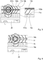
- Fig. 3 shows first cooling fins 13a and second cooling fins 13b.
- the first cooling fins 13a and the second cooling fins 13b are arranged one above the other and each have a wave or S shape, the shape of the second cooling fins 13b being mirrored vertically relative to the shape of the first cooling fins 13a.
- the first cooling fins 13a are welded to a first end 131a on the first side 11a of the heat sink 11, for example, and slide with a second end 132a on a first bimetal 14a.
- the second cooling fins 13b are, for example, welded to a first end 131b on the second side 11b of the heat sink 11 and slide with a second end 132b on a second bimetal 14b.
- first cooling fins 13a, second cooling fins 13b, the first bimetal 14a and the second bimetal 14b forms a valve due to the temperature-dependent bending of the first bimetal 14a and the second bimetal 14b.
- the valve is closed. This corresponds to the state at temperatures above a threshold.
- the valve is open. This corresponds to the condition at temperatures below the threshold.
- the threshold is -10 ° C.
- the heat transfer of the vehicle control unit 20 to the coolant via the heat conductor 15 takes place only via the first bimetal 14a and the first cooling fins 13a, but not via the second bimetal 14b with the second cooling fins 13b. At low temperatures, high-performance heat transfer is not yet required.
- Fig. 5 symbolizes the method according to the invention for water cooling the vehicle control unit 20.
- the coolant is passed through the cooling module 10.
- the cooling module 10 is in thermal contact with the vehicle control unit 20.
- a turbulent flow of the coolant through the cooling module 10 is generated by means of the turbulence insert.
- the volume flow of the coolant through the cooling module 10 is changed by the change in shape of the first bimetal 14a and the second bimetal 14b depending on the temperature.
Landscapes
- Engineering & Computer Science (AREA)
- Microelectronics & Electronic Packaging (AREA)
- Physics & Mathematics (AREA)
- Thermal Sciences (AREA)
- General Physics & Mathematics (AREA)
- Automation & Control Theory (AREA)
- Mechanical Engineering (AREA)
- General Engineering & Computer Science (AREA)
- Cooling Or The Like Of Semiconductors Or Solid State Devices (AREA)
- Cooling Or The Like Of Electrical Apparatus (AREA)
Applications Claiming Priority (1)
| Application Number | Priority Date | Filing Date | Title |
|---|---|---|---|
| DE102018218049.0A DE102018218049B4 (de) | 2018-10-22 | 2018-10-22 | Kühlmodul für ein Fahrzeug-Steuergerät, Fahrzeug-Steuergerät mit einem Kühlmodul und Verfahren zur Wasserkühlung eines Fahrzeug-Steuergeräts |
Publications (1)
| Publication Number | Publication Date |
|---|---|
| EP3644697A1 true EP3644697A1 (fr) | 2020-04-29 |
Family
ID=67997338
Family Applications (1)
| Application Number | Title | Priority Date | Filing Date |
|---|---|---|---|
| EP19197158.9A Withdrawn EP3644697A1 (fr) | 2018-10-22 | 2019-09-13 | Module de refroidissement pour un appareil de commande de véhicule, appareil de commande de véhicule doté d'un module de refroidissement et procédé de refroidissement à eau d'une unité de commande de véhicule |
Country Status (3)
| Country | Link |
|---|---|
| US (1) | US11209844B2 (fr) |
| EP (1) | EP3644697A1 (fr) |
| DE (1) | DE102018218049B4 (fr) |
Families Citing this family (3)
| Publication number | Priority date | Publication date | Assignee | Title |
|---|---|---|---|---|
| EP4092720A1 (fr) * | 2021-05-20 | 2022-11-23 | Aptiv Technologies Limited | Dissipateur de chaleur |
| DE102023211440A1 (de) * | 2023-11-17 | 2025-05-22 | Schaeffler Technologies AG & Co. KG | Leistungselektronik-Kühler, Leistungselektronikvorrichtung und Inverter |
| DE102024201708B3 (de) | 2024-02-23 | 2025-06-26 | Schaeffler Technologies AG & Co. KG | Elektronik-Kühler, Elektronikvorrichtung und Inverter mit einem Elektronik-Kühler |
Citations (3)
| Publication number | Priority date | Publication date | Assignee | Title |
|---|---|---|---|---|
| JPS5844755A (ja) * | 1981-09-11 | 1983-03-15 | Nec Corp | 強制空冷用ヒ−トシンク |
| EP3032580A1 (fr) * | 2014-03-14 | 2016-06-15 | Fuji Electric Co., Ltd. | Dispositif de refroidissement et dispositif à semi-conducteurs comportant ledit dispositif de refroidissement |
| DE102016106750A1 (de) * | 2015-04-15 | 2017-02-09 | Ford Global Technologies, Llc | Leistungswechselrichter für ein fahrzeug |
Family Cites Families (17)
| Publication number | Priority date | Publication date | Assignee | Title |
|---|---|---|---|---|
| US3513881A (en) * | 1967-07-24 | 1970-05-26 | Garrett Corp | Flow regulator having thrust recovery |
| CH524224A (de) * | 1970-11-18 | 1972-06-15 | Bbc Brown Boveri & Cie | Verfahren und Einrichtung zur Regelung der Durchflussmenge eines Fluides in einer Rohrleitung eines Kernkraftwerkes |
| US3831396A (en) * | 1971-08-19 | 1974-08-27 | Aeronautical Res Ass Of Prince | Self-regulating thermal protection system for heated surfaces |
| US6016250A (en) * | 1998-01-30 | 2000-01-18 | Credence Systems Corporation | Self-balancing thermal control device for integrated circuits |
| US6330157B1 (en) * | 1999-12-21 | 2001-12-11 | International Business Machines Corporation | Variable thermal exchanger and method thereof |
| US20020134542A1 (en) * | 2001-03-20 | 2002-09-26 | Unsworth John Duncan | Heat exchanger with passive in-line temperature control |
| DE112008000873T5 (de) * | 2007-05-28 | 2010-04-29 | Aisin Aw Co., Ltd. | Kühlvorrichtung für eine Steuereinheit für ein Automatikgetriebe |
| US20090321044A1 (en) * | 2008-06-30 | 2009-12-31 | Alcatel-Lucent Technologies Inc. | Active heat sink designs |
| CN104159436A (zh) * | 2014-08-15 | 2014-11-19 | 韩百萍 | 一种自清洁散热翅片散热器 |
| US10557671B2 (en) * | 2015-01-16 | 2020-02-11 | Hamilton Sundstrand Corporation | Self-regulating heat exchanger |
| DE102015007799A1 (de) * | 2015-06-19 | 2016-12-22 | Mann + Hummel Gmbh | Wärmeübertragerelement, Wärmeübertrager und Energiespeicher |
| US10267578B2 (en) * | 2015-08-04 | 2019-04-23 | Raytheon Company | Shape memory material based thermal coupler/decoupler and method |
| US9841772B2 (en) * | 2015-12-03 | 2017-12-12 | Te Connectivity Corporation | Temperature responsive thermal bridge |
| US11008943B2 (en) * | 2016-08-31 | 2021-05-18 | Unison Industries, Llc | Fan casing assembly with cooler and method of moving |
| US10004156B2 (en) * | 2016-09-26 | 2018-06-19 | Asia Vital Components Co., Ltd. | Heat radiation fin structure |
| US10730645B2 (en) * | 2017-04-21 | 2020-08-04 | The Boeing Company | System and method for shape memory alloy thermal interface |
| US10573575B2 (en) * | 2017-08-28 | 2020-02-25 | Intel Corporation | Semiconductor package with thermal fins |
-
2018
- 2018-10-22 DE DE102018218049.0A patent/DE102018218049B4/de active Active
-
2019
- 2019-09-13 EP EP19197158.9A patent/EP3644697A1/fr not_active Withdrawn
- 2019-10-21 US US16/659,167 patent/US11209844B2/en active Active
Patent Citations (3)
| Publication number | Priority date | Publication date | Assignee | Title |
|---|---|---|---|---|
| JPS5844755A (ja) * | 1981-09-11 | 1983-03-15 | Nec Corp | 強制空冷用ヒ−トシンク |
| EP3032580A1 (fr) * | 2014-03-14 | 2016-06-15 | Fuji Electric Co., Ltd. | Dispositif de refroidissement et dispositif à semi-conducteurs comportant ledit dispositif de refroidissement |
| DE102016106750A1 (de) * | 2015-04-15 | 2017-02-09 | Ford Global Technologies, Llc | Leistungswechselrichter für ein fahrzeug |
Also Published As
| Publication number | Publication date |
|---|---|
| DE102018218049B4 (de) | 2020-08-13 |
| US20200128699A1 (en) | 2020-04-23 |
| US11209844B2 (en) | 2021-12-28 |
| DE102018218049A1 (de) | 2020-04-23 |
Similar Documents
| Publication | Publication Date | Title |
|---|---|---|
| EP3644697A1 (fr) | Module de refroidissement pour un appareil de commande de véhicule, appareil de commande de véhicule doté d'un module de refroidissement et procédé de refroidissement à eau d'une unité de commande de véhicule | |
| DE112014004308T5 (de) | Flache Wärmetauschröhre sowie Wärmeträger-Heizvorrichtung und Klimatisierungseinrichtung für ein selbige nutzendes Fahrzeug | |
| DE112015006353T5 (de) | Kühlvorrichtung, leistungswandlervorrichtung und kühlsystem | |
| DE112022004158T5 (de) | Halbleitervorrichtung | |
| DE102017222350A1 (de) | Wärmetauscher für eine doppelseitige kühlung von elektronikmodulen | |
| DE112017003768T5 (de) | Kühlvorrichtung | |
| DE112018005305B4 (de) | Kühlkörperanordnung | |
| DE102021204769A1 (de) | Kühlvorrichtung | |
| DE102020207150A1 (de) | Vorrichtung für das wärmemanagement von elektronikbauteilen | |
| DE102005036299B4 (de) | Kühlanordnung | |
| EP2101351B1 (fr) | Dispositif de refroidissement destiné au refroidissement d'un composant | |
| DE112010001158B4 (de) | Heisswasserkühlvorrichtung | |
| WO2023051989A1 (fr) | Refroidisseur pour l'électronique de puissance de refroidissement | |
| DE112016006331T5 (de) | Halbleitervorrichtung | |
| DE102009010256A1 (de) | Leiterplatte mit Kühlkörper | |
| DE102021211544A1 (de) | Kühlrippe eines fluiddurchströmbaren Kühlers zum Kühlen einer Leistungselektronik | |
| DE102021204758A1 (de) | Kühlvorrichtung | |
| WO2024056378A1 (fr) | Refroidisseur perméable aux fluides pour refroidir un module de puissance | |
| DE102006040187A1 (de) | Kühlvorrichtung, Kühlsystem und Kühlverfahren zur Kühlung von Bauelementen einer Leistungselektronik | |
| WO2023051990A1 (fr) | Refroidisseur pour l'électronique de puissance de refroidissement | |
| DE102015109976B4 (de) | Flüssigkeitsströmungskanal für verbesserte Wärmeübertragungseffizienz | |
| DE102018205568A1 (de) | Bauteil mit verbesserter Kühlleistung und Kraftfahrzeug mit zumindest einem Bauteil | |
| WO2023237352A1 (fr) | Dispositif de refroidissement pour refroidir un ensemble électrique et/ou électronique | |
| DE102022209015A1 (de) | Fluiddurchströmbarer Kühler zum Kühlen einer Leistungselektronik | |
| DE102022205600B4 (de) | Kühlvorrichtung |
Legal Events
| Date | Code | Title | Description |
|---|---|---|---|
| PUAI | Public reference made under article 153(3) epc to a published international application that has entered the european phase |
Free format text: ORIGINAL CODE: 0009012 |
|
| STAA | Information on the status of an ep patent application or granted ep patent |
Free format text: STATUS: THE APPLICATION HAS BEEN PUBLISHED |
|
| AK | Designated contracting states |
Kind code of ref document: A1 Designated state(s): AL AT BE BG CH CY CZ DE DK EE ES FI FR GB GR HR HU IE IS IT LI LT LU LV MC MK MT NL NO PL PT RO RS SE SI SK SM TR |
|
| AX | Request for extension of the european patent |
Extension state: BA ME |
|
| 18D | Application deemed to be withdrawn |
Effective date: 20201030 |