EP3644701A1 - Halterungsanordnung - Google Patents
Halterungsanordnung Download PDFInfo
- Publication number
- EP3644701A1 EP3644701A1 EP18201892.9A EP18201892A EP3644701A1 EP 3644701 A1 EP3644701 A1 EP 3644701A1 EP 18201892 A EP18201892 A EP 18201892A EP 3644701 A1 EP3644701 A1 EP 3644701A1
- Authority
- EP
- European Patent Office
- Prior art keywords
- component
- holder arrangement
- feeders
- locking
- locking means
- Prior art date
- Legal status (The legal status is an assumption and is not a legal conclusion. Google has not performed a legal analysis and makes no representation as to the accuracy of the status listed.)
- Withdrawn
Links
Images



Classifications
-
- H—ELECTRICITY
- H05—ELECTRIC TECHNIQUES NOT OTHERWISE PROVIDED FOR
- H05K—PRINTED CIRCUITS; CASINGS OR CONSTRUCTIONAL DETAILS OF ELECTRIC APPARATUS; MANUFACTURE OF ASSEMBLAGES OF ELECTRICAL COMPONENTS
- H05K13/00—Apparatus or processes specially adapted for manufacturing or adjusting assemblages of electric components
- H05K13/04—Mounting of components, e.g. of leadless components
- H05K13/0417—Feeding with belts or tapes
-
- H—ELECTRICITY
- H05—ELECTRIC TECHNIQUES NOT OTHERWISE PROVIDED FOR
- H05K—PRINTED CIRCUITS; CASINGS OR CONSTRUCTIONAL DETAILS OF ELECTRIC APPARATUS; MANUFACTURE OF ASSEMBLAGES OF ELECTRICAL COMPONENTS
- H05K13/00—Apparatus or processes specially adapted for manufacturing or adjusting assemblages of electric components
- H05K13/04—Mounting of components, e.g. of leadless components
- H05K13/0417—Feeding with belts or tapes
- H05K13/0419—Feeding with belts or tapes tape feeders
Definitions
- the present inventive concept generally relates to the field of manufacture and assembly of circuit card assemblies.
- the present inventive concept relates to a holder arrangement for releasably holding a plurality of component feeders to be used in a component mounting machine.
- SMT Surface Mount Technology
- PCB printed circuit board
- the electronic components may be provided by means of a component tape formed of a lower carrier comprising compartments accommodating the electronic components, and an upper, protective cover tape keeping the electronic components in place.
- the component tape may be wound on a reel and stored in a magazine, configured be inserted into the component mounting machine.
- the free end of the component tape may be introduced into a feeding mechanism, often referred to as a component feeder, configured to guide the component tape to a picking position in which the component is exposed to a picking tool of the component mounting machine.
- a feeding mechanism often referred to as a component feeder
- the presently used magazines are configured to hold a plurality of feeders and reels. There is however an upper limit for the number of components reels and feeders the magazine can accommodate before it gets too heavy and bulky for an operator to handle.
- One attempt to address this issue has been to employ carts or trolleys for transporting and docking the magazines with the component mounting machine.
- the component reels and the feeders may be transported and loaded into the component mounting machine one by one, which is a cumbersome and time consuming process.
- An objective of the present inventive concept is therefore to at least partially address the above drawbacks with the prior art. This and other objectives are achieved by means of a holding arrangement as defined in the independent claim. Further embodiments of the present disclosure are provided in the dependent claims.
- a holder arrangement for releasably holding a plurality of component feeders.
- the arrangement may include a first mechanical interface configured to attach the plurality of component feeders to the holder arrangement, and a second mechanical interface configured to releasably attach the holder arrangement to a component tape magazine configured to be loaded into the component mounting machine.
- the present inventive concept allows for an operator of the surface mounting machine to transport and handle a plurality of component feeders in a simplified and more flexible way.
- the plurality of component feeders can be handled as a bundle.
- the holder arrangement allows for the operator to remove, transport and load the plurality of component feeders as a group of component feeders, or a single unit, rather than one by one.
- the holder arrangement allows for the plurality of feeders to be transported to and from the component mounting machine without having to transport the entire magazine. In other words, the operator can move a plurality of feeders in a single step without having to involve the entire magazine.
- the holder arrangement can be configured to hold all component feeders, or a subset of the number of component feeders that can be loaded in the magazine. Attaching a subset of feeders to the holder arrangement may provide a more flexible handling and loading of component into the component mounting machine, allowing different combinations (or subsets) of component feeders to be loaded in a single magazine.
- the holder arrangement is configured to releasably hold a plurality of component feeders, and to be releasably attached to the component tape magazine.
- This may be understood as a capability to allow the component feeders to be arranged in a fixed state and in a released state.
- the feeders In the fixed state, the feeders can assume a fixed position in which they cannot be moved relative the holder arrangement, or detached from the same, without the application of considerable force.
- the fixed position may be understood as a state in which movement or detachment of the component feeders from the holder arrangement is prevented during normal use of the component feeders and of the holder arrangement.
- the released state however, the feeders are allowed to be removed or detached from the holder arrangement by the operator of the component mounting machine.
- This reasoning also applies to the releasable attachment of the holder arrangement to the component tape magazine, wherein the holder arrangement has the capability of being arranged in a fixed state relative the component tape magazine, and in a released state in which it can be removed from the magazine.
- the term component feeder generally refers to a device or structure for guiding the component tape into a position in which the components carried by the tape can be accessed and picked by the component mounting machine.
- the component feeder may be configured to expose the compartments of the component tape prior to the picking, for example by means of an exposure member that removes the cover tape from the lower carrier tape.
- the component feeder may in some examples be a passive means for guiding or directing the component tape to the picking position, or an active component further including a driving mechanism for advancing the tape towards the picking position. In case of a passive component feeder, the driving mechanism may be provided in the magazine instead.
- the component mounting machine may be configured to pick the component at the picking position and place it on a designated or intended position on a workpiece.
- workpiece may, inter alia, refer to a printed board, a printed wiring board or a printed circuit board (PCB) onto which one or more electronic components are to be mounted. Those terms are interchangeably used throughout the present application.
- An assembled workpiece i.e., a workpiece populated with electronic components, may be referred to as a circuit card assembly, printed circuit board assembly (PCBA), or printed circuit assembly (PCA).
- the term magazine may refer to a unit capable of accommodating a plurality of feeders and component tape reels, and which can be inserted (or loaded) in a component mounting machine and removed from the same.
- a plurality of magazines may be used, which may be interchangeable between different component mounting machines in order to provide a more flexible use of the available component types and to improve production planning and optimization.
- the first mechanical interface may comprise a first locking means and a second locking means.
- the first locking means may be configured to cooperate with the second locking means to releasably attach the plurality of component feeders to the holder arrangement.
- the first locking means and the second locking means may be separated from each other in a feeding direction of the component feeders, i.e., the direction in which the component tape may be guided towards the picking position of the component mounting machine.
- the feeding direction may, in some examples, also be referred to as a length direction of the component feeders.
- An example of cooperation between the first locking means and the second locking means includes a configuration in which the first locking means is configured to push the component feeders towards the second locking means so as to restrain the component feeders therebetween.
- the component feeders may be engaged between the first and second locking means so as to achieve a relatively stable and robust attachment to the holder arrangement.
- this may improve the precision with which the component is guided to the picking position.
- the first locking means may comprise a plurality of locking members, each of which being configured to cooperate with the second locking means to releasably attach a respective component feeder to the holder arrangement.
- each one of the component feeders may be associated with a respective locking member, thereby allowing for an individual engagement to the holder arrangement.
- the locking members may for example comprise retaining balls, pins, bolts, arms or latches, which may be spring loaded so as to facilitate engagement with the component feeders.
- the locking members may be spring loaded to exert a force pushing the respective component feeder towards the second locking means.
- the force exerted by the locking members may be employed to retain the component feeders in the holder arrangement during use.
- the spring loading can be dimensioned so as to allow the locking members to release the feeders when desired, for example by allowing the operator to counteract the locking force exerted by the locking member and thereby release the component feeder from the holder arrangement. A proper dimensioning of the spring loading thus allows for the component feeders to be safely attached to the holder arrangement during use and yet be easily removed by the operator.
- the locking members may be pivotable, preferably around an axis oriented traverse to the feeding direction, such as for example substantially orthogonal to the feeding direction. This allows for the locking members to rotate in a direction pushing the feeders towards the second locking means, thereby engaging the feeders in the holder arrangement, and in an opposite direction for releasing the feeders from the holder arrangement. Further, the pivoting motion allows for the locking members to handle component tapes of different thickness.
- a position of the locking members may be adjustable in a manner that allows the holder arrangement to receive component feeders of different sizes.
- the position of the locking members may be adjusted in a sideway direction relative the feeding direction, i.e., along the width of the component tape.
- the lateral pitch of the plurality of locking members may be adjusted to meet the width of the specific feeders (or component tapes) to be loaded.
- the holder arrangement may be in some examples be configured for component feeders holding tapes of widths in the interval of for example 4 to 32 mm, such as for example tapes of 4, 8, 12, 16 or 32 mm.
- the locking members may comprise an interlocking structure configured to cooperate with a corresponding interlocking structure of the respective component feeder and to allow the component feeder to be snapped into a locking position, in which the component feeder is attached to the holder arrangement.
- interlocking structures may include a protrusion and a groove adapted to engage or fit with each other so as to provide a mutually interlocking attachment.
- a snap attachment also referred to as a "click" attachment, may be understood as an assembly technique in which a protrusion, such as for example a rib or shoulder, is pushed over a corresponding structure, such as for example a shoulder, to accomplish an attachment.
- the snap attachment may in some examples be facilitated by the locking members being configured to give way when pushed into the locked position. This may for example be achieved by the locking members being slightly resilient or flexible, and/or biased by a spring mechanism.
- protrusions may include spring loaded retaining balls or bolts similar to the structures discussed above.
- the snap attachment is advantageous in that it allows for a relatively fast and easy loading and unloading of the feeders, especially compared to other techniques involving for example screws and latches.
- the first mechanical interface may be configured to hold the plurality of component feeders side by side, as seen in the width direction of the component tape. This allows for the component feeders to feed the component to picking positions that are arranged along a common line and in a common plane, which in turn facilitates the picking of the components.
- the holder arrangement may be configured to hold the plurality of component feeders when a component tape is mounted in at least one, and preferably all, of the component feeders.
- the holder arrangement may be configured to receive and hold a component feeder that is already attached to a component tape and, possibly, the reel carrying the component tape.
- the holder arrangement may hence be configured to allow the plurality of feeders it is holding to be stored and transported to and from the component tape magazine together with the attached component tapes.
- the second locking means may be configured to allow a pivotal engagement with the component feeders.
- a component feeder may be mounted in the holder arrangement by engaging a first portion of the feeder in the second locking means, and then push or snap a second portion of the component into engagement with the corresponding locking member.
- the pivotal, rotating motion around the second locking means may facilitate the snapping of the component feeder into the attached position.
- the second locking means may comprise a rod or bar extending in a direction transverse to the feeding direction.
- the rod or bar may further be configured to fit a corresponding recess of the component feeders in order to provide an engagement.
- the rod or bar shape of the second locking means allows for a plurality of component feeders to be arranged side by side, as seen in a width direction of the component tape, along the second locking means.
- the second mechanical interface may comprise a first locking element and a second locking element, wherein at least one of said first and second locking elements is configured to be snapped into a locking position in which the holder arrangement is attached to the component tape magazine.
- the snap attachment may be similarly configured as the snap attachment discussed in connection with the above embodiment.
- the entire holder arrangement may be loaded into a magazine, and removed from the same, in a manner that is relatively fast and simple.
- the second mechanical interface may be further configured to releasably attach the holder arrangement to a portable carrier or bin configured to hold a plurality of component tape reels.
- the bin may be used for accommodating or holding a subset of the feeders and component tape reels that can be loaded into the magazine so as to facilitate transport of the component reels and increase the flexibility in terms of possible combinations of component types that can be used during production.
- the bin may be configured to hold all feeders and component reels that can be accommodated by the magazine, thereby allowing for a change of components (loaded into the component mounting machine) without having to move or change the entire magazine.
- the bin may be employed to increase the flexibility of the production system (involving components, magazines and component mounting machines) and to make it easier for the operator to transport and load the desired components.
- the carrier may form a removable part of the magazine. This allows for the second mechanical interface to releasably attach the holder arrangement to the component mounting machine via the carrier, which in turn is connected to the magazine.
- the present embodiment is advantageous in that is allows for the bin, the component tapes and their respective component feeders to be transported and handled as a unit.
- the operator may simply release the holder arrangement from the component mounting machine, attach it to the bin instead, and remove the bin and the bundle of feeders in a single move.
- the holder arrangement may be attached to the carrier when the magazine is loaded in the component mounting machine, which allows the operator to release the component feeders from the component mounting machine while still being attached to the carrier, and remove the carrier and the bundle of feeder as a single unit.
- a component mounting machine may comprise a holder arrangement according to any one of the previous embodiments discussed in connection with the first aspect, and a component tape magazine comprising a drive mechanism for moving the component tape mounted in at least one of the plurality of component feeders towards the picking position of the component mounting machine.
- component mounting machine may be combined with any of the above embodiments, that it may be used in combination with the previously described bin, and that it may generally present the same or corresponding advantages as previously described.
- a method for handling a plurality of component feeders.
- the method may comprise a step of releasably attaching each one of the component feeders to a first mechanical interface of a holder arrangement, wherein the first mechanical interface may comprise a plurality of locking members and a second locking means. Each one of the locking members may be configured to cooperate with the second locking means to releasably attach a respective one of the component feeders.
- the method may further comprise a step of releasably attaching the holder arrangement to a component tape magazine configured to be loaded into a component mounting machine.
- Embodiments of the present inventive concept generally relate to a holder arrangement for releasably holding a plurality of component feeders.
- These feeders may provide components to a picking position in a component mounting machine, where the components can be picked and subsequently placed on a workpiece, such as a printed wire board, by a pick-up head of the machine.
- the mounting machine may often be referred to as a pick-and-place (PnP) machine.
- PnP pick-and-place
- Such a system generally comprises a component feeder 20 (also referred to as a tape guide), a component tape 22 and a component tape reel 23.
- the component tape 22 may be wound onto component tape reel 23 and loaded into the component feeder 20, as is illustrated in for example figure 1 .
- the component feeder 20 may then be mounted into a component mounting machine, or into a magazine 40 (not shown in figure 1 ) for subsequent loading into a component mounting machine.
- a holder arrangement 10 for releasably holding a plurality of component feeders according to an embodiment is shown.
- the holder arrangement 10 comprises a first mechanical interface 12 and a second mechanical interface 15.
- the first mechanical interface 12 forms the part of the holder arrangement 10 to which the component feeders may be attached
- the second mechanical interface 15 forms the part of the holder arrangement 10 that may be used for attaching the holder arrangement 10 to a component tape magazine (not shown in the present figure).
- the first mechanical interface 12 may comprise a first locking means 13 and a second locking means 14 for releasably attaching the plurality of component feeders to the holder arrangement 10.
- the first locking means 13 comprises a plurality of locking members in the form of locking arms 13 arranged to cooperate with the second locking means 14.
- the second locking means 14 may be separated from the locking arms 13 in a feeding direction F of the component tape to allow the component feeders (not shown in this figure) to be attached in between.
- the second mechanical interface 15 may comprise a first locking element 11 arranged to be fitted with a corresponding attachment structure of the component tape magazine (or carrier; this will be described in connection with figures 4 and 6 ), and a second locking element 16 configured to be engaged with another corresponding structure of the component tape magazine (or carrier).
- the second locking element 16 may attach the holder arrangement 10 to the magazine by means of a snap attachment.
- the holder arrangement 10 may, according to the present embodiment, be formed of two side parts that extend in the feeding direction F of the component tape and are connected to each other by means of two rods - a first rod holding the first locking means 13, and a second rod forming the second locking means 14.
- the rods may be arranged to extend in a lateral direction L, i.e., in a width direction of the component tape.
- the first locking means 13 may be formed as locking arms 13, which may be articulately connected to the first rod, such that they can be moved between a position that engages the feeders and a position in which the feeders are released.
- the locking arms 13 may be biased towards the second locking means 14 in order to ensure a safe attachment of the feeders.
- the biasing may be achieved by an inherent resilience or flexibility of the material forming the locking arm 13, or by means of a spring pushing the locking arm 13 towards the second locking means 14.
- These side parts may comprise recesses or through-holes to reduce the weight of the holder arrangement 10.
- Figure 2b illustrates a similar holder arrangement 10 as the one shown in figure 2a .
- the first locking means 13 may comprise a plurality of spring loaded retaining balls 13 for engaging the component feeders.
- the holder arrangement 10 may comprise a plurality of bars 17.
- the bars 17 may be arranged in a grid structure for increasing the form stability of the holder arrangement.
- the reinforcing grid structure extends between the first locking means 13 and the second locking means 14, i.e., along the feeding direction F.
- Other configurations and designs may however be employed.
- the holder arrangement 10 may for example be formed of a general framework, which for example may be a molded or milled item, configured to support the first mechanical interface 12.
- Figure 3 illustrates a holder arrangement 10 that may be similarly configured as the holder arrangement shown in figure 2 .
- the holder arrangement 10 is illustrated with component feeders 20 attached, or about to be attached, to the first mechanical interface 12.
- the second locking means 14 may be configured to fixate the one or more component feeders 20 at a first portion of the feeder, in this example the front portion as seen in the feeding direction F, and guide the feeder into the right position when it is being pushed into engagement with the first locking means 13, such as locking arms 13.
- the locking arms 13 may be spring loaded to exert a force on the component feeders 20 in the feeding direction F and fixate the feeders 20 in an attached position.
- the spring loaded locking arms 13 may be configured to cooperate with the fixation means 14 to maintain the feeders in the engaged, attached state.
- the first locking means 13 and the second locking means 14 may be arranged to hold the plurality of component feeders 20 side by side in the width direction L of the component tape 22, which corresponds to the position and orientation the feeders may have when loaded in the component mounting machine.
- the first locking means 13 may comprise a plurality of locking members 13 that are adjustable along a lateral direction L of the holder arrangement 10, i.e., along a first rod holding the locking arms 13 shown in figure 3 , to allow the holder arrangement to fit feeders 20 of different widths.
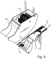
- a holder arrangement 10 is shown which may be similarly configured as the holder arrangement 10 shown in figures 2 and 3 .
- the holder arrangement 10 is attached to a carrier or bin 30, carrying component tape reels 23.
- the holder arrangement 10 is releasably attached to the bin 30 by means of a second locking element 16.
- the bin 30 may comprise a handle 32, or gripping means, for facilitating handling and transport of the bin 30.
- the bin 30 can for example be loaded in a magazine 40 configured to be inserted in a component mounting machine.
- the bin 30, carrying the component tape reels 23 and the holder arrangement 10 with the plurality of feeders 20 has not yet been loaded into the magazine 40.
- Figure 6 illustrates a holder arrangement 10, which may be similarly configured as the embodiments described in connection with the previous figures, when attached to the component magazine 40.
- the tape bin 30, carrying the component tape reels 23, may be accommodated in the magazine 40.
- This magazine 40 may then be loaded into a component mounting machine.
- the component magazine 40 may comprise an electrical means and a drive mechanism 41 for feeding the component tape 22 towards the picking position of the component mounting machine.
- the electrical means may include communicating means adapted to communicate with the component feeders 20 by means of a wired or wireless connection.
- the communication may include retrieving information relating to e.g. component type, component width, tape type or component feeder 20 identity such that the magazine may adapt its configurations to fit the feeder in use.
- a person may first attach the feeders 20 to the holding arrangement 10, then attach the second locking element 16 of the holding arrangement 10 to the tape bin 30 that accommodates the tape reels 23, carry the tape bin 30 to the magazine 40, move the tape bin into the magazine 40, detach the second locking element 16 from the tape bin 30 and attach the first locking element 11 to the magazine 40.
- the magazine 40 may then be loaded into the component mounting machine for mounting the components from the feeders 20.
- a holder arrangement in accordance with the present disclosure allows for an easy handling and quick replenishment of feeders.
- inventive concept has mainly been described with reference to a limited number of examples. However, as is readily appreciated by a person skilled in the art, other examples than the ones disclosed above are equally possible within the scope of the inventive concept, as defined by the appended claims.
Landscapes
- Engineering & Computer Science (AREA)
- Manufacturing & Machinery (AREA)
- Microelectronics & Electronic Packaging (AREA)
- Supply And Installment Of Electrical Components (AREA)
Priority Applications (4)
| Application Number | Priority Date | Filing Date | Title |
|---|---|---|---|
| EP18201892.9A EP3644701A1 (de) | 2018-10-23 | 2018-10-23 | Halterungsanordnung |
| US17/276,347 US11903135B2 (en) | 2018-10-23 | 2019-10-23 | Holder arrangement |
| EP19789995.8A EP3871479A1 (de) | 2018-10-23 | 2019-10-23 | Halterungsanordnung |
| PCT/EP2019/078813 WO2020083968A1 (en) | 2018-10-23 | 2019-10-23 | Holder arrangement |
Applications Claiming Priority (1)
| Application Number | Priority Date | Filing Date | Title |
|---|---|---|---|
| EP18201892.9A EP3644701A1 (de) | 2018-10-23 | 2018-10-23 | Halterungsanordnung |
Publications (1)
| Publication Number | Publication Date |
|---|---|
| EP3644701A1 true EP3644701A1 (de) | 2020-04-29 |
Family
ID=64023953
Family Applications (2)
| Application Number | Title | Priority Date | Filing Date |
|---|---|---|---|
| EP18201892.9A Withdrawn EP3644701A1 (de) | 2018-10-23 | 2018-10-23 | Halterungsanordnung |
| EP19789995.8A Pending EP3871479A1 (de) | 2018-10-23 | 2019-10-23 | Halterungsanordnung |
Family Applications After (1)
| Application Number | Title | Priority Date | Filing Date |
|---|---|---|---|
| EP19789995.8A Pending EP3871479A1 (de) | 2018-10-23 | 2019-10-23 | Halterungsanordnung |
Country Status (3)
| Country | Link |
|---|---|
| US (1) | US11903135B2 (de) |
| EP (2) | EP3644701A1 (de) |
| WO (1) | WO2020083968A1 (de) |
Families Citing this family (1)
| Publication number | Priority date | Publication date | Assignee | Title |
|---|---|---|---|---|
| TWI909646B (zh) * | 2024-08-23 | 2025-12-21 | 技高工業股份有限公司 | 供料器裝卸設備及其供料器 |
Citations (3)
| Publication number | Priority date | Publication date | Assignee | Title |
|---|---|---|---|---|
| EP1298977A1 (de) * | 2001-09-19 | 2003-04-02 | Mydata Automation AB | Verfahren zum Handhaben von Bauteilen an einer Bauteilbestückungsmaschine |
| EP1438884A1 (de) * | 2001-09-07 | 2004-07-21 | Mydata Automation AB | Verfahren, system und anordnung zur behandlung von komponentenbändern |
| US20130161371A1 (en) * | 2010-10-14 | 2013-06-27 | Panasonic Corporation | Tape feeder and method of mounting tape onto tape feeder |
-
2018
- 2018-10-23 EP EP18201892.9A patent/EP3644701A1/de not_active Withdrawn
-
2019
- 2019-10-23 WO PCT/EP2019/078813 patent/WO2020083968A1/en not_active Ceased
- 2019-10-23 EP EP19789995.8A patent/EP3871479A1/de active Pending
- 2019-10-23 US US17/276,347 patent/US11903135B2/en active Active
Patent Citations (3)
| Publication number | Priority date | Publication date | Assignee | Title |
|---|---|---|---|---|
| EP1438884A1 (de) * | 2001-09-07 | 2004-07-21 | Mydata Automation AB | Verfahren, system und anordnung zur behandlung von komponentenbändern |
| EP1298977A1 (de) * | 2001-09-19 | 2003-04-02 | Mydata Automation AB | Verfahren zum Handhaben von Bauteilen an einer Bauteilbestückungsmaschine |
| US20130161371A1 (en) * | 2010-10-14 | 2013-06-27 | Panasonic Corporation | Tape feeder and method of mounting tape onto tape feeder |
Also Published As
| Publication number | Publication date |
|---|---|
| US20220078957A1 (en) | 2022-03-10 |
| US11903135B2 (en) | 2024-02-13 |
| WO2020083968A1 (en) | 2020-04-30 |
| EP3871479A1 (de) | 2021-09-01 |
Similar Documents
| Publication | Publication Date | Title |
|---|---|---|
| KR100646909B1 (ko) | 부품 장착 머신의 테잎 가이드 및 테잎 매거진 | |
| US5562384A (en) | Tape packaging system with removeable covers | |
| JP4237621B2 (ja) | 電子部品テープを取り扱うための方法、システム、および配置 | |
| EP3046403B1 (de) | Substratarbeitssystem, arbeitsverfahren und speiserübertragungsverfahren | |
| US6266873B1 (en) | Method and apparatus for mounting electronic components | |
| US20170339807A1 (en) | Tape feeder and component mounter | |
| EP3307040A1 (de) | Vorrichtung für haltewerkzeug zur komponentenzuführung | |
| US11903135B2 (en) | Holder arrangement | |
| JP6049741B2 (ja) | フィーダ型部品供給装置 | |
| US12439574B2 (en) | Housing device | |
| JP7834833B2 (ja) | フィーダセットアップ装置 | |
| JP7394308B2 (ja) | 部品装着装置 | |
| EP4059329B1 (de) | Bandführung zum führen eines komponentenbandes | |
| JP7829138B1 (ja) | リールラック | |
| WO2023007658A1 (ja) | 部品装着機 | |
| JP7829139B1 (ja) | 作業システム | |
| JP7756344B2 (ja) | テープカセット供給装置、部品搭載システムおよびテープカセット供給方法 | |
| JP7829140B1 (ja) | 作業装置 | |
| JP7174133B2 (ja) | 電子部品装着機 | |
| JPH04300126A (ja) | 組立装置 | |
| JP2024111866A (ja) | テープカセット供給装置、部品装着システム及びテープカセット供給方法 | |
| JP6505888B2 (ja) | 対基板作業システム | |
| US11445648B2 (en) | Feeder | |
| WO2024176431A1 (ja) | フィーダ | |
| JP2019091952A (ja) | 対基板作業システム |
Legal Events
| Date | Code | Title | Description |
|---|---|---|---|
| PUAI | Public reference made under article 153(3) epc to a published international application that has entered the european phase |
Free format text: ORIGINAL CODE: 0009012 |
|
| STAA | Information on the status of an ep patent application or granted ep patent |
Free format text: STATUS: THE APPLICATION HAS BEEN PUBLISHED |
|
| AK | Designated contracting states |
Kind code of ref document: A1 Designated state(s): AL AT BE BG CH CY CZ DE DK EE ES FI FR GB GR HR HU IE IS IT LI LT LU LV MC MK MT NL NO PL PT RO RS SE SI SK SM TR |
|
| AX | Request for extension of the european patent |
Extension state: BA ME |
|
| STAA | Information on the status of an ep patent application or granted ep patent |
Free format text: STATUS: THE APPLICATION IS DEEMED TO BE WITHDRAWN |
|
| 18D | Application deemed to be withdrawn |
Effective date: 20201030 |