EP3644829B1 - Ophthalmologisches gerät - Google Patents
Ophthalmologisches gerät Download PDFInfo
- Publication number
- EP3644829B1 EP3644829B1 EP18730737.6A EP18730737A EP3644829B1 EP 3644829 B1 EP3644829 B1 EP 3644829B1 EP 18730737 A EP18730737 A EP 18730737A EP 3644829 B1 EP3644829 B1 EP 3644829B1
- Authority
- EP
- European Patent Office
- Prior art keywords
- eye
- mask
- light
- subject
- light source
- Prior art date
- Legal status (The legal status is an assumption and is not a legal conclusion. Google has not performed a legal analysis and makes no representation as to the accuracy of the status listed.)
- Active
Links
Images


Classifications
-
- A—HUMAN NECESSITIES
- A61—MEDICAL OR VETERINARY SCIENCE; HYGIENE
- A61B—DIAGNOSIS; SURGERY; IDENTIFICATION
- A61B3/00—Apparatus for testing the eyes; Instruments for examining the eyes
- A61B3/10—Objective types, i.e. instruments for examining the eyes independent of the patients' perceptions or reactions
- A61B3/107—Objective types, i.e. instruments for examining the eyes independent of the patients' perceptions or reactions for determining the shape or measuring the curvature of the cornea
-
- A—HUMAN NECESSITIES
- A61—MEDICAL OR VETERINARY SCIENCE; HYGIENE
- A61B—DIAGNOSIS; SURGERY; IDENTIFICATION
- A61B3/00—Apparatus for testing the eyes; Instruments for examining the eyes
- A61B3/10—Objective types, i.e. instruments for examining the eyes independent of the patients' perceptions or reactions
- A61B3/1005—Objective types, i.e. instruments for examining the eyes independent of the patients' perceptions or reactions for measuring distances inside the eye, e.g. thickness of the cornea
Definitions
- the invention relates to an ophthalmological apparatus for inspecting a patient's eye.
- the invention relates to apparatus which involve projecting a light pattern onto the patient's eye.
- an eye practitioner e.g. ophthalmologist, optometrist or dispensing optician
- a slit lamp biomicroscope also known as a slit lamp
- the slit lamp enables the eye care practitioner to obtain a magnified view of various structures near the surface of the human eye, such as the eyelid, cornea, conjunctiva, sclera, iris and lens.
- the slit lamp is therefore a useful tool for diagnosing a wide variety of eye conditions, and it is currently one of the most widely used tools in the field of eye care.
- a slit lamp works by producing a beam of light which can be adjustably moved and focused to image relevant portions of a patient's eye.
- the beam is produced by shining light from a light source through an aperture.
- the beam is then focused onto the patient's eye to illuminate a portion of the patient's eye.
- the aperture used is usually slit-shaped, such that the illuminated portion of the eye is slit-shaped.
- the eye is viewed through an optical line-up (e.g. similar to a microscope) that provides a magnified view of the illuminated portion of the eye.
- the slit lamp may also include a camera connected to record the magnified images of the patient's eye.
- a conventional slit lamp instrument thus includes three main components: an illumination system, an observation system and a mechanical system which couples the illumination system to the observation system.
- the illumination system includes a light source (e.g. a lamp) which produces light, a mechanical aperture (e.g. a slit) through which the light is shone in order to produce a light beam, filters (e.g. for amplifying light sensitive stains) and a series of optical components for focusing and positioning the light beam.
- the light beam can be projected onto a patient's eye to produce an image of the aperture on the patient's eye, thus illuminating a portion of the patient's eye.
- the portion of the eye which is illuminated, as well as the shape of the illuminated portion can be adjusted by manually adjusting the shape and position of the mechanical aperture.
- a moveable shutter on the mechanical aperture can be used to vary the size of the aperture.
- the light source emits optical radiation, usually in the visible spectrum, and may for example be a broadband light source.
- the colour of the light can be modified by placing a colour filter in front of the light beam.
- the observation system includes a microscope having an objective lens and an eyepiece arranged to give an operator a magnified view of the patient's eye (typically up to 40x).
- the microscope is often a binocular microscope, in order to provide the operator with a stereoscopic view.
- the microscope can include multiple interchangeable objective lenses for switching between different levels of magnification.
- a camera port can be included so that a camera may be connected to the microscope in order to record images of the patient's eye for analysis.
- the mechanical system couples the illumination system to the observation system.
- the mechanical system permits relative movement between the illumination and observation systems with respect to a base to which they are both connected.
- the mechanical system includes a three-axis positioning stage for accurately positioning the beam in relation to the patient's eye.
- the stage position is controlled manually using a set of knobs or a joystick.
- the observation and illumination systems are coupled so that they are rotatable relative to the base about a common axis of rotation.
- the mechanical system also includes a head rest to position the patient's face relative to the instrument. This will typically include a chin rest and a band against which the patient may place their forehead, both of which are vertically adjustable. Additionally, the mechanical system often includes a movable fixation target, on which an operator can ask the patient to focus during the examination procedure.
- a conventional slit lamp is therefore a complex device including many moving parts which require significant manual adjustment and fine tuning in order to successfully carry out an examination of the patient's eye.
- a slit lamp operator must adjust the head rest and fixation target in order to appropriately position the patient's eye relative to the instrument. The operator must then use the three-axis positioning stage to focus the light beam on the desired portion of the patient's eye. Finally, the microscope must be adjusted so that its focal plane coincides with the focal plane of the aperture image projected onto the patient's eye. If multiple portions of the patient's eye are to be examined, these adjustments may need to be repeated several times, which can lead to a time consuming examination procedure. If different filters or aperture sizes are to be used, this also requires a manual adjustment of the slit lamp.
- the curvature of the eye's surface causes a light pattern reflected by the eye's surface to be distorted.
- Different angles of incidence of the light beam relative to the eye's surface can lead to different levels of distortion. It can therefore be desirable to maintain a constant angle of incidence across a series of measurements, to ensure that the level of distortion remains constant.
- This facilitates data analysis procedures which involve the comparison of multiple measurements (e.g. using recorded images of the reflected patterns).
- an operator of the slit lamp may wish to adjust the slit lamp such that the angle of incidence between the light beam and the eye's surface is as close as possible to 90 degrees. This can be difficult to achieve in practice however, as conventional slit lamps do not include a mechanism for measuring the angle of incidence relative to the curved cornea. The operator will therefore have to rely on his own judgement and ability to adjust the slit lamp in order to maintain a constant angle of incidence.
- Prior art document US 6,447,119 discloses an ophthalmological apparatus for inspecting an eye and a method of viewing the surface of a subject's eye according to the preambles of claims 1 and 13 respectively.
- Prior art document US 2017/042421 discloses a modular unit for use as part of an ophthalmological apparatus according to the preamble of claim 11.
- the present invention provides an ophthalmological apparatus with a digitally controllable mask for facilitating rapid and repeatable eye inspection.
- the digitally controllable mask may be a mask that is controlled by electronic signals to set and adjust the extent to which it blocks or transmits light from a light source.
- the apparatus may further comprise a light source and imaging device that are operable with the mask in a complementary fashion to aid efficient eye inspection.
- an ophthalmological apparatus for inspecting an eye
- the apparatus comprising: a light source; a mask arranged to selectively block transmission of light from the light source to form a mask pattern that is projectable onto a subject's eye, wherein the mask is adjustable based on a digital control signal to alter the mask pattern; and an imaging device for viewing the mask pattern on the subject's eye.
- the digital control signal may be provided by a suitable controller, e.g. computer, tablet, smartphone or other suitable processing apparatus, to enable the mask pattern projected onto the eye to be controlled in an automated or quasi-automated manner.
- the present invention does not require manual adjustment of moving parts to control the shape and position of the projected pattern, thus making the apparatus of the invention much simpler to operate.
- An advantage of the ophthalmological apparatus of the invention is that the observation procedure can be fully automated such that it requires minimal user intervention. Using the ophthalmological apparatus, images of the subject's eye can be recorded and analysed in order to determine various properties of the subject's eye.
- the mask may selectively block transmission of light from the light source by having light-transmitting region(s) and regions which are opaque or cause reduced light transmission.
- the mask pattern may be formed by a light-transmitting region in the shape of a slit, a ring, a series of concentric rings or any other complex two-dimensional pattern.
- the mask pattern may be time-varying. For example, in the case of a pattern including a light-transmitting slit, the slit can be swept from one side of the mask to another side of the mask.
- the light transmission properties of the mask pattern may be wavelength-dependent, such that certain portions (or all) of the mask pattern may filter out particular wavelengths from the transmitted light, or tune the transmitted light to a particular wavelength.
- the mask may further be capable of displaying a fixation target for the patient to focus on during the measurement procedure.
- the fixation target may be movable, in order to cause the patient to move their eyes in a desired way during the measurement.
- the digital control signal is used.
- the position of the fixation target may also be based on the digital control signal.
- the digital control signal may be generated by a controller/processor which is integrated in the apparatus or which is in a separate device. Adjusting the mask pattern refers, for example, to varying parameters such as the shape, size, position, and/or colour of the light-transmitting region of the mask pattern. Therefore no three-axis stage or mechanical apertures are required to adjust the mask pattern, as is the case for a conventional slit lamp. This can greatly facilitate operation of the device.
- the light source may be a conventional light source such as a projector lamp or a light panel.
- the light source is positioned such that light emitted from the light source can be transmitted through the mask and impinge on a subject which is on the opposite side of the mask to the light source. This enables the mask pattern to be projected onto the subject. By adjusting the mask pattern, the shape, size, position and/or colour of the mask pattern projected onto the subject's eye can be varied.
- the apparatus may include optical components before or after the mask to control the direction or beam shape of the emitted light.
- the apparatus may include a collimator or similar, which can enable sharper images of the mask pattern to be obtained.
- the imaging device serves to view the mask pattern on the subject's eye.
- the imaging device is arranged such that light reflected from the subject's eye forms an image at the imaging device which is viewable by a user.
- the imaging device can include any combination of conventional apparatus used for producing an image from incident light, such as an objective lens, a microscope, an image sensor or a camera.
- the imaging device may have an adjustable zoom and focus, for viewing features at different depths in the eye's surface and at different levels of magnification.
- the imaging device may also be configured to record images of the mask pattern on the subject's eye and store the images in a memory.
- the position of the imaging device may be adjusted with respect to the light source and mask in order to improve depth perception. More than one imaging device might be included, for example to enable 3-dimentional image reconstruction.
- the apparatus may further include a face rest (e.g. chin rest and/or forehead rest) for positioning a patient's face relative to the apparatus. This ensures that the subject's face is held in place during the course of a measurement.
- the face rest may include a positioning stage (e.g. a three-axis stage) for setting the position of the patient's face relative to the apparatus at the beginning of a measurement.
- the mask may comprise an array of independently controllable masking elements, each masking element being adjustable, e.g. based on the digital control signal, between a transmissive state for transmitting light from the light source and an opaque state for blocking transmission of light from the light source.
- the state of each masking element therefore determines the amount (i.e. intensity) of light from the light source which it can transmit.
- the state of the masking element may also determine the colour of the light transmitted.
- the mask pattern is adjusted by adjusting the state of one or more masking elements.
- Each independently controllable masking element may be independently addressable, i.e. associated with a respective address (e.g. digital label) in order for it to be controlled individually via the digital control signal.
- the digital control signal may contain a series of masking element addresses and a series of state indicators, where each masking element address is associated with a respective state indicator.
- a state indicator indicates the state to which a masking element should be adjusted.
- the state of each masking element is adjusted in accordance with the state indicator which is associated with that masking element's address in the digital control signal. If the masking element addresses included in the digital control signal represent a subset of the masking elements in the mask, then only the states of the masking elements corresponding to the addresses included in the digital control signal are adjusted.
- the array may be mounted in a frame for locating in an optical path from the light source to the subject's eye.
- the mask may comprise a liquid crystal display (LCD) window, i.e. an LCD screen mounted within a frame, where the masking elements correspond to the LCD screen's pixels.
- the light source may also be controllable.
- the light source comprises a light-emitting portion from which light is projected out of the apparatus, and wherein a relative position of the light-emitting portion and the mask is controllable to permit adjustment of an angle of incidence of the mask pattern projectable onto the subject's eye. In other words, when light from the light source is projected through the mask, it may form a light beam corresponding to the mask pattern.
- the light-emitting portion of the light source may refer to a region (e.g. a subregion) on the light source from which light can be emitted.
- the angle of incidence is defined as the angle between a beam incident on the subject's eye and the normal to the eye's surface at the point of incidence of the light beam on the eye's surface.
- the light source may include an array of selectively activatable lighting elements.
- the relative position of the light-emitting portion and the mask may be controllable by selectively activating one or more of the lighting elements.
- the array of selectively activatable lighting elements may be a panel array of LEDs or light bulbs. Activating one or more of the lighting elements may refer to causing the one or more lighting elements to emit light.
- the light-emitting portion can therefore be defined by the lighting elements which are activated.
- a single lighting element may be activated, in which case the light-emitting portion of the light source can be defined as the position of the activated lighting element.
- multiple lighting elements are activated (e.g.
- the light-emitting portion of the light source can be defined as an average position of the activated lighting elements. Different lighting elements can be activated sequentially, in order to move the light-emitting portion of the light source and adjust the angle of incidence of the mask pattern projected onto the subject's eye.
- the light source may include a lighting element and a secondary mask arranged to selectively block transmission of light from the lighting element.
- the relative position of the light-emitting portion and the mask may be controllable by adjusting a position of a light-transmitting region of the secondary mask relative to the lighting element.
- the lighting element may serve to emit light, and may for example be a projector lamp or a light panel (such as an LED or OLED panel).
- the secondary mask may be arranged such that it is on a light path between the lighting element and the digitally controllable mask discussed above (referred to as the first mask below). Light from the light source which reaches the first mask will have passed through the secondary mask.
- the light-emitting portion of the light source can be defined by the position of the light-transmitting region (e.g. as a point in the light-transmitting region).
- the secondary mask may also be digitally controllable, e.g. based on a second digital control signal.
- the secondary mask may have any of the features discussed herein with respect to the first mask.
- the secondary mask may comprise an array of independently controllable masking elements analogous to those discussed above in relation to the first mask.
- the second digital control signal may indicate a shape, size and position of the light-transmitting region on the secondary mask.
- the light source may be provided by lighting elements in the display of a tablet computer or smartphone.
- the tablet computer or smartphone may be removably attachable to the mask, e.g. via a supporting frame or the like.
- the tablet computer or smartphone may include software enabling it to produce light at a desired position on its screen and of a desired colour.
- the tablet computer or smartphone may be controlled remotely when it is installed in the ophthalmological apparatus (e.g. wirelessly or through a communication port), or a lighting sequence may be pre-programmed before it is installed in the apparatus.
- the tablet computer or smartphone may be configured to control the mask, such that an entire measurement routine may be run by software on the tablet computer or smartphone, and any required image analysis may be performed by a processor therein.
- a tablet computer or smartphone as a light source in the ophthalmological apparatus provides a convenient and easily transportable solution, as no additional computer may be required to operate the apparatus.
- the apparatus may comprise a polariser arranged to polarise light from the light source.
- the polariser may be provided in the mask or in the light source or in both the mask and the light source.
- the polariser may serve to reduce glare back into the imaging device or to allow investigation of the reflection of light from structures in the patient's eye.
- the polariser may also serve to increase colour saturation.
- the imaging device may include: an image sensor for capturing a digital image, an optical line-up arranged to focus an image of the mask pattern that is formed on the subject's eye onto the image sensor, and a display for displaying the captured digital image.
- the optical line-up may comprise one or more optical elements (e.g. lenses or the like), e.g. an objective lens.
- the image sensor may for example be a CCD chip or other suitable image sensing device.
- the image sensor may be connected to the display such that images detected by the image sensor are shown on the display.
- the optical line-up may have an adjustable zoom and focus.
- the image sensor may comprise a pair of independent image sensors disposed in a spaced relationship to enable stereoscopic images to be detected. This allows a three-dimensional image of the patient's eye to be reconstructed. In addition to allowing stereoscopic images to be detected, such a configuration may also enable the surfaces of both of a subject's eyes to be viewed simultaneously.
- the stereoscopic depth of the images can be enhanced by increasing the separation between the image sensors. For example, the stereoscopic depth of the images can be enhanced by separating the image sensors by more than the separation of human eyes, which is typically around 60 mm.
- the imaging device may include a camera arranged to record an image of the mask pattern on the subject's eye.
- An objective lens may be used to focus light onto an image sensor of the camera.
- the imaging device may also include two cameras to allow stereoscopic images to be captured.
- a stereoscopic image of the entire eye can be obtained by capturing images of different portions of the eye and stitching the images together.
- a user may pan around and zoom into areas of interest to analyse a feature of the anterior eye (e.g. a scratch). Properties such as the depth and profile of the feature may be determined from the stereoscopic image.
- the imaging device may be disposed behind the mask relative to the direction in which the mask pattern is emitted therethrough.
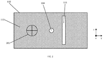
- the mask may include an aperture to permit the imaging device to view the mask pattern on the subject's eye.
- the aperture may be an actual hole in the mask, or it may be a light-transmitting region of the mask through which the imaging device can see. Where the aperture is a light-transmitting region of the mask, the size and position of the aperture may be varied, based on the digital control signal, in accordance with the requirements of a particular measurement.
- the aperture allows the imaging device to be located on an opposite side of the mask to the subject.
- the mask may include two separate apertures so that each image sensor/camera can receive light reflected from the subject's eye.
- the apparatus may comprise a pair of flat panels that are disposed substantially parallel to each other, whereby the apparatus takes the form of a cuboidal, which may be the size of a book.
- the mask may be contained within a first panel and the light source may be contained within a second panel.
- the two panels may have similar dimensions.
- the panels may be spaced by a distance which optimizes the range of angles through which the mask pattern can be swept across the subject's eye.
- the imaging device can be located between the light source and the mask, e.g. within the cuboidal body formed by the panels.
- the imaging device may be located behind the light source, such that the light source is located between the imaging device and the mask. In this case, an additional aperture in the light source may be necessary for the imaging device to see the subject's eye through.
- the apparatus may include a controller configured to generate the digital control signal.
- the controller can for example generate the digital control signal based on a user input, or based on a pre-programmed measurement routine.
- the controller can further transmit the digital control signal to the mask, so that the mask may adjust the mask pattern based on the digital control signal.
- the controller may be integrated in the ophthalmological apparatus, or it may be included in an external control device. In the case where the controller is part of an external control device, the control device may be configured to communicate with the ophthalmological apparatus, for example wirelessly or via a cable.
- the controller and/or control device may include software which allows a user to set the mask pattern that is to be projected onto the subject's eye.
- the controller and/or control device may also enable the user to control the position of the fixation target.
- the controller/control device includes a touchscreen, such that the mask pattern may be adjusted via finger gestures on the touchscreen.
- the controller may further be configured to generate the second digital control signal for controlling the light-emitting portion of the light source.
- the software may then enable the user to set the light-emitting portion of the light source and/or the colour of light emitted by the light source.
- a user may thus simultaneously control the light-emitting portion of the light source and the mask pattern, in order to project the mask pattern onto a relevant portion of the subject's eye and sweep the mask pattern across the subject's eye.
- the controller may also be configured to receive data (e.g. recorded images) from the imaging device and set one or more image capture parameters of the imaging device (e.g. zoom, focus, exposure time, filters). Recorded images can be analysed by the controller or a separate computing device to determine properties of the patient's eye such as corneal topography or tear film stability.
- the controller/control device may include a memory module in which pre-programmed measurement routines are stored.
- the pre-programmed measurement routines may define sequences of mask patterns, light-emitting portions of the light source, and image capture parameters of the imaging device.
- the user can select a measurement routine, which causes the controller to generate a sequence of control signals for controlling the mask pattern, light source and imaging device according to the pre-programmed routine.
- the controller may be configured to, in response to an analysis performed on a recorded image, control one or more of the mask, light source and imaging device to adjust a measurement parameter (e.g. by generating and transmitting corresponding control signals).
- the measurement parameters can include, but are not limited to: light-emitting portion of the light source; shape, size and position of the mask pattern; zoom, focus and exposure time of the imaging device.
- the controller thus allows for centralised control of all the components of the ophthalmological apparatus, thus enabling automatic operation of the apparatus. This avoids much of the difficulty associated with operating conventional slit lamps.
- a modular unit for use as part of an ophthalmological apparatus comprising: a frame for locating adjacent a subject's eye, the frame comprising: a mask mounted thereon; a first mounting portion arranged to receive a light source on the opposite side of the mask from the subject's eye; a second mounting portion arranged to receiving an imaging device, wherein the mask is arranged to selectively block transmission of light from the light source to form a mask pattern that is projectable onto a subject's eye, wherein the mask is adjustable based on a digital control signal to permit adjustment of the mask pattern, and wherein the second mounting portion is arranged to locate the imaging device in a position to view the mask pattern on the subject's eye.
- the ophthalmological apparatus of which the modular unit is used as a part, is based on the same principles as the ophthalmological apparatus discussed above. Accordingly, features of the first aspect of the invention above may be shared by the second aspect of the invention and are not discussed again.
- An advantage of such a modular unit is that it can be used with a variety of light sources and imaging devices, such that the ophthalmological apparatus can be optimally configured to suit particular measurement requirements. Furthermore, this facilitates transport of the ophthalmological apparatus, as the components can be removed from the modular unit, thus making the modular unit compact and easily transportable.
- the frame may be any suitable means for connecting the mask, light source and imaging device together.
- it may consist of an enclosure having slots in which the various components may be installed.
- the components may be removably attachable to the frame using suitable fastening means, such as, but not limited to, screws, clamps, clips and/or magnets. This enables components to be quickly and easily installed in, and removed from, the frame.
- the frame may also include a face rest for positioning the patient's face relative to the modular unit.
- the frame may be foldable.
- the mask is removably attached to the frame. This further increases the flexibility and transportability of the modular unit.
- a tablet computer or smartphone is removably attachable to the frame such that, when the tablet computer or smartphone is attached to the frame, lighting elements in the display of the tablet computer or smartphone provide the light source.
- a method of viewing the surface of a subject's eye including: positioning a mask between the subject's eye and a light source; transmitting a digital control signal to the mask to selectively block transmission of light from the light source and thereby project a mask pattern onto the subject's eye; and viewing, by an imaging device, the mask pattern on the subject's eye.
- This method may be partially or entirely carried out by a controller which is configured to control one or more of the mask, light source and imaging device, thus simplifying the procedure compared to that used with conventional slit lamps.
- the controller may be configured to generate the digital control signal and transmit it to the mask (e.g. wirelessly or via a cable).
- This method may be used to operate the ophthalmological apparatus according to the first aspect of the invention.
- the features of the first aspect of the invention may therefore be shared with this aspect of the invention, and are not discussed again.
- the light source comprises a light-emitting portion from which light is projected.
- the method includes controlling a relative position of the light-emitting portion and the mask to select or adjust an angle of incidence of the mask pattern projected onto the subject's eye.
- the method may include moving the mask pattern across the subject's eye, and controlling the angle of incidence of the mask pattern as it is moved over the subject's eye so that it is substantially normal to a surface of the eye.
- the method may include recording, by the imaging device, an image of the mask pattern on the subject's eye; analysing the recorded image; and based on the analysis of the recorded image, controlling one or more of the mask, light source and imaging device to adjust a measurement parameter.
- the imaging device may record the image in a memory which is accessible by the controller.
- Measurement parameters can include, but are not limited to: a location of the light-emitting portion of the light source; shape, size and position of the mask pattern; zoom, focus and exposure time of the imaging device. This enables the measurement parameters to be automatically updated in real time, and so can allow for faster measurements.
- the light-emitting portion of the light source and the position of the mask pattern on the mask can be adjusted until the desired angle is obtained.
- the method may include projecting a mask pattern of known dimensions onto the subject's eye, the subject's eye being located at a known distance from the imaging device; recording, using the imaging device, an image of the mask pattern on the subject's eye; and analysing the recorded image, in order to calculate the shape of the subject's eye.
- the shape of the subject's eye can be calculated by comparing the distortions of the mask pattern formed on the patient's eye to the known dimensions of the projected mask pattern. This can provide a high resolution three-dimensional reconstruction of the surface of the patient's eye.
- the calculated shape of the subject's eye can be used, for example, when performing measurements such as tear film stability or corneal thickness/depth analysis, in order to improve the accuracy of the measurement.
- the method may include recording, by the imaging device, a series of images of the mask pattern on the subject's eye; and analysing the series of recorded images in order to determine tear film stability and/or lipid layer thickness in the subject's eye.
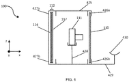
- the face rest 430 may include a chin rest on which the patient may place their chin, a head rest (not shown) against which the patient may place their forehead and/or other components suitable for holding and positioning the patient's face relative to the ophthalmological apparatus 100.
- the frame 425 may form an enclosure such that only the front face of the primary mask 110 is exposed, in order to prevent light from leaking in during the measurement.
- the frame 425 is shown for illustrative purposes only, and many other alternative frame configurations are possible.
Landscapes
- Life Sciences & Earth Sciences (AREA)
- Health & Medical Sciences (AREA)
- Medical Informatics (AREA)
- Biophysics (AREA)
- Ophthalmology & Optometry (AREA)
- Engineering & Computer Science (AREA)
- Biomedical Technology (AREA)
- Heart & Thoracic Surgery (AREA)
- Physics & Mathematics (AREA)
- Molecular Biology (AREA)
- Surgery (AREA)
- Animal Behavior & Ethology (AREA)
- General Health & Medical Sciences (AREA)
- Public Health (AREA)
- Veterinary Medicine (AREA)
- Eye Examination Apparatus (AREA)
Claims (15)
- Ophthalmologische Vorrichtung (100) zum Untersuchen eines Auges, wobei die Vorrichtung Folgendes umfasst:eine Lichtquelle (112);eine Maske (110), die ausgebildet ist, um die Transmission von Licht von der Lichtquelle (112) selektiv zu blockieren, um ein Maskenmuster zu bilden, das auf das Auge (121) eines Individuums projizierbar ist, wobei die Maske (110) basierend auf einem digitalen Steuersignal einstellbar ist, um das Maskenmuster zu ändern; undeine Bildgebungsvorrichtung (111) zum Betrachten des Maskenmusters auf dem Auge des Individuums,dadurch gekennzeichnet, dassdie Lichtquelle (112) einen lichtemittierenden Abschnitt umfasst, von dem aus Licht aus der Vorrichtung hinaus projiziert wird, und wobei eine relative Position des lichtemittierenden Abschnitts und der Maske (110) steuerbar ist, um das Einstellen eines Einfallswinkels des Maskenmusters, das auf das Auge (121) des Individuums projizierbar ist, zu erlauben.
- Ophthalmologische Vorrichtung (100) nach Anspruch 1, wobei die Maske (110) eine Anordnung von unabhängig steuerbaren maskierenden Elementen umfasst, wobei jedes maskierende Element basierend auf dem digitalen Steuersignal zwischen einem Transmissionszustand für die Transmission von Licht von der Lichtquelle (112) und einem nichtdurchlässigen Zustand für das Blockieren der Transmission von Licht von der Lichtquelle (112) einstellbar ist und gegebenenfalls:wobei die Anordnung zum Anordnen in einem optischen Pfad von der Lichtquelle (112) zu dem Auge (121) des Individuums in einem Rahmen (425) angebracht ist, und/oderwobei jedes unabhängig steuerbare maskierende Element unabhängig adressierbar ist.
- Ophthalmologische Vorrichtung (100) nach Anspruch 1 oder Anspruch 2, wobei die Maske ein Flüssigkristall-Anzeigefenster umfasst.
- Ophthalmologische Vorrichtung (100) nach Anspruch 1, wobei die Lichtquelle (112) eine Anordnung selektiv aktivierbarer Beleuchtungselemente umfasst und wobei die relative Position des lichtemittierenden Abschnitts und der Maske (110) durch selektives Aktivieren eines oder mehrerer der Beleuchtungselemente steuerbar ist; oder
wobei die Lichtquelle (112) ein Beleuchtungselement (116) und eine sekundäre Maske (117) umfasst, die ausgebildet ist, um die Transmission von Licht von dem Beleuchtungselement (116) selektiv zu blockieren und wobei die relative Position des lichtemittierenden Abschnitts und der Maske (110) durch Einstellen einer Position eines lichttransmittierenden Bereichs der sekundären Maske (117) relativ zu dem Beleuchtungselement steuerbar ist und wobei die sekundäre Maske (117) gegebenenfalls basierend auf einem zweiten digitalen Steuersignal steuerbar ist. - Ophthalmologische Vorrichtung (100) nach einem der vorangegangenen Ansprüche, wobei die Lichtquelle (112) durch Beleuchtungselemente in der Anzeige eines Tabletcomputers oder einem Smartphone bereitgestellt ist.
- Ophthalmologische Vorrichtung (100) nach einem der vorangegangenen Ansprüche, die einen Polarisator umfasst, der ausgebildet ist, um Licht von der Lichtquelle (112) zu polarisieren und
der Polarisator gegebenenfalls in der Maske (110) und/oder der Lichtquelle (112) bereitgestellt ist. - Ophthalmologische Vorrichtung (100) nach einem der vorangegangenen Ansprüche, wobei die Bildgebungsvorrichtung (111) Folgendes umfasst:einen Bildsensor zum Aufnehmen eines digitalen Bilds,eine optische Anordnung, die ausgebildet ist, um ein Bild des Maskenmusters, das auf dem Auge des Individuums auf dem Bildsensor ausgebildet ist, zu fokussieren undeine Anzeige zum Anzeigen des aufgenommenen digitalen Bildes undgegebenenfalls der Bildsensor ein Paar von unabhängigen Bildsensoren umfasst, die in einer beabstandeten Beziehung angeordnet sind, damit sie stereoskopische Bilder detektieren können.
- Ophthalmologische Vorrichtung (100) nach einem der vorangegangenen Ansprüche, wobei die Bildgebungsvorrichtung (111) eine Kamera umfasst, die ausgebildet ist, um ein Bild des Maskenmusters auf dem Auge des Individuums aufzunehmen, und/oder
wobei die Bildgebungsvorrichtung (111) hinter der Maske (110) relativ zu der Richtung, in der das Maskenmuster durch diese hindurch emittiert wird, angeordnet ist und wobei die Maske eine Öffnung umfasst, um der Bildgebungsvorrichtung zu ermöglichen, das Maskenmuster auf dem Auge (121) des Individuums zu betrachten. - Ophthalmologische Vorrichtung (100) nach einem der vorangegangenen Ansprüche, wobei die Maske (110) innerhalb einer ersten Platte enthalten ist und die Lichtquelle (112) innerhalb einer zweiten Platte angeordnet ist, wobei die zwei Platten so ausgebildet sind, dass sie im Wesentlichen parallel sind.
- Ophthalmologische Vorrichtung (100) nach einem der vorangegangenen Ansprüche, die ferner eine Steuerung umfasst, die ausgelegt ist, um ein digitales Steuersignal zu erzeugen,
wobei die Steuerung gegebenenfalls einen Prozessor und Speichersoftwareanweisungen umfasst, wobei die Softwareanweisungen, wenn sie durch den Prozessor ausgeführt werden, so ausgebildet sind, dass sie den Betrieb der Vorrichtung steuern, und/oder die Steuerung mit der Bildgebungsvorrichtung (111) wirkverbunden ist, um das Aufnehmen eines Bilds des Maskenmusterns zu steuern. - Modulare Einheit zur Verwendung als Teil einer ophthalmologischen Vorrichtung (100), wobei die modulare Einheit Folgendes umfasst:
einen Rahmen (425) zum Anordnen benachbart zu einem Auge (121) eines Individuums, wobei der Rahmen (425) Folgendes umfasst:eine Maske (110), die auf diesem angebracht ist;einen ersten Anbringungsabschnitt (427a, 427b), der ausgebildet ist, um eine Lichtquelle (112) aufzunehmen, wobei die Lichtquelle (112) einen lichtemittierenden Abschnitt umfasst, von dem aus auf der entgegengesetzten Seite der Maske (100) von dem Auge (121) des Individuums Licht projiziert wird,einen zweiten Anbringungsabschnitt (428), der ausgebildet ist, um eine Bildgebungsvorrichtung (111) aufzunehmen, wobei der zweite Anbringungsabschnitt (428) ausgebildet ist, um die Bildgebungsvorrichtung (111) in einer Position, in der das Maskenmuster auf dem Auge (121) des Individuums betrachtet werden kann, anzuordnen,wobei, wenn die Lichtquelle in dem ersten Anbringungsabschnitt angebracht ist, die Maske (110) ausgebildet ist, um die Transmission von Licht von der Lichtquelle (112) selektiv zu blockieren, um ein Maskenmuster zu bilden, das auf das Auge (121) eines Individuums projizierbar ist,dadurch gekennzeichnet, dassdie Maske (110) basierend auf einem digitalen Steuersignal einstellbar ist, um das Einstellen des Maskenmusters zu erlauben und wobei eine relative Position des lichtemittierenden Abschnitts und der Maske steuerbar ist, um das Einstellen eines Einfallswinkels des Maskenmusters, das auf das Auge des Individuums projizierbar ist, zu erlauben. - Modulare Einheit nach Anspruch 11, wobei die Maske (110) entfernbar mit dem Rahmen verbunden ist und/oder
wobei der zweite Anbringungsabschnitt (428) so angeordnet ist, dass er einen Tabletcomputer oder ein Smartphone aufnehmen kann, wobei der Tabletcomputer oder das Smartphone die Lichtquelle und/oder die Bildgebungsvorrichtung bereitstellt. - Verfahren zum Betrachten der Oberfläche des Auges (121) eines Individuums, wobei das Verfahren Folgendes umfasst:das Positionieren einer Maske (110) zwischen dem Auge (121) des Individuums und einer Lichtquelle (112);das Übertragen eines digitalen Steuersignals an die Maske (110), um die Transmission von Licht von der Lichtquelle selektiv zu blockieren und dadurch ein Maskenmuster auf das Auge (121) des Individuums zu projizieren; unddas Betrachten des Maskenmusters auf dem Auge (121) des Individuums durch eine Bildgebungsvorrichtung (111),dadurch gekennzeichnet, dassdie Lichtquelle (112) einen lichtemittierenden Abschnitt aufweist, von dem aus Licht projiziert wird, und wobei das Verfahren das Steuern einer relativen Position des lichtemittierenden Abschnitts und der Maske (110) umfasst, um einen Einfallswinkel des auf das Auge (121) des Individuums projizierten Maskenmusters auszuwählen oder einzustellen.
- Verfahren nach Anspruch 13, das Folgendes umfasst:das Bewegen des Maskenmusters über das Auge (112) des Individuums, unddas Steuern des Einfallswinkels des Maskenmusters, während es über das Auge des Individuums bewegt wird, so dass es im Wesentlichen zu einer Oberfläche des Auges normal steht; und/oderdas Aufnehmen eines Bildes des Maskenmusters auf dem Auge (121) des Individuums durch die Bildgebungsvorrichtung;das Analysieren des aufgenommenen Bildes; und,basierend auf der Analyse des aufgenommenen Bildes, das Steuern eines oder mehrerer der Maske (110), der Lichtquelle (112) und der Bildgebungsvorrichtung (111), um einen Messparameter einzustellen.
- Verfahren nach Anspruch 13 oder Anspruch 14, das ferner Folgendes umfasst:das Projizieren eines Maskenmusters mit bekannten Dimensionen auf das Auge (121) des Individuums, wobei sich das Auge (121) des Individuums in einem bekannten Abstand von der Bildgebungsvorrichtung (111) entfernt befindet;das Aufnehmen eines Bildes des Maskenmusters auf dem Auge (121) des Individuums unter Verwendung der Bildgebungsvorrichtung (111) unddas Analysieren des aufgenommenen Bildes, um die Form des Auges (121) des Individuums zu berechnen, und gegebenenfalls ferner Folgendes umfasst:das Steuern der Maske (110) und der Lichtquelle (112), um das Lichtmuster über dem Auge (121) des Individuums abzutasten,wobei die berechnete Form des Auges (121) des Individuums als Eingangsparameter zum Steuern des Abtastens verwendet wird, so dass ein Einfallswinkel des Maskenmusters des Auges (121) des Patienten während des gesamten Abtastvorgangs konstant gehalten wird; und/oderdas Aufnehmen als Bilderserie des Maskenmusters auf dem Auge (121) des Individuums durch die Bildgebungsvorrichtung (111) unddas Analysieren der Serie aufgenommener Bilder, um eine Tränenfilmstabilität und/oder Lipidschichtdicke in dem Auge (121) des Individuums zu bestimmen.
Applications Claiming Priority (2)
| Application Number | Priority Date | Filing Date | Title |
|---|---|---|---|
| GBGB1710461.3A GB201710461D0 (en) | 2017-06-29 | 2017-06-29 | Ophthalmological apparatus |
| PCT/EP2018/065158 WO2019001928A1 (en) | 2017-06-29 | 2018-06-08 | OPHTHALMOLOGICAL APPARATUS |
Publications (2)
| Publication Number | Publication Date |
|---|---|
| EP3644829A1 EP3644829A1 (de) | 2020-05-06 |
| EP3644829B1 true EP3644829B1 (de) | 2021-07-28 |
Family
ID=59592369
Family Applications (1)
| Application Number | Title | Priority Date | Filing Date |
|---|---|---|---|
| EP18730737.6A Active EP3644829B1 (de) | 2017-06-29 | 2018-06-08 | Ophthalmologisches gerät |
Country Status (3)
| Country | Link |
|---|---|
| EP (1) | EP3644829B1 (de) |
| GB (1) | GB201710461D0 (de) |
| WO (1) | WO2019001928A1 (de) |
Families Citing this family (2)
| Publication number | Priority date | Publication date | Assignee | Title |
|---|---|---|---|---|
| CN116940276A (zh) * | 2020-07-09 | 2023-10-24 | 安斯利有限公司 | 测量角膜地形图的设备、系统和方法 |
| EP4178417A4 (de) * | 2020-07-09 | 2024-08-07 | Ainsly Limited | Vorrichtungen, systeme und verfahren zur messung der hornhauttopografie |
Family Cites Families (4)
| Publication number | Priority date | Publication date | Assignee | Title |
|---|---|---|---|---|
| US6447119B1 (en) * | 1996-08-12 | 2002-09-10 | Visionrx, Inc. | Apparatus for visualizing the eye's tear film |
| US9545200B2 (en) * | 2013-11-08 | 2017-01-17 | Precision Ocular Metrology, L.L.C. | Systems and methods for mapping the ocular surface |
| US9615739B2 (en) * | 2014-07-01 | 2017-04-11 | Amo Wavefront Sciences, Llc | System and method for corneal topography with flat panel display |
| US9839352B2 (en) * | 2015-08-15 | 2017-12-12 | Smart EyeDeas I, LLC | System, method and apparatus for enabling corneal topography mapping by smartphone |
-
2017
- 2017-06-29 GB GBGB1710461.3A patent/GB201710461D0/en not_active Ceased
-
2018
- 2018-06-08 WO PCT/EP2018/065158 patent/WO2019001928A1/en not_active Ceased
- 2018-06-08 EP EP18730737.6A patent/EP3644829B1/de active Active
Also Published As
| Publication number | Publication date |
|---|---|
| WO2019001928A1 (en) | 2019-01-03 |
| GB201710461D0 (en) | 2017-08-16 |
| EP3644829A1 (de) | 2020-05-06 |
Similar Documents
| Publication | Publication Date | Title |
|---|---|---|
| US10226174B2 (en) | Ocular fundus imaging systems, devices and methods | |
| TWI851916B (zh) | 疊合虛擬影像於即時影像的系統與方法 | |
| US20190269323A1 (en) | Ocular Fundus Imaging Systems Devices and Methods | |
| EP2679148B1 (de) | Fundusfotografievorrichtung | |
| JP2008212308A (ja) | 眼底カメラ | |
| US20220338733A1 (en) | External alignment indication/guidance system for retinal camera | |
| JP6853496B2 (ja) | 検眼装置及び検眼プログラム | |
| JP7719093B2 (ja) | 眼科観察装置 | |
| JP7221587B2 (ja) | 眼科装置 | |
| US20170100033A1 (en) | Ophthalmologic apparatus | |
| JP2018047049A (ja) | 自覚式検眼装置、及び自覚式検眼プログラム | |
| US6860602B2 (en) | Apparatus for examining an anterior-segment of an eye | |
| JP3605131B2 (ja) | 眼科器具 | |
| JP2022066325A (ja) | 眼科装置 | |
| JP7099855B2 (ja) | 視標呈示装置 | |
| WO2019001928A1 (en) | OPHTHALMOLOGICAL APPARATUS | |
| JP6003234B2 (ja) | 眼底撮影装置 | |
| US20160089027A1 (en) | Method for photographically observing and/or documenting the fundus of an eye, and fundus camera | |
| JP7283391B2 (ja) | 眼屈折力測定装置 | |
| JP6686380B2 (ja) | 自覚式検眼装置及び自覚式検眼プログラム | |
| JP2024024812A (ja) | 眼科装置、及び眼科情報処理装置 | |
| JPH0788080A (ja) | 眼科装置 | |
| US20070153667A1 (en) | Visual target presenting optical device | |
| JPH05245109A (ja) | 眼底カメラ | |
| JP7553190B2 (ja) | 眼科装置及びその作動方法 |
Legal Events
| Date | Code | Title | Description |
|---|---|---|---|
| STAA | Information on the status of an ep patent application or granted ep patent |
Free format text: STATUS: UNKNOWN |
|
| STAA | Information on the status of an ep patent application or granted ep patent |
Free format text: STATUS: THE INTERNATIONAL PUBLICATION HAS BEEN MADE |
|
| PUAI | Public reference made under article 153(3) epc to a published international application that has entered the european phase |
Free format text: ORIGINAL CODE: 0009012 |
|
| STAA | Information on the status of an ep patent application or granted ep patent |
Free format text: STATUS: REQUEST FOR EXAMINATION WAS MADE |
|
| 17P | Request for examination filed |
Effective date: 20191213 |
|
| AK | Designated contracting states |
Kind code of ref document: A1 Designated state(s): AL AT BE BG CH CY CZ DE DK EE ES FI FR GB GR HR HU IE IS IT LI LT LU LV MC MK MT NL NO PL PT RO RS SE SI SK SM TR |
|
| AX | Request for extension of the european patent |
Extension state: BA ME |
|
| DAV | Request for validation of the european patent (deleted) | ||
| DAX | Request for extension of the european patent (deleted) | ||
| GRAP | Despatch of communication of intention to grant a patent |
Free format text: ORIGINAL CODE: EPIDOSNIGR1 |
|
| STAA | Information on the status of an ep patent application or granted ep patent |
Free format text: STATUS: GRANT OF PATENT IS INTENDED |
|
| INTG | Intention to grant announced |
Effective date: 20210211 |
|
| GRAS | Grant fee paid |
Free format text: ORIGINAL CODE: EPIDOSNIGR3 |
|
| GRAA | (expected) grant |
Free format text: ORIGINAL CODE: 0009210 |
|
| STAA | Information on the status of an ep patent application or granted ep patent |
Free format text: STATUS: THE PATENT HAS BEEN GRANTED |
|
| AK | Designated contracting states |
Kind code of ref document: B1 Designated state(s): AL AT BE BG CH CY CZ DE DK EE ES FI FR GB GR HR HU IE IS IT LI LT LU LV MC MK MT NL NO PL PT RO RS SE SI SK SM TR |
|
| REG | Reference to a national code |
Ref country code: GB Ref legal event code: FG4D |
|
| REG | Reference to a national code |
Ref country code: CH Ref legal event code: EP |
|
| REG | Reference to a national code |
Ref country code: AT Ref legal event code: REF Ref document number: 1413953 Country of ref document: AT Kind code of ref document: T Effective date: 20210815 |
|
| REG | Reference to a national code |
Ref country code: IE Ref legal event code: FG4D |
|
| REG | Reference to a national code |
Ref country code: DE Ref legal event code: R096 Ref document number: 602018020822 Country of ref document: DE |
|
| REG | Reference to a national code |
Ref country code: LT Ref legal event code: MG9D |
|
| REG | Reference to a national code |
Ref country code: NL Ref legal event code: MP Effective date: 20210728 |
|
| REG | Reference to a national code |
Ref country code: AT Ref legal event code: MK05 Ref document number: 1413953 Country of ref document: AT Kind code of ref document: T Effective date: 20210728 |
|
| PG25 | Lapsed in a contracting state [announced via postgrant information from national office to epo] |
Ref country code: SE Free format text: LAPSE BECAUSE OF FAILURE TO SUBMIT A TRANSLATION OF THE DESCRIPTION OR TO PAY THE FEE WITHIN THE PRESCRIBED TIME-LIMIT Effective date: 20210728 Ref country code: RS Free format text: LAPSE BECAUSE OF FAILURE TO SUBMIT A TRANSLATION OF THE DESCRIPTION OR TO PAY THE FEE WITHIN THE PRESCRIBED TIME-LIMIT Effective date: 20210728 Ref country code: HR Free format text: LAPSE BECAUSE OF FAILURE TO SUBMIT A TRANSLATION OF THE DESCRIPTION OR TO PAY THE FEE WITHIN THE PRESCRIBED TIME-LIMIT Effective date: 20210728 Ref country code: ES Free format text: LAPSE BECAUSE OF FAILURE TO SUBMIT A TRANSLATION OF THE DESCRIPTION OR TO PAY THE FEE WITHIN THE PRESCRIBED TIME-LIMIT Effective date: 20210728 Ref country code: FI Free format text: LAPSE BECAUSE OF FAILURE TO SUBMIT A TRANSLATION OF THE DESCRIPTION OR TO PAY THE FEE WITHIN THE PRESCRIBED TIME-LIMIT Effective date: 20210728 Ref country code: NO Free format text: LAPSE BECAUSE OF FAILURE TO SUBMIT A TRANSLATION OF THE DESCRIPTION OR TO PAY THE FEE WITHIN THE PRESCRIBED TIME-LIMIT Effective date: 20211028 Ref country code: NL Free format text: LAPSE BECAUSE OF FAILURE TO SUBMIT A TRANSLATION OF THE DESCRIPTION OR TO PAY THE FEE WITHIN THE PRESCRIBED TIME-LIMIT Effective date: 20210728 Ref country code: PT Free format text: LAPSE BECAUSE OF FAILURE TO SUBMIT A TRANSLATION OF THE DESCRIPTION OR TO PAY THE FEE WITHIN THE PRESCRIBED TIME-LIMIT Effective date: 20211129 Ref country code: AT Free format text: LAPSE BECAUSE OF FAILURE TO SUBMIT A TRANSLATION OF THE DESCRIPTION OR TO PAY THE FEE WITHIN THE PRESCRIBED TIME-LIMIT Effective date: 20210728 Ref country code: BG Free format text: LAPSE BECAUSE OF FAILURE TO SUBMIT A TRANSLATION OF THE DESCRIPTION OR TO PAY THE FEE WITHIN THE PRESCRIBED TIME-LIMIT Effective date: 20211028 Ref country code: LT Free format text: LAPSE BECAUSE OF FAILURE TO SUBMIT A TRANSLATION OF THE DESCRIPTION OR TO PAY THE FEE WITHIN THE PRESCRIBED TIME-LIMIT Effective date: 20210728 |
|
| PG25 | Lapsed in a contracting state [announced via postgrant information from national office to epo] |
Ref country code: PL Free format text: LAPSE BECAUSE OF FAILURE TO SUBMIT A TRANSLATION OF THE DESCRIPTION OR TO PAY THE FEE WITHIN THE PRESCRIBED TIME-LIMIT Effective date: 20210728 Ref country code: LV Free format text: LAPSE BECAUSE OF FAILURE TO SUBMIT A TRANSLATION OF THE DESCRIPTION OR TO PAY THE FEE WITHIN THE PRESCRIBED TIME-LIMIT Effective date: 20210728 Ref country code: GR Free format text: LAPSE BECAUSE OF FAILURE TO SUBMIT A TRANSLATION OF THE DESCRIPTION OR TO PAY THE FEE WITHIN THE PRESCRIBED TIME-LIMIT Effective date: 20211029 |
|
| PG25 | Lapsed in a contracting state [announced via postgrant information from national office to epo] |
Ref country code: DK Free format text: LAPSE BECAUSE OF FAILURE TO SUBMIT A TRANSLATION OF THE DESCRIPTION OR TO PAY THE FEE WITHIN THE PRESCRIBED TIME-LIMIT Effective date: 20210728 |
|
| REG | Reference to a national code |
Ref country code: DE Ref legal event code: R097 Ref document number: 602018020822 Country of ref document: DE |
|
| PG25 | Lapsed in a contracting state [announced via postgrant information from national office to epo] |
Ref country code: SM Free format text: LAPSE BECAUSE OF FAILURE TO SUBMIT A TRANSLATION OF THE DESCRIPTION OR TO PAY THE FEE WITHIN THE PRESCRIBED TIME-LIMIT Effective date: 20210728 Ref country code: SK Free format text: LAPSE BECAUSE OF FAILURE TO SUBMIT A TRANSLATION OF THE DESCRIPTION OR TO PAY THE FEE WITHIN THE PRESCRIBED TIME-LIMIT Effective date: 20210728 Ref country code: RO Free format text: LAPSE BECAUSE OF FAILURE TO SUBMIT A TRANSLATION OF THE DESCRIPTION OR TO PAY THE FEE WITHIN THE PRESCRIBED TIME-LIMIT Effective date: 20210728 Ref country code: EE Free format text: LAPSE BECAUSE OF FAILURE TO SUBMIT A TRANSLATION OF THE DESCRIPTION OR TO PAY THE FEE WITHIN THE PRESCRIBED TIME-LIMIT Effective date: 20210728 Ref country code: CZ Free format text: LAPSE BECAUSE OF FAILURE TO SUBMIT A TRANSLATION OF THE DESCRIPTION OR TO PAY THE FEE WITHIN THE PRESCRIBED TIME-LIMIT Effective date: 20210728 Ref country code: AL Free format text: LAPSE BECAUSE OF FAILURE TO SUBMIT A TRANSLATION OF THE DESCRIPTION OR TO PAY THE FEE WITHIN THE PRESCRIBED TIME-LIMIT Effective date: 20210728 |
|
| PLBE | No opposition filed within time limit |
Free format text: ORIGINAL CODE: 0009261 |
|
| STAA | Information on the status of an ep patent application or granted ep patent |
Free format text: STATUS: NO OPPOSITION FILED WITHIN TIME LIMIT |
|
| 26N | No opposition filed |
Effective date: 20220429 |
|
| PG25 | Lapsed in a contracting state [announced via postgrant information from national office to epo] |
Ref country code: MC Free format text: LAPSE BECAUSE OF FAILURE TO SUBMIT A TRANSLATION OF THE DESCRIPTION OR TO PAY THE FEE WITHIN THE PRESCRIBED TIME-LIMIT Effective date: 20210728 |
|
| REG | Reference to a national code |
Ref country code: CH Ref legal event code: PL |
|
| REG | Reference to a national code |
Ref country code: BE Ref legal event code: MM Effective date: 20220630 |
|
| PG25 | Lapsed in a contracting state [announced via postgrant information from national office to epo] |
Ref country code: LU Free format text: LAPSE BECAUSE OF NON-PAYMENT OF DUE FEES Effective date: 20220608 Ref country code: LI Free format text: LAPSE BECAUSE OF NON-PAYMENT OF DUE FEES Effective date: 20220630 Ref country code: IE Free format text: LAPSE BECAUSE OF NON-PAYMENT OF DUE FEES Effective date: 20220608 Ref country code: CH Free format text: LAPSE BECAUSE OF NON-PAYMENT OF DUE FEES Effective date: 20220630 |
|
| PG25 | Lapsed in a contracting state [announced via postgrant information from national office to epo] |
Ref country code: BE Free format text: LAPSE BECAUSE OF NON-PAYMENT OF DUE FEES Effective date: 20220630 |
|
| P01 | Opt-out of the competence of the unified patent court (upc) registered |
Effective date: 20230523 |
|
| PGFP | Annual fee paid to national office [announced via postgrant information from national office to epo] |
Ref country code: FR Payment date: 20230525 Year of fee payment: 6 |
|
| PGFP | Annual fee paid to national office [announced via postgrant information from national office to epo] |
Ref country code: IT Payment date: 20230623 Year of fee payment: 6 |
|
| PG25 | Lapsed in a contracting state [announced via postgrant information from national office to epo] |
Ref country code: MK Free format text: LAPSE BECAUSE OF FAILURE TO SUBMIT A TRANSLATION OF THE DESCRIPTION OR TO PAY THE FEE WITHIN THE PRESCRIBED TIME-LIMIT Effective date: 20210728 Ref country code: CY Free format text: LAPSE BECAUSE OF FAILURE TO SUBMIT A TRANSLATION OF THE DESCRIPTION OR TO PAY THE FEE WITHIN THE PRESCRIBED TIME-LIMIT Effective date: 20210728 |
|
| PG25 | Lapsed in a contracting state [announced via postgrant information from national office to epo] |
Ref country code: HU Free format text: LAPSE BECAUSE OF FAILURE TO SUBMIT A TRANSLATION OF THE DESCRIPTION OR TO PAY THE FEE WITHIN THE PRESCRIBED TIME-LIMIT; INVALID AB INITIO Effective date: 20180608 |
|
| PGFP | Annual fee paid to national office [announced via postgrant information from national office to epo] |
Ref country code: GB Payment date: 20240625 Year of fee payment: 7 |
|
| PGFP | Annual fee paid to national office [announced via postgrant information from national office to epo] |
Ref country code: DE Payment date: 20240624 Year of fee payment: 7 |
|
| PG25 | Lapsed in a contracting state [announced via postgrant information from national office to epo] |
Ref country code: MT Free format text: LAPSE BECAUSE OF FAILURE TO SUBMIT A TRANSLATION OF THE DESCRIPTION OR TO PAY THE FEE WITHIN THE PRESCRIBED TIME-LIMIT Effective date: 20210728 |
|
| PG25 | Lapsed in a contracting state [announced via postgrant information from national office to epo] |
Ref country code: FR Free format text: LAPSE BECAUSE OF NON-PAYMENT OF DUE FEES Effective date: 20240630 |
|
| PG25 | Lapsed in a contracting state [announced via postgrant information from national office to epo] |
Ref country code: IT Free format text: LAPSE BECAUSE OF NON-PAYMENT OF DUE FEES Effective date: 20240608 |
|
| PG25 | Lapsed in a contracting state [announced via postgrant information from national office to epo] |
Ref country code: TR Free format text: LAPSE BECAUSE OF FAILURE TO SUBMIT A TRANSLATION OF THE DESCRIPTION OR TO PAY THE FEE WITHIN THE PRESCRIBED TIME-LIMIT Effective date: 20210728 |
|
| REG | Reference to a national code |
Ref country code: DE Ref legal event code: R119 Ref document number: 602018020822 Country of ref document: DE |
|
| GBPC | Gb: european patent ceased through non-payment of renewal fee |
Effective date: 20250608 |
|
| PG25 | Lapsed in a contracting state [announced via postgrant information from national office to epo] |
Ref country code: GB Free format text: LAPSE BECAUSE OF NON-PAYMENT OF DUE FEES Effective date: 20250608 |
|
| PG25 | Lapsed in a contracting state [announced via postgrant information from national office to epo] |
Ref country code: DE Free format text: LAPSE BECAUSE OF NON-PAYMENT OF DUE FEES Effective date: 20260101 |