EP3645131B1 - Ensemble pour un système de gicleurs - Google Patents
Ensemble pour un système de gicleurs Download PDFInfo
- Publication number
- EP3645131B1 EP3645131B1 EP18829045.6A EP18829045A EP3645131B1 EP 3645131 B1 EP3645131 B1 EP 3645131B1 EP 18829045 A EP18829045 A EP 18829045A EP 3645131 B1 EP3645131 B1 EP 3645131B1
- Authority
- EP
- European Patent Office
- Prior art keywords
- connector
- hanging
- sprinkler
- flexible
- extending
- Prior art date
- Legal status (The legal status is an assumption and is not a legal conclusion. Google has not performed a legal analysis and makes no representation as to the accuracy of the status listed.)
- Active
Links
Images




Classifications
-
- B—PERFORMING OPERATIONS; TRANSPORTING
- B05—SPRAYING OR ATOMISING IN GENERAL; APPLYING FLUENT MATERIALS TO SURFACES, IN GENERAL
- B05B—SPRAYING APPARATUS; ATOMISING APPARATUS; NOZZLES
- B05B15/00—Details of spraying plant or spraying apparatus not otherwise provided for; Accessories
- B05B15/60—Arrangements for mounting, supporting or holding spraying apparatus
- B05B15/62—Arrangements for supporting spraying apparatus, e.g. suction cups
-
- F—MECHANICAL ENGINEERING; LIGHTING; HEATING; WEAPONS; BLASTING
- F16—ENGINEERING ELEMENTS AND UNITS; GENERAL MEASURES FOR PRODUCING AND MAINTAINING EFFECTIVE FUNCTIONING OF MACHINES OR INSTALLATIONS; THERMAL INSULATION IN GENERAL
- F16L—PIPES; JOINTS OR FITTINGS FOR PIPES; SUPPORTS FOR PIPES, CABLES OR PROTECTIVE TUBING; MEANS FOR THERMAL INSULATION IN GENERAL
- F16L15/00—Screw-threaded joints; Forms of screw-threads for such joints
- F16L15/08—Screw-threaded joints; Forms of screw-threads for such joints with supplementary elements
-
- A—HUMAN NECESSITIES
- A62—LIFE-SAVING; FIRE-FIGHTING
- A62C—FIRE-FIGHTING
- A62C35/00—Permanently-installed equipment
- A62C35/58—Pipe-line systems
- A62C35/68—Details, e.g. of pipes or valve systems
-
- B—PERFORMING OPERATIONS; TRANSPORTING
- B05—SPRAYING OR ATOMISING IN GENERAL; APPLYING FLUENT MATERIALS TO SURFACES, IN GENERAL
- B05B—SPRAYING APPARATUS; ATOMISING APPARATUS; NOZZLES
- B05B1/00—Nozzles, spray heads or other outlets, with or without auxiliary devices such as valves, heating means
- B05B1/02—Nozzles, spray heads or other outlets, with or without auxiliary devices such as valves, heating means designed to produce a jet, spray, or other discharge of particular shape or nature, e.g. in single drops, or having an outlet of particular shape
- B05B1/06—Nozzles, spray heads or other outlets, with or without auxiliary devices such as valves, heating means designed to produce a jet, spray, or other discharge of particular shape or nature, e.g. in single drops, or having an outlet of particular shape in annular, tubular or hollow conical form
-
- F—MECHANICAL ENGINEERING; LIGHTING; HEATING; WEAPONS; BLASTING
- F16—ENGINEERING ELEMENTS AND UNITS; GENERAL MEASURES FOR PRODUCING AND MAINTAINING EFFECTIVE FUNCTIONING OF MACHINES OR INSTALLATIONS; THERMAL INSULATION IN GENERAL
- F16L—PIPES; JOINTS OR FITTINGS FOR PIPES; SUPPORTS FOR PIPES, CABLES OR PROTECTIVE TUBING; MEANS FOR THERMAL INSULATION IN GENERAL
- F16L3/00—Supports for pipes, cables or protective tubing, e.g. hangers, holders, clamps, cleats, clips, brackets
- F16L3/08—Supports for pipes, cables or protective tubing, e.g. hangers, holders, clamps, cleats, clips, brackets substantially surrounding the pipe, cable or protective tubing
- F16L3/12—Supports for pipes, cables or protective tubing, e.g. hangers, holders, clamps, cleats, clips, brackets substantially surrounding the pipe, cable or protective tubing comprising a member substantially surrounding the pipe, cable or protective tubing
- F16L3/133—Supports for pipes, cables or protective tubing, e.g. hangers, holders, clamps, cleats, clips, brackets substantially surrounding the pipe, cable or protective tubing comprising a member substantially surrounding the pipe, cable or protective tubing and hanging from a pendant
-
- A—HUMAN NECESSITIES
- A62—LIFE-SAVING; FIRE-FIGHTING
- A62C—FIRE-FIGHTING
- A62C37/00—Control of fire-fighting equipment
- A62C37/08—Control of fire-fighting equipment comprising an outlet device containing a sensor, or itself being the sensor, i.e. self-contained sprinklers
- A62C37/10—Releasing means, e.g. electrically released
- A62C37/11—Releasing means, e.g. electrically released heat-sensitive
Definitions
- the present disclosure relates to sprinkler assemblies and, more particularly, to a fire protection sprinkler system including a hanging connector joining together a plurality of flexible conduits.
- air ducts, wiring, and other utilities are installed overhead and subsequently concealed by a suspended ceiling.
- Conduits for gas, water, steam and/or compressed air, electrical cable conduits, and other associated plumbing and/or utility carrying conduits are suspended from a ceiling or other support structures.
- Dropped ceiling construction requires reliable installation of electrical and other utility services above the ceiling. This is usually accomplished by means of suspension devices that are attachable to the support structure and adaptable for holding and supporting the conduit, usually in substantially horizontal positions.
- electrical and fire suppression conduits are strung above the dropped ceiling through supporting channels.
- JP2000317008A discloses a sprinkler fire extinguishing equipment with an elbow to which a sprinkler head is connected, and is connected to the tip of a flexible tube.
- Metallic hanging fixtures are fixed to a fixing member which is buried in a slab and a branch pipe is hung from the hanging fixtures.
- a header is attached to the branch pipe and the flexible tube is connected to the connection port.
- the connecting part of the elbow is hung from the slab by the fixtures.
- the construction of the branch pipe and the flexible tube is executed before assembling the light ceiling material.
- US 6 158 519 A discloses an assembly for a sprinkler system according to the prior art.
- a hanging connector for flexible sprinkler conduits to alleviate the problems of conventional systems.
- a sprinkler assembly including flexible conduits joined end-to-end by a hanging connector, which satisfies applicable fire codes and standards.
- One example includes a sprinkler assembly having a sprinkler body coupled to a first flexible conduit, and a hanging connector coupled to the first flexible conduit and to a second flexible conduit, wherein the hanging connector includes a hanging member extending outwardly from the hanging connector.
- the sprinkler assembly further includes a metallic connector extending between the hanging member and a support structure.
- Another example includes a hanging connector having a body including a first side opposite a second side, and a first connection arm extending from the first side, and a second connection arm extending from the second side, wherein the first side and the second side are separated by a sidewall.
- the hanging connector further includes a hanging member extending outwardly from the sidewall, and a metallic connector extending between the hanging member and a support structure.
- Yet another example includes a sprinkler assembly having a sprinkler body coupled at one end to a sprinkler head and at another end to a first flexible conduit, and a hanging connector coupled to the first flexible conduit and to a second flexible conduit.
- the hanging connector may include a first side, a second side opposite the first side, and a sidewall extending between the first and second sides.
- the hanging connector may further include a hanging member extending outwardly from the sidewall.
- the hanging connector may further include a first threaded connection arm extending from the first side and a second threaded connection arm extending from the second side, wherein the first flexible conduit is secured to the first threaded connection arm and the second flexible conduit is secured to the second threaded connection arm.
- the sprinkler assembly may further include a metallic connector extending between the hanging member and a support structure.
- spatially relative terms such as “beneath,” “below,” “lower,” “central,” “above,” “upper,” and the like, may be used herein for ease of describing one element's relationship to another element(s) as illustrated in the figures. It will be understood that the spatially relative terms may encompass different orientations of the device in use or operation in addition to the orientation depicted in the figures.
- a fire protection sprinkler system including a hanging connector joining together a plurality of flexible conduits.
- a sprinkler assembly includes a sprinkler body coupled to a first flexible conduit, and a hanging connector coupled to the first flexible conduit and to a second flexible conduit, wherein the hanging connector includes a hanging member extending outwardly from the hanging connector.
- the sprinkler assembly further includes a metallic connector extending between the hanging member and a support structure for suspending the flexible conduits above an interior ceiling, such as a drop ceiling or a top wall of a freezer/cooler. The sprinkler assembly satisfies applicable fire codes and standards.
- the sprinkler assembly 100 may include a connector (e.g., a t-joint connector) 104, joining together a sprinkler body 106 with a first flexible conduit 110.
- the sprinkler assembly 100 may further include an adjustable bracket 112 coupling the sprinkler body 106 to a ceiling 116, which is shown partially cutaway for ease of viewing.
- a thermally responsive sprinkler head 120 extends downward from the sprinkler body 106, through an opening 122 in the ceiling 116, and into an environment 124 to be protected, which may be a living/work space, or cooler/freezer.
- the sprinkler head 120 may be formed through a wall instead of through the ceiling.
- the sprinkler body 106 may be a dry-type pendent sprinkler body that acts as a conduit for a fire suppressant.
- a thermally responsive device 126 of the sprinkler head 120 reacts to heat generated by the fire to allow fluid to flow through the sprinkler body 106 and into a deflector 127, where the fluid is dispersed outwardly to extinguish the fire.
- a fluid commonly used in such dry sprinklers is water, other fire retardant fluids including nitrogen and halogen, may also be used in various embodiments.
- the sprinkler body 106 is positioned to extend through the opening 122 in the ceiling 116.
- the ceiling 116 may include an outer wall 128 (e.g., a metal plate), an inner wall 130, and a layer of insulation 132 disposed between the inner and outer walls 130, 128.
- the sprinkler body 106 is positioned through the opening 122 such that the sprinkler head 120 is positioned within environment 124, which is cold and/or below freezing.
- the sprinkler body 106 may include a sleeve 134 disposed along a lower portion thereof, and an escutcheon 138 surrounding the sprinkler head 120. As shown, a lower portion of the sleeve 134 extends from the opening 122 and is engaged by the escutcheon 138.
- the connector 104 is a right-angled joint, e.g., making the shape of the letter 'T'.
- the sprinkler body 106 and the first flexible conduit 110 are secured directly to the connector 104.
- the sprinkler body 106 and the flexible conduit 110 are oriented perpendicular, or substantially perpendicular, to one another.
- the sprinkler body 106 is secured to the ceiling 116 by the adjustable bracket 112 using, for example, a set of fasteners 140A-B extending through the inner wall 130 and into the layer of insulation 132.
- the adjustable bracket 112 may be a hub assembly including a primary support 150 including a set of laterally extending tabs 152A-B, which mount to the inner wall 130 via the set of fasteners 140A-B, and a secondary support 156 that is rotatably connected to the primary support 150.
- the secondary support 156 rotates relative to the primary support 150 about a pin between an open position (not shown) and a closed position (shown).
- the primary support 150 and secondary support 156 are each formed having cut out portions, so that when the secondary support 156 is in the closed position relative to the primary support 150, the cut out formed in the primary support 150 cooperates with the cut out formed in the secondary support 156 to define a hub opening configured to receive and securely retain the sprinkler body 106 therein.
- the adjustable bracket 112 When the adjustable bracket 112 is secured to the ceiling 116, the hub opening coincides with the opening 122 through the ceiling 116.
- the adjustable bracket 112 may include a locking mechanism 164 that selectively connects the primary support 150 to the secondary support 156, while an adjustable set screw (not shown) provided on the primary support 150 is used to secure the position of the sprinkler body 106 within the hub opening.
- the sprinkler assembly 100 is configured to be mounted in a suspended manner from an overhead building support structure 115 via suitable hanger elements, such as for example, a hanging connector 125 connected to the support structure 115 by one or more metallic connectors 135, such as wires, cables, rods, struts, etc. As shown, the hanging connector 125 joins together the first flexible conduit 110 with a second flexible conduit 145.
- the first and second flexible conduits 110, 145 are arranged linearly end-to-end such that the first and second flexible conduits 110, 145 are perpendicular, or substantially perpendicular, to the sprinkler body 106.
- the first and second flexible conduits 110, 145 may include a flexible portion that comprises, for example, a corrugated tube, a hose, or a braided tube, which can be made from known materials including metal, rubber, etc.
- the first and second flexible conduits 110, 145 may be corrugated metal with a braided metal covering, which is joined to respective mounting cuffs 111, 144 by welding or screw connectors.
- the first and second flexible conduits 110, 145 may be flexible along an entire length, or may include one or more flexible portions adjacent more rigid portions.
- the first and second flexible conduits 110, 145 may have a low elasticity so that when bent into a desired position, each conduit maintains its shape and does not return to an original position/shape.
- the hanging connector 125 includes a body 146 including a first side 147 opposite a second side 149, the first and second sides 147, 149 separated by a sidewall 151.
- the hanging connector 125 may include a first connection arm 160 ( FIG. 3 ) extending from the first side 147 and a second connection arm 162 ( FIG. 3 ) extending from the second side 149.
- Each of the first and second connection arms 160, 162 is threaded to engage corresponding threading of the first and second flexible conduits 110, 145.
- the first and second connection arms 160 and 162 may include exterior threading 161 and 163, respectively.
- the mounting cuffs 111, 144 and/or the first and second flexible conduits 110, 145 may include corresponding interior threading (not shown).
- the first and second connection arms 160 and 162 may include interior threading
- the mounting cuffs 111, 144 and/or the first and second flexible conduits 110, 145 may include exterior threading.
- the hanging connector further includes a hanging member 153 extending outwardly from the sidewall 151, wherein the hanging member 153 may be an eye loop having an opening 155 formed therein.
- the metallic connector 135 may be looped through the opening 155 of the hanging member 153, and coupled at an opposite end to the support structure 115.
- the metallic connector 135 is a wire or coil.
- the body 146 has a hexagonal shape (e.g., viewed from side). However, the body 146 may be different shapes in other embodiments.
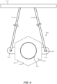
- the hanging connector 225 includes a body 246 including a first side (not shown) opposite a second side 249, the first and second sides separated by a sidewall 251.
- the hanging connector 225 may include a first connection arm (not shown)) extending from the first side and a second connection arm 262 extending from the second side 249.
- Each of the first and second connection arms is threaded to engage corresponding threading of the first and second flexible conduits (not shown).
- the hanging connector 225 further includes a pair of hanging members 253 extending outwardly from opposite portions of the sidewall 251.
- each of the hanging members 253 may be an eye loop having an opening 255 formed therein. As shown, the hanging members 253 extend outwardly at an angle parallel to the support structure 215.
- one of the hanging members 253 is connected to the support structure 215, which is located above the hanging connector 225, while another of the hanging members 253 extends to a structural wall that is perpendicular to the support structure 215.
- the hanging connector 225 further includes a pair of metallic connectors 235A-B, which may be looped through the opening 255 of each hanging member 253.
- the metallic connectors 235A-B may each be a wire or coil coupled to the support structure 215 for suspending the hanging connector 225.
- the hanging connector 325 includes a body 346 including a first side 347 opposite a second side 349, the first and second sides 347, 349 separated by a sidewall 351 extending therebetween.
- the hanging connector 325 may include a first connection arm 360 extending from the first side 347 and a second connection arm 362 extending from the second side 349.
- Each of the first and second connection arms 360, 362 has threading 361, 363 to engage corresponding threading of the first and second flexible conduits (not shown).
- the hanging connector 325 further includes a hanging member 353 extending outwardly from the sidewall 351.
- the hanging member 353 may be rectangular block having an opening formed therein for receipt of a metallic connector 335, which may be a rod.
- the metallic connector 335 may be secured within the opening of the hanging member 353 by one or more washers 337.
- the metallic connector 335 which is coupled to a support structure located above (not shown), is oriented perpendicular, or substantially perpendicular, to a length wise radial axis 'RA' extending through the center of the first and second connection arms 360, 362.
- the sprinkler assembly 400 includes many or all of the features previously described in relation to the sprinkler assembly 100 and hanging connector 125 of FIGs. 1-3 . As such, only certain aspects of the sprinkler assembly 400 will hereinafter be described for the sake of brevity.
- the sprinkler assembly 400 may include a connector (e.g., a t-joint connector) 404, indirectly joining together a sprinkler body 406 with a first flexible conduit 410.
- the sprinkler assembly 400 may further include an adjustable bracket 412 coupling the sprinkler body 406 to a ceiling 416, which is shown partially cutaway for ease of viewing.
- a thermally responsive sprinkler head 420 extends downward from the sprinkler body 406, through an opening 422 in the ceiling 416, and into an environment 424 to be protected, which may be a living/work space, or cooler/freezer.
- the sprinkler assembly 400 is configured to be mounted in a suspended manner from an overhead building support structure 415 via suitable hanger elements, such as for example, a first hanging connector 425 having a first side 447 opposite a second side 449, wherein the first hanging connector is connected to the support structure 415 by the hanging member 453 and by one or more metallic connectors 435, such as wires, cables, rods, struts, etc.
- the first hanging connector 425 joins together the first flexible conduit 410 with a second flexible conduit 445.
- the first and second flexible conduits 410, 445 are arranged linearly end-to-end such that the first and second flexible conduits 410, 445 are perpendicular, or substantially perpendicular, to the sprinkler body 406.
- the connector 404 is a right-angled joint, e.g., making the shape of the letter 'T'.
- the sprinkler body 406 is secured directly to the connector 404.
- the connector 404 may be secured directly to a second hanging connector 470, which is connected to the support structure 415 by one or more metallic connectors 472, such as wires, cables, rods, struts, etc.
- the second hanging connector 470 may be directed connected on one side to the first flexible conduit 410 (e.g., by a mounting cuff with threaded connection), and on another side to the connector 404 (e.g., by a mounting cuff with threaded connection).
- the second hanging connector 470 may be directly physically coupled to the connector 404, or connected by one or more intermediate components.
- a third hanging connector (not shown) may be directly connected at an opposite side of the connector 404.
- the sprinkler assembly 500 includes many or all of the features previously described above in relation to the sprinkler assemblies 100 and 400, and hanging connectors 125, 425, and 425. As such, only certain aspects of the sprinkler assembly 500 will hereinafter be described for the sake of brevity.
- the sprinkler assembly 500 may include a sprinkler body 506 (e.g., sprinkler drop) directly connected with a first flexible conduit 510, for example, via mounting cuff 587. In other words, no connector may be present in this embodiment.
- the sprinkler assembly 500 may further include an adjustable hub or bracket 512 coupling the sprinkler body 506 to a bracket bar 514, which in turn is coupled to one or more beams 517 by a support assembly 523.
- each of the beams 517 may be a t-shaped beam.
- a thermally responsive sprinkler head 520 extends downward from the sprinkler body 506, through an opening 522 in the ceiling 516, and into an environment 524 to be protected.
- the sprinkler assembly 500 is configured to be mounted in a suspended manner from an overhead building support structure (not shown) via suitable hanger elements, such as for example, a hanging connector 525 connected to the support structure 515 by one or more metallic connectors 535, such as wires, cables, rods, struts, etc. As shown, the hanging connector 525 joins together the first flexible conduit 510 with a second flexible conduit 545.
- the first and second flexible conduits 510, 545 are arranged linearly end-to-end such that the second flexible conduit 545 is perpendicular, or substantially perpendicular, to the sprinkler body 506.
- the hanger connectors can be affixed to a ceiling support structure, as desired, and the flexible conduits can then be secured thereto during installation.
- the hanging connector allows two flexible conduits to be reliably secured together end-to-end using a pair of opposed connection arms extending from the body of the hanging connector.
- a sprinkler assembly can comprise a sprinkler body coupled to a first flexible conduit; a hanging connector coupled to the first flexible conduit and to a second flexible conduit, the hanging connector including a hanging member extending outwardly from the hanging connector; and a metallic connector extending between the hanging member and a support structure.
- the metallic connector can extend through an opening of the hanging member.
- the hanging member can be an eye loop extending from a sidewall of the hanging connector.
- the sprinkler assembly can further comprise a sprinkler head coupled at one end of the sprinkler body; and a t-joint connector coupled at another end of the sprinkler body, wherein the t-joint connector can be directly coupled to the first flexible conduit.
- the sprinkler assembly can further comprise a first mounting cuff of the first flexible conduit secured to the hanging connector and a second mounting cuff of the second flexible conduit secured to the hanging connector.
- the hanging connector can comprise a body including a first side opposite a second side; and a first connection arm extending from the first side and a second connection arm extending from the second side.
- first connection arm and the second connection arm can include threading for connection with corresponding threading of the first and second flexible conduits.
- the t-joint connector can be directly coupled to the first connection arm or the second connection arm.
- the metallic connector can be one of a wire, a coil, or a rod.
- the sprinkler assembly can further comprise a second hanging member extending outwardly from the hanging connector; and a second metallic connector extending between the second hanging member and the support structure.
- the first flexible conduit and the second flexible conduit can be coupled together end-to-end by the hanging connector.
- a hanging connector can comprise a body including a first side opposite a second side; and a first connection arm extending from the first side and a second connection arm extending from the second side, the first side and the second side separated by a sidewall; a hanging member extending outwardly from the sidewall; and a metallic connector extending between the hanging member and a support structure.
- the metallic connector can extend through an opening of the hanging member.
- the hanging member can be an eye loop extending from a sidewall of the hanging connector.
- the metallic connector can be one of a wire, a coil, or a rod.
- the first connection arm can include threading for connection with a first flexible conduit
- the second connection arm can include threading for connection with a second flexible conduit
- the hanging connector can further comprise a second hanging member extending outwardly from the body; and a second metallic connector extending between the second hanging member and the support structure.
- a sprinkler assembly can comprise a sprinkler body coupled at one end to a sprinkler head and at another end to a first flexible conduit; a hanging connector coupled to the first flexible conduit and to a second flexible conduit, the hanging connector comprising a first side, a second side opposite the first side, and a sidewall extending between the first and second sides; a hanging member extending outwardly from the sidewall; and a first threaded connection arm extending from the first side and a second threaded connection arm extending from the second side, wherein the first flexible conduit can be secured to the first threaded connection arm and the second flexible conduit is secured to the second threaded connection arm; and a flexible metallic connector extending between the hanging member and a support structure.
- the hanging member can be an eye loop extending from the sidewall of the hanging connector, and wherein the flexible metallic connector can extend through an opening of the eye loop.
- the first and second flexible conduits can be arranged linearly end-to-end, and wherein the first and second flexible conduits can be substantially perpendicular to the sprinkler body.
- a hanging connector can comprise a body, the body defining a sidewall; and a hanging member extending outwardly from the sidewall.
Landscapes
- Engineering & Computer Science (AREA)
- General Engineering & Computer Science (AREA)
- Mechanical Engineering (AREA)
- Health & Medical Sciences (AREA)
- Public Health (AREA)
- Business, Economics & Management (AREA)
- Emergency Management (AREA)
- Fire-Extinguishing By Fire Departments, And Fire-Extinguishing Equipment And Control Thereof (AREA)
- Quick-Acting Or Multi-Walled Pipe Joints (AREA)
Claims (5)
- Ensemble (100) destiné à un système de gicleur, l'ensemble comprenant :un premier conduit flexible (110) et un deuxième conduit flexible (145) ;un corps (106) pour un gicleur, le corps (106) étant accouplé au premier conduit flexible (110) ;un connecteur suspendu (125) accouplé au premier conduit flexible (110) et au deuxième conduit flexible (145), le connecteur suspendu (125) comprenant un corps de connecteur (145) incluant un premier côté (147) opposé à un deuxième côté (149), les premier et deuxième côtés (147, 149) étant séparés par une paroi (151),dans lequel le connecteur suspendu (125) comprend un premier bras de connexion (160) doté d'un filetage et s'étendant depuis le premier côté (147), et un deuxième bras de connexion (162) doté d'un filetage et s'étendant depuis le deuxième côté (149), le premier conduit flexible (110) étant fixé au premier bras de connexion (160) et le deuxième conduit flexible (145) étant fixé au deuxième bras de connexion fileté avec un filetage correspondant des premier et deuxième conduits flexibles (110, 145), respectivement,le connecteur suspendu (125) comprenant un élément suspendu (153), l'élément suspendu (153) s'étendant vers l'extérieur depuis la paroi (151) du connecteur suspendu (125), l'élément suspendu (153) étant une boucle-œil dotée d'une ouverture (155) formée à l'intérieur ; etun connecteur métallique (135) s'étendant entre l'ouverture (155) de l'élément suspendu (125) et une structure de support (115).
- Ensemble gicleur selon la revendication 1, dans lequel le connecteur métallique (135) est l'un parmi : un fil, une bobine et une tige.
- Ensemble gicleur selon la revendication 1, comprenant en outre :un deuxième élément suspendu qui s'étend vers l'extérieur depuis le connecteur suspendu (125) ; etun deuxième connecteur métallique qui s'étend entre le deuxième élément suspendu (153) et la structure de support.
- Ensemble gicleur selon la revendication 1, comprenant :
le corps (106) accouplé au niveau d'une extrémité à une tête de gicleur et au niveau d'une autre extrémité au premier conduit flexible (110). - Ensemble gicleur selon la revendication 1, dans lequel le connecteur métallique (135) est flexible, le connecteur métallique flexible s'étendant à travers l'ouverture de la boucle-œil.
Priority Applications (1)
| Application Number | Priority Date | Filing Date | Title |
|---|---|---|---|
| EP23187160.9A EP4239236A3 (fr) | 2017-07-07 | 2018-07-05 | Ensemble pour un système d'arroseur |
Applications Claiming Priority (2)
| Application Number | Priority Date | Filing Date | Title |
|---|---|---|---|
| US15/644,141 US10981189B2 (en) | 2017-07-07 | 2017-07-07 | Hanging connector for flexible sprinkler conduit |
| PCT/US2018/040938 WO2019010319A1 (fr) | 2017-07-07 | 2018-07-05 | Raccord suspendu pour conduit de gicleur d'incendie souple |
Related Child Applications (2)
| Application Number | Title | Priority Date | Filing Date |
|---|---|---|---|
| EP23187160.9A Division EP4239236A3 (fr) | 2017-07-07 | 2018-07-05 | Ensemble pour un système d'arroseur |
| EP23187160.9A Division-Into EP4239236A3 (fr) | 2017-07-07 | 2018-07-05 | Ensemble pour un système d'arroseur |
Publications (4)
| Publication Number | Publication Date |
|---|---|
| EP3645131A1 EP3645131A1 (fr) | 2020-05-06 |
| EP3645131A4 EP3645131A4 (fr) | 2021-06-16 |
| EP3645131C0 EP3645131C0 (fr) | 2023-08-30 |
| EP3645131B1 true EP3645131B1 (fr) | 2023-08-30 |
Family
ID=64903892
Family Applications (2)
| Application Number | Title | Priority Date | Filing Date |
|---|---|---|---|
| EP23187160.9A Pending EP4239236A3 (fr) | 2017-07-07 | 2018-07-05 | Ensemble pour un système d'arroseur |
| EP18829045.6A Active EP3645131B1 (fr) | 2017-07-07 | 2018-07-05 | Ensemble pour un système de gicleurs |
Family Applications Before (1)
| Application Number | Title | Priority Date | Filing Date |
|---|---|---|---|
| EP23187160.9A Pending EP4239236A3 (fr) | 2017-07-07 | 2018-07-05 | Ensemble pour un système d'arroseur |
Country Status (7)
| Country | Link |
|---|---|
| US (2) | US10981189B2 (fr) |
| EP (2) | EP4239236A3 (fr) |
| AU (3) | AU2018297290B2 (fr) |
| CA (1) | CA3069145A1 (fr) |
| ES (1) | ES2959772T3 (fr) |
| MX (2) | MX393274B (fr) |
| WO (1) | WO2019010319A1 (fr) |
Families Citing this family (8)
| Publication number | Priority date | Publication date | Assignee | Title |
|---|---|---|---|---|
| US10981189B2 (en) | 2017-07-07 | 2021-04-20 | Anvil International, Llc | Hanging connector for flexible sprinkler conduit |
| USD854915S1 (en) | 2017-11-08 | 2019-07-30 | Anvil International, Llc | Conduit hanger adapter |
| WO2022192158A1 (fr) | 2021-03-08 | 2022-09-15 | Tyco Fire Products Lp | Systèmes et procédés pour des systèmes gicleurs d'incendie comprenant un tuyau souple et un adaptateur de joint rapide |
| CN113440776A (zh) * | 2021-03-14 | 2021-09-28 | 武汉市万方众成科技有限公司 | 一种小程序后台服务器用消防装置 |
| CN113446462B (zh) * | 2021-07-07 | 2022-10-14 | 重庆海科保温材料有限公司 | 低温管道吊装部隔热支撑结构 |
| JP7783767B2 (ja) | 2022-03-24 | 2025-12-10 | 日本ドライケミカル株式会社 | ハウジング形継手の冷却システム |
| AU2024242156A1 (en) * | 2023-03-30 | 2025-10-16 | Rite-Hite Holding Corporation | Apparatus to support externally tensioned pliable air ducts |
| CN116290678B (zh) * | 2023-04-27 | 2023-08-25 | 河北中顺基润环保科技有限公司 | 一种环保建筑涂料喷涂设备 |
Family Cites Families (73)
| Publication number | Priority date | Publication date | Assignee | Title |
|---|---|---|---|---|
| US884661A (en) * | 1908-02-06 | 1908-04-14 | Standard Malleable Iron Company | Pipe bracket or support. |
| US1052837A (en) * | 1911-12-01 | 1913-02-11 | Makutchan Roller Bearing Company | Hanger. |
| US1760224A (en) * | 1928-12-22 | 1930-05-27 | James A Wray | Swivel |
| US1838623A (en) * | 1931-05-15 | 1931-12-29 | Jr Henry J Hersey | Supporting means for flexible tubing |
| US2246557A (en) * | 1939-02-18 | 1941-06-24 | Louis G Walters | Bus connector |
| US2698760A (en) * | 1949-02-28 | 1955-01-04 | Grant V W Roth | Flexible connection |
| US3194590A (en) * | 1963-06-24 | 1965-07-13 | Heath Tecna Plastics Inc | Combination pipe hanger and coupling |
| US3244388A (en) * | 1964-01-20 | 1966-04-05 | Jack W Coffman | Insulated pipe hanger construction |
| DE1268918B (de) * | 1964-11-18 | 1968-05-22 | Franz Johann Jakob Mueller | Aufhaengeeinrichtung fuer Rohrleitungen mit einer Rohrschelle und einem Aufhaengeband |
| US3414220A (en) * | 1966-12-30 | 1968-12-03 | Hydro Craft Inc | Clamp means |
| US3539139A (en) * | 1968-06-10 | 1970-11-10 | Preformed Line Products Co | Appliance for linear bodies |
| US3838712A (en) * | 1972-11-30 | 1974-10-01 | Bendix Corp | Structural fitting for filament composite tubular member |
| US3960350A (en) * | 1973-11-27 | 1976-06-01 | Electrovert Ltd. | Shock-resisting hanger systems and suspended assemblies |
| US4834186A (en) * | 1987-10-19 | 1989-05-30 | Ballard Estus E | Sprinkler head mounting system |
| US4793578A (en) * | 1987-11-09 | 1988-12-27 | Howard Harold L | Multiple conduit support system |
| USD332481S (en) | 1990-03-30 | 1993-01-12 | Elconnex Pty. Limited | Connector for corrugated plastic pipe |
| JPH07114819B2 (ja) * | 1990-04-23 | 1995-12-13 | 五十鈴工業株式会社 | スプリンクラーヘッド取付用配管の施工方法とスプリンクラーヘッド取付用配管構造 |
| US5209440A (en) * | 1991-07-22 | 1993-05-11 | Hydro-Craft, Inc. | Hexagonal junction adapter with retaining shoulder |
| US5226456A (en) * | 1991-12-09 | 1993-07-13 | Semak Mark A | Support for length of flexible or light gauge hose or piping |
| US5344108A (en) * | 1992-05-14 | 1994-09-06 | Tolco, Incorporated | Pipe surge restrainer for use with pipe hanger |
| US5474274A (en) * | 1993-10-22 | 1995-12-12 | Bernosky; John | Coupling and load support for suspending a load from the head of a coal mine roof bolt |
| US5702077A (en) * | 1995-05-09 | 1997-12-30 | Tolco, Incorporated | Threaded bracket for hanger rod |
| US6086029A (en) * | 1997-08-25 | 2000-07-11 | Oliver Systems International, Inc. | Support system for wood framed construction |
| US6135397A (en) * | 1997-10-15 | 2000-10-24 | Santa Cruz; Cathy D. | Multipurpose fastener |
| USD397413S (en) | 1997-12-15 | 1998-08-25 | Sapp Paul S | Pipe fitting |
| US6488097B1 (en) * | 1999-01-08 | 2002-12-03 | Pnm, Inc. | Fire protection sprinkler head support |
| JP2000317008A (ja) | 1999-05-06 | 2000-11-21 | Nohmi Bosai Ltd | スプリンクラ消火設備及びその施工方法 |
| WO2001044622A1 (fr) * | 1999-12-14 | 2001-06-21 | Yury Sherman | Systeme de support substantiel de structures lineaires rigides |
| US6158519A (en) * | 2000-01-18 | 2000-12-12 | Kretschmer; Alan P. | Fire suppression method and apparatus |
| JP2002239024A (ja) * | 2001-02-16 | 2002-08-27 | Nippon Kokan Pipe Fittings Mfg Co Ltd | スプリンクラーヘッドの固定金具 |
| US7793988B1 (en) | 2001-05-04 | 2010-09-14 | Sami Shemtov | Connector for electrical wire-carrying conduits |
| US6484976B1 (en) * | 2001-05-15 | 2002-11-26 | Gkn Automotive, Inc. | Center bearing hanger assembly |
| KR100406715B1 (ko) * | 2001-06-25 | 2003-11-20 | 동아금속주름관(주) | 스프링클러용 플렉시블 튜브의 보호망 결합구조 및 그결합방법 |
| US6896301B2 (en) * | 2002-11-12 | 2005-05-24 | Master Pneumatic-Detroit, Inc. | Clamp assembly |
| DE20218285U1 (de) * | 2002-11-25 | 2004-01-15 | Betschart, Anton-Peter, Dr.-Ing. Architekt | Abhängevorrichtungen |
| US20050051674A1 (en) * | 2003-09-10 | 2005-03-10 | Winston Breeden | Pipe surge protector and hanger support |
| USD544448S1 (en) | 2004-07-30 | 2007-06-12 | The Lamson & Sessions Co. | Transition adapter for electrical conduit |
| USD533259S1 (en) | 2005-03-14 | 2006-12-05 | Charlotte Pipe And Foundry Company | Portion of a pipe fitting |
| CN101147024B (zh) * | 2005-03-24 | 2010-05-19 | 尼尔·安德鲁·罗伯茨 | 安装或移除构件时使用的临时支撑结构 |
| WO2007075631A2 (fr) * | 2005-12-20 | 2007-07-05 | Erico International Corporation | Bride de suspension pourvue d’une bande de suspension |
| US7914048B2 (en) | 2006-03-02 | 2011-03-29 | Sami Shemtov | Liquid-tight coupling device with screw-on ferrule device and method of use |
| US7665674B2 (en) * | 2007-03-30 | 2010-02-23 | Yong Won E.N.C. Ltd. | Structure for fixing reducer for sprinkler in side wall |
| US20090224533A1 (en) | 2008-03-10 | 2009-09-10 | Richter James R | Support system for flexible pipe |
| US8016028B2 (en) * | 2008-03-29 | 2011-09-13 | Delafield Corporation | Apparatus for flexibly restraining service loops in an oil derrick to prevent entangling of the loops |
| USD583026S1 (en) | 2008-07-08 | 2008-12-16 | Praher Canada Products Ltd. | High temperature disconnect union |
| US20100038494A1 (en) * | 2008-08-13 | 2010-02-18 | Osborn Eric C | Loop hanger with integral washer |
| CA2684162C (fr) * | 2008-10-31 | 2017-04-25 | Nibco Inc. | Ensemble de renforcement sismique |
| US8056938B2 (en) | 2009-04-16 | 2011-11-15 | Royal Group Inc. | Fitting for corrugated conduit |
| CA2761532A1 (fr) * | 2009-05-08 | 2010-11-11 | Uponor Innovation Ab | Console support |
| AR078273A1 (es) * | 2009-09-11 | 2011-10-26 | Victaulic Co Of America | Conjunto flexible para rociadores |
| USD647784S1 (en) | 2010-10-13 | 2011-11-01 | Mueller International, Llc | Conduit hanger |
| US9709192B1 (en) * | 2011-04-08 | 2017-07-18 | Com Dangles, Llc | Strap for suspending wires that is reconfigurable for various attachment systems |
| USD659644S1 (en) | 2011-04-20 | 2012-05-15 | Arlington Industries, Inc. | Cable connector |
| US8752575B2 (en) | 2012-07-17 | 2014-06-17 | Moen Incorporated | Faucet including cartridge assembly with radially offset key |
| US8875743B2 (en) * | 2012-08-24 | 2014-11-04 | Nordson Corporation | Hanger and method for routing a hot melt hose |
| US9140277B2 (en) * | 2012-09-27 | 2015-09-22 | New Pig Corporation | Quick-attaching ceiling leak diverter devices |
| USD724699S1 (en) | 2012-12-05 | 2015-03-17 | Mark W. Wyne | Nozzle adaptor |
| US9371948B2 (en) | 2013-08-14 | 2016-06-21 | Heyco, Inc. | Liquid-tight connector |
| AU2014306551A1 (en) * | 2013-08-14 | 2016-02-25 | Jbt Steel Industries, Inc. | Method and apparatus for suspending duct by inserted corner members |
| KR101366180B1 (ko) | 2013-09-12 | 2014-02-28 | 승진산업 (주) | 무용접 방폭용 케이블 그랜드 조립체 |
| USD787648S1 (en) | 2013-10-31 | 2017-05-23 | Bridgeport Fittings, Inc. | Raintight fitting connector body |
| USD754303S1 (en) | 2014-07-03 | 2016-04-19 | Bridgeport Fittings, Inc. | Side load conduit connector |
| ITUB20153740A1 (it) * | 2015-09-18 | 2017-03-18 | Raffaello Bosis | Dispositivo di trattenimento e sicurezza per tubi flessibili in pressione |
| USD779046S1 (en) | 2015-09-21 | 2017-02-14 | Fountain Master, Llc | Threaded connector |
| JP2017061262A (ja) * | 2015-09-25 | 2017-03-30 | 豊田合成株式会社 | 燃料供給装置 |
| USD777885S1 (en) | 2015-12-03 | 2017-01-31 | Ningbo Aoleishi Sanitary Ware Co., Ltd. | Quick-install mechanism above countertop for faucet |
| US20170184222A1 (en) * | 2015-12-28 | 2017-06-29 | Seth E. Aker | Pipe Suspension Clamp Hanger |
| USD822180S1 (en) | 2016-03-10 | 2018-07-03 | Mustang Sampling, Llc | Pipe fitting |
| USD832222S1 (en) | 2016-09-26 | 2018-10-30 | Switchboard Apparatus, Inc. | Insulator |
| US10279367B2 (en) | 2016-10-11 | 2019-05-07 | Anvil International, Llc | Sprinkler assembly connector for flexible conduit |
| US9951821B1 (en) | 2017-01-11 | 2018-04-24 | Crossford International, Llc | Drive shaft coupling |
| US10981189B2 (en) | 2017-07-07 | 2021-04-20 | Anvil International, Llc | Hanging connector for flexible sprinkler conduit |
| USD854915S1 (en) | 2017-11-08 | 2019-07-30 | Anvil International, Llc | Conduit hanger adapter |
-
2017
- 2017-07-07 US US15/644,141 patent/US10981189B2/en active Active
-
2018
- 2018-07-05 EP EP23187160.9A patent/EP4239236A3/fr active Pending
- 2018-07-05 EP EP18829045.6A patent/EP3645131B1/fr active Active
- 2018-07-05 MX MX2020000245A patent/MX393274B/es unknown
- 2018-07-05 WO PCT/US2018/040938 patent/WO2019010319A1/fr not_active Ceased
- 2018-07-05 CA CA3069145A patent/CA3069145A1/fr active Pending
- 2018-07-05 ES ES18829045T patent/ES2959772T3/es active Active
- 2018-07-05 AU AU2018297290A patent/AU2018297290B2/en active Active
-
2020
- 2020-01-08 MX MX2022002807A patent/MX2022002807A/es unknown
-
2021
- 2021-03-24 US US17/210,594 patent/US20210205833A1/en active Pending
-
2023
- 2023-11-30 AU AU2023274179A patent/AU2023274179B2/en active Active
-
2026
- 2026-02-27 AU AU2026201547A patent/AU2026201547A1/en active Pending
Also Published As
| Publication number | Publication date |
|---|---|
| US10981189B2 (en) | 2021-04-20 |
| MX2022002807A (es) | 2022-04-01 |
| EP4239236A3 (fr) | 2023-11-01 |
| EP3645131A1 (fr) | 2020-05-06 |
| US20190009295A1 (en) | 2019-01-10 |
| US20210205833A1 (en) | 2021-07-08 |
| AU2023274179A1 (en) | 2023-12-21 |
| CA3069145A1 (fr) | 2019-01-10 |
| AU2023274179B2 (en) | 2025-11-27 |
| AU2026201547A1 (en) | 2026-03-19 |
| MX393274B (es) | 2025-03-24 |
| EP4239236A2 (fr) | 2023-09-06 |
| EP3645131C0 (fr) | 2023-08-30 |
| EP3645131A4 (fr) | 2021-06-16 |
| AU2018297290A1 (en) | 2020-01-30 |
| MX2020000245A (es) | 2022-06-20 |
| ES2959772T3 (es) | 2024-02-28 |
| WO2019010319A1 (fr) | 2019-01-10 |
| AU2018297290B2 (en) | 2023-08-31 |
Similar Documents
| Publication | Publication Date | Title |
|---|---|---|
| AU2018297290B2 (en) | Hanging connector for flexible sprinkler conduit | |
| US11383262B2 (en) | Sprinkler assembly connector for flexible conduit | |
| US10835772B2 (en) | Sprinkler drop bracket for intersecting downlight | |
| KR101766353B1 (ko) | 스프링클러용 가요성 조립체 | |
| US6691790B1 (en) | Fire-suppression sprinkler system and method for installation and retrofit | |
| US9874297B2 (en) | Pipe/conduit hanging device | |
| WO2002031937A9 (fr) | Gouttieres, raccords et couplages de cable optique | |
| KR102423972B1 (ko) | 공동주택의 소방 배관 설치구조 | |
| KR101344081B1 (ko) | 스프링클러 헤드 플레이트 | |
| EP3972702B1 (fr) | Verrou de serrage supérieur de support d'arroseur | |
| KR102550445B1 (ko) | 소방 배관 설치구조 | |
| US20230258362A1 (en) | Duct Replacement Device and Method of Use | |
| US12239866B2 (en) | Sprinkler box for embedded sprinkler pipe system | |
| JP2015197182A (ja) | 分岐継手 | |
| ES2243161T3 (es) | Red de distribucion de agua corriente integrada con alimentacion en paralelo para agua de uso domestico y extincion de incendios. | |
| JP3700107B2 (ja) | スプリンクラ消火設備 | |
| KR200253910Y1 (ko) | 공동주택용 스프링쿨러 고정장치 | |
| EP3972703B1 (fr) | Support d'extincteur à verrou de serrage | |
| JP3937379B2 (ja) | スプリンクラ消火設備 | |
| CN100557908C (zh) | 用于分隔物内设备的防火装置 | |
| JP5771016B2 (ja) | 継手 | |
| JP2001276267A (ja) | 消火設備 | |
| JP6498596B2 (ja) | 感熱開放継手 |
Legal Events
| Date | Code | Title | Description |
|---|---|---|---|
| STAA | Information on the status of an ep patent application or granted ep patent |
Free format text: STATUS: THE INTERNATIONAL PUBLICATION HAS BEEN MADE |
|
| PUAI | Public reference made under article 153(3) epc to a published international application that has entered the european phase |
Free format text: ORIGINAL CODE: 0009012 |
|
| STAA | Information on the status of an ep patent application or granted ep patent |
Free format text: STATUS: REQUEST FOR EXAMINATION WAS MADE |
|
| 17P | Request for examination filed |
Effective date: 20200131 |
|
| AK | Designated contracting states |
Kind code of ref document: A1 Designated state(s): AL AT BE BG CH CY CZ DE DK EE ES FI FR GB GR HR HU IE IS IT LI LT LU LV MC MK MT NL NO PL PT RO RS SE SI SK SM TR |
|
| AX | Request for extension of the european patent |
Extension state: BA ME |
|
| DAV | Request for validation of the european patent (deleted) | ||
| DAX | Request for extension of the european patent (deleted) | ||
| A4 | Supplementary search report drawn up and despatched |
Effective date: 20210519 |
|
| RIC1 | Information provided on ipc code assigned before grant |
Ipc: A62C 31/00 20060101AFI20210512BHEP Ipc: A62C 35/00 20060101ALI20210512BHEP Ipc: A62C 37/00 20060101ALI20210512BHEP Ipc: F16L 3/00 20060101ALI20210512BHEP Ipc: A62C 35/68 20060101ALI20210512BHEP Ipc: A62C 37/11 20060101ALI20210512BHEP Ipc: F16L 3/133 20060101ALI20210512BHEP Ipc: F16L 15/08 20060101ALI20210512BHEP |
|
| RAP3 | Party data changed (applicant data changed or rights of an application transferred) |
Owner name: ASC ENGINEERED SOLUTIONS, LLC |
|
| STAA | Information on the status of an ep patent application or granted ep patent |
Free format text: STATUS: EXAMINATION IS IN PROGRESS |
|
| 17Q | First examination report despatched |
Effective date: 20221018 |
|
| RAP3 | Party data changed (applicant data changed or rights of an application transferred) |
Owner name: ASC ENGINEERED SOLUTIONS, LLC |
|
| GRAP | Despatch of communication of intention to grant a patent |
Free format text: ORIGINAL CODE: EPIDOSNIGR1 |
|
| STAA | Information on the status of an ep patent application or granted ep patent |
Free format text: STATUS: GRANT OF PATENT IS INTENDED |
|
| INTG | Intention to grant announced |
Effective date: 20230406 |
|
| GRAS | Grant fee paid |
Free format text: ORIGINAL CODE: EPIDOSNIGR3 |
|
| GRAA | (expected) grant |
Free format text: ORIGINAL CODE: 0009210 |
|
| STAA | Information on the status of an ep patent application or granted ep patent |
Free format text: STATUS: THE PATENT HAS BEEN GRANTED |
|
| AK | Designated contracting states |
Kind code of ref document: B1 Designated state(s): AL AT BE BG CH CY CZ DE DK EE ES FI FR GB GR HR HU IE IS IT LI LT LU LV MC MK MT NL NO PL PT RO RS SE SI SK SM TR |
|
| REG | Reference to a national code |
Ref country code: GB Ref legal event code: FG4D |
|
| REG | Reference to a national code |
Ref country code: CH Ref legal event code: EP |
|
| REG | Reference to a national code |
Ref country code: DE Ref legal event code: R096 Ref document number: 602018056590 Country of ref document: DE |
|
| REG | Reference to a national code |
Ref country code: IE Ref legal event code: FG4D |
|
| U01 | Request for unitary effect filed |
Effective date: 20230926 |
|
| U07 | Unitary effect registered |
Designated state(s): AT BE BG DE DK EE FI FR IT LT LU LV MT NL PT SE SI Effective date: 20231002 |
|
| PG25 | Lapsed in a contracting state [announced via postgrant information from national office to epo] |
Ref country code: GR Free format text: LAPSE BECAUSE OF FAILURE TO SUBMIT A TRANSLATION OF THE DESCRIPTION OR TO PAY THE FEE WITHIN THE PRESCRIBED TIME-LIMIT Effective date: 20231201 |
|
| PG25 | Lapsed in a contracting state [announced via postgrant information from national office to epo] |
Ref country code: IS Free format text: LAPSE BECAUSE OF FAILURE TO SUBMIT A TRANSLATION OF THE DESCRIPTION OR TO PAY THE FEE WITHIN THE PRESCRIBED TIME-LIMIT Effective date: 20231230 |
|
| PG25 | Lapsed in a contracting state [announced via postgrant information from national office to epo] |
Ref country code: RS Free format text: LAPSE BECAUSE OF FAILURE TO SUBMIT A TRANSLATION OF THE DESCRIPTION OR TO PAY THE FEE WITHIN THE PRESCRIBED TIME-LIMIT Effective date: 20230830 Ref country code: NO Free format text: LAPSE BECAUSE OF FAILURE TO SUBMIT A TRANSLATION OF THE DESCRIPTION OR TO PAY THE FEE WITHIN THE PRESCRIBED TIME-LIMIT Effective date: 20231130 Ref country code: IS Free format text: LAPSE BECAUSE OF FAILURE TO SUBMIT A TRANSLATION OF THE DESCRIPTION OR TO PAY THE FEE WITHIN THE PRESCRIBED TIME-LIMIT Effective date: 20231230 Ref country code: HR Free format text: LAPSE BECAUSE OF FAILURE TO SUBMIT A TRANSLATION OF THE DESCRIPTION OR TO PAY THE FEE WITHIN THE PRESCRIBED TIME-LIMIT Effective date: 20230830 Ref country code: GR Free format text: LAPSE BECAUSE OF FAILURE TO SUBMIT A TRANSLATION OF THE DESCRIPTION OR TO PAY THE FEE WITHIN THE PRESCRIBED TIME-LIMIT Effective date: 20231201 |
|
| REG | Reference to a national code |
Ref country code: ES Ref legal event code: FG2A Ref document number: 2959772 Country of ref document: ES Kind code of ref document: T3 Effective date: 20240228 |
|
| PG25 | Lapsed in a contracting state [announced via postgrant information from national office to epo] |
Ref country code: PL Free format text: LAPSE BECAUSE OF FAILURE TO SUBMIT A TRANSLATION OF THE DESCRIPTION OR TO PAY THE FEE WITHIN THE PRESCRIBED TIME-LIMIT Effective date: 20230830 |
|
| PG25 | Lapsed in a contracting state [announced via postgrant information from national office to epo] |
Ref country code: SM Free format text: LAPSE BECAUSE OF FAILURE TO SUBMIT A TRANSLATION OF THE DESCRIPTION OR TO PAY THE FEE WITHIN THE PRESCRIBED TIME-LIMIT Effective date: 20230830 Ref country code: RO Free format text: LAPSE BECAUSE OF FAILURE TO SUBMIT A TRANSLATION OF THE DESCRIPTION OR TO PAY THE FEE WITHIN THE PRESCRIBED TIME-LIMIT Effective date: 20230830 Ref country code: CZ Free format text: LAPSE BECAUSE OF FAILURE TO SUBMIT A TRANSLATION OF THE DESCRIPTION OR TO PAY THE FEE WITHIN THE PRESCRIBED TIME-LIMIT Effective date: 20230830 Ref country code: SK Free format text: LAPSE BECAUSE OF FAILURE TO SUBMIT A TRANSLATION OF THE DESCRIPTION OR TO PAY THE FEE WITHIN THE PRESCRIBED TIME-LIMIT Effective date: 20230830 |
|
| REG | Reference to a national code |
Ref country code: DE Ref legal event code: R097 Ref document number: 602018056590 Country of ref document: DE |
|
| PLBE | No opposition filed within time limit |
Free format text: ORIGINAL CODE: 0009261 |
|
| STAA | Information on the status of an ep patent application or granted ep patent |
Free format text: STATUS: NO OPPOSITION FILED WITHIN TIME LIMIT |
|
| 26N | No opposition filed |
Effective date: 20240603 |
|
| U20 | Renewal fee for the european patent with unitary effect paid |
Year of fee payment: 7 Effective date: 20240711 |
|
| PG25 | Lapsed in a contracting state [announced via postgrant information from national office to epo] |
Ref country code: MC Free format text: LAPSE BECAUSE OF FAILURE TO SUBMIT A TRANSLATION OF THE DESCRIPTION OR TO PAY THE FEE WITHIN THE PRESCRIBED TIME-LIMIT Effective date: 20230830 |
|
| REG | Reference to a national code |
Ref country code: CH Ref legal event code: PL |
|
| PG25 | Lapsed in a contracting state [announced via postgrant information from national office to epo] |
Ref country code: CH Free format text: LAPSE BECAUSE OF NON-PAYMENT OF DUE FEES Effective date: 20240731 |
|
| U20 | Renewal fee for the european patent with unitary effect paid |
Year of fee payment: 8 Effective date: 20250725 |
|
| PGFP | Annual fee paid to national office [announced via postgrant information from national office to epo] |
Ref country code: ES Payment date: 20250801 Year of fee payment: 8 |
|
| PGFP | Annual fee paid to national office [announced via postgrant information from national office to epo] |
Ref country code: GB Payment date: 20250725 Year of fee payment: 8 |
|
| PGFP | Annual fee paid to national office [announced via postgrant information from national office to epo] |
Ref country code: IE Payment date: 20250725 Year of fee payment: 8 |
|
| PG25 | Lapsed in a contracting state [announced via postgrant information from national office to epo] |
Ref country code: CY Free format text: LAPSE BECAUSE OF FAILURE TO SUBMIT A TRANSLATION OF THE DESCRIPTION OR TO PAY THE FEE WITHIN THE PRESCRIBED TIME-LIMIT; INVALID AB INITIO Effective date: 20180705 |
|
| PG25 | Lapsed in a contracting state [announced via postgrant information from national office to epo] |
Ref country code: HU Free format text: LAPSE BECAUSE OF FAILURE TO SUBMIT A TRANSLATION OF THE DESCRIPTION OR TO PAY THE FEE WITHIN THE PRESCRIBED TIME-LIMIT; INVALID AB INITIO Effective date: 20180705 |