EP3645189B1 - Procédé de fabrication d'une pièce composite en acier ainsi que pièce composite en acier - Google Patents
Procédé de fabrication d'une pièce composite en acier ainsi que pièce composite en acier Download PDFInfo
- Publication number
- EP3645189B1 EP3645189B1 EP18725490.9A EP18725490A EP3645189B1 EP 3645189 B1 EP3645189 B1 EP 3645189B1 EP 18725490 A EP18725490 A EP 18725490A EP 3645189 B1 EP3645189 B1 EP 3645189B1
- Authority
- EP
- European Patent Office
- Prior art keywords
- steel component
- press
- component
- predetermined breaking
- breaking point
- Prior art date
- Legal status (The legal status is an assumption and is not a legal conclusion. Google has not performed a legal analysis and makes no representation as to the accuracy of the status listed.)
- Active
Links
Images

Classifications
-
- B—PERFORMING OPERATIONS; TRANSPORTING
- B21—MECHANICAL METAL-WORKING WITHOUT ESSENTIALLY REMOVING MATERIAL; PUNCHING METAL
- B21J—FORGING; HAMMERING; PRESSING METAL; RIVETING; FORGE FURNACES
- B21J5/00—Methods for forging, hammering, or pressing; Special equipment or accessories therefor
- B21J5/06—Methods for forging, hammering, or pressing; Special equipment or accessories therefor for performing particular operations
- B21J5/063—Friction heat forging
- B21J5/066—Flow drilling
-
- B—PERFORMING OPERATIONS; TRANSPORTING
- B21—MECHANICAL METAL-WORKING WITHOUT ESSENTIALLY REMOVING MATERIAL; PUNCHING METAL
- B21D—WORKING OR PROCESSING OF SHEET METAL OR METAL TUBES, RODS OR PROFILES WITHOUT ESSENTIALLY REMOVING MATERIAL; PUNCHING METAL
- B21D39/00—Application of procedures in order to connect objects or parts, e.g. coating with sheet metal otherwise than by plating; Tube expanders
- B21D39/03—Application of procedures in order to connect objects or parts, e.g. coating with sheet metal otherwise than by plating; Tube expanders of sheet metal otherwise than by folding
-
- B—PERFORMING OPERATIONS; TRANSPORTING
- B21—MECHANICAL METAL-WORKING WITHOUT ESSENTIALLY REMOVING MATERIAL; PUNCHING METAL
- B21D—WORKING OR PROCESSING OF SHEET METAL OR METAL TUBES, RODS OR PROFILES WITHOUT ESSENTIALLY REMOVING MATERIAL; PUNCHING METAL
- B21D39/00—Application of procedures in order to connect objects or parts, e.g. coating with sheet metal otherwise than by plating; Tube expanders
- B21D39/06—Application of procedures in order to connect objects or parts, e.g. coating with sheet metal otherwise than by plating; Tube expanders of tubes in openings, e.g. rolling-in
-
- B—PERFORMING OPERATIONS; TRANSPORTING
- B21—MECHANICAL METAL-WORKING WITHOUT ESSENTIALLY REMOVING MATERIAL; PUNCHING METAL
- B21K—MAKING FORGED OR PRESSED METAL PRODUCTS, e.g. HORSE-SHOES, RIVETS, BOLTS OR WHEELS
- B21K25/00—Uniting components to form integral members, e.g. turbine wheels and shafts, caulks with inserts, with or without shaping of the components
-
- B—PERFORMING OPERATIONS; TRANSPORTING
- B21—MECHANICAL METAL-WORKING WITHOUT ESSENTIALLY REMOVING MATERIAL; PUNCHING METAL
- B21D—WORKING OR PROCESSING OF SHEET METAL OR METAL TUBES, RODS OR PROFILES WITHOUT ESSENTIALLY REMOVING MATERIAL; PUNCHING METAL
- B21D28/00—Shaping by press-cutting; Perforating
- B21D28/24—Perforating, i.e. punching holes
-
- F—MECHANICAL ENGINEERING; LIGHTING; HEATING; WEAPONS; BLASTING
- F16—ENGINEERING ELEMENTS AND UNITS; GENERAL MEASURES FOR PRODUCING AND MAINTAINING EFFECTIVE FUNCTIONING OF MACHINES OR INSTALLATIONS; THERMAL INSULATION IN GENERAL
- F16B—DEVICES FOR FASTENING OR SECURING CONSTRUCTIONAL ELEMENTS OR MACHINE PARTS TOGETHER, e.g. NAILS, BOLTS, CIRCLIPS, CLAMPS, CLIPS OR WEDGES; JOINTS OR JOINTING
- F16B11/00—Connecting constructional elements or machine parts by sticking or pressing them together, e.g. cold pressure welding
- F16B11/006—Connecting constructional elements or machine parts by sticking or pressing them together, e.g. cold pressure welding by gluing
-
- F—MECHANICAL ENGINEERING; LIGHTING; HEATING; WEAPONS; BLASTING
- F16—ENGINEERING ELEMENTS AND UNITS; GENERAL MEASURES FOR PRODUCING AND MAINTAINING EFFECTIVE FUNCTIONING OF MACHINES OR INSTALLATIONS; THERMAL INSULATION IN GENERAL
- F16B—DEVICES FOR FASTENING OR SECURING CONSTRUCTIONAL ELEMENTS OR MACHINE PARTS TOGETHER, e.g. NAILS, BOLTS, CIRCLIPS, CLAMPS, CLIPS OR WEDGES; JOINTS OR JOINTING
- F16B25/00—Screws that cut thread in the body into which they are screwed, e.g. wood screws
- F16B25/001—Screws that cut thread in the body into which they are screwed, e.g. wood screws characterised by the material of the body into which the screw is screwed
- F16B25/0021—Screws that cut thread in the body into which they are screwed, e.g. wood screws characterised by the material of the body into which the screw is screwed the material being metal, e.g. sheet-metal or aluminium
-
- F—MECHANICAL ENGINEERING; LIGHTING; HEATING; WEAPONS; BLASTING
- F16—ENGINEERING ELEMENTS AND UNITS; GENERAL MEASURES FOR PRODUCING AND MAINTAINING EFFECTIVE FUNCTIONING OF MACHINES OR INSTALLATIONS; THERMAL INSULATION IN GENERAL
- F16B—DEVICES FOR FASTENING OR SECURING CONSTRUCTIONAL ELEMENTS OR MACHINE PARTS TOGETHER, e.g. NAILS, BOLTS, CIRCLIPS, CLAMPS, CLIPS OR WEDGES; JOINTS OR JOINTING
- F16B25/00—Screws that cut thread in the body into which they are screwed, e.g. wood screws
- F16B25/10—Screws performing an additional function to thread-forming, e.g. drill screws or self-piercing screws
- F16B25/106—Screws performing an additional function to thread-forming, e.g. drill screws or self-piercing screws by means of a self-piercing screw-point, i.e. without removing material
Definitions
- the invention relates to a method for producing a composite steel component and a composite steel component.
- a press-hardened sheet metal component with at least one predetermined breaking point is known.
- the predetermined breaking point is an overhardened component area, which is provided to absorb energy from breaking in the event of a crash load. This allows collision energy to be diverted specifically to other components.
- the press-hardened sheet metal component can be joined together with other components in a component assembly.
- the object of the present invention is to create a method for producing a steel component composite and a steel component composite which can be produced particularly easily and particularly quickly.
- this object is achieved by a method for producing a composite steel component and by a composite steel component having the features of the independent claims.
- Advantageous embodiments of the invention are the subject of the dependent claims and the description.
- a steel component is provided with a predetermined breaking point and the predetermined breaking point of the steel component is punched into an opening by means of a press-in element.
- the press-in element is then pressed into the opening of the steel component and, at least in overlap with the press-in element, a component is glued to the steel component by means of an adhesive applied over the surface. Then a flow hole is melted through the press-fit element, the steel component and the component by means of a flow drilling element.
- the steel component which is in particular a press-hardened steel component for a motor vehicle, becomes the predetermined breaking point during a manufacturing process of the press-hardened steel component Mistake.
- the press-in element is then brought up to the predetermined breaking point of the steel component in such a way that pressure can be exerted on the predetermined breaking point by means of the press-in element and the predetermined breaking point is thereby punched into the opening.
- the press-in element is pressed into the opening of the steel component, so that the opening is filled in particular with the press-in element.
- the adhesive is then applied flatly to the steel component and / or the component, in particular in a region of the press-in element, and the steel component is arranged in contact with the component.
- the steel component is at least in the area in which the press-in element is arranged, in overlap with the component.
- the flow drilling element which can in particular be a flow hole screw
- the flow hole is melted through the press-in element, the steel component and the component under the action of pressure and / or friction.
- the flow hole is melted in the opening through the steel component.
- the flow drilling element is arranged in the flow hole.
- the press-in element can prevent the adhesive from contaminating the flow hole due to the development of heat when the flow hole melts, since the press-in element seals the flow hole when the flow hole melts. Due to the predetermined breaking point of the steel component, the opening can be punched directly into the steel component with the press-in element, so that no additional process step for making the opening in the steel component, such as laser cutting or punching, is necessary before the press-in element is introduced.
- the steel component is provided with the predetermined breaking point during hardening.
- the predetermined breaking point is introduced into the steel component during a hardening process of the press-hardened steel component.
- it is soft and malleable, so that the predetermined breaking point can be introduced into the steel component with particularly little effort.
- the flow hole is created during a curing process of the adhesive by means of the flow drilling element. This means that the flow hole is melted through the press-fit element, the steel component and the component if the adhesive is still in a flowable state after it has been applied.
- the flow hole in which, for example, the flow hole screw is arranged, the steel component and the Component are held tightly to one another, so that the adhesive fixes the steel component and the component in a state fixed by the flow hole and the flow hole screw during curing.
- an aluminum frame is glued to the steel component in overlap with the press-in element.
- the aluminum frame can be, for example, an aluminum base frame of the motor vehicle.
- the aluminum frame can be attached to the steel component particularly firmly and with particularly precise positioning.
- the predetermined breaking point is produced by making a perforation in the steel component.
- the steel component is provided with holes which form the perforation and which delimit a defined area of the steel component so that the press-in element can punch through it as the predetermined breaking point in a particularly simple manner.
- the perforation can be made while the steel component is hardening. During the hardening, the perforation can be introduced into the steel component in a particularly simple manner, since the steel component is in a particularly soft state during the hardening.
- the predetermined breaking point is generated by a local material narrowing of the steel component by means of a molding element.
- the molded element has a bulge which, during a molding process or during a hardening process of the steel component, causes the steel component to narrow in material at least in some areas in the defined area.
- the shaped element can be applied to the steel component with pressure, so that the bulge of the shaped element displaces material in the defined area in order to produce the local material narrowing.
- one method step for producing the opening can be saved in that the predetermined breaking point is punched to form the opening at the same time as the press-in element is introduced. This can advantageously save time.
- the predetermined breaking point can be generated by local overheating during a hardening process of the press-hardened steel component in the defined area.
- Another aspect of the invention relates to a steel component assembly with a steel component which has an opening produced by a press-fit element by punching through a predetermined breaking point.
- the composite steel component comprises the press-fit element, which is pressed into the opening of the steel component.
- the composite steel component has a component which is fastened to the steel component by means of adhesive at least in overlap with the opening, the composite steel component having a flow drilling opening which extends through the press-in element, the steel component and the component in overlap.
- individual components of the steel component assembly are particularly firmly connected to one another, since the steel component and the component are connected to one another both via an adhesive connection and via a flow hole connection.
- a flow drilling screw is arranged in the flow drilling opening, by means of which the flow drilling opening has been created. This means that by means of the flow hole screw the flow hole in the opening has been melted through the press-fit element, the steel component and the component and the flow hole screw remains arranged in the flow hole.
- the steel component and the component which can be an aluminum base frame of a motor vehicle, are particularly firmly connected to one another. It is therefore a particularly stable composite steel component.
- a method for producing a steel component composite 1 is shown in a schematic sectional view.
- a steel component 2 with a predetermined breaking point 3 is shown in a schematic sectional view.
- the predetermined breaking point 3 is produced by a local material narrowing 4 in a defined area of the steel component 2.
- the steel component 2 is in the present case a press-hardened steel component for a motor vehicle.
- the steel component 2 is provided while the predetermined breaking point 3 is hardening.
- the predetermined breaking point 3 can be produced by means of a perforation in the steel component 2.
- Fig. 2 is shown in a schematic sectional view how a press-in element 5 is arranged in the region of the predetermined breaking point 3 at a distance from the steel component 2.
- FIG. 3 The illustrated schematic sectional view of the steel component 2 can be seen how the press-in element 5 is arranged at the predetermined breaking point 3 on the steel component 2.
- the press-in element 5 is arranged in the opening 6 of the steel component 2 after the predetermined breaking point 3 of the steel component 2 has been punched through.
- the press-in element 5, as in FIG Fig. 5 is shown in a schematic sectional view, pressed into the opening 6 of the steel component 2, so that the press-in element 5 completely fills the opening 6.
- a component 7 is glued to the steel component 2 by means of an adhesive 8 applied over the surface, at least in overlap with the press-in element 5.
- the component 7 is an aluminum base frame of the motor vehicle.
- the adhesive 8 can be applied flatly to the component 7 and / or to the steel component 2.
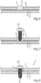
- a flow hole 9 is melted through the press-in element 5, the steel component 2 and the component 7 by means of a flow drilling element, in this case a flow hole screw 10. The melting takes place due to friction and a resulting temperature increase in the area around the flow hole screw 10.
- the flow hole screw 10 to create the flow hole 9 is placed on the press-in element 5 and first moved through it. The flow hole 9 is then melted through the adhesive 8 and the component 7.
- the press-in element 5 melts as a result of the generation of heat during the creation of the flow hole 9 and thereby changes its shape.
- Fig. 8 shows how the press-in element 5 melts into a layer formed by the adhesive 8 and thus shields or seals the adhesive 8 from the flow hole screw 10.
- the flow hole screw 10 can remain arranged in the flow hole 9 or, after the adhesive 8 and the press-in element 5 melted as a result of the heat development, can be removed from the flow hole 9 after the adhesive 8 has hardened.
- the method described is based on the knowledge that it is currently not possible to join press-hardened steel components by means of the flow hole screw 10 and an adhesive layer in between without the adhesive 8 affecting the area around the flow hole 9 on the press-hardened steel component 2 or on the press-hardened steel component 2 or on the Component 7 dirty.
- the press-in element 5 provides a remedy by sealing this area.
- the press-in element 5 should have a relatively low strength compared to the press-hardened steel component 2, which means that it is currently not possible to introduce the press-in element 5 into the steel component 2 without a through-hole.
- the problem is that the press-in element 5 is softer than the steel component 2, but is intended to pierce it. Since piercing or punching through the steel component 2 by means of the press-in element 5, which is softer than the steel component 2, is currently not possible without a through-hole, an additional process step, which is associated with additional costs, is required.
- the steel component composite 1 Similar to a closure of a beverage can or a SIM card, the predetermined breaking point 3 in the form of the opening 6 to be produced later is to be introduced during the manufacturing process of the steel component 2.
- This predetermined breaking point 3 is created as a trench-shaped depression in the steel component 2 through a contour on a tool half, which is pressed into a material of the steel component 2 during the manufacturing process of the press-hardened steel component 2.
- This indentation requires only little force, since the steel component 2 is almost doughy due to heating in the manufacturing process. There is no chip or waste that would have to be removed.
- the additional process step in which it For example, it would be a matter of laser cutting or punching before the press-in element 5 is introduced, can be saved.
Landscapes
- Engineering & Computer Science (AREA)
- Mechanical Engineering (AREA)
- Standing Axle, Rod, Or Tube Structures Coupled By Welding, Adhesion, Or Deposition (AREA)
- Connection Of Plates (AREA)
Claims (8)
- Procédé de production d'un composite de composant en acier (1), procédé dans lequel- un composant en acier (2) est pourvu d'un point de rupture (3),- le point de rupture (3) du composant en acier (2) est perforé au moyen d'un élément d'enfoncement (5) pour former une ouverture (6),- l'élément d'enfoncement (5) est enfoncé dans l'ouverture (6) du composant en acier (2),- un composant (7) est collé sur le composant en acier (2) au moyen d'un adhésif (8) appliqué de manière sensiblement bidimensionnelle au moins par chevauchement avec l'élément d'enfoncement (5), et- un trou d'écoulement (9) est ménagé par fusion à travers l'élément d'enfoncement (5), le composant en acier (2) et le composant (7) au moyen d'un élément de perçage par écoulement (10).
- Procédé selon la revendication 1,
caractérisé en ce que
le composant en acier (2) est pourvu du point de rupture (3) pendant le durcissement. - Procédé selon la revendication 1 ou 2,
caractérisé en ce que
le trou d'écoulement (9) est ménagé pendant un processus de durcissement de l'adhésif (8) au moyen de l'élément de perçage par écoulement (10). - Procédé selon l'une des revendications précédentes,
caractérisé en ce que
le composant (7) utilisé est un cadre en aluminium qui est collé au composant en acier (2) par chevauchement avec l'élément d'enfoncement (5). - Procédé selon l'une des revendications précédentes,
caractérisé en ce que
le point de rupture (3) est réalisé par une perforation ménagée dans le composant en acier (2). - Procédé selon l'une des revendications 1 à 4,
caractérisé en ce que
le point de rupture (3) est réalisé par un rétrécissement de matière local (4) du composant en acier (2) au moyen d'un élément de moulage. - Composite de composant en acier (1), comprenant un composant en acier (2), qui comporte une ouverture (6) ménagée par un élément d'enfoncement (5) par perforation d'un point de rupture (3), l'élément d'enfoncement (5) qui est enfoncé dans l'ouverture (6) du composant en acier (2), un composant (7) qui est fixé au composant en acier (2) au moyen d'un adhésif (8) au moins pour un chevauchement avec l'élément d'enfoncement (5),
le composite de composant en acier (1) comportant un trou d'écoulement (9) qui s'étend à travers l'élément d'enfoncement (5), le composant en acier (2) et le composant (7) par chevauchement. - Composant en acier composite (1) selon la revendication 7,
caractérisé en ce que
une vis de trou d'écoulement (10) est disposée dans le trou d'écoulement (9), laquelle permet de réaliser le trou d'écoulement (9).
Applications Claiming Priority (2)
| Application Number | Priority Date | Filing Date | Title |
|---|---|---|---|
| DE102017210864.9A DE102017210864B4 (de) | 2017-06-28 | 2017-06-28 | Verfahren zur Herstellung eines Stahlbauteilverbunds sowie Stahlbauteilverbund |
| PCT/EP2018/062744 WO2019001839A1 (fr) | 2017-06-28 | 2018-05-16 | Procédé de fabrication d'une pièce composite en acier ainsi que pièce composite en acier |
Publications (2)
| Publication Number | Publication Date |
|---|---|
| EP3645189A1 EP3645189A1 (fr) | 2020-05-06 |
| EP3645189B1 true EP3645189B1 (fr) | 2021-07-07 |
Family
ID=62196577
Family Applications (1)
| Application Number | Title | Priority Date | Filing Date |
|---|---|---|---|
| EP18725490.9A Active EP3645189B1 (fr) | 2017-06-28 | 2018-05-16 | Procédé de fabrication d'une pièce composite en acier ainsi que pièce composite en acier |
Country Status (5)
| Country | Link |
|---|---|
| US (1) | US11203050B2 (fr) |
| EP (1) | EP3645189B1 (fr) |
| CN (1) | CN110475629B (fr) |
| DE (1) | DE102017210864B4 (fr) |
| WO (1) | WO2019001839A1 (fr) |
Families Citing this family (2)
| Publication number | Priority date | Publication date | Assignee | Title |
|---|---|---|---|---|
| DE102020104473A1 (de) * | 2020-02-20 | 2021-08-26 | Bayerische Motoren Werke Aktiengesellschaft | Verfahren zum Bereitstellen eines Bauteilverbunds für ein Kraftfahrzeug sowie Bauteilverbund für ein Kraftfahrzeug |
| CN115042271A (zh) * | 2022-06-06 | 2022-09-13 | 哈尔滨工业大学 | 一种热塑性聚合物复合材料的孔壁补偿摩擦钻方法 |
Family Cites Families (15)
| Publication number | Priority date | Publication date | Assignee | Title |
|---|---|---|---|---|
| DE102005041350A1 (de) * | 2005-08-31 | 2007-03-01 | Ejot Gmbh & Co. Kg | Mit einem Loch einer Platte fluchtendes Mutterteil für ein Befestigungsmittel |
| JP2009285678A (ja) * | 2008-05-28 | 2009-12-10 | Kobe Steel Ltd | 鋼材と軽合金材との異材接合方法および異材接合体、鋼材との異材接合用軽合金材、鋼材と軽合金材との異材接合用リベット。 |
| DE102009039817A1 (de) * | 2009-09-02 | 2011-03-03 | Profil Verbindungstechnik Gmbh & Co. Kg | Selbststanzendes Mutterelement und Zusammenbauteil bestehend aus dem Mutterelement und einem Blechteil |
| DE102009042336A1 (de) | 2009-09-21 | 2011-03-24 | Profil Verbindungstechnik Gmbh & Co. Kg | Selbststanzendes hohles Einpresselement, Zusammenbauteil bestehend aus einem Einpresselement und einem Blechteil sowie ein Verfahren zur Herstellung einer selbststanzenden Einpressmutter sowie zur Anbringung einer selbststanzenden Einpressmutter |
| DE102010063717A1 (de) * | 2010-12-21 | 2012-06-21 | Bayerische Motoren Werke Aktiengesellschaft | Verfahren zum Verbinden mindestens zweier Bauteile gemäß dem Oberbegriff des Patentanspruches 1 |
| DE102011018748B3 (de) * | 2011-04-27 | 2012-07-26 | Audi Ag | Verfahren zum Herstellen von Anschlussbuchsen und zugehöriges Bauteil |
| DE102011114801A1 (de) * | 2011-10-01 | 2012-05-03 | Daimler Ag | Verfahren zum Verbinden von flächigen Fügepartnern sowie Verbindungsbereich von flächigen Fügepartnern |
| US20130273312A1 (en) * | 2012-04-17 | 2013-10-17 | Ford Global Technologies, Llc | Method of Fastening Parts to a Composite Part |
| DE102012222640A1 (de) * | 2012-12-10 | 2014-06-12 | Bayerische Motoren Werke Aktiengesellschaft | Schraubverbund |
| DE102013103719B4 (de) * | 2012-12-19 | 2024-04-18 | Dr. Ing. H.C. F. Porsche Aktiengesellschaft | Tragstruktur eines Kraftfahrzeuges und Verwendung einer Tragstruktur |
| JP6161198B2 (ja) * | 2013-08-29 | 2017-07-12 | 株式会社Subaru | 異材接合方法 |
| DE102014204292A1 (de) * | 2014-03-10 | 2015-09-10 | Bayerische Motoren Werke Aktiengesellschaft | Verfahren zum Herstellen einer Schraub-Klebverbindung unter Verwendung einer fließlochformenden Schraube, sowie hiernach hergestellter Bauteilverbund |
| DE102014226542A1 (de) | 2014-12-19 | 2016-06-23 | Bayerische Motoren Werke Aktiengesellschaft | Pressgehärtetes Blechbauteil mit wenigstens einer Sollbruchstelle, sowie Bauteilverbund und Kraftfahrzeugkarosserie mit solchem Blechbauteil |
| DE102015214149A1 (de) * | 2015-07-27 | 2017-02-02 | Bayerische Motoren Werke Aktiengesellschaft | Verfahren zur Herstellung eines Bauteilverbunds durch indirektes Fügen mittels eingepresstem Blechbutzen, sowie hiermit hergestellter Bauteilverbund und Kraftfahrzeugkarosserie mit solchem Bauteilverbund |
| US9695853B2 (en) | 2015-11-11 | 2017-07-04 | Ford Global Technologies, Llc | High energy absorption joint |
-
2017
- 2017-06-28 DE DE102017210864.9A patent/DE102017210864B4/de active Active
-
2018
- 2018-05-16 EP EP18725490.9A patent/EP3645189B1/fr active Active
- 2018-05-16 WO PCT/EP2018/062744 patent/WO2019001839A1/fr not_active Ceased
- 2018-05-16 CN CN201880021810.1A patent/CN110475629B/zh active Active
-
2019
- 2019-11-22 US US16/691,832 patent/US11203050B2/en active Active
Also Published As
| Publication number | Publication date |
|---|---|
| CN110475629B (zh) | 2021-02-26 |
| CN110475629A (zh) | 2019-11-19 |
| DE102017210864B4 (de) | 2025-07-17 |
| US20200086374A1 (en) | 2020-03-19 |
| EP3645189A1 (fr) | 2020-05-06 |
| DE102017210864A1 (de) | 2019-01-03 |
| WO2019001839A1 (fr) | 2019-01-03 |
| US11203050B2 (en) | 2021-12-21 |
Similar Documents
| Publication | Publication Date | Title |
|---|---|---|
| DE102012008798B4 (de) | Verfahren zum Fügen sowie Verbindungselement | |
| DE102012013325A1 (de) | Fügen von Bauelementen aus unterschiedlichen Werkstoffen mittels eines Fügehilfsmittels | |
| WO2013076117A1 (fr) | Procédé de fabrication d'une pièce en tôle composite comportant une zone métallique et outil de formage correspondant | |
| EP2554290A1 (fr) | Procédé de liaison d'une pièce formée à chaud avec une autre pièce de matière quelconque | |
| DE102011114306A1 (de) | Verfahren zum Fügen von wenigstens zwei FVK-Bauteilen | |
| DE102012109046A1 (de) | Verfahren und Vorrichtung zur Herstellung einer Öffnung in ein Leichtblech | |
| EP3648911B1 (fr) | Procédé de fabrication d'une plaque de refroidissement | |
| EP3645189B1 (fr) | Procédé de fabrication d'une pièce composite en acier ainsi que pièce composite en acier | |
| DE102016001401A1 (de) | Verfahren und Vorrichtung zum Herstellen von Verbindungsbereichen an Faser-Matrix-Verbund-Bauteilen | |
| EP2638988B1 (fr) | Système comprenant un rivet auto-poinçonneur et des pièces à assembler, et procédé d'assemblage desdites pièces avec ledit rivet | |
| DE102007055856A1 (de) | Nietschweißverfahren | |
| DE102008000517B4 (de) | Verfahren zum druckdichten Fügen eines metallischen Lenkgetriebegehäuses mit einem Kunststoffgehäusedeckel | |
| DE102010044902B4 (de) | Verfahren zum Einbringen einer Gewindehülse in ein Werkstück und Fügeverbindung zwischen Gewindehülse und Werkstück | |
| DE102014003181B4 (de) | Verfahren zum Verbinden von wenigstens zwei Bauteilen sowie Verbindungsanordnung | |
| EP3906124B1 (fr) | Procédé de fabrication d'une plaque de refroidissement | |
| DE102015210963A1 (de) | Thermoplastischer Reibverbinder | |
| DE102014009637A1 (de) | Befestigungselement zur Herstellung einer Klebeverbindung mit einer Montagefläche eines Fahrzeugbauteils sowie Verfahren zum Fügen des Befestigungselementes mit der Montagefläche | |
| DE102016200357B4 (de) | Verfahren zum Fügen von mindestens zwei Bauteilen mittels eines gehärteten Fügeelements | |
| DE102014217075A1 (de) | Verfahren zum Herstellen einer Temperiervorrichtung und Temperiervorrichtung | |
| DE102010031709A1 (de) | Verfahren zum Fügen von Bauteilen mittels Widerstandsschweißen sowie Fügeteil hierfür | |
| DE102013110761A1 (de) | Verfahren zum Herstellen eines metallischen Verbundbauteils und metallisches Verbundbauteil | |
| DE102015209531B4 (de) | Verfahren zum Herstellen einer Bauteilverbindung | |
| DE102022131477A1 (de) | Verfahren zur Applikation eines pastösen Materials sowie Fahrzeug | |
| DE102009014192A1 (de) | Karosseriebauteil und Verfahren zu dessen Herstellung | |
| DE102013210590A1 (de) | Verfahren zum Verbinden eines faserhaltigen Bauteils mit einem metallischen Bauteil und Bauteilverbund |
Legal Events
| Date | Code | Title | Description |
|---|---|---|---|
| STAA | Information on the status of an ep patent application or granted ep patent |
Free format text: STATUS: UNKNOWN |
|
| STAA | Information on the status of an ep patent application or granted ep patent |
Free format text: STATUS: THE INTERNATIONAL PUBLICATION HAS BEEN MADE |
|
| PUAI | Public reference made under article 153(3) epc to a published international application that has entered the european phase |
Free format text: ORIGINAL CODE: 0009012 |
|
| STAA | Information on the status of an ep patent application or granted ep patent |
Free format text: STATUS: REQUEST FOR EXAMINATION WAS MADE |
|
| 17P | Request for examination filed |
Effective date: 20191217 |
|
| AK | Designated contracting states |
Kind code of ref document: A1 Designated state(s): AL AT BE BG CH CY CZ DE DK EE ES FI FR GB GR HR HU IE IS IT LI LT LU LV MC MK MT NL NO PL PT RO RS SE SI SK SM TR |
|
| AX | Request for extension of the european patent |
Extension state: BA ME |
|
| DAV | Request for validation of the european patent (deleted) | ||
| DAX | Request for extension of the european patent (deleted) | ||
| GRAP | Despatch of communication of intention to grant a patent |
Free format text: ORIGINAL CODE: EPIDOSNIGR1 |
|
| STAA | Information on the status of an ep patent application or granted ep patent |
Free format text: STATUS: GRANT OF PATENT IS INTENDED |
|
| INTG | Intention to grant announced |
Effective date: 20210204 |
|
| GRAS | Grant fee paid |
Free format text: ORIGINAL CODE: EPIDOSNIGR3 |
|
| GRAA | (expected) grant |
Free format text: ORIGINAL CODE: 0009210 |
|
| STAA | Information on the status of an ep patent application or granted ep patent |
Free format text: STATUS: THE PATENT HAS BEEN GRANTED |
|
| AK | Designated contracting states |
Kind code of ref document: B1 Designated state(s): AL AT BE BG CH CY CZ DE DK EE ES FI FR GB GR HR HU IE IS IT LI LT LU LV MC MK MT NL NO PL PT RO RS SE SI SK SM TR |
|
| REG | Reference to a national code |
Ref country code: GB Ref legal event code: FG4D Free format text: NOT ENGLISH |
|
| REG | Reference to a national code |
Ref country code: AT Ref legal event code: REF Ref document number: 1408066 Country of ref document: AT Kind code of ref document: T Effective date: 20210715 |
|
| REG | Reference to a national code |
Ref country code: DE Ref legal event code: R096 Ref document number: 502018006033 Country of ref document: DE |
|
| REG | Reference to a national code |
Ref country code: IE Ref legal event code: FG4D Free format text: LANGUAGE OF EP DOCUMENT: GERMAN |
|
| REG | Reference to a national code |
Ref country code: LT Ref legal event code: MG9D |
|
| REG | Reference to a national code |
Ref country code: NL Ref legal event code: MP Effective date: 20210707 |
|
| PG25 | Lapsed in a contracting state [announced via postgrant information from national office to epo] |
Ref country code: SE Free format text: LAPSE BECAUSE OF FAILURE TO SUBMIT A TRANSLATION OF THE DESCRIPTION OR TO PAY THE FEE WITHIN THE PRESCRIBED TIME-LIMIT Effective date: 20210707 Ref country code: RS Free format text: LAPSE BECAUSE OF FAILURE TO SUBMIT A TRANSLATION OF THE DESCRIPTION OR TO PAY THE FEE WITHIN THE PRESCRIBED TIME-LIMIT Effective date: 20210707 Ref country code: HR Free format text: LAPSE BECAUSE OF FAILURE TO SUBMIT A TRANSLATION OF THE DESCRIPTION OR TO PAY THE FEE WITHIN THE PRESCRIBED TIME-LIMIT Effective date: 20210707 Ref country code: ES Free format text: LAPSE BECAUSE OF FAILURE TO SUBMIT A TRANSLATION OF THE DESCRIPTION OR TO PAY THE FEE WITHIN THE PRESCRIBED TIME-LIMIT Effective date: 20210707 Ref country code: FI Free format text: LAPSE BECAUSE OF FAILURE TO SUBMIT A TRANSLATION OF THE DESCRIPTION OR TO PAY THE FEE WITHIN THE PRESCRIBED TIME-LIMIT Effective date: 20210707 Ref country code: NO Free format text: LAPSE BECAUSE OF FAILURE TO SUBMIT A TRANSLATION OF THE DESCRIPTION OR TO PAY THE FEE WITHIN THE PRESCRIBED TIME-LIMIT Effective date: 20211007 Ref country code: NL Free format text: LAPSE BECAUSE OF FAILURE TO SUBMIT A TRANSLATION OF THE DESCRIPTION OR TO PAY THE FEE WITHIN THE PRESCRIBED TIME-LIMIT Effective date: 20210707 Ref country code: PT Free format text: LAPSE BECAUSE OF FAILURE TO SUBMIT A TRANSLATION OF THE DESCRIPTION OR TO PAY THE FEE WITHIN THE PRESCRIBED TIME-LIMIT Effective date: 20211108 Ref country code: BG Free format text: LAPSE BECAUSE OF FAILURE TO SUBMIT A TRANSLATION OF THE DESCRIPTION OR TO PAY THE FEE WITHIN THE PRESCRIBED TIME-LIMIT Effective date: 20211007 Ref country code: LT Free format text: LAPSE BECAUSE OF FAILURE TO SUBMIT A TRANSLATION OF THE DESCRIPTION OR TO PAY THE FEE WITHIN THE PRESCRIBED TIME-LIMIT Effective date: 20210707 |
|
| PG25 | Lapsed in a contracting state [announced via postgrant information from national office to epo] |
Ref country code: PL Free format text: LAPSE BECAUSE OF FAILURE TO SUBMIT A TRANSLATION OF THE DESCRIPTION OR TO PAY THE FEE WITHIN THE PRESCRIBED TIME-LIMIT Effective date: 20210707 Ref country code: LV Free format text: LAPSE BECAUSE OF FAILURE TO SUBMIT A TRANSLATION OF THE DESCRIPTION OR TO PAY THE FEE WITHIN THE PRESCRIBED TIME-LIMIT Effective date: 20210707 Ref country code: GR Free format text: LAPSE BECAUSE OF FAILURE TO SUBMIT A TRANSLATION OF THE DESCRIPTION OR TO PAY THE FEE WITHIN THE PRESCRIBED TIME-LIMIT Effective date: 20211008 |
|
| REG | Reference to a national code |
Ref country code: DE Ref legal event code: R097 Ref document number: 502018006033 Country of ref document: DE |
|
| PG25 | Lapsed in a contracting state [announced via postgrant information from national office to epo] |
Ref country code: DK Free format text: LAPSE BECAUSE OF FAILURE TO SUBMIT A TRANSLATION OF THE DESCRIPTION OR TO PAY THE FEE WITHIN THE PRESCRIBED TIME-LIMIT Effective date: 20210707 |
|
| PLBE | No opposition filed within time limit |
Free format text: ORIGINAL CODE: 0009261 |
|
| STAA | Information on the status of an ep patent application or granted ep patent |
Free format text: STATUS: NO OPPOSITION FILED WITHIN TIME LIMIT |
|
| PG25 | Lapsed in a contracting state [announced via postgrant information from national office to epo] |
Ref country code: SM Free format text: LAPSE BECAUSE OF FAILURE TO SUBMIT A TRANSLATION OF THE DESCRIPTION OR TO PAY THE FEE WITHIN THE PRESCRIBED TIME-LIMIT Effective date: 20210707 Ref country code: SK Free format text: LAPSE BECAUSE OF FAILURE TO SUBMIT A TRANSLATION OF THE DESCRIPTION OR TO PAY THE FEE WITHIN THE PRESCRIBED TIME-LIMIT Effective date: 20210707 Ref country code: RO Free format text: LAPSE BECAUSE OF FAILURE TO SUBMIT A TRANSLATION OF THE DESCRIPTION OR TO PAY THE FEE WITHIN THE PRESCRIBED TIME-LIMIT Effective date: 20210707 Ref country code: EE Free format text: LAPSE BECAUSE OF FAILURE TO SUBMIT A TRANSLATION OF THE DESCRIPTION OR TO PAY THE FEE WITHIN THE PRESCRIBED TIME-LIMIT Effective date: 20210707 Ref country code: CZ Free format text: LAPSE BECAUSE OF FAILURE TO SUBMIT A TRANSLATION OF THE DESCRIPTION OR TO PAY THE FEE WITHIN THE PRESCRIBED TIME-LIMIT Effective date: 20210707 Ref country code: AL Free format text: LAPSE BECAUSE OF FAILURE TO SUBMIT A TRANSLATION OF THE DESCRIPTION OR TO PAY THE FEE WITHIN THE PRESCRIBED TIME-LIMIT Effective date: 20210707 |
|
| 26N | No opposition filed |
Effective date: 20220408 |
|
| PG25 | Lapsed in a contracting state [announced via postgrant information from national office to epo] |
Ref country code: IT Free format text: LAPSE BECAUSE OF FAILURE TO SUBMIT A TRANSLATION OF THE DESCRIPTION OR TO PAY THE FEE WITHIN THE PRESCRIBED TIME-LIMIT Effective date: 20210707 |
|
| REG | Reference to a national code |
Ref country code: CH Ref legal event code: PL |
|
| REG | Reference to a national code |
Ref country code: BE Ref legal event code: MM Effective date: 20220531 |
|
| PG25 | Lapsed in a contracting state [announced via postgrant information from national office to epo] |
Ref country code: MC Free format text: LAPSE BECAUSE OF FAILURE TO SUBMIT A TRANSLATION OF THE DESCRIPTION OR TO PAY THE FEE WITHIN THE PRESCRIBED TIME-LIMIT Effective date: 20210707 Ref country code: LU Free format text: LAPSE BECAUSE OF NON-PAYMENT OF DUE FEES Effective date: 20220516 Ref country code: LI Free format text: LAPSE BECAUSE OF NON-PAYMENT OF DUE FEES Effective date: 20220531 Ref country code: CH Free format text: LAPSE BECAUSE OF NON-PAYMENT OF DUE FEES Effective date: 20220531 |
|
| PG25 | Lapsed in a contracting state [announced via postgrant information from national office to epo] |
Ref country code: IE Free format text: LAPSE BECAUSE OF NON-PAYMENT OF DUE FEES Effective date: 20220516 |
|
| PG25 | Lapsed in a contracting state [announced via postgrant information from national office to epo] |
Ref country code: BE Free format text: LAPSE BECAUSE OF NON-PAYMENT OF DUE FEES Effective date: 20220531 |
|
| P01 | Opt-out of the competence of the unified patent court (upc) registered |
Effective date: 20230503 |
|
| PG25 | Lapsed in a contracting state [announced via postgrant information from national office to epo] |
Ref country code: MK Free format text: LAPSE BECAUSE OF FAILURE TO SUBMIT A TRANSLATION OF THE DESCRIPTION OR TO PAY THE FEE WITHIN THE PRESCRIBED TIME-LIMIT Effective date: 20210707 Ref country code: CY Free format text: LAPSE BECAUSE OF FAILURE TO SUBMIT A TRANSLATION OF THE DESCRIPTION OR TO PAY THE FEE WITHIN THE PRESCRIBED TIME-LIMIT Effective date: 20210707 |
|
| PG25 | Lapsed in a contracting state [announced via postgrant information from national office to epo] |
Ref country code: HU Free format text: LAPSE BECAUSE OF FAILURE TO SUBMIT A TRANSLATION OF THE DESCRIPTION OR TO PAY THE FEE WITHIN THE PRESCRIBED TIME-LIMIT; INVALID AB INITIO Effective date: 20180516 |
|
| REG | Reference to a national code |
Ref country code: AT Ref legal event code: MM01 Ref document number: 1408066 Country of ref document: AT Kind code of ref document: T Effective date: 20230516 |
|
| PG25 | Lapsed in a contracting state [announced via postgrant information from national office to epo] |
Ref country code: AT Free format text: LAPSE BECAUSE OF NON-PAYMENT OF DUE FEES Effective date: 20230516 |
|
| PG25 | Lapsed in a contracting state [announced via postgrant information from national office to epo] |
Ref country code: AT Free format text: LAPSE BECAUSE OF NON-PAYMENT OF DUE FEES Effective date: 20230516 |
|
| PG25 | Lapsed in a contracting state [announced via postgrant information from national office to epo] |
Ref country code: MT Free format text: LAPSE BECAUSE OF FAILURE TO SUBMIT A TRANSLATION OF THE DESCRIPTION OR TO PAY THE FEE WITHIN THE PRESCRIBED TIME-LIMIT Effective date: 20210707 |
|
| PGFP | Annual fee paid to national office [announced via postgrant information from national office to epo] |
Ref country code: DE Payment date: 20250512 Year of fee payment: 8 |
|
| PGFP | Annual fee paid to national office [announced via postgrant information from national office to epo] |
Ref country code: GB Payment date: 20250522 Year of fee payment: 8 |
|
| PGFP | Annual fee paid to national office [announced via postgrant information from national office to epo] |
Ref country code: FR Payment date: 20250521 Year of fee payment: 8 |
|
| PG25 | Lapsed in a contracting state [announced via postgrant information from national office to epo] |
Ref country code: TR Free format text: LAPSE BECAUSE OF FAILURE TO SUBMIT A TRANSLATION OF THE DESCRIPTION OR TO PAY THE FEE WITHIN THE PRESCRIBED TIME-LIMIT Effective date: 20210707 |
|
| PGFP | Annual fee paid to national office [announced via postgrant information from national office to epo] |
Ref country code: AT Payment date: 20260410 Year of fee payment: 5 |