EP3645236B1 - Extrusionskopf mit kanälen zur herstellung von einsätzen in einem profilband zur herstellung eines luftreifens und entsprechendes extrusionsverfahren - Google Patents
Extrusionskopf mit kanälen zur herstellung von einsätzen in einem profilband zur herstellung eines luftreifens und entsprechendes extrusionsverfahren Download PDFInfo
- Publication number
- EP3645236B1 EP3645236B1 EP18762351.7A EP18762351A EP3645236B1 EP 3645236 B1 EP3645236 B1 EP 3645236B1 EP 18762351 A EP18762351 A EP 18762351A EP 3645236 B1 EP3645236 B1 EP 3645236B1
- Authority
- EP
- European Patent Office
- Prior art keywords
- downstream
- upstream
- extrusion
- channel
- insert
- Prior art date
- Legal status (The legal status is an assumption and is not a legal conclusion. Google has not performed a legal analysis and makes no representation as to the accuracy of the status listed.)
- Active
Links
Images


Classifications
-
- B—PERFORMING OPERATIONS; TRANSPORTING
- B29—WORKING OF PLASTICS; WORKING OF SUBSTANCES IN A PLASTIC STATE IN GENERAL
- B29C—SHAPING OR JOINING OF PLASTICS; SHAPING OF MATERIAL IN A PLASTIC STATE, NOT OTHERWISE PROVIDED FOR; AFTER-TREATMENT OF THE SHAPED PRODUCTS, e.g. REPAIRING
- B29C48/00—Extrusion moulding, i.e. expressing the moulding material through a die or nozzle which imparts the desired form; Apparatus therefor
- B29C48/03—Extrusion moulding, i.e. expressing the moulding material through a die or nozzle which imparts the desired form; Apparatus therefor characterised by the shape of the extruded material at extrusion
- B29C48/12—Articles with an irregular circumference when viewed in cross-section, e.g. window profiles
-
- B—PERFORMING OPERATIONS; TRANSPORTING
- B29—WORKING OF PLASTICS; WORKING OF SUBSTANCES IN A PLASTIC STATE IN GENERAL
- B29C—SHAPING OR JOINING OF PLASTICS; SHAPING OF MATERIAL IN A PLASTIC STATE, NOT OTHERWISE PROVIDED FOR; AFTER-TREATMENT OF THE SHAPED PRODUCTS, e.g. REPAIRING
- B29C48/00—Extrusion moulding, i.e. expressing the moulding material through a die or nozzle which imparts the desired form; Apparatus therefor
- B29C48/025—General arrangement or layout of plant
-
- B—PERFORMING OPERATIONS; TRANSPORTING
- B29—WORKING OF PLASTICS; WORKING OF SUBSTANCES IN A PLASTIC STATE IN GENERAL
- B29C—SHAPING OR JOINING OF PLASTICS; SHAPING OF MATERIAL IN A PLASTIC STATE, NOT OTHERWISE PROVIDED FOR; AFTER-TREATMENT OF THE SHAPED PRODUCTS, e.g. REPAIRING
- B29C48/00—Extrusion moulding, i.e. expressing the moulding material through a die or nozzle which imparts the desired form; Apparatus therefor
- B29C48/03—Extrusion moulding, i.e. expressing the moulding material through a die or nozzle which imparts the desired form; Apparatus therefor characterised by the shape of the extruded material at extrusion
- B29C48/13—Articles with a cross-section varying in the longitudinal direction, e.g. corrugated pipes
-
- B—PERFORMING OPERATIONS; TRANSPORTING
- B29—WORKING OF PLASTICS; WORKING OF SUBSTANCES IN A PLASTIC STATE IN GENERAL
- B29C—SHAPING OR JOINING OF PLASTICS; SHAPING OF MATERIAL IN A PLASTIC STATE, NOT OTHERWISE PROVIDED FOR; AFTER-TREATMENT OF THE SHAPED PRODUCTS, e.g. REPAIRING
- B29C48/00—Extrusion moulding, i.e. expressing the moulding material through a die or nozzle which imparts the desired form; Apparatus therefor
- B29C48/16—Articles comprising two or more components, e.g. co-extruded layers
- B29C48/18—Articles comprising two or more components, e.g. co-extruded layers the components being layers
- B29C48/21—Articles comprising two or more components, e.g. co-extruded layers the components being layers the layers being joined at their surfaces
-
- B—PERFORMING OPERATIONS; TRANSPORTING
- B29—WORKING OF PLASTICS; WORKING OF SUBSTANCES IN A PLASTIC STATE IN GENERAL
- B29C—SHAPING OR JOINING OF PLASTICS; SHAPING OF MATERIAL IN A PLASTIC STATE, NOT OTHERWISE PROVIDED FOR; AFTER-TREATMENT OF THE SHAPED PRODUCTS, e.g. REPAIRING
- B29C48/00—Extrusion moulding, i.e. expressing the moulding material through a die or nozzle which imparts the desired form; Apparatus therefor
- B29C48/25—Component parts, details or accessories; Auxiliary operations
- B29C48/30—Extrusion nozzles or dies
- B29C48/305—Extrusion nozzles or dies having a wide opening, e.g. for forming sheets
- B29C48/307—Extrusion nozzles or dies having a wide opening, e.g. for forming sheets specially adapted for bringing together components, e.g. melts within the die
-
- B—PERFORMING OPERATIONS; TRANSPORTING
- B29—WORKING OF PLASTICS; WORKING OF SUBSTANCES IN A PLASTIC STATE IN GENERAL
- B29C—SHAPING OR JOINING OF PLASTICS; SHAPING OF MATERIAL IN A PLASTIC STATE, NOT OTHERWISE PROVIDED FOR; AFTER-TREATMENT OF THE SHAPED PRODUCTS, e.g. REPAIRING
- B29C48/00—Extrusion moulding, i.e. expressing the moulding material through a die or nozzle which imparts the desired form; Apparatus therefor
- B29C48/25—Component parts, details or accessories; Auxiliary operations
- B29C48/30—Extrusion nozzles or dies
- B29C48/35—Extrusion nozzles or dies with rollers
-
- B—PERFORMING OPERATIONS; TRANSPORTING
- B29—WORKING OF PLASTICS; WORKING OF SUBSTANCES IN A PLASTIC STATE IN GENERAL
- B29C—SHAPING OR JOINING OF PLASTICS; SHAPING OF MATERIAL IN A PLASTIC STATE, NOT OTHERWISE PROVIDED FOR; AFTER-TREATMENT OF THE SHAPED PRODUCTS, e.g. REPAIRING
- B29C48/00—Extrusion moulding, i.e. expressing the moulding material through a die or nozzle which imparts the desired form; Apparatus therefor
- B29C48/25—Component parts, details or accessories; Auxiliary operations
- B29C48/36—Means for plasticising or homogenising the moulding material or forcing it through the nozzle or die
- B29C48/49—Means for plasticising or homogenising the moulding material or forcing it through the nozzle or die using two or more extruders to feed one die or nozzle
-
- B—PERFORMING OPERATIONS; TRANSPORTING
- B29—WORKING OF PLASTICS; WORKING OF SUBSTANCES IN A PLASTIC STATE IN GENERAL
- B29D—PRODUCING PARTICULAR ARTICLES FROM PLASTICS OR FROM SUBSTANCES IN A PLASTIC STATE
- B29D30/00—Producing pneumatic or solid tyres or parts thereof
- B29D30/06—Pneumatic tyres or parts thereof (e.g. produced by casting, moulding, compression moulding, injection moulding, centrifugal casting)
-
- B—PERFORMING OPERATIONS; TRANSPORTING
- B29—WORKING OF PLASTICS; WORKING OF SUBSTANCES IN A PLASTIC STATE IN GENERAL
- B29C—SHAPING OR JOINING OF PLASTICS; SHAPING OF MATERIAL IN A PLASTIC STATE, NOT OTHERWISE PROVIDED FOR; AFTER-TREATMENT OF THE SHAPED PRODUCTS, e.g. REPAIRING
- B29C48/00—Extrusion moulding, i.e. expressing the moulding material through a die or nozzle which imparts the desired form; Apparatus therefor
- B29C48/03—Extrusion moulding, i.e. expressing the moulding material through a die or nozzle which imparts the desired form; Apparatus therefor characterised by the shape of the extruded material at extrusion
- B29C48/07—Flat, e.g. panels
-
- B—PERFORMING OPERATIONS; TRANSPORTING
- B29—WORKING OF PLASTICS; WORKING OF SUBSTANCES IN A PLASTIC STATE IN GENERAL
- B29K—INDEXING SCHEME ASSOCIATED WITH SUBCLASSES B29B, B29C OR B29D, RELATING TO MOULDING MATERIALS OR TO MATERIALS FOR MOULDS, REINFORCEMENTS, FILLERS OR PREFORMED PARTS, e.g. INSERTS
- B29K2007/00—Use of natural rubber as moulding material
-
- B—PERFORMING OPERATIONS; TRANSPORTING
- B29—WORKING OF PLASTICS; WORKING OF SUBSTANCES IN A PLASTIC STATE IN GENERAL
- B29K—INDEXING SCHEME ASSOCIATED WITH SUBCLASSES B29B, B29C OR B29D, RELATING TO MOULDING MATERIALS OR TO MATERIALS FOR MOULDS, REINFORCEMENTS, FILLERS OR PREFORMED PARTS, e.g. INSERTS
- B29K2021/00—Use of unspecified rubbers as moulding material
-
- B—PERFORMING OPERATIONS; TRANSPORTING
- B29—WORKING OF PLASTICS; WORKING OF SUBSTANCES IN A PLASTIC STATE IN GENERAL
- B29K—INDEXING SCHEME ASSOCIATED WITH SUBCLASSES B29B, B29C OR B29D, RELATING TO MOULDING MATERIALS OR TO MATERIALS FOR MOULDS, REINFORCEMENTS, FILLERS OR PREFORMED PARTS, e.g. INSERTS
- B29K2105/00—Condition, form or state of moulded material or of the material to be shaped
- B29K2105/24—Condition, form or state of moulded material or of the material to be shaped crosslinked or vulcanised
- B29K2105/246—Uncured, e.g. green
-
- B—PERFORMING OPERATIONS; TRANSPORTING
- B29—WORKING OF PLASTICS; WORKING OF SUBSTANCES IN A PLASTIC STATE IN GENERAL
- B29L—INDEXING SCHEME ASSOCIATED WITH SUBCLASS B29C, RELATING TO PARTICULAR ARTICLES
- B29L2030/00—Pneumatic or solid tyres or parts thereof
- B29L2030/002—Treads
Definitions
- the invention lies in the field of the extrusion of a continuous profiled strip of a rubber-based material intended in particular for the manufacture of tires.
- the invention relates to the extrusion of complex profiles composed of the assembly of several profiles made from unvulcanized rubber mixtures of different compositions.
- These complex profiles are produced in a known manner using a coextrusion machine using several extruders opening into a pressurizing vault, and comprising several profile air gaps arranged so that the profiling and the final jointing of the different profiles are operated by the same profiling blade.
- a first radially internal profile P1 formed of a mixture M1 constitutes the underlayer
- a second profile P2 formed of a mixture M2 foreshadows the tread intended to come into contact with the ground.
- Longitudinal grooves P20, prefiguring the longitudinal grooves of the tire, are placed between the longitudinal cords P21 in which the blocks forming the final tread pattern of the tire are molded.
- the torus-shaped tire blank is capped with a section of strip taken from a continuous strip obtained using the coextrusion machine.
- the publication EP1448355 describes a coextrusion machine comprising a roller and an extrusion head comprising at least two flow channels of a rubber mixture of sub-layer and of a rubber mixture of tread, said channels opening into an orifice of extrusion through which are forced the two rubber mixes of underlayer and tread.
- the extrusion head also comprises a micro-extruder of a third electrically conductive rubber mixture, provided at its end with a nozzle, passing through the two flow channels so that the third electrically conductive rubber mixture is inserted into the mixtures. rubbery underlayer and tread upstream of the extrusion orifice.
- the publication EP 0 925 903 describes a so-called flat nose coextrusion machine (without roller) comprising an extrusion head comprising a first passage for the extrusion of the tread and a second passage for the extrusion of the underlayer considered to be conductive of the tread. electricity.
- a third passage arranged as a bypass from the second passage, opens into a slotted opening arranged behind the extrusion orifice so as to form a narrow electrically conductive strip passing through the portion of the tread which is weakly conductive of electricity.
- the invention is also interested in the manufacture of complex profiles intended to form the tread of a tire and comprising one or more inserts.
- These treads of a new type which are described for example in the publications WO2016 / 202703 and WO 2017/109392 , include mooring elements intended to reinforce the structural blocks in the event of transverse stress on the tire.
- the anchoring elements can be formed from the same mixture or from a mixture different from that constituting the underlayer.
- the invention is also interested in the manufacture of complex profiles intended to form the tread of a tire, said profiles possibly comprising structures of small thickness which form inserts or edging gums and whose profile may be disturbed. in the absence of any particular implementation device.
- treads in which the walls of the longitudinal grooves are covered with an edge rubber of low thickness and of different composition from the composition of the mixture forming the tread.
- This arrangement makes it possible in particular to reduce the propagation of cuts linked to attacks or to the penetration of gravel.
- edge rubbers of the type of those described above it may prove necessary to have edge rubbers of the type of those described above to protect treads comprising inserts arranged near the edge of a groove.
- a process for the coextrusion of a complex profile consisting of the assembly of profiles formed from different rubber mixtures. in which, using a coextrusion machine comprising an upstream extruder and a downstream extruder opening into an extrusion cavity formed by the space between a lower wall of an extrusion head and a profiling wall arranged opposite the lower wall.
- This method is characterized in that a portion of the first rubber mixture, intended to form the insert, is circulated between the walls of a channel which extend in a longitudinal direction between the upstream profiling blade and the blade. profiling, from an upstream end of the channel which is located upstream of the connection of the flows of the first and second rubber mixes to a downstream end of said channel which is located downstream of said connection of the flows and upstream of the blade of downstream profiling, said channel walls together forming a concave surface open towards the interior of the extrusion cavity, and being arranged so that the portion of the first rubber mixture which enters the channel and which is intended to form the insert, when it progresses longitudinally in the channel, remains in continuity of material with the underlayer without being brought into contact with the second mixture, and that the jointing of one or more side walls of said insert with the second rubber mixture is then carried out in the downstream air gap defined by the downstream profiling blade and the profiling wall.
- the first mixture coming from the upstream extruder therefore enters under pressure in the channel and remains in continuity of material with the mixture forming the sublayer due to the opening of the concavity of the channel on the side of said sublayer disposed radially towards the bottom. 'interior in relation to the channel.
- the second mixture comes into contact with the radially outer surface of the first section in the longitudinal space located between the upstream profiling blade and the downstream profiling blade. And the union of these flows is likely to generate significant movements of material within the second mixture in radial or transverse directions, in particular when the first and the second mixture have different rheologies.
- the portion of the first mixture intended to form the insert is not in contact with the second mixture, so as to prevent the profile of the insert from being deformed by the second mixture.
- This process thus makes it possible to protect the profile of the insert, in the part of the vault formed by the lower wall and the wall of the roller located between the upstream air gap and the downstream air gap, from the effects linked to the jointing of the first profile P1 with the second mixture M2 and operating in the area between the two air gaps, creating turbulence linked to pressure variations.
- This method is also particularly well suited to producing a complex profile serving as a component for producing a tire and in particular the tread of this tire.
- the extrusion head is characterized in that it comprises at least one channel, formed by walls extending in the longitudinal direction between the upstream profiling blade and the downstream profiling blade, together forming a concave surface open towards inside the extrusion cavity and defining a duct open at its two longitudinal ends.
- This extrusion head can be characterized in that it comprises at least one channel, formed by walls which extend in the longitudinal direction between the upstream profiling blade and the downstream profiling blade, from an upstream end of the channel. which is located upstream of the connection zone of the flows of the first and second rubber mixtures to a downstream end of said channel which is located downstream of said flow connection zone and upstream of the downstream profiling blade, said walls of the channel together forming a concave surface open towards the interior of the extrusion cavity, and being arranged so that, on the one hand, a portion of the flow of the first rubber mixture, intended to form an insert in the profile complex, can penetrate into the channel and progress longitudinally in said channel without being brought into contact with the second rubber mixture, but while remaining in continuity of material with an underlayer of the first pr ofiled in the first rubber mixture, which will have been shaped in an upstream air gap defined by the upstream profiling blade, and that, on the other hand, a jointing of one or more side walls of said insert with the second mixture rubber is then carried out
- the invention can relate to an extrusion head of a complex profile consisting of the assembly of several profiles formed from separate rubber mixtures, is intended to be mounted on a coextrusion machine in which the profiles progress in an extrusion cavity in an extrusion direction from upstream to downstream by defining a longitudinal direction, said head comprising a lower wall partly delimiting said extrusion cavity and a downstream extrusion block comprising a downstream profiling strip arranged in a transverse direction to determine a transverse profile of the complex section formed from the assembly of all the sections, said strip downstream profiling comprising at least one projection intended to form a groove in the complex profile said extrusion head is ca Characterizing in that it comprises at least one additional extrusion channel placed at the outlet of an additional extruder and opening into an upstream part of the projection, said additional extrusion channel comprising a lower outlet opening and at least one opening side outlet, open at the edge respectively of a lower wall of
- the side gills of the annex extrusion channel form openings through which the mixture from the annex extruder is extruded to form an edge gum on the bottom of the groove and on at least one of the side walls of the groove.
- the thickness of this edge rubber can be adjusted by adjusting the position of the partitions supporting the walls defining the annex extrusion channel and by modifying the outlet section of the side vents.
- the particular arrangement of the annex extrusion channel which is arranged in the downstream profiling blade just upstream of the projection, makes it possible to prevent the profile of the edge rubber, the thickness of which is relatively small, from being altered during setting. in joint with the gums or with the profiles coming from the upstream side of the machine and the assembly of which in the air gap formed by the downstream profiling blade is intended to form the final complex profile.
- the edging rubber covering the side wall of the insert bordering the groove will be of the same composition as the second mixture constituting the structural blocks of the tread, which will advantageously make it possible to obtain a homogeneous composition of the tread. tread, and in particular walls which delimit said longitudinal groove and structural blocks of said tread, while retaining the benefit of transverse retention of the structural blocks provided by said insert.
- Such chemical homogeneity of the walls of the groove will in particular make it possible to easily integrate into said groove structures of flexible lamellae or baffle types, which are intended to slow the propagation in the groove of air noises associated with rolling without, however, hindering the movement. water flow on wet pavement; in fact, the walls of the groove being all of the same composition, it is advantageously possible to produce sets of strips which will each be fixed to a different wall of the groove without it being necessary to adapt the fixing method according to the composition of the groove. the affected wall.
- the extrusion head may comprise, alone or in combination with one and / or the other of the characteristics described above, a cutting blade.
- downstream profiling which comprises at least one protrusion to form a longitudinal groove in the complex profile, and a channel which is arranged so as to dispose the insert at the border of a lateral edge of said groove so that a side wall of said insert forms the edge of said groove
- the ancillary extrusion channel comprises outlet openings arranged at the edge of said projection, upstream of said projection, and forming one or more lateral outlet openings and a lower outlet opening, so to be able to deposit in the groove of the complex profile an edge rubber which comprises a bottom edge rubber of the groove deposited on the bottom of the groove by the lower outlet opening and at least one lateral border rubber deposited on the side wall rale of the insert by a lateral outlet opening.
- the profiling wall can be fixed or, alternatively, the lower wall of the extrusion head has a concave shape of cylindrical profile with a given axis extending transversely, and of which a circumferential direction merges with the direction.
- longitudinal defining the direction of progression of the profile in the extrusion cavity and the profiling wall is formed by the radially outer wall of a cylindrical roller, movable in rotation about an axis coincident with the axis of the lower wall.
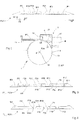
- the coextrusion machine shown in FIG. figure 2 comprises a cylindrical roller 10 driven in rotation about an axis 12 by a motor assembly (not shown).
- the generatrices of the roller extend in a transverse direction DT and form an extrusion wall defined here by the radially outer wall 11 of the roller 10.
- the extrusion head 2 comprises an upstream extrusion block 3 which is associated with an extruder 30 supplying a first mixture M1, and a downstream extrusion block 4 which is associated with a downstream extruder 40 supplying a second mixture M2.
- the invention applies to mixtures M1, M2 based on rubber, and in particular based on so-called “raw” rubber, that is to say unvulcanized, so that reference will preferably be made to to "rubber mixes" in the following.
- first and second mixtures M1, M2 and in particular to any mixtures of suitable polymers, optionally other than mixtures based on rubber.
- the radially inner bottom wall 20 of the extrusion head 2 has a generally cylindrical shape with axis 12 which is placed opposite the radially outer wall 11 of the roller 10.
- the space between the bottom wall and the radially outer wall of the roller forms a vault or else an extrusion cavity in which the pressurized mixture is shaped by passing through the air gaps, here an upstream air gap defined by the radially outer wall 11 of the roller 10 and by a blade upstream profiling 32 and, respectively, a downstream air gap defined by the radially outer wall 11 of the roller 10 and by a downstream profiling blade 42, said upstream 32 and downstream 42 profiling blades being an integral part of the extrusion head.
- the radial distance between the lower wall of the extrusion head 2 and the radially outer wall of the roller 10 at the level of the two transverse ends is of the order of a few tenths of a millimeter in order to limit the leaks of the rubber mixture.
- the roller 10 allows a better drive of the complex profile during extrusion in the longitudinal direction DL, and in particular makes it possible to reduce the edge effects at the level of the sole of the complex profile in contact with the radially outer wall 11 of the roller.
- the complex profile PC is directed in the longitudinal direction DL towards the downstream part of the extrusion machine on a belt 13.
- the direction of rotation R of the roller determines the direction of progression of the profile in the extrusion cavity of the machine, which is assimilated to the longitudinal direction DL.
- the radial direction DR therefore corresponds to a direction locally perpendicular to the transverse direction DT and to the longitudinal direction DL, and the direction radially directed towards the interior or radially internal corresponds to an orientation towards the interior of the extrusion cavity.
- the value of the distance between the first point and the second point in a direction perpendicular to the longitudinal direction and to the transverse direction and oriented in a direction going from the center of the cavity to the outside is positive.
- the figure 3 represents a first complex profile PC1 comprising a first profile P1 consisting of a first mixture M1 intended to form a first, radially internal layer, and a second profile P2 consisting of a second mixture M2 intended to form, radially on top of the first layer formed by the first profile P1, a tread.
- the profile of the tread comprises longitudinal grooves P20, prefiguring the grooves of the tire, said longitudinal grooves P20 being interposed between longitudinal cords P21 intended to form structural blocks of the tread.
- the longitudinal grooves P20 can be likened to the longitudinal grooves which said grooves foreshadow.
- the complex profile PC1 also comprises longitudinal inserts P10 which consist of the first mixture M1, which here have a generally triangular shape, and which rise in the radial direction DR from a fictitious base P13 situated on the radially outer face of a underlayer P14 produced in this same first mixture M1.
- said inserts P10 rise to the radially outer surface of the second section P2.
- the first profile P1 comprises on the one hand a first profile element which is intended to form a sub-layer P14, and on the other hand a second profile element (respectively several second profile elements) intended to form an insert P10 (respectively several inserts P10), although these elements, insert P10 and underlayer 14, are in practice preferably formed integrally. one with the other.
- These longitudinal inserts P10 are arranged between two longitudinal grooves, here substantially in the center of a longitudinal bead P21, so that the first side wall P11 of the insert and the second side wall P12 of the insert are joined with the M2 mixture forming the tread.
- the complex PC2 profile shown in figure 4 differs from the complex profile PC1 in that the inserts P10 are arranged at the edge of a longitudinal bead P21 at the border between the longitudinal bead P21 and the longitudinal groove P20.
- the bottom of the groove P20 of the complex profile PC2 can here be formed by the first mixture M1 of the sub-layer P14.
- the extrusion head according to the invention has been developed to allow the production of complex profiles of the type of those shown in figures 3 and 4 . However, it allows the manufacture, as will be seen below, of many alternative forms of insert.
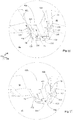
- the figures 5 and 6 make it possible to visualize the extrusion head 2 seen from the side of the lower wall 20, according to a first embodiment of the invention.
- the upstream extruder (not shown), in which the first mixture M1 is worked, opens into the lower wall 20 via an upstream extrusion channel 31, upstream (in the direction of the longitudinal direction DL) of a first blade profiling 32, called “upstream profiling blade 32”.
- This upstream profiling blade 32 defines an air gap, called an “upstream air gap”, with the radially outer wall 11 of the roller 10.
- the profile P1 is preferably of the type of that shown in figure 3 , and preferably extends continuously in the transverse direction DT.
- the downstream extruder 40 (not shown), in which the mixture M2 is worked, opens through a downstream extrusion channel 41 into the inner wall 20, downstream of the upstream profiling blade 32 and upstream of a second blade profiling 42, called “downstream profiling blade 42”.
- the flow of mixture M2 coming from the downstream extrusion channel 41 therefore comes into contact with the radially outer part of the first section P1 forming the sub-layer P14, here more particularly with the radially outer surface of said sub-layer P14, as soon as it is outlet of the downstream extrusion channel 41 directly downstream of the upstream profiling blade 32 and well upstream of the downstream profiling blade 42.
- the connection of these two flows can be a source of turbulence capable of modifying the profile of the first section P1, and in particular of the sub-layer P14, which requires an adaptation as a consequence of the transverse profile of the upstream profiling blade 32.
- the air gap between the downstream profiling blade 42 and the radially outer surface 11 of the roller 10 serves to determine the transverse profile of the second section P2 and to perfect the jointing of the sections P1 and P2 to obtain the complex section PC, PC1.
- the extrusion head 2 is advantageously provided with at least one channel 5, and preferably with several channels 5, preferably as many channels 5 as there are inserts P10, which, as will be detailed below, will form bypass conduits which (each) capture a part of the first mixture M1 intended in forming the insert P10 considered, and which transport this part of the first mixture M1 by separating it, at least temporarily, over a part of its longitudinal path between the upstream 32 and downstream 42 profiling blades, from the second mixture M2, to allow said part of the first mixture M1 intended to form the insert P10 to bypass the connection zone without coming into contact with the second mixture M2, but while remaining in continuity of material with the underlayer P14, and not to enter in contact with the second mixture M2 that then, in the downstream air gap located beyond said connection zone, sufficiently downstream of said connection zone.
- the extrusion head 2 preferably comprises at least one channel 5, formed by walls 53, 54, 55 which extend in the longitudinal direction DL between the upstream profiling blade 32 and the downstream profiling blade. 42, from an upstream end 51 of channel 5 which is located upstream of the connection zone of the flows of the first and second rubber mixtures M1, M2 to a downstream end 52 of said channel 5 which is located downstream of said zone connecting the flows and upstream of the downstream profiling blade 42.
- the invention therefore makes it possible to successively create a first confluence (a first flow connection) between the first mixture M1 and the second mixture M2, first confluence at which the second mixture M2 first comes into contact with the first mixture M1 , and more particularly in contact with the sublayer P14 forming a first element of the first section P1, then a second confluence (a second flow connection), distinct, which is offset downstream with respect to the first confluence, and at which this same second mixture M2 comes into (second) contact with second elements of this same first section P1, in this case with the insert (s) P10 concerned, which were, until this second confluence, still not exposed, because protected by their respective channels 5 which separated them from said second mixture M2.
- a first confluence a first flow connection
- the walls 53, 54, 55 of the channel 5 can extend from the upstream air gap to the downstream air gap, thus covering substantially the entire distance which separates the upstream profiling blade 32 longitudinally from the profiling blade. downstream profiling 42. As long as possible, and therefore as effective as possible, protection of the inserts P10 against the second mixture M2 will be obtained.
- the extrusion head 2 comprises at least one channel 5 which extends in the longitudinal direction DL and of which an upstream end 51 is disposed in the extension of an outlet 320 formed in the upstream profiling blade 32 and of which the The downstream end 52 opens just upstream of the downstream profiling blade 42 into the air gap defined by the downstream profiling blade 42 and the radially outer surface 11 of the roller 10.
- a channel 5 may be in the form of a channel, preferably of section substantially triangular or trapezoidal, comprising a first side wall 53 supported by a first partition 530, a second side wall 54 supported by a second partition 540, and a wall 55 forming the bottom of the channel.
- the walls 53, 54 and 55 together form a continuous concave surface, open radially inwards and the concavity of which faces the radially outer wall 11 of the roller 10.
- the walls 53, 54 and 55 of the channel 5 in a way define a duct, like a gutter or an inverted hull open at its two upstream 51 and downstream 52 ends.
- the partition 530 is preferably connected with the downstream side 321 of the upstream profiling blade 32, and the radially lower edge of the partition 530 is flush with the profile of the profiling blade upstream 32.
- the upstream profiling blade 32 has, at this upstream end 51 of the channel 5, a transverse profile in the form of an outlet 320, the downstream part of which is arranged in continuity with the wall 55 forming the bottom of the channel, so as to promote the flow of the mixture M1 in the channel 5.
- the channel 5 opens directly into the air gap formed by the downstream profiling blade 42 and the radially outer wall 11 of the roller 10.
- the partitions 530 and 540 supporting the side walls 53 and 54 of the channel 5 extend radially inwardly at a radial position lower than the position of the downstream profiling blade 42.
- the part of the mixture M1 which enters the channel 5 flows directly from the upstream end 51 to the downstream end 52 without be placed in contact with the mixture M2, so that the pressure adaptations observed at the connection of the mixture flow M2 with the mixture flow M1, do not cause any disturbance of the profile conferred on the mixture M1 having entered the channel 5 and intended for form the insert P10.
- the shaping of the insert P10 takes place throughout the progression of the mixture M1 in the channel 5, and the profile along a radial plane passing through the downstream end of the channel 5 corresponds to the profile of the insert P10 of the PC complex profile.
- the side walls P11 and P12 of the insert are joined together with the mixture M2 forming the tread is then done directly in the downstream air gap defined by the downstream profiling blade 42 and the radially outer wall 11 of the roller, without that the profile of the insert is not modified.
- the evolution of the pressure in the channel 5 can be controlled by adjusting the angle formed by the side walls 53 and 54 with respect to the longitudinal direction DL. These two walls converge towards one another going from upstream to downstream, for example by making an angle of the order of 5 ° with the longitudinal direction, so that the cross section of the channel by a plane radial or by a plane perpendicular to the longitudinal direction decreases continuously going from the upstream end 51 to the downstream end 52 of the channel, and that said section is minimal at the level of the downstream end 52.
- the section of the channel at the downstream end 52 has a substantially triangular shape corresponding to a preferred embodiment of the insert.
- the shape of this section is not limiting and can be adapted at will.
- the channels 5 illustrated by the figures 5 and 6 open out between two protrusions 420 of the downstream profiling blade 42.
- the protrusions 420 are intended to form the grooves P20 of the complex profile illustrated in figure 3 . It follows from this arrangement that the insert P10 is disposed substantially in the center of the longitudinal bead P21.
- FIGS 7 and 8 illustrate a second embodiment of the invention making it possible to produce a complex section of the type of that shown in figure 4 , and in which it is sought to position the inserts P10 at a border between the longitudinal bead P21 and the groove P20.
- the profiling head then comprises at least one separator element 6, between the upstream profiling blade and the downstream profiling blade 42, disposed in the longitudinal extension of a projection 420 of the downstream profiling blade 42 and extending from the upstream profiling blade 32 to the downstream profiling blade 42.
- This separator element 6 divides said second extrusion channel 41 into subchannels 410.
- the side wall of one or more channels 5 is then merged with the side wall 63, 64 of a separator element 6, and the respective arrangements of the walls forming the channel 5 relative to the first 32 and to the second 42 profiling blade, and described above for the first embodiment of the invention, apply mutatis mutandis.
- the radially internal wall 421 of the projection is placed at the same radial position as the radially internal wall 65 of the separator element 6.
- This wall 65 extends downstream of said projection 420 and, at its connection with the upstream profiling blade 32, occupies the same radial position as the wall of the upstream profiling blade 32.
- the second mixture M2 is joined with each of the side walls, P11 and P12, of at least one insert P10.
- the second mixture M2 is joined with a single side wall, P11 or P12, of at least one insert.
- the walls are arranged so that, the section formed by said walls and the base P13 of the insert by a radial plane passing through the axis 12, decreases between the exit of the first air gap and the entrance to the second air gap.
- the walls 53, 54, 55 are arranged so that, at the entrance to the downstream air gap, the section formed by said walls and the base P13 of the insert by a perpendicular plane in the longitudinal direction, either triangular in shape
- the walls 53, 54, 55 of the channel 5 are arranged so that the section formed by said walls and the base P13 of the insert P10 by a plane perpendicular to the longitudinal direction decreases between the outlet of the upstream air gap and the entrance to the downstream air gap.
- the profiling wall can be fixed.
- the lower wall of the extrusion head may have a concave shape of cylindrical profile with a given axis extending transversely, and a circumferential direction of which merges with the longitudinal direction DL defining the direction of progression of the profile in the machine.
- the profiling wall can then be formed by a cylindrical roller 10, movable in rotation about an axis 12 coincident with the axis of the lower wall 20, a radially outer wall 11 of which forms said wall profiling.
- the first section P1 does not present any discontinuity in the transverse direction DT.
- the overall width of the first section P1, and more particularly the overall width of its sublayer P14 formed in one piece, said overall width being considered along said transverse direction DT represents more than half, and more preferably at least 70%, of the overall width of the complex section PC, PC1, PC2 which is obtained at the outlet of the downstream air gap.
- the sub-layer P14 which is formed of a material, here the first mixture M1, more rigid than the material constituting the second profile P2 and therefore constituting the tread, namely the second mixture M2, must in fact be preferably occupy a width sufficient to effectively contribute to the good mechanical strength of the tire, in combination with an underlying reinforcing ply with which said P14 sublayer in a way forms a composite beam in the radial thickness of the tire ,.
- the inserts P10 are formed using the first material M1 and are in continuity of material with the rest of the profile P1, and more particularly with the sublayer formed in one piece on the aforementioned width.
- the complex profile PC, PC1, PC2 according to the invention can usefully be used to cap the crown of a tire blank in order to form, after molding and vulcanization, the strip of bearing of the latter.
- the figure 10 represents, according to a third variant embodiment, a third complex profile PC3 comprising a first profile P1 consisting of a first mixture M1 intended to form the underlayer and a second profile P2 consisting of a second mixture M2 intended to form the tread.
- the profile of the tread comprises longitudinal grooves P20 interposed between longitudinal cords P21.
- This third complex profile PC3 also comprises at least one edge rubber P3 comprising an edge rubber P31 placed at the bottom of the groove associated with at least one side border rubber P30 covering a side wall of a groove.
- the border gum P3 is formed from a third mixture M3.
- Said third mixture M3 may be of the same nature as the mixture M1 or, preferably, of a different nature.
- the third mixture M3 can be of the same nature as the second mixture M2.
- a fourth complex profile PC4 shown in figure 11 comprises longitudinal inserts P10 made of the mixture M1, of generally triangular shape, and which rise in the radial direction DR from a fictitious base P13 located on the radially outer face of the sublayer P1, to the radially outer surface of the second profile P2.
- These longitudinal inserts P10 are arranged at the edge of a longitudinal bead P21 at the border between the longitudinal bead P21 and the longitudinal groove P20 so that a side wall P11 or P12 of the insert forms the edge of the groove.
- the triangular shape of the insert P10 is not limiting and it is quite possible, as will be seen below, to produce inserts of different shapes as long as the base of the insert is in continuity of material. with the radially outer surface of the second profile forming the underlayer.
- the purpose of the edging rubber P3 is to cover the side walls of the insert P10 and the bottom of the groove with a third mixture M3.
- This third mixture M3 may be formed from a composition of a different nature from the compositions forming the mixtures M1 or M2, or, preferably here, of the same nature as the mixture M2, but which may also be.
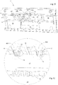
- the extrusion head 2 comprises an upstream extruder 30 (visible on the figure 9 ), in which the first mixture M1 is worked, and which opens into the lower wall 20 via an upstream extrusion channel 31 arranged upstream (in the direction of the longitudinal direction DL) of the upstream profiling blade 32.
- This upstream profiling blade 32 the transverse profile of which is adapted to shape the first section P1 intended to form the sub-layer P14, forms an air gap with the radially outer wall 11 of the roller 10.
- the first section P1 may be of type of that shown in figure 3 , and extend continuously in the transverse direction DT.
- a downstream extruder 40 (visible on the figure 9 ) in which the mixture M2 is worked, opens via a downstream extrusion channel 41 into the lower wall 20, downstream of the upstream profiling blade 32 and upstream of a downstream profiling blade 42.
- the flow of mixture M2 coming from the downstream extrusion channel 41 therefore comes into contact with the radially outer part of the first section P1 forming the sublayer as soon as it leaves the downstream extrusion channel 41 and directly downstream of the upstream profiling blade. 32, well upstream of the downstream profiling blade 42.
- the connection of these two flows can be a source of turbulence liable to modify the profile of the underlayer, which requires an adaptation as a consequence of the transverse profile of the profiling blade. upstream 32.
- downstream air gap defined between the downstream profiling blade 42 and the radially outer surface 11 of the roller 10 is used to determine the transverse profile of the complex profile PC formed by the assembly of the gums M1 and M2, and to perfect the setting. in joint of profiles P1 and P2.
- the downstream profiling blade 42 preferably comprises at least one projection 420 intended to form a longitudinal groove P20.
- downstream extrusion unit 4 is associated, in addition to the downstream extruder 40, with an annex extruder 70, visible on the figure. figure 9 , which provides the third mixture M3.
- the annex extruder 70 is connected by an internal channel running through the extrusion head 2 to the extrusion channel 71 opening into the upstream part of the projection 420 of the downstream profiling blade 42.
- This annex extrusion channel 71 is formed by two side walls 720 substantially parallel to the side walls 422 of the downstream part of the projection, and by an upstream wall 73 perpendicular to the longitudinal direction. These walls are carried by side partitions 721 and an upstream partition 731.
- the section of the annex extrusion channel 71 by a radial section plane, perpendicular to the longitudinal direction DL, defines a fictitious surface in which the entire section of the downstream part of the projection 420 is inscribed by this same plane. It will be observed that the downstream edge 723 of the side walls 721 as well as the upstream face (not visible) of the projection 420 proper coincide with this section plane.
- At least one of the side walls 720 is distant by a value d from the side wall 422 of the downstream part of the projection 420 so as to define between these two walls a lateral outlet opening 72 of width d through which the mixture M3 coming from of the annex extruder 70 is extruded to form a side border eraser P30.
- the radially lower edge 722 of the side walls 720 and the radially lower edge 732 of the upstream wall 730 are inscribed in a plane substantially perpendicular to the radial direction DR. This plane is distant from the radially internal wall 421 of the projection 420 by a value zero. And the opening in said plane of radial section between the radially lower wall 421 and the radially lower edge of the walls 720 and 730 defines a lower outlet opening 73 of height e, through which the mixture coming from the annex extruder 70 is extruded. to form the furrow bottom edge eraser P31.
- the side outlet vents 72 and the bottom outlet outlet 73 are open into one another to ensure continuity of material between the side edge gums P30 and the bottom edge gum P31.
- the radially lower space of the outlet or holes 72, 73 preferably remains open and faces the flow of material coming from upstream and entering the air gap defined by the downstream profiling blade 42 and the radially outer surface 11 of roller 10.
- the values of the distances d and e define the thicknesses of the respectively lateral P30 and lower P31 edge rubbers. These values are generally of the order of a millimeter and preferably less than this value.
- the choice between one or two side vents depends on the configuration of the complex PC, PC3, PC4 profile that you want to make, in particular if you want to cover with a edge rubber P3 one or both side faces of the groove (see figures 10 or 11 ). So the figure 14 shows an additional extrusion channel 71 comprising two side openings 72; and the figure 15 shows an additional extrusion channel 71 having only one side opening 72.
- a fourth embodiment of the invention is particularly suitable for producing complex PC4 profiles of a fourth type corresponding to that shown in figure 11 , which comprises inserts P10 arranged at the border of an edge or both side edges of a groove P20.
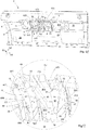
- An extrusion head 2 according to this embodiment of the invention is illustrated by the figures 16 and 17 . It differs from the extrusion head making it possible to produce the third complex profile PC3 described above in that it comprises at least one separator element 6, arranged in the longitudinal extension of the projections 420 of the downstream profiling blade 42. This separator element 6 extends from the upstream profiling blade 32 to the downstream profiling blade 42, and divides said downstream extrusion channel 41 into subchannels 410.
- the side walls 63 of the separator element 6 are arranged in continuity with the side walls 721 of the annex extrusion channel 71, and the radially internal wall 64 of the separator element 6 is arranged radially substantially at the same level as the radially lower edge 732 of the partition 731 supporting the upstream wall 730 of the outlet of the annex extrusion channel 71. Also, the upstream partition 731 supporting said upstream wall 730 can usefully be merged with the end downstream of the separator element 6.
- the radially internal wall 64 of the separator element is disposed radially at the same level as the wall of the upstream profiling blade 32.
- the extrusion head 2 also comprises at least one channel 5 extending in the longitudinal direction, from the upstream profiling blade 32 to the blade. downstream profiling 42.
- Such a channel 5 preferably has the characteristic (s) already described with reference to figures 1 to 8 , for the same purposes of protecting the insert P10 vis-à-vis the second mixture M2.
- Such a channel 5 is preferably presented here in the form of a channel of substantially triangular or trapezoidal section comprising a side wall 53 supported by a partition 530, another side wall, placed opposite the previous one, and formed by a side wall 63 of a separator element 6, and a wall 54 forming the bottom of the channel.
- the walls 53, 63 and 54 together form a continuous concave surface, open radially inwards, and the concavity of which faces the radially outer wall 11 of the roller 10.
- These walls define a duct, like a duct. gutter or an inverted shell open at both its upstream 51 and downstream 52 ends.
- the partition 530 is connected with the downstream side 321 of the downstream profiling blade 32, and the radially lower edge of the partition 530 is flush with the profile of the upstream extrusion blade 32.
- the upstream profiling blade 32 has, at this upstream end 51 of the channel 5, a transverse profile in the form of an outlet 320, the downstream part of which is arranged in continuity with the wall 55 forming the bottom of the channel, of so as to promote the flow of the mixture M1 in the channel 5.
- the channel 5 opens directly into the air gap formed by the downstream profiling blade 42 and the radially outer wall 11 of the roller 10.
- the channel 5, illustrated in figures 16 and 17 is configured so that the wall 55 forming the bottom of the channel 5 is disposed radially at the same level as the radial position at this level of the downstream profiling blade 42.
- the partition 530 supporting the side wall 53 of the channel extends radially inward at a radial position lower than the position of the downstream profiling blade 42.
- the part of the mixture M1 entering the channel 5 flows directly from the upstream end 51 to the downstream end 52 without being put into use. contact with the mixture M2, so that the pressure adaptations observed at the connection of the mixture flow M2 with the mixture flow M1, do not cause any disturbance of the profile conferred on the mixture M1 which has entered the channel 5 and intended to form the insert P10.
- the shaping of the insert P10 is done throughout the progression of the first mixture M1 in the channel 5, and the profile along a radial plane passing through the downstream end of the channel 5 corresponds to the profile of the insert P10 of the PC complex profile.
- the joining of the wall of the insert (P11 or P12) opposite the wall of the insert forming the wall of the groove with the M2 mixture forming the tread is then done directly in the air gap formed by the blade downstream profiling 42 and the radially outer wall 11 of the roller, without the profile of the insert being changed.
- the evolution of the pressure in the channel 5 can be controlled by adjusting the angle formed by the side walls 53 and 63 with respect to the longitudinal direction DL. These two walls converge towards one another going from upstream to downstream, for example making an angle of the order of 5 ° with the longitudinal direction, so that the cross section of the channel by a radial plane or by a plane perpendicular to the longitudinal direction decreases continuously going from the upstream end 51 to the downstream end 52 of the channel, and that said section is minimal at the level of the downstream end 52.
- the partition 530 of the channel supporting the side wall 53 is thin so as not to disturb the flow of material circulating on its two faces. A thickness less than 2mm and preferably less than 1mm seems to be suitable.
- the section of the channel at the downstream end 52 has a substantially triangular shape corresponding to a preferred embodiment of the insert.
- the shape of this section is not limiting and can be adapted at will.
- downstream end 52 of the channel 5 is disposed slightly upstream of the lateral openings 72 so that the lateral edge P11 of the insert P10 is formed before receiving the edge rubber P3.
- an extrusion head 2 which comprises one or more channels 5 as described above, can preferably be characterized in that the downstream profiling blade 42 comprises at least one projection 420 for form a longitudinal groove P20 in the complex profile PC, in that the channel 5 is arranged so as to dispose the insert P10 at the border of a lateral edge of said groove P20 so that a side wall P11, P12 of said insert P10 forms the edge of said groove, and in that the annex extrusion channel 71 comprises outlet openings 72, 73 arranged at the edge of said projection 420, upstream of said projection 420, and forming one or more lateral outlet openings 72 and a lower outlet opening 73, so as to be able to deposit in the groove P20 of the complex profile PC1, PC2 an edging rubber P3 which comprises a rubber of bottom edge of the groove P31 deposited on the bottom of the groove by the lower outlet opening 73 and at least one lateral border gum P30 deposited on the side wall P11, P12 of the
- the use of the outlet openings 72, 73, in combination with the channel or channels 5, makes it possible to precisely cover the side wall of the insert P10, and more generally the walls of the groove P20, with a layer of regular and fine border, in well controlled excess thickness, which can preferably be of the same composition as the second mixture M2.
- the invention relates to a corresponding method, and to variants thereof.
- a portion of the first rubber mixture M1, intended to form the insert P10 is circulated between the walls 53, 54, 55 of a channel 5 which extend in a direction longitudinal DL between the upstream profiling blade 32 and the downstream profiling blade 42, from an upstream end 51 of the channel 5 which is located upstream of the connection of the flows of the first and second rubber mixtures M1, M2 to a downstream end 52 of said channel 5 which is located downstream of said connection of the flows and upstream of the downstream profiling blade 42, said walls 53, 54, 55 of the channel together forming a concave surface open towards the interior of the extrusion cavity, and being arranged so that the portion of the first rubber mixture M1 which penetrates into the channel 5 and which is intended to form the insert P10, when it progresses longitudinally in the channel 5, remains in continuity of material with the sub- P14 layer without being put in co ntact with the second rubber mixture M2, and that the sealing of one or more side walls P11, P12 of said insert
- the downstream profiling blade 42 comprises at least one protrusion 420 to form a longitudinal groove P20 in the complex profile PC
- the insert P10 is disposed at the border of a lateral edge of said groove P20 so that a side wall P11, P12 of said insert P10 forms the edge of said groove
- a third rubber mixture M3 is delivered via an additional extrusion channel 71 which opens into an upstream part of the projection 420, said annex extrusion channel 71 comprising outlet openings 72, 73 arranged at the edge of said projection 420 and forming one or more lateral outlet openings 72 and a lower outlet opening 73 , so as to deposit in the groove P20 of the complex profile PC, PC1, PC2, PC4 an edge eraser P3 which comprises a bottom edge eraser P31 deposited on the bottom of the groove by the lower outlet opening 73 and at least one side border eraser P30 deposited on the side wall P11, P12 of the insert P10 by a side
- downstream end 52 of the channel 5 is disposed upstream of the side outlet openings 73 so that the side wall P11, P12 of the insert P10 is formed before receiving the edge rubber P3.
- a third mixture of rubber M3 which is of the same composition as the second mixture of rubber M2 is used.
- the thickness of the side border rubber P30 which covers the side wall P11, P12 of the insert P10 may be of the order of 2 mm.
- the insert P10 can be positioned laterally as desired in a block of the tread, in that the depth of depression (considered in the transverse direction DT) of said insert P10 in said block will be freely defined by the dimensioning of the openings 72 and of the downstream profiling blade 42.
- the lateral insertion depth of the insert P10 in the block of second mixture M2 may be between a minimum depth of 2 mm (thin thickness achievable by the openings 72) and a maximum depth of 12 mm, typically equivalent to half of the overall lateral dimension (generally of the order of 25 mm) of a block of the tread.
Landscapes
- Engineering & Computer Science (AREA)
- Mechanical Engineering (AREA)
- Manufacturing & Machinery (AREA)
- Extrusion Moulding Of Plastics Or The Like (AREA)
Claims (15)
- Verfahren zur Coextrusion eines komplexen Profils (PC), das von der Anordnung von Profilen (P1, P2) gebildet ist, die aus gesonderten Kautschukmischungen (M1, M2) gebildet sind, wobei mithilfe einer Coextrusionsmaschine (1), die einen stromaufwärtigen Extruder (30) und einen stromabwärtigen Extruder (40) umfasst, die in einen Extrusionshohlraum münden, der von dem Raum zwischen einer unteren Wand (20) eines Extrusionskopfs (2) und einer Profilierungswand (11), die gegenüber der unteren Wand (20) angeordnet ist, gebildet ist, die Schritte durchgeführt werden, bei denen:- mithilfe des stromaufwärtigen Extruders (30) stromauf eines ersten Profilierungsblatts (32), des "stromaufwärtigen Profilierungsblatts" (32), eine erste Kautschukmischung (M1) zugeführt wird, die durch einen stromaufwärtigen Extrusionskanal (31) in der unteren Wand (20) des Extrusionskopfs (2) mündet,- ein erstes Profil (P1), das von der ersten Kautschukmischung (M1) gebildet wird, in einem stromaufwärtigen Luftspalt hergestellt wird, der vom stromaufwärtigen Profilierungsblatt (32) und der Profilierungswand (11) gebildet ist, wobei das erste Profil (P1) mindestens ein erstes Profilelement zur Bildung einer Unterschicht (P14) und mindestens ein zweites Profilelement zur Bildung eines Längseinsatzes (P10), dessen eine Basis (P13) stoffschlüssig mit der Unterschicht (P14) ausgebildet ist und der auf der Unterschicht (P14) eine Erhöhung bildet, deren Seitenwände (P11, P12) sich bezogen auf eine Außenfläche des ersten Profils nach außen erstrecken, umfasst,- mithilfe des stromabwärtigen Extruders (40) eine zweite Kautschukmischung (M2) durch einen stromabwärtigen Extrusionskanal (41) zugeführt wird, der in der unteren Wand (20) des Extrusionskopfs (2) stromab des stromaufwärtigen Profilierungsblatts (32) mündet, und an einer Verbindungsstelle des Stroms der zweiten Kautschukmischung (M2) mit dem Strom der ersten Kautschukmischung (M1) die zweite Kautschukmischung (M2) mit der radial äußeren Fläche des ersten Profils (P1) in Verbindung gebracht wird,- das erste Profil (P1) und die zweite Kautschukmischung (M2) in einen stromabwärtigen Luftspalt geleitet werden, der stromab des stromabwärtigen Extrusionskanals (40) angeordnet ist und der von einem zweiten Profilierungsblatt (42), dem "stromabwärtigen Profilierungsblatt" (42), und der Profilierungswand (11) definiert ist, um ein komplexes Profil (PC) herzustellen, das von der ersten und zweiten Kautschukmischung (M1, M2) gebildet ist,
wobei das Verfahren dadurch gekennzeichnet ist, dass ein Anteil der ersten Kautschukmischung (M1), der dazu bestimmt ist, den Einsatz (P10) zu bilden, zwischen Wänden (53, 54, 55) einer Rinne (5) strömen gelassen wird, die sich in einer Längsrichtung (DL) zwischen dem stromaufwärtigen Profilierungsblatt (32) und dem stromabwärtigen Profilierungsblatt (42) von einem stromaufwärtigen Ende (51) der Rinne (5), das sich stromauf der Verbindungsstelle der Ströme der ersten und zweiten Kautschukmischung (M1, M2) befindet, bis zu einem stromabwärtigen Ende (52) der Rinne (5), das sich stromab der Verbindungsstelle der Ströme und stromauf des stromabwärtigen Profilierungsblatts (42) befindet, erstrecken, wobei die Wände (53, 54, 55) der Rinne zusammen eine konkave Fläche bilden, die zum Inneren des Extrusionshohlraums offen ist, und so angeordnet sind, dass der Anteil der ersten Kautschukmischung (M1), der in die Rinne (5) eindringt und dazu bestimmt ist, den Einsatz (P10) zu bilden, wenn er sich in der Rinne (5) in Längsrichtung voran bewegt, mit der Unterschicht (P14) stoffschlüssig bleibt, ohne mit der zweiten Kautschukmischung (M2) in Kontakt gebracht zu werden, und dass das Inverbindungbringen einer oder der Seitenwände (P11, P12) des Einsatzes (P10) mit der zweiten Kautschukmischung (M2) anschließend im stromabwärtigen Luftspalt erfolgt, der vom stromabwärtigen Profilierungsblatt (42) und der Profilierungswand (11) definiert ist. - Coextrusionsverfahren nach Anspruch 1, wobei sich die Wände (53, 54, 55) der Rinne (5) vom stromaufwärtigen Luftspalt bis zum stromabwärtigen Luftspalt erstrecken.
- Coextrusionsverfahren nach Anspruch 1 oder 2, wobei das stromabwärtige Profilierungsblatt (42) mindestens einen Vorsprung (420) zur Bildung einer Längsnut (P20) im komplexen Profil (PC) umfasst, wobei in dem Verfahren der Einsatz (P10) an der Grenze eines Seitenrands der Nut (P20) angeordnet ist, so dass eine Seitenwand (P11, P12) des Einsatzes (P10) den Rand der Nut bildet, und wobei mithilfe eines Nebenextruders (70) eine dritte Kautschukmischung (M3) durch einen Nebenextrusionskanal (71) zugeführt wird, der in einem stromaufwärtigen Abschnitt des Vorsprungs (420) mündet, wobei der Nebenextrusionskanal (71) Auslasskiemen (72, 73) aufweist, die am Rand des Vorsprungs (420) angeordnet sind und eine oder mehrere Seitenauslasskiemen (72) und eine untere Auslasskieme (73) bilden, um in der Nut (P20) des komplexen Profils (PC, PC1, PC2, PC4) ein Randgummi (P3) anzuordnen, das ein Nutboden-Randgummi (P31), das über die untere Auslasskieme (73) auf den Boden der Nut aufgebracht wird, und mindestens ein Seitenrand-Gummi (P30), das über eine Seitenauslasskieme (72) auf die Seitenwand (P11, P12) des Einsatzes (P10) aufgebracht wird, umfasst.
- Verfahren nach Anspruch 3, wobei das stromabwärtige Ende (52) der Rinne (5) stromauf der Seitenauslasskiemen (73) so angeordnet ist, dass die Seitenwand (P11, P12) des Einsatzes (P10) vor der Aufnahme des Randgummis (P3) gebildet ist.
- Verfahren nach Anspruch 3 oder 4, wobei zur Bildung des Randgummis (P3) eine dritte Kautschukmischung (M3) genutzt wird, die dieselbe Zusammensetzung wie die zweite Kautschukmischung (M2) aufweist.
- Coextrusionsverfahren nach einem der vorhergehenden Ansprüche, wobei während seiner Voranbewegung in der Rinne der Querschnitt des Einsatzes (P10) in einer Ebene senkrecht zur Längsrichtung zwischen dem Ausgang des stromaufwärtigen Luftspalts und dem Eingang des stromabwärtigen Luftspalts abnimmt.
- Coextrusionsverfahren nach einem der vorhergehenden Ansprüche, wobei am Eingang des stromaufwärtigen Luftspalts der Querschnitt des Einsatzes (P10) in einer Ebene senkrecht zur Längsrichtung eine dreieckige Form aufweist.
- Coextrusionsverfahren nach einem der vorhergehenden Ansprüche, wobei am Ausgang des stromabwärtigen Luftspalts ein äußerer Scheitelpunkt des Einsatzes (P10) bündig mit der Außenfläche des komplexen Profils (PC) ist.
- Coextrusionsverfahren nach einem der vorhergehenden Ansprüche, wobei die zweite Mischung (M2) mit jeder der Seitenwände (P11, P12) mindestens eines Einsatzes (P10) in Verbindung gebracht wird.
- Coextrusionsverfahren nach einem der vorhergehenden Ansprüche, wobei die zweite Mischung (M2) mit einer einzelnen der Seitenwände (P11, P12) mindestens eines Einsatzes (P10) in Verbindung gebracht wird.
- Coextrusionsverfahren nach einem der vorhergehenden Ansprüche, wobei ein erstes Profil (P1) extrudiert wird, das keine Unterbrechung in einer Querrichtung (DT) senkrecht zur Längsrichtung aufweist, und dessen Breite über alles in der Querrichtung (DT) betrachtet vorzugsweise mehr als die Hälfte, und besser noch mindestens 70% der Breite über alles des erhaltenen komplexen Profils (PC) darstellt.
- Coextrusionsverfahren nach einem der vorhergehenden Ansprüche, wobei- die untere Wand des Extrusionskopfs eine konkave Form eines bestimmten zylindrischen Achsenprofils aufweist, das sich in Querrichtung erstreckt, und dessen eine Umfangsrichtung mit der Längsrichtung zusammenfällt, die die Voranbewegungsrichtung des Profils in der Maschine definiert, und- die Profilierungswand von einer zylindrischen Rolle (10) gebildet ist, die um eine Achse (12) drehbeweglich ist, die mit der Achse der unteren Wand (20) zusammenfällt, deren eine radial äußere Wand (11) die Profilierungswand bildet.
- Reifen, der von einem komplexen Profil gebildet ist, der mithilfe eines Coextrusionsverfahrens nach einem der Ansprüche 1 bis 12 hergestellt ist.
- Extrusionskopf (2) für ein komplexes Profil, das aus der Anordnung von Profilen (P1, P2) gebildet ist, die aus gesonderten Kautschukmischungen (M1, M2) gebildet sind, der dazu bestimmt ist, an einer Coextrusionsmaschine (1) angebracht zu sein, und wobei sich die Profile in einem Extrusionshohlraum in einer Extrusionsrichtung von stromauf nach stromab unter Definition einer Längsrichtung (DL) voran bewegen, wobei der Extrusionskopf (2) eine untere Wand (20) umfasst, die den Extrusionshohlraum teilweise begrenzt, und unter Voranbewegung von stromauf nach stromab der unteren Wand (20) in der Längsrichtung (DL):- einen stromaufwärtigen Extrusionsblock (3), der einen stromaufwärtigen Extrusionskanal (31) aufweist, der am Ausgang eines stromaufwärtigen Extruders (30) platziert ist und der in der unteren Wand (20) mündet, um einen Strom einer ersten Kautschukmischung (M1) zuführen zu können,- ein stromaufwärtiges Profilierungsblatt (32), das in Querrichtung stromab des stromaufwärtigen Extrusionskanals (31) angeordnet ist, um ein erstes Querprofil eines ersten Profils (P1) zu bestimmen, das aus dem Strom der ersten Kautschukmischung (M1) gebildet ist,- einen stromabwärtigen Extrusionsblock (4), der einen stromabwärtigen Extrusionskanal (41) aufweist, der am Ausgang eines stromabwärtigen Extruders (40) platziert ist und der in der unteren Wand (20) stromab des stromaufwärtigen Profilierungsblatts (32) mündet, um einen Strom einer zweiten Kautschukmischung (M2) zuführen zu können und den Strom der zweiten Mischung an einem Stromverbindungsbereich mit dem Strom der ersten Kautschukmischung (M1) in Verbindung zu bringen,- ein stromabwärtiges Profilierungsblatt (42), das in Querrichtung stromab des stromabwärtigen Extrusionskanals (41) und des Stromverbindungsbereichs angeordnet ist, um ein Querprofil des komplexen Profils (PC) zu bestimmen, das aus der ersten und zweiten Kautschukmischung (M1, M2) gebildet ist,
dadurch gekennzeichnet, dass der Extrusionskopf mindestens eine Rinne (5) aufweist, die von Wänden (53, 54, 55) gebildet ist, die sich in der Längsrichtung (DL) zwischen dem stromaufwärtigen Profilierungsblatt (32) und dem stromabwärtigen Profilierungsblatt (42) von einem stromaufwärtigen Ende (51) der Rinne (5), das sich stromauf der Verbindungsstelle der Ströme der ersten und zweiten Kautschukmischung (M1, M2) befindet, bis zu einem stromabwärtigen Ende (52) der Rinne (5), das sich stromab der Verbindungsstelle der Ströme und stromauf des stromabwärtigen Profilierungsblatts (42) befindet, erstrecken, wobei die Wände (53, 54, 55) der Rinne zusammen eine konkave Fläche bilden, die zum Inneren des Extrusionshohlraums offen ist, und so angeordnet sind, dass einerseits ein Anteil des Stroms der ersten Kautschukmischung (M1), der dazu bestimmt ist, einen Einsatz (P10) im komplexen Profil (PC) zu bilden, in die Rinne (5) eindringen und sich in Längsrichtung in der Rinne (5) voran bewegen kann, ohne mit der zweiten Kautschukmischung (M2) in Kontakt gebracht zu werden, dabei jedoch mit einer Unterschicht (P14) des ersten Profils (P1) aus der ersten Kautschukmischung (M1) stoffschlüssig bleibt, die in einem stromaufwärtigen Luftspalt in Form gebracht worden sein wird, der vom stromaufwärtigen Profilierungsblatt (32) definiert ist, und dass andererseits ein Inverbindungbringen einer oder mehrerer Seitenwände (P11, P12) des Einsatzes (P10) mit der zweiten Kautschukmischung (M2) anschließend in einem stromabwärtigen Luftspalt erfolgt, der vom stromabwärtigen Profilierungsblatt (42) definiert ist. - Extrusionskopf nach Anspruch 14, dadurch gekennzeichnet, dass das stromabwärtige Profilierungsblatt (42) mindestens einen Vorsprung (420) zur Bildung einer Längsnut (P20) im komplexen Profil (PC) umfasst, dadurch, dass die Rinne (5) so angeordnet ist, dass sie den Einsatz (P10) an der Grenze eines Seitenrands der Nut (P20) so anordnet, dass eine Seitenwand (P11, P12) des Einsatzes (P10) den Rand der Nut bildet, und dadurch, dass der Nebenextrusionskanal (71) Auslasskiemen (72, 73) aufweist, die am Rand des Vorsprungs (420) stromauf des Vorsprungs (420) angeordnet sind und eine oder mehrere Seitenauslasskiemen (72) und eine untere Auslasskieme (73) bilden, damit in der Nut (P20) des komplexen Profils (PC1, PC2) ein Randgummi (P3) angeordnet werden kann, das ein Nutboden-Randgummi (P31), das über die untere Auslasskieme (73) auf den Boden der Nut aufgebracht ist, und mindestens ein Seitenrand-Gummi (P30), das über eine Seitenauslasskieme (72) auf die Seitenwand (P11, P12) des Einsatzes (P10) aufgebracht ist, umfasst.
Applications Claiming Priority (3)
| Application Number | Priority Date | Filing Date | Title |
|---|---|---|---|
| FR1756132A FR3068279B1 (fr) | 2017-06-30 | 2017-06-30 | Tete d'extrusion d'un profile complexe comprenant une gomme de bordure en fond de sillon |
| FR1756133A FR3068278A1 (fr) | 2017-06-30 | 2017-06-30 | Procede d'extrusion d'un profile complexe comprenant un insert |
| PCT/FR2018/051599 WO2019002782A1 (fr) | 2017-06-30 | 2018-06-28 | Tete d'extrusion avec chenaux pour la réalisation d'inserts dans une bande profilée destinée à la fabrication d'un pneumatique et procédé d'extrusion correspondant |
Publications (2)
| Publication Number | Publication Date |
|---|---|
| EP3645236A1 EP3645236A1 (de) | 2020-05-06 |
| EP3645236B1 true EP3645236B1 (de) | 2021-04-07 |
Family
ID=63442718
Family Applications (1)
| Application Number | Title | Priority Date | Filing Date |
|---|---|---|---|
| EP18762351.7A Active EP3645236B1 (de) | 2017-06-30 | 2018-06-28 | Extrusionskopf mit kanälen zur herstellung von einsätzen in einem profilband zur herstellung eines luftreifens und entsprechendes extrusionsverfahren |
Country Status (4)
| Country | Link |
|---|---|
| US (1) | US11440235B2 (de) |
| EP (1) | EP3645236B1 (de) |
| CN (1) | CN110831739B (de) |
| WO (1) | WO2019002782A1 (de) |
Families Citing this family (4)
| Publication number | Priority date | Publication date | Assignee | Title |
|---|---|---|---|---|
| FR3116016B1 (fr) * | 2020-11-06 | 2022-12-16 | Michelin & Cie | Dispositif de Mise en Forme Complexe Pour Fabriquer un Produit Complexe à Partir de Couches Caoutchouteuses Non-Débordantes |
| FR3116751B1 (fr) | 2020-11-27 | 2022-11-04 | Michelin & Cie | Installation de coextrusion permettant de realiser une bande de roulement presentant des inserts de renfort enfouis en profondeur dans les blocs de sculpture |
| FR3116750B1 (fr) | 2020-11-27 | 2022-11-04 | Michelin & Cie | Procédé de fabrication d’une bande de roulement par coextrusion avec intégration d’une interface de découplage entre blocs de sculpture et coins de renfort |
| CN113306116A (zh) * | 2021-06-11 | 2021-08-27 | 常州富烯科技股份有限公司 | 取向控制元件及成型装置 |
Family Cites Families (34)
| Publication number | Priority date | Publication date | Assignee | Title |
|---|---|---|---|---|
| US3814160A (en) * | 1972-09-18 | 1974-06-04 | Ppg Industries Inc | Tread wear indicator |
| US4478266A (en) * | 1982-09-17 | 1984-10-23 | The Goodyear Tire & Rubber Company | Composite tread having good traction and reduced rolling resistance upon wear |
| US4526528A (en) * | 1984-06-28 | 1985-07-02 | The Goodyear Tire & Rubber Company | Apparatus for forming a co-extrusion from extruded strips |
| US4683095A (en) | 1985-05-08 | 1987-07-28 | The Uniroyal Goodrich Tire Company | Early progressive junction extrusion process and system |
| US5017118A (en) * | 1989-06-16 | 1991-05-21 | The Goodyear Tire & Rubber Company | Apparatus for forming a coextrusion from extruded strips |
| FR2648388B1 (fr) | 1989-06-16 | 1992-09-04 | Goodyear Tire & Rubber | Appareil d'extrusion a filiere a rouleau, notamment pour element coextrude pour pneumatique |
| FR2700291A1 (fr) * | 1993-01-08 | 1994-07-13 | Michelin & Cie | Appareil d'extrusion et procédé d'extrusion pour mélanges de caoutchouc cru. |
| DE69717958T2 (de) * | 1996-10-17 | 2003-04-30 | Sumitomo Rubber Industries Ltd., Kobe | Luftreifen |
| IT1290520B1 (it) * | 1997-04-03 | 1998-12-04 | Pirelli | Metodo ed apparato di estrusione per realizzare fasce battistrada per pneumatici di veicoli |
| US6294119B1 (en) | 1997-12-26 | 2001-09-25 | Bridgestone Corporation | Production of unvulcanized tread rubber for pneumatic tires |
| US6695606B1 (en) | 1998-01-29 | 2004-02-24 | The Goodyear Tire & Rubber Company | Extrudate shrinkage control and reduction |
| DE60229974D1 (de) | 2001-05-16 | 2009-01-02 | Michelin Soc Tech | Vorrichtung zum koextrudieren von kautschukmischungen |
| JP4342874B2 (ja) * | 2003-08-20 | 2009-10-14 | 住友ゴム工業株式会社 | 空気入りタイヤ |
| US7334618B2 (en) * | 2003-09-03 | 2008-02-26 | Sumitomo Rubber Industries, Ltd. | Pneumatic tire with tread having cap layer and spaced apart base layers |
| ES2304556T3 (es) * | 2003-12-30 | 2008-10-16 | Pirelli Tyre S.P.A. | Neumatico y procedimiento para su fabricacion. |
| US20080216930A1 (en) * | 2007-03-05 | 2008-09-11 | Christopher John Valentine | Tyre with rubber tread which contains internal circumferential rubber stabilizer bars |
| US9205704B2 (en) * | 2007-09-27 | 2015-12-08 | The Goodyear Tire & Rubber Company | Tire having tread with repellent groove surface |
| FR2959960B1 (fr) * | 2010-05-11 | 2014-05-16 | Michelin Soc Tech | Procede de realisation d'une bande de roulement pour un pneumatique de vehicule |
| FR2968592B1 (fr) * | 2010-12-13 | 2013-01-11 | Michelin Soc Tech | Procede de fabrication d'une ebauche de pneumatique au moyen d'une nappe comprenant deux gommes |
| US8414284B2 (en) * | 2011-01-04 | 2013-04-09 | The Goodyear Tire & Rubber Company | Extruder and roller-die combination |
| WO2013049561A1 (en) * | 2011-09-28 | 2013-04-04 | Inteva Products Llc. | Method for multi-color vehicle interior components and components formed from the method |
| WO2013181211A1 (en) * | 2012-05-30 | 2013-12-05 | Exatec, Llc | Plastic assembly, methods of making and using the same, and articles comprising the same |
| US9050859B2 (en) * | 2012-08-07 | 2015-06-09 | The Goodyear Tire & Rubber Company | Tread made from multi cap compounds |
| US9027615B2 (en) * | 2012-09-12 | 2015-05-12 | The Goodyear Tire & Rubber Company | Tire tread with groove reinforcement |
| KR101405064B1 (ko) * | 2012-12-20 | 2014-06-10 | 한국타이어 주식회사 | 멀티 트레드와 멀티 트레드를 압출하는 프리포머 다이 |
| FR3001654B1 (fr) * | 2013-02-01 | 2015-06-19 | Michelin & Cie | Appareil et procede pour extruder un melange d'elastomere |
| JP2014180785A (ja) | 2013-03-18 | 2014-09-29 | Bridgestone Corp | ゴム成形装置及びゴム成形方法 |
| DE102014117068B4 (de) * | 2014-11-21 | 2020-04-23 | KraussMaffei Extrusion GmbH | Mehrfach-Strangpresskopf sowie Laufprofil-Herstellvorrichtung zum Herstellen von Laufprofilen von Fahrzeugreifen |
| FR3037531A1 (fr) | 2015-06-19 | 2016-12-23 | Michelin & Cie | Pneumatique avec un sommet comportant un element de renforcement et une bande de roulement a forte adherence |
| US20170001399A1 (en) * | 2015-06-30 | 2017-01-05 | The Goodyear Tire & Rubber Company | Method for forming a tread |
| FR3046104B1 (fr) * | 2015-12-23 | 2017-12-22 | Michelin & Cie | Procede de coextrusion d’un profile caoutchouteux complexe destine a la fabrication d’un pneumatique |
| FR3046105B1 (fr) * | 2015-12-23 | 2017-12-22 | Michelin & Cie | Tete de coextrusion d’un profile caoutchouteux complexe destine a la fabrication d’un pneumatique |
| US10427463B2 (en) * | 2016-11-16 | 2019-10-01 | The Goodyear Tire & Rubber Company | Pneumatic tire having a dual layer tread |
| FR3060436A1 (fr) * | 2016-12-20 | 2018-06-22 | Compagnie Generale Des Etablissements Michelin | Procede de coextrusion d’un profile caoutchouteux complexe destine a la fabrication d’un pneumatique |
-
2018
- 2018-06-28 EP EP18762351.7A patent/EP3645236B1/de active Active
- 2018-06-28 CN CN201880043797.XA patent/CN110831739B/zh active Active
- 2018-06-28 WO PCT/FR2018/051599 patent/WO2019002782A1/fr not_active Ceased
- 2018-06-28 US US16/623,113 patent/US11440235B2/en active Active
Also Published As
| Publication number | Publication date |
|---|---|
| US11440235B2 (en) | 2022-09-13 |
| CN110831739A (zh) | 2020-02-21 |
| US20200114565A1 (en) | 2020-04-16 |
| WO2019002782A1 (fr) | 2019-01-03 |
| CN110831739B (zh) | 2021-07-27 |
| EP3645236A1 (de) | 2020-05-06 |
Similar Documents
| Publication | Publication Date | Title |
|---|---|---|
| EP2855135B1 (de) | Verfahren zur herstellung einer flexiblen wand in einer nut eines laufstreifens für einen reifen | |
| EP3393748B1 (de) | Verfahren zum coextrudieren eines komplexen kautschukprofils zur herstellung eines reifens | |
| WO2019002782A1 (fr) | Tete d'extrusion avec chenaux pour la réalisation d'inserts dans une bande profilée destinée à la fabrication d'un pneumatique et procédé d'extrusion correspondant | |
| EP1448355B1 (de) | Vorrichtung zum koextrudieren von kautschukmischungen | |
| CA2799745C (fr) | Armature thermoplastique pour profile d'etancheite ou d'enjoliveur de vehicule automobile, profile l'incorporant et procede de fabrication d'armatures | |
| CA2226704A1 (fr) | Procede de fabrication de moule de bande de roulement | |
| FR2775220A1 (fr) | Pneumatique conducteur d'electricite et appareillage d'extrusion d'un profile avec insert conducteur | |
| EP2379354A1 (de) | Verfahren zur herstellung eines reifenwulstes und reifenwulst | |
| CA2326656C (fr) | Moule de bande de roulement | |
| EP3393749B1 (de) | Koextrusionskopf zum koextrudieren eines komplexen gummiprofils zur herstellung eines reifens | |
| CA2321910A1 (fr) | Pneumatique electriquement conducteur et appareillages d'extrusion de profiles rendus conducteurs | |
| FR2683190A1 (fr) | Profile pour pare-brise et son procede de fabrication. | |
| EP3700731B1 (de) | Kopf zum extrudieren eines komplexen profils aus nebeneinanderliegenden profilen | |
| WO2015092156A1 (fr) | Profile moule par multi-injection formant un joint d'etancheite ou un enjoliveur pour vehicule automobile, procede et moule pour sa fabrication | |
| FR3060436A1 (fr) | Procede de coextrusion d’un profile caoutchouteux complexe destine a la fabrication d’un pneumatique | |
| FR3068281A1 (fr) | Procede d'extrusion d'un profile complexe comprenant une gomme de bordure en fond de sillon | |
| FR3068280A1 (fr) | Tete d'extrusion d'un profile complexe comprenant un insert | |
| FR3068279A1 (fr) | Tete d'extrusion d'un profile complexe comprenant une gomme de bordure en fond de sillon | |
| EP3691882B1 (de) | Kopf zum extrudieren eines komplexen profilabschnitts mit einem einsatz aus einer hochelastischen mischung | |
| CA2599845C (fr) | Procede de moulage d'un boyau profile sur un vitrage | |
| EP4251397B1 (de) | Koextrusionsanlage und verfahren zur herstellung einer lauffläche mit in der tiefe in den laufflächenprofilblöcken eingebetteten verstärkungseinlagen | |
| FR3068278A1 (fr) | Procede d'extrusion d'un profile complexe comprenant un insert | |
| EP4251398B1 (de) | Verfahren zur herstellung einer lauffläche durch koextrusion mit integration einer entkopplungsschnittstelle zwischen laufflächenprofilblöcken und verstärkungskeilen | |
| FR3060435A1 (fr) | Tete de coextrusion d'un profile caoutchouteux complexe destine a la fabrication d'un pneumatique |
Legal Events
| Date | Code | Title | Description |
|---|---|---|---|
| STAA | Information on the status of an ep patent application or granted ep patent |
Free format text: STATUS: UNKNOWN |
|
| STAA | Information on the status of an ep patent application or granted ep patent |
Free format text: STATUS: THE INTERNATIONAL PUBLICATION HAS BEEN MADE |
|
| PUAI | Public reference made under article 153(3) epc to a published international application that has entered the european phase |
Free format text: ORIGINAL CODE: 0009012 |
|
| STAA | Information on the status of an ep patent application or granted ep patent |
Free format text: STATUS: REQUEST FOR EXAMINATION WAS MADE |
|
| 17P | Request for examination filed |
Effective date: 20200130 |
|
| AK | Designated contracting states |
Kind code of ref document: A1 Designated state(s): AL AT BE BG CH CY CZ DE DK EE ES FI FR GB GR HR HU IE IS IT LI LT LU LV MC MK MT NL NO PL PT RO RS SE SI SK SM TR |
|
| AX | Request for extension of the european patent |
Extension state: BA ME |
|
| DAV | Request for validation of the european patent (deleted) | ||
| DAX | Request for extension of the european patent (deleted) | ||
| GRAP | Despatch of communication of intention to grant a patent |
Free format text: ORIGINAL CODE: EPIDOSNIGR1 |
|
| STAA | Information on the status of an ep patent application or granted ep patent |
Free format text: STATUS: GRANT OF PATENT IS INTENDED |
|
| RIC1 | Information provided on ipc code assigned before grant |
Ipc: B29D 30/06 20060101ALN20201020BHEP Ipc: B29C 48/07 20190101ALN20201020BHEP Ipc: B29C 48/21 20190101ALI20201020BHEP Ipc: B29C 48/49 20190101AFI20201020BHEP Ipc: B29L 30/00 20060101ALN20201020BHEP Ipc: B29C 48/12 20190101ALI20201020BHEP Ipc: B29C 48/35 20190101ALI20201020BHEP |
|
| INTG | Intention to grant announced |
Effective date: 20201106 |
|
| GRAS | Grant fee paid |
Free format text: ORIGINAL CODE: EPIDOSNIGR3 |
|
| GRAA | (expected) grant |
Free format text: ORIGINAL CODE: 0009210 |
|
| STAA | Information on the status of an ep patent application or granted ep patent |
Free format text: STATUS: THE PATENT HAS BEEN GRANTED |
|
| AK | Designated contracting states |
Kind code of ref document: B1 Designated state(s): AL AT BE BG CH CY CZ DE DK EE ES FI FR GB GR HR HU IE IS IT LI LT LU LV MC MK MT NL NO PL PT RO RS SE SI SK SM TR |
|
| REG | Reference to a national code |
Ref country code: GB Ref legal event code: FG4D Free format text: NOT ENGLISH |
|
| REG | Reference to a national code |
Ref country code: CH Ref legal event code: EP Ref country code: AT Ref legal event code: REF Ref document number: 1379098 Country of ref document: AT Kind code of ref document: T Effective date: 20210415 |
|
| REG | Reference to a national code |
Ref country code: DE Ref legal event code: R096 Ref document number: 602018015318 Country of ref document: DE |
|
| REG | Reference to a national code |
Ref country code: IE Ref legal event code: FG4D Free format text: LANGUAGE OF EP DOCUMENT: FRENCH |
|
| REG | Reference to a national code |
Ref country code: NL Ref legal event code: FP |
|
| REG | Reference to a national code |
Ref country code: LT Ref legal event code: MG9D |
|
| REG | Reference to a national code |
Ref country code: AT Ref legal event code: MK05 Ref document number: 1379098 Country of ref document: AT Kind code of ref document: T Effective date: 20210407 |
|
| PG25 | Lapsed in a contracting state [announced via postgrant information from national office to epo] |
Ref country code: HR Free format text: LAPSE BECAUSE OF FAILURE TO SUBMIT A TRANSLATION OF THE DESCRIPTION OR TO PAY THE FEE WITHIN THE PRESCRIBED TIME-LIMIT Effective date: 20210407 Ref country code: LT Free format text: LAPSE BECAUSE OF FAILURE TO SUBMIT A TRANSLATION OF THE DESCRIPTION OR TO PAY THE FEE WITHIN THE PRESCRIBED TIME-LIMIT Effective date: 20210407 Ref country code: FI Free format text: LAPSE BECAUSE OF FAILURE TO SUBMIT A TRANSLATION OF THE DESCRIPTION OR TO PAY THE FEE WITHIN THE PRESCRIBED TIME-LIMIT Effective date: 20210407 Ref country code: AT Free format text: LAPSE BECAUSE OF FAILURE TO SUBMIT A TRANSLATION OF THE DESCRIPTION OR TO PAY THE FEE WITHIN THE PRESCRIBED TIME-LIMIT Effective date: 20210407 Ref country code: BG Free format text: LAPSE BECAUSE OF FAILURE TO SUBMIT A TRANSLATION OF THE DESCRIPTION OR TO PAY THE FEE WITHIN THE PRESCRIBED TIME-LIMIT Effective date: 20210707 |
|
| PG25 | Lapsed in a contracting state [announced via postgrant information from national office to epo] |
Ref country code: PT Free format text: LAPSE BECAUSE OF FAILURE TO SUBMIT A TRANSLATION OF THE DESCRIPTION OR TO PAY THE FEE WITHIN THE PRESCRIBED TIME-LIMIT Effective date: 20210809 Ref country code: SE Free format text: LAPSE BECAUSE OF FAILURE TO SUBMIT A TRANSLATION OF THE DESCRIPTION OR TO PAY THE FEE WITHIN THE PRESCRIBED TIME-LIMIT Effective date: 20210407 Ref country code: RS Free format text: LAPSE BECAUSE OF FAILURE TO SUBMIT A TRANSLATION OF THE DESCRIPTION OR TO PAY THE FEE WITHIN THE PRESCRIBED TIME-LIMIT Effective date: 20210407 Ref country code: PL Free format text: LAPSE BECAUSE OF FAILURE TO SUBMIT A TRANSLATION OF THE DESCRIPTION OR TO PAY THE FEE WITHIN THE PRESCRIBED TIME-LIMIT Effective date: 20210407 Ref country code: NO Free format text: LAPSE BECAUSE OF FAILURE TO SUBMIT A TRANSLATION OF THE DESCRIPTION OR TO PAY THE FEE WITHIN THE PRESCRIBED TIME-LIMIT Effective date: 20210707 Ref country code: LV Free format text: LAPSE BECAUSE OF FAILURE TO SUBMIT A TRANSLATION OF THE DESCRIPTION OR TO PAY THE FEE WITHIN THE PRESCRIBED TIME-LIMIT Effective date: 20210407 Ref country code: IS Free format text: LAPSE BECAUSE OF FAILURE TO SUBMIT A TRANSLATION OF THE DESCRIPTION OR TO PAY THE FEE WITHIN THE PRESCRIBED TIME-LIMIT Effective date: 20210807 Ref country code: GR Free format text: LAPSE BECAUSE OF FAILURE TO SUBMIT A TRANSLATION OF THE DESCRIPTION OR TO PAY THE FEE WITHIN THE PRESCRIBED TIME-LIMIT Effective date: 20210708 |
|
| REG | Reference to a national code |
Ref country code: DE Ref legal event code: R097 Ref document number: 602018015318 Country of ref document: DE |
|
| PG25 | Lapsed in a contracting state [announced via postgrant information from national office to epo] |
Ref country code: SK Free format text: LAPSE BECAUSE OF FAILURE TO SUBMIT A TRANSLATION OF THE DESCRIPTION OR TO PAY THE FEE WITHIN THE PRESCRIBED TIME-LIMIT Effective date: 20210407 Ref country code: ES Free format text: LAPSE BECAUSE OF FAILURE TO SUBMIT A TRANSLATION OF THE DESCRIPTION OR TO PAY THE FEE WITHIN THE PRESCRIBED TIME-LIMIT Effective date: 20210407 Ref country code: EE Free format text: LAPSE BECAUSE OF FAILURE TO SUBMIT A TRANSLATION OF THE DESCRIPTION OR TO PAY THE FEE WITHIN THE PRESCRIBED TIME-LIMIT Effective date: 20210407 Ref country code: CZ Free format text: LAPSE BECAUSE OF FAILURE TO SUBMIT A TRANSLATION OF THE DESCRIPTION OR TO PAY THE FEE WITHIN THE PRESCRIBED TIME-LIMIT Effective date: 20210407 Ref country code: DK Free format text: LAPSE BECAUSE OF FAILURE TO SUBMIT A TRANSLATION OF THE DESCRIPTION OR TO PAY THE FEE WITHIN THE PRESCRIBED TIME-LIMIT Effective date: 20210407 Ref country code: MC Free format text: LAPSE BECAUSE OF FAILURE TO SUBMIT A TRANSLATION OF THE DESCRIPTION OR TO PAY THE FEE WITHIN THE PRESCRIBED TIME-LIMIT Effective date: 20210407 Ref country code: SM Free format text: LAPSE BECAUSE OF FAILURE TO SUBMIT A TRANSLATION OF THE DESCRIPTION OR TO PAY THE FEE WITHIN THE PRESCRIBED TIME-LIMIT Effective date: 20210407 Ref country code: RO Free format text: LAPSE BECAUSE OF FAILURE TO SUBMIT A TRANSLATION OF THE DESCRIPTION OR TO PAY THE FEE WITHIN THE PRESCRIBED TIME-LIMIT Effective date: 20210407 |
|
| REG | Reference to a national code |
Ref country code: CH Ref legal event code: PL |
|
| PLBE | No opposition filed within time limit |
Free format text: ORIGINAL CODE: 0009261 |
|
| STAA | Information on the status of an ep patent application or granted ep patent |
Free format text: STATUS: NO OPPOSITION FILED WITHIN TIME LIMIT |
|
| REG | Reference to a national code |
Ref country code: BE Ref legal event code: MM Effective date: 20210630 |
|
| 26N | No opposition filed |
Effective date: 20220110 |
|
| PG25 | Lapsed in a contracting state [announced via postgrant information from national office to epo] |
Ref country code: LU Free format text: LAPSE BECAUSE OF NON-PAYMENT OF DUE FEES Effective date: 20210628 |
|
| PG25 | Lapsed in a contracting state [announced via postgrant information from national office to epo] |
Ref country code: LI Free format text: LAPSE BECAUSE OF NON-PAYMENT OF DUE FEES Effective date: 20210630 Ref country code: IE Free format text: LAPSE BECAUSE OF NON-PAYMENT OF DUE FEES Effective date: 20210628 Ref country code: CH Free format text: LAPSE BECAUSE OF NON-PAYMENT OF DUE FEES Effective date: 20210630 |
|
| PG25 | Lapsed in a contracting state [announced via postgrant information from national office to epo] |
Ref country code: IS Free format text: LAPSE BECAUSE OF FAILURE TO SUBMIT A TRANSLATION OF THE DESCRIPTION OR TO PAY THE FEE WITHIN THE PRESCRIBED TIME-LIMIT Effective date: 20210807 Ref country code: AL Free format text: LAPSE BECAUSE OF FAILURE TO SUBMIT A TRANSLATION OF THE DESCRIPTION OR TO PAY THE FEE WITHIN THE PRESCRIBED TIME-LIMIT Effective date: 20210407 |
|
| PG25 | Lapsed in a contracting state [announced via postgrant information from national office to epo] |
Ref country code: IT Free format text: LAPSE BECAUSE OF FAILURE TO SUBMIT A TRANSLATION OF THE DESCRIPTION OR TO PAY THE FEE WITHIN THE PRESCRIBED TIME-LIMIT Effective date: 20210407 Ref country code: BE Free format text: LAPSE BECAUSE OF NON-PAYMENT OF DUE FEES Effective date: 20210630 |
|
| GBPC | Gb: european patent ceased through non-payment of renewal fee |
Effective date: 20220628 |
|
| PG25 | Lapsed in a contracting state [announced via postgrant information from national office to epo] |
Ref country code: GB Free format text: LAPSE BECAUSE OF NON-PAYMENT OF DUE FEES Effective date: 20220628 |
|
| PG25 | Lapsed in a contracting state [announced via postgrant information from national office to epo] |
Ref country code: CY Free format text: LAPSE BECAUSE OF FAILURE TO SUBMIT A TRANSLATION OF THE DESCRIPTION OR TO PAY THE FEE WITHIN THE PRESCRIBED TIME-LIMIT Effective date: 20210407 |
|
| PG25 | Lapsed in a contracting state [announced via postgrant information from national office to epo] |
Ref country code: HU Free format text: LAPSE BECAUSE OF FAILURE TO SUBMIT A TRANSLATION OF THE DESCRIPTION OR TO PAY THE FEE WITHIN THE PRESCRIBED TIME-LIMIT; INVALID AB INITIO Effective date: 20180628 |
|
| PG25 | Lapsed in a contracting state [announced via postgrant information from national office to epo] |
Ref country code: MK Free format text: LAPSE BECAUSE OF FAILURE TO SUBMIT A TRANSLATION OF THE DESCRIPTION OR TO PAY THE FEE WITHIN THE PRESCRIBED TIME-LIMIT Effective date: 20210407 |
|
| PG25 | Lapsed in a contracting state [announced via postgrant information from national office to epo] |
Ref country code: TR Free format text: LAPSE BECAUSE OF FAILURE TO SUBMIT A TRANSLATION OF THE DESCRIPTION OR TO PAY THE FEE WITHIN THE PRESCRIBED TIME-LIMIT Effective date: 20210407 |
|
| PG25 | Lapsed in a contracting state [announced via postgrant information from national office to epo] |
Ref country code: MT Free format text: LAPSE BECAUSE OF FAILURE TO SUBMIT A TRANSLATION OF THE DESCRIPTION OR TO PAY THE FEE WITHIN THE PRESCRIBED TIME-LIMIT Effective date: 20210407 |
|
| PGFP | Annual fee paid to national office [announced via postgrant information from national office to epo] |
Ref country code: DE Payment date: 20260622 Year of fee payment: 9 |
|
| PGFP | Annual fee paid to national office [announced via postgrant information from national office to epo] |
Ref country code: NL Payment date: 20260618 Year of fee payment: 9 |
|
| PGFP | Annual fee paid to national office [announced via postgrant information from national office to epo] |
Ref country code: FR Payment date: 20260626 Year of fee payment: 9 |