EP3645431B1 - Klammervorrichtung zum halten eines behälters in einer behälterbehandlungsanlage - Google Patents
Klammervorrichtung zum halten eines behälters in einer behälterbehandlungsanlage Download PDFInfo
- Publication number
- EP3645431B1 EP3645431B1 EP18734208.4A EP18734208A EP3645431B1 EP 3645431 B1 EP3645431 B1 EP 3645431B1 EP 18734208 A EP18734208 A EP 18734208A EP 3645431 B1 EP3645431 B1 EP 3645431B1
- Authority
- EP
- European Patent Office
- Prior art keywords
- wear plate
- clamping device
- rigid wear
- rigid
- container
- Prior art date
- Legal status (The legal status is an assumption and is not a legal conclusion. Google has not performed a legal analysis and makes no representation as to the accuracy of the status listed.)
- Active
Links
Images


Classifications
-
- B—PERFORMING OPERATIONS; TRANSPORTING
- B65—CONVEYING; PACKING; STORING; HANDLING THIN OR FILAMENTARY MATERIAL
- B65G—TRANSPORT OR STORAGE DEVICES, e.g. CONVEYORS FOR LOADING OR TIPPING, SHOP CONVEYOR SYSTEMS OR PNEUMATIC TUBE CONVEYORS
- B65G47/00—Article or material-handling devices associated with conveyors; Methods employing such devices
- B65G47/74—Feeding, transfer, or discharging devices of particular kinds or types
- B65G47/84—Star-shaped wheels or devices having endless travelling belts or chains, the wheels or devices being equipped with article-engaging elements
- B65G47/846—Star-shaped wheels or wheels equipped with article-engaging elements
- B65G47/847—Star-shaped wheels or wheels equipped with article-engaging elements the article-engaging elements being grippers
Definitions
- the present invention relates to a clamping device for holding a container in a container treatment plant, in particular for holding a bottle in a beverage filling plant.
- passive clamping devices which are elastically pre-tensioned simply by inserting the respective container into the clamping device and then hold the container.
- Active clamping devices are also known, in which the opening and closing of the respective holding sections of the clamping device is actively carried out by means of an actuator.
- Such active clamping devices serve, in particular, to enable a safe and gentle transfer of the respective containers from a preceding clamping device or to ensure an equally safe and gentle transfer of the containers to a subsequent clamping device.
- the active opening and closing of the respective clamping device can prevent increased friction on the respective container, which could, for example, lead to scratching of the container, and, on the other hand, a predetermined holding force or clamping force can be set. which can be maintained within a specified tolerance range of the container dimension.
- the clamping device comprises two clamp arms, each with a holding section for contact with the container to be held and each with a control section, on which a control cam acts to move the holding sections into an open position and/or into a closed position, wherein a leaf spring is arranged on the control section, on which the control cam acts, and the leaf spring is arranged in a recess of the clamp arm provided on the control section, is mounted on the control section and is held in the recess via a retaining lug.
- the EP 0 795 500 A2 Describes a transport star for containers with a rotatable base body and several gripper arms in the form of double levers pivotably mounted on its circumference. Gripping surfaces for the containers are formed at the radially outward-facing ends of the gripper arms, and counter surfaces for expansion bodies movably mounted in the base body are formed at the radially inward-facing ends.
- the gripper arms consist of at least two articulated sections, at least one of which carries the gripping surface and another the counter surface.
- the counter surfaces for the expansion bodies are formed on inserts made of wear-resistant material that are detachably attached to the corresponding sections of the gripper arms.
- the DE 10 2005 014 838 A1 describes a clamp for holding vessels.
- the DE 299 15 927 U1 describes a bottle gripper.
- a clamping device for holding a container in a container treatment plant which has two clamping arms, each with a A holding section for engaging the container to be held comprises, wherein the clamp arms each have a control section on which a control cam acts to move the holding sections into an open position and/or into a closed position.
- a rigid wear plate is arranged on the control section, on which the control cam acts.
- control section has a rigid wear plate to absorb the forces exerted by the control cam, the wear behavior of the clamping device and thus the wear behavior of the control section can be improved. This can increase the service life of the clamping device, enabling trouble-free operation of the clamping device over a longer period of time.
- the rigid wear plate can be used to reduce or prevent the probability of a defect in the control section.
- rigid means that the wear plate does not experience any or no relevant deformation when the forces applied by the control cam to the clamping device or to the control section of the clamping device occur, but - in the case of elastic prestressing of the rigid wear plate - the forces are transmitted directly to the elastic prestressing elements.
- the rigid wear plate is located in a recess provided in the control section of the clamp arm. This results in an efficient clamp arm design that still leads to improved clamping device performance.
- the rigid wear plate is held in the recess by a retaining lug, which is preferably formed integrally with the clamp arm.
- the rigid wear plate is mounted in a floating manner on the control section, preferably by means of a holder, a retaining bolt or a form-fitting element.
- the floating bearing allows the rigid wear plate to move relative to the clamp arm in response to the forces applied by the control cam.
- the floating bearing allows the rigid wear plate to follow the force applied by the control cam, and the preload allows for a gentle yet reliable application of this force via the clamp arms to the holding section.
- the rigid wear plate can preferably be pivotably and/or displaceably mounted on the control section, preferably pivotably and/or displaceably around one end of the wear plate.
- the rigid wear plate can also be clamped at a position on the control section and/or in the recess, so that the rigid wear plate can move accordingly around this clamping.
- the rigid wear plate is elastically mounted on the control section - for example in the recess - preferably by means of an elastic prestressing element, a pressure piece, a spring, a magnet and/or an elastomer.
- the rigid wear plate may be preloaded towards the control cam.
- the elastic mounting of the rigid wear plate allows for smooth actuation of the clamping device via the control cam. Furthermore, the elastic mounting compensates for tolerances in the container size, allowing containers to be held securely within a certain tolerance range. This also allows for secure holding of incorrectly gripped containers within certain limits.
- control section of the clamp arm can be designed to be elastic. This allows for elastic absorption of the force applied by the control cam via the wear plate to the clamp arm, despite the rigid design of the wear plate.
- the material of the rigid wear plate is preferably harder than the material of the clamp arm.
- the rigid wear plate can be made of a material that has greater wear resistance than the material from which the rest of the clamp arm is made.
- the chamber arm can be designed to meet the requirements for durability, weight, cost, and cleanability or sterilizability.
- the rigid wear plate can be provided as a dedicated wear part that can be replaced separately. This means that in the event of increased wear on the control section, only the rigid wear plate needs to be replaced, not the entire clamp arm.
- the rigid wear plate can be made of metal, preferably stainless steel, particularly preferably V4A stainless steel, and a control cam can be provided, which is made of a plastic material, preferably a PEEK material, in the region of its contact surfaces that contact the rigid wear plate.
- PEEK material is understood here to be a polyetheretherketone material.
- the rigid wear plate can be made of a PEEK material and a control cam can be provided which, in the area of its the rigid wear plate contacting contact surfaces are made of a metal, preferably stainless steel, particularly preferably V4A stainless steel.
- each clamp arm is pivotably mounted on a pivot axis.
- a pretensioning device is provided between the holding section and the pivot axis, which pretensions the holding sections away from each other.
- the pretensioning device is preferably formed by a spring, an elastomer, or one or more magnets.
- the rigid wear plate preferably has a material thickness that enables the rigid properties of the rigid wear plate.
- a single elastic biasing element may be provided which extends over a certain area between the rigid wear plate and the control section of the clamp arm.
- elastic prestressing elements can also be provided, which provide the elastic prestressing of the rigid wear plate against the recess of the control section.
- the elastic properties and the closing properties of the clamping device can be adjusted accordingly via the design of the elastic elements and their geometric distribution along the length or along the surface of the rigid wear plate.
- the elastic prestressing elements are provided by a silicone-like elastomer with a hardness of approximately 40-60° Shore A.
- the elastic prestressing elements can also be designed in the form of a spring, a pressure piece and/or one or more magnets or combinations of these elements.
- FIG. 1 A clamping device 1 for holding a container (not shown here) in a container treatment plant is shown schematically in a plan view.
- the clamping device 1 is particularly intended for holding bottles in a beverage filling plant during their transport through the various treatment stations of the beverage filling plant or for holding them during transport from one treatment station to a subsequent treatment station.
- the clamping device 1 comprises two clamp arms 20, each having a holding section 22 designed to engage the respective container to be held.
- the holding sections 22 engage, for example, in the neck area of a bottle to be filled in a beverage filling system in order to transport the bottle to the appropriate treatment position.
- the clamp arms 20 are each mounted on a pivot axis 24 and can be pivoted around this axis to enable opening and closing of the clamping device 1. Accordingly, the holding sections 22 are moved into an open position or a closed position by pivoting the clamp arms 20, wherein in the open position a container to be held can be brought between the holding sections 22 and in the In the closed position, the holding sections 22 are brought into firm contact with the container in order to hold it. This ensures that the holding sections 22 are actively engaged with the respective container to be held.
- a control section 26 is provided in each clamp arm 20, which comes into contact with a control cam 3 in order to achieve an active movement of the clamp arms 20 and in particular to enable an active pivoting of the clamp arms 20 about the pivot axes 24.
- the control cam 3 is controlled in accordance with the predetermined transport path of the container to be held in each case, so that an opening of the clamping device 1 can be achieved by a corresponding rotational position of the control cam 3, as well as an active closing of the clamping device 1 and in particular a bringing together of the holding sections 22 of the two clamp arms 20 such that a container to be held is held between the holding sections 22.
- a pretensioning device 4 is provided, which is arranged between the holding section 22 and the pivot axis 24 and which drives the two clamp arms 20 apart into the open position. Accordingly, the clamp arms 20 are always pretensioned into the open position via the pretensioning device 4. Only by actively actuating the control cam 3 and applying a corresponding closing force to the control section 26 can the holding sections 22 then be brought into the closed position, counter to the pretension of the pretensioning device 4.
- the pretensioning device 4 is provided in the form of a spring.
- the pretensioning device 4 can also be designed, for example, in the form of a magnet, two mutually repelling magnets, or an elastomer.
- the pivot axis 24 can also be provided in a different position relative to the holding section 22 and the control cam 3.
- a rigid wear plate 5 is accommodated in the clamp arm 20 in the region of the control section 26.
- the rigid wear plate 5 is brought into direct contact with the control cam 3 in order to transmit the force of the control cam 3 via the rigid wear plate 5 to the control section 26 of the clamp arm 20.
- the rigid wear plate 5 is designed as a 2-4 mm thick V2A stainless steel plate.
- the areas of the control cam 3 that come into contact with the wear plate 5 are preferably made of a PEEK material, thus ensuring a particularly low-wear material combination.
- PEEK material is understood here to mean a polyetheretherketone material.
- the wear plate 5 can be made of PEEK material and the control cam 3 or the areas of the control cam 3 that come into contact with the wear plate 5 can be made of V4A steel, for example.
- the rigid wear plate 5 is provided in a recess 28 of the clamp arm 20 provided in the control section 26.
- the rigid wear plate 5 is mounted in a floating manner in the recess 28. Accordingly, the wear plate 5 can move at least in one direction within the recess 28, which corresponds to the direction of force action of the control cam 3 when the latter is brought into contact with the rigid wear plate 5.
- the recess 28 is accordingly preferably designed such that the gap formed between the wear plate 5 and the material of the clamp arm 20 delimiting the recess 28 corresponds, for example, to the material thickness of the wear plate 5.
- the recess 28 in the clamp arm 20 is formed via retaining lugs 280 such that the rigid wear plate 5 remains in this recess 28 despite its floating mounting in the recess 28, regardless of the respective positioning of the clamping device 1.
- the rigid wear plate 5 is further held in position in the recess 28 by means of two retaining bolts 29. The rigid wear plate 5 is thus prevented from falling out in the recess 28 in the direction of the control cam 3 by means of the retaining lugs 280 and is prevented from falling out in a plane perpendicular thereto by the retaining bolts 29.
- the rigid wear plate 5 is held or mounted in a floating manner in the recess 28 by means of the retaining bolts 29 and the retaining lugs 280.
- the rigid wear plate 5 can thus be both pivoted and displaced. Displacement of the rigid wear plate 5 can be achieved, for example, along the retaining bolts 29. Pivoting of the rigid wear plate 5 can be carried out, for example, around one of the ends of the rigid wear plate 5 formed in the longitudinal extension of the holding arm 20.
- one of the retaining bolts 29 is removable in the embodiment shown, so that the rigid wear plate 5 can be removed and replaced by a new rigid wear plate 5.
- the rigid wear plate 5 is preloaded by one or more pressure pieces 6 toward the control cam 3.
- the pressure pieces 6 thus also press the rigid wear plate 5 against the retaining lugs 280 of the recess 28 such that, in the relaxed state of the clamping device 1, i.e., when the control cam 3 exerts no force on the rigid wear plate 5, the rigid wear plate 5 rests against the retaining lugs 280, so that a gap is formed between the rigid wear plate 5 and the material of the holding arm 20 that delimits the recess 28.
- the pressure piece 6 or the pressure pieces 6 are preferably made of an elastic material, for example, an elastomer material.
- the elastomer material of the pressure piece 6 can be, for example, a silicone-based elastomer material with a hardness of 40-60° Shore A.
- an elastic preload can be applied to the rigid wear plate 5 in the direction toward the control cam 3 by means of an elastic preload element in any other known manner, for example, by means of a spring or a magnet.
- the force applied by the control cam 3 to the rigid wear plate 5 when closing the clamping device 1 can be smoothly transferred to the clamp arms 20 in the control section 26.
- force peaks are absorbed here by the elastic preload.
- a single elastic preload element or two, three, or a plurality of elastic preload elements can be provided.
- the characteristics of the closing process when actuating the control cam 3 can be adjusted by selecting the elastic preload elements—in particular, by the respective hardness of the elastic preload element.
- the elastic preload element that lies below the contact point during the initial contact of the control cam 3 with the rigid wear plate 5 is softer than the adjacent elastic preload element that only lies below the contact point later, a particularly soft approach can be achieved when the holding sections 22 are first applied to the respective container to be held, with the exerted holding force then increasing.
- the provision of the pressure piece(s) 6 makes it possible for the force applied via the holding sections 22 to the respective container to be held (within a tolerance range) to be independent of the dimensions of the gripped container.
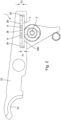
- FIG. 2 a clamp arm 20 of the clamping device 1 is shown again in a detailed representation.
- the rigid wear plate 5 is arranged, which has a thickness d 1 .
- the thickness of the wear plate 5 corresponds approximately to the distance d 2 between the rigid wear plate 5 and the material of the clamp arm 20, which defines the recess 28. Accordingly, the wear plate 5 can move within the recess 28 by a maximum distance d 2 from the control cam 3.
- a limitation is imposed here by the pressure pieces 6, since complete compression of these pressure pieces 6 is not possible.
- FIG 3 is the one in Figure 2
- the part of the clamping device 1 shown is shown again in a first position A, in which the wear plate 5 rests directly against the control cam 3 and also against the retaining lugs 280 of the recess. Accordingly, the rigid wear plate 5 is in a defined position, and the force exerted by the control cam 3 on the wear plate 5 does not exceed the force exerted by the pressure pieces 6, so that there is no compression of the pressure pieces 6.
- FIG 3 the clamping device 1 is shown in a second position B, in which the holding area 22 has been moved slightly further outwards, and a corresponding compression of the pressure piece 6 has taken place.
- the rigid wear plate 5 is thus moved against the preload applied by the pressure pieces 6 in order to move the holding area 22 of the clamping arm 20 outwards into position B against the elastic preload by the pressure pieces 6.
- the two enlarged sections A and B show once again the behavior of the rigid wear plate 5 when a force is applied that leads to compression of the pressure pieces 6.
- control section 26 of the clamp arm 20 can also be designed to be elastic, so that the force applied to the rigid wear plate 5 by means of the The forces applied by the control cam 3 can then still be transferred elastically to the clamping arm 20.
Landscapes
- Engineering & Computer Science (AREA)
- Mechanical Engineering (AREA)
- Dovetailed Work, And Nailing Machines And Stapling Machines For Wood (AREA)
- Specific Conveyance Elements (AREA)
- Filling Of Jars Or Cans And Processes For Cleaning And Sealing Jars (AREA)
Description
- Die vorliegende Erfindung betrifft eine Klammervorrichtung zum Halten eines Behälters in einer Behälterbehandlungsanlage, insbesondere zum Halten einer Flasche in einer Getränkeabfüllanlage.
- Es ist bekannt, in Getränkeabfüllanlagen die jeweils zu befüllenden Behälter beziehungsweise bereits befüllte Behälter mittels Klammervorrichtungen durch die einzelnen Behandlungsstationen der Behälterbehandlungsvorrichtung zu transportieren. Dabei sind unterschiedliche Klammervorrichtungen bekannt, welche die jeweiligen zu behandelnden Behälter auf unterschiedliche Art und Weise halten.
- So sind beispielsweise passive Klammervorrichtungen bekannt, welche lediglich durch das Einschieben des jeweiligen Behälters in die Klammervorrichtung elastisch vorgespannt werden und dann den Behälter halten.
- Weiterhin bekannt sind aktive Klammervorrichtungen, bei welchen ein Öffnen und Schließen der jeweiligen Halteabschnitte der Klammervorrichtung mittels eines Aktuators aktiv durchgeführt wird. Solche aktiven Klammervorrichtungen dienen insbesondere dazu, eine sichere und schonende Übernahme der jeweiligen Behälter von einer vorhergehenden Klammervorrichtung zu ermöglichen oder eine ebenso sichere und behälterschonende Übergabe der Behälter an eine nachfolgende Klammervorrichtung zu gewährleisten. Insbesondere kann durch das aktive Öffnen und Schließen der jeweiligen Klammervorrichtung eine erhöhte Reibung an dem jeweiligen Behälter, welche beispielsweise zu einem Verkratzen des Behälters führen könnte, vermieden werden und andererseits kann eine vorgegebene Haltekraft beziehungsweise Klemmkraft eingestellt werden, welche innerhalb eines vorgegebenen Toleranzbereichs der Behälterdimension eingehalten werden kann.
- Aus der
EP 0 939 044 A1 (sieheFigur 3 ) ist eine Klammervorrichtung zum Halten eines Behälters in einer Behälterbehandlungsanlage bekannt. Die Klammervorrichtung umfasst zwei Klammerarme mit jeweils einem Halteabschnitt zur Anlage an den zu haltenden Behälter und mit jeweils einem Steuerabschnitt, auf welchen ein Steuernocken zum Bewegen der Halteabschnitte in eine Öffnungsposition und/oder in eine Schließposition wirkt, wobei an dem Steuerabschnitt eine Blattfeder angeordnet ist, auf welche der Steuernocken wirkt, und die Blattfeder in einer am Steuerabschnitt vorgesehenen Ausnehmung des Klammerarms angeordnet, an dem Steuerabschnitt gelagert und über eine Haltenase in der Ausnehmung gehalten ist. - Die
EP 0 795 500 A2 beschreibt einen Transportstern für Gefäße mit einem drehbaren Grundkörper und mehreren an dessen Umfang schwenkbar gelagerten Greifarmen in Form von Doppelhebeln, an deren radial nach außen weisenden Enden Greifflächen für die Gefäße und an deren radial nach innen weisenden Enden Gegenflächen für beweglich im Grundkörper gelagerte Spreizkörper ausgebildet sind. Die Greifarme bestehen aus mindestens zwei gelenkig miteinander verbundenen Teilstücken, von denen mindestens eines die Greiffläche und ein anderes die Gegenfläche trägt. Die Gegenflächen für die Spreizkörper sind an lösbar an den zugehörigen Teilstücken der Greifarme befestigten Einsätzen aus verschleißfestem Material ausgebildet. - Die
DE 10 2005 014 838 A1 beschreibt eine Klammer zum Halten von Gefäßen. DieDE 299 15 927 U1 beschreibt einen Flaschengreifer. - Ausgehend von dem bekannten Stand der Technik ist es eine Aufgabe der vorliegenden Erfindung, eine Klammervorrichtung zum Halten eines Behälters in einer Behälterbehandlungsanlage anzugeben, welche ein verbessertes Halteverhalten aufweist.
- Diese Aufgabe wird durch eine Klammervorrichtung mit den Merkmalen des Anspruchs 1 gelöst. Vorteilhafte Weiterbildungen ergeben sich aus den Unteransprüchen, der vorliegenden Beschreibung sowie den Figuren.
- Entsprechend wird eine Klammervorrichtung zum Halten eines Behälters in einer Behälterbehandlungsanlage vorgeschlagen, die zwei Klammerarme mit jeweils einem Halteabschnitt zur Anlage an den zu haltenden Behälter umfasst, wobei die Klammerarme jeweils einen Steuerabschnitt, auf welchen ein Steuernocken zum Bewegen der Halteabschnitte in eine Öffnungsposition und/oder in eine Schließposition wirkt, aufweisen. Erfindungsgemäß ist an dem Steuerabschnitt eine starre Verschleißplatte angeordnet, auf welche der Steuernocken wirkt.
- Dadurch, dass der Steuerabschnitt eine starre Verschleißplatte zur Aufnahme der vom Steuernocken ausgeübten Kräfte aufweist, kann das Verschleißverhalten der Klammervorrichtung und damit das Verschleißverhalten des Steuerabschnitts verbessert werden. Damit kann eine erhöhte Standzeit der Klammervorrichtung erreicht werden, so dass über einen längeren Zeitraum hinweg ein störungsfreier Betrieb der Klammervorrichtung ermöglicht wird.
- Weiterhin kann mittels der starren Verschleißplatte erreicht werden, dass die Wahrscheinlichkeit für einen Defekt des Steuerabschnitts reduziert beziehungsweise vermieden werden kann.
- Unter "starr" wird in diesem Zusammenhang verstanden, dass die Verschleißplatte beim Auftreten der von dem Steuernocken auf die Klammervorrichtung beziehungsweise auf den Steuerabschnitt der Klammervorrichtung aufgebrachten Kräfte keine beziehungsweise keine relevante Verformung erfährt, sondern - im Falle einer elastischen Vorspannung der starren Verschleißplatte - die Kräfte direkt an die elastischen Vorspannelemente übertragen werden.
- Die starre Verschleißplatte ist in einer am Steuerabschnitt vorgesehenen Ausnehmung des Klammerarms angeordnet. Damit ergibt sich eine effiziente Konstruktion des Klammerarms, die dennoch zu einem verbesserten Verhalten der Klammervorrichtung führt.
- Dabei ist die starre Verschleißplatte über eine Haltenase, die bevorzugt einstückig mit dem Klammerarm ausgebildet ist, in der Ausnehmung gehalten.
- Ferner ist die starre Verschleißplatte schwimmend an dem Steuerabschnitt gelagert, bevorzugt mittels einer Halterung, eines Haltebolzens oder eines Formschlusselements.
- Durch die schwimmende Lagerung wird eine Beweglichkeit der starren Verschleißplatte relativ zu dem Klammerarm in Reaktion auf die durch den Steuernocken aufgebrachten Kräfte zu ermöglicht. Durch die schwimmende Lagerung kann die starre Verschleißplatte entsprechend der von dem Steuernocken aufgebrachten Kraft folgen, und mittels der Vorspannung entsprechend ein sanftes Aufbringen dieser Kraft über die Klammerarme auf den Halteabschnitt ein sanftes und gleichzeitig zuverlässiges Halten von Behältern ermöglichen.
- Die starre Verschleißplatte kann bevorzugt verschwenkbar und/oder verschiebbar an dem Steuerabschnitt gelagert sein, bevorzugt um ein Ende der Verschleißplatte herum verschwenkbar und/oder verschiebbar.
- Entsprechend kann die starre Verschleißplatte auch an einer Position am Steuerabschnitt und/oder in der Ausnehmung eingespannt sein, so dass die starre Verschleißplatte entsprechend um dieser Einspannung herum eine Bewegung ausführen kann.
- Bevorzugt ist die starre Verschleißplatte an dem Steuerabschnitt - beispielsweise in der Ausnehmung - elastisch gelagert, bevorzugt mittels eines elastischen Vorspannelements, eines Druckstücks, einer Feder, eines Magneten und/oder eines Elastomers.
- Die starre Verschleißplatte kann auf die Steuernocke zu vorgespannt sein.
- Mittels der elastischen Lagerung der starren Verschleißplatte kann zum einen ein sanftes Betätigen der Klammervorrichtung mittels der Steuernocke erreicht werden, und zum anderen können über die elastische Lagerung Toleranzen in der Behältergröße ausgeglichen werden, so dass entsprechend ein Halten von Behältern innerhalb eines bestimmten Toleranzbereiches sicher möglich ist. Dies ermöglicht auch in bestimmten Grenzen das sichere Halten von falsch gegriffenen Behältern.
- In einer Alternative zur Bereitstellung eines Druckstücks kann der Steuerabschnitt des Klammerarms formelastisch ausgebildet sein. Dadurch kann trotz der starren Ausbildung der Verschleißplatte eine elastische Aufnahme der vom Steuernocken über die Verschleißplatte auf den Klammerarm aufgebrachten Kraft erreicht werden.
- Um eine besonders standfeste Ausbildung der Klammervorrichtung zu erreichen, ist das Material der starren Verschleißplatte bevorzugt härter, als das Material des Klammerarms. Die starre Verschleißplatte kann aus einem Material ausgebildet sein, das eine höhere Verschleißresistenz aufweist, als das Material, aus dem der übrige Klammerarm ausgebildet ist. Auf diese Weise kann zum einen der Kammerarm so gestaltet werden, dass er die Anforderungen an die Dauerhaltbarkeit, das Gewicht, die Kosten sowie die Abreinigbarkeit beziehungsweise Sterilisierbarkeit erfüllt, auf der anderen Seite kann über die starre Verschleißplatte ein dediziertes Verschleißteil bereitgestellt werden, welches separat ausgetauscht werden kann, so dass im Falle einer erhöhten Abnutzung des Steuerabschnitts lediglich die starre Verschleißplatte ausgetauscht zu werden braucht, nicht hingegen der gesamte Klammerarm.
- Die starre Verschleißplatte kann aus Metall, bevorzugt Edelstahl, besonders bevorzugt V4A-Edelstahl, ausgebildet sein und ein Steuernocken kann vorgesehen sein, welcher im Bereich seiner die starre Verschleißplatte kontaktierenden Kontaktflächen aus einem Kunststoffmaterial, bevorzugt einem PEEK-Material, ausgebildet ist. Unter PEEK-Material wird hier ein Polyetheretherketon Material verstanden.
- In einer Alternative kann die starre Verschleißplatte aus einem PEEK Material ausgebildet sein und ein Steuernocken vorgesehen sein, welcher im Bereich seiner die starre Verschleißplatte kontaktierenden Kontaktflächen aus einem Metall, bevorzugt Edelstahl, besonders bevorzugt V4A-Edelstahl, ausgebildet sein.
- Bevorzugt ist jeder Klammerarm an einer Verschwenkachse verschwenkbar gelagert. Dabei ist besonders bevorzugt eine Vorspannvorrichtung zwischen dem Halteabschnitt und der Verschwenkachse vorgesehen, welche die Halteabschnitte voneinander fort vorspannt, wobei die Vorspannvorrichtung bevorzugt durch eine Feder, ein Elastomer oder einen oder mehrere Magnete ausgebildet ist.
- Als Material für die starre Verschleißplatte kann beispielsweise PEEK oder V4A-Stahl vorgesehen werden. Die starre Verschleißplatte hat bevorzugt eine Materialdicke, welche entsprechend die starren Eigenschaften der starren Verschleißplatte ermöglicht.
- Es kann ein einziges elastisches Vorspannelement vorgesehen sein, das sich über einen bestimmten Bereich zwischen der starren Verschleißplatte und dem Steuerabschnitt des Klammerarms erstreckt.
- Es können aber auch mehrere elastische Vorspannelemente vorgesehen sein, welche die elastische Vorspannung der starren Verschleißplatte gegenüber der Ausnehmung des Steuerabschnitts bereitstellen. Über die Ausbildung der elastischen Elemente sowie deren geometrische Verteilung entlang der Länge beziehungsweise entlang der Fläche der starren Verschleißplatte können entsprechend die elastischen Eigenschaften sowie die Verschließeigenschaften der Klammervorrichtung justiert werden. In einer bevorzugten Ausprägung sind die elastischen Vorspannelemente durch ein silikonartiges Elastomer mit einer Härte von ca. 40-60° Shore A vorgesehen. Die elastischen Vorspannelemente können auch jeweils in Form einer Feder, eines Druckstücks und/oder eines oderer mehrerer Magneten beziehungsweise Kombinationen dieser Elemente ausgebildet sein.
- Bevorzugte weitere Ausführungsformen der Erfindung werden durch die nachfolgende Beschreibung der Figuren näher erläutert. Dabei zeigen:
- Figur 1
- eine schematische Draufsicht auf eine Klammervorrichtung in einem ersten Ausführungsbeispiel,
- Figur 2
- eine schematische Draufsicht auf einen Teilbereich der Klammervorrichtung, wobei nur einer der Klammerarme sowie eine Steuernocke gezeigt ist, und
- Figur 3
- eine schematische Darstellung unterschiedlicher Klammerarmpositionen bei fest positioniertem Steuernocken aufgrund einer elastischen Lagerung der starren Verschleißplatte.
- Im Folgenden werden bevorzugte Ausführungsbeispiele anhand der Figuren beschrieben. Dabei werden gleiche, ähnliche oder gleichwirkende Elemente in den unterschiedlichen Figuren mit identischen Bezugszeichen versehen, und auf eine wiederholte Beschreibung dieser Elemente wird teilweise verzichtet, um Redundanzen zu vermeiden.
- In
Figur 1 ist schematisch in einer Draufsicht eine Klammervorrichtung 1 zum Halten eines hier nicht gezeigten Behälters in einer Behälterbehandlungsanlage gezeigt. Die Klammervorrichtung 1 ist insbesondere vorgesehen zum Halten von Flaschen in einer Getränkeabfüllanlage bei deren Transport durch die unterschiedlichen Behandlungsstationen der Getränkeabfüllanlage oder zum Halten während des Transports von einer Behandlungsstation zu einer nachfolgenden Behandlungsstation. - Die Klammervorrichtung 1 umfasst zwei Klammerarme 20, welche jeweils einen Halteabschnitt 22 aufweisen, der zur Anlage an den jeweils zu haltenden Behälter vorgesehen ist. Die Halteabschnitte 22 greifen dabei beispielsweise im Halsbereich einer in einer Getränkeabfüllanlage zu befüllenden Flasche an, um die Flasche in die entsprechende Behandlungsposition zu transportieren.
- Die Klammerarme 20 sind jeweils an einer Schwenkachse 24 gelagert und um diese herum verschwenkbar, um ein Öffnen und Schließen der Klammervorrichtung 1 zu ermöglichen. Entsprechend werden die Halteabschnitte 22 durch das Verschwenken der Klammerarme 20 in eine Öffnungsposition oder eine Schließposition bewegt, wobei in der Öffnungsposition ein zu haltender Behälter zwischen die Halteabschnitte 22 gebracht werden kann und in der Schließposition die Halteabschnitte 22 in feste Anlage mit dem Behälter gebracht sind, um diesen zu halten. Damit wird eine aktive Anlage der Halteabschnitte 22 an den jeweils zu haltenden Behälter erreicht.
- Ein Steuerabschnitt 26 ist in jedem Klammerarm 20 vorgesehen, welcher mit einem Steuernocken 3 in Kontakt tritt, um eine aktive Bewegung der Klammerarme 20 zu erreichen und insbesondere um ein aktives Verschwenken der Klammerarme 20 um die Schwenkachsen 24 herum zu ermöglichen.
- Der Steuernocken 3 wird dabei entsprechend dem vorgegebenen Transportweg des jeweils zu haltenden Behälters angesteuert, so dass ein Öffnen der Klammervorrichtung 1 durch eine entsprechende Rotationsstellung des Steuernockens 3 erreicht werden kann, genauso wie ein aktives Schließen der Klammervorrichtung 1 und insbesondere ein Zusammenführen der Halteabschnitte 22 der beiden Klammerarme 20 derart, dass ein zu haltender Behälter zwischen den Halteabschnitten 22 gehalten ist.
- In dem in
Figur 1 gezeigten Ausführungsbeispiel wird über den Steuernocken 3 eine vom Steuernocken 3 in radialer Richtung aufgebrachte Kraft auf den Steuerabschnitt 26 übertragen, so dass sich entsprechend eine Verschwenkbewegung um die zwischen dem Steuerabschnitt 26 und dem Halteabschnitt 22 liegende Schwenkachse 24 ergibt, welche in Schließrichtung der Klammervorrichtung 1 wirkt und die Halteabschnitte 22 in die Schließposition bewegt. - Um in einer anderen Position des Steuernockens 3, in welcher dieser keine Kraft auf den Steuerabschnitt 26 auswirkt, ein selbstständiges und definiertes Öffnen der Klammervorrichtung 1 zu ermöglichen, ist eine Vorspannvorrichtung 4 vorgesehen, welche zwischen dem Halteabschnitt 22 und der Verschwenkachse 24 angeordnet ist und welche die beiden Klammerarme 20 in die Öffnungsposition auseinandertreibt. Entsprechend sind die Klammerarme 20 über die Vorspannvorrichtung 4 stets in die Öffnungsposition vorgespannt. Erst durch eine aktive Betätigung des Steuernockens 3 und dem Aufbringen einer entsprechenden Schließkraft auf den Steuerabschnitt 26 können die Halteabschnitte 22 dann entsprechend entgegen der Vorspannung der Vorspannvorrichtung 4 in die Schließstellung gebracht werden.
- Die Vorspannvorrichtung 4 ist in dem gezeigten Ausführungsbeispiel in Form einer Feder vorgesehen. Die Vorspannvorrichtung 4 kann aber auch beispielsweise in Form eines Magneten, zweier sich gegenseitig abstoßender Magnete oder durch ein Elastomer ausgebildet sein.
- In einem alternativen Ausführungsbeispiel kann die Schwenkachse 24 auch in einer anderen Position relativ zum Halteabschnitt 22 und zum Steuernocken 3 vorgesehen sein. Insbesondere ist es auch denkbar, die Halteabschnitte 22 und den Steuernocken 3 auf der gleichen Seite bezüglich der Schwenkachse 24 vorzusehen. Entsprechend wird durch eine Betätigung des Steuernocken 3 eine Kraft auf den Klammerarm 20 ausgeübt, welche die Halteabschnitte 22 dann in die Öffnungsposition bewegt.
- Erfindungsgemäß ist im Klammerarm 20 im Bereich des Steuerabschnitts 26 eine starre Verschleißplatte 5 aufgenommen. In der in
Figur 1 gezeigten Ausführungsform wird die starre Verschleißplatte 5 in direkten Kontakt mit dem Steuernocken 3 gebracht, um entsprechend die Kraft des Steuernockens 3 über die starre Verschleißplatte 5 auf den Steuerabschnitt 26 des Klammerarms 20 zu übertragen. - Die starre Verschleißplatte 5 ist im gezeigten Ausführungsbeispiel in Form einer 2-4 mm starken V2A-Edelstahlplatte ausgebildet. Die Bereiche des Steuernockens 3, welche mit der Verschleißplatte 5 in Kontakt kommen, sind bevorzugt aus einem PEEK-Material ausgebildet, so dass sicher eine besonders verschleißarme Paarung an Materialien ergibt. Unter PEEK-Material wird hier ein Polyetheretherketon Material verstanden.
- Alternativ kann beispielsweise auch die Verschleißplatte 5 aus dem PEEK-Material ausgebildet sein und der Steuernocken 3 beziehungsweise die mit der Verschleißplatte 5 in Kontakt kommenden Bereiche des Steuernockens 3 beispielsweise durch V4A-Stahl ausgebildet sein.
- Erfindungsgemäß ist die starre Verschleißplatte 5 in einer im Steuerabschnitt 26 vorgesehenen Ausnehmung 28 des Klammerarms 20 vorgesehen.
- Die starre Verschleißplatte 5 ist in der Ausnehmung 28 erfindungsgemäß schwimmend gelagert. Entsprechend kann die Verschleißplatte 5 sich zumindest in einer Richtung innerhalb der Ausnehmung 28 bewegen, welche der Kraftwirkungsrichtung des Steuernockens 3 entspricht, wenn dieser mit der starren Verschleißplatte 5 in Kontakt gebracht wird.
- Die Ausnehmung 28 ist entsprechend bevorzugt so ausgestaltet, dass der zwischen der Verschleißplatte 5 und dem die Ausnehmung 28 begrenzenden Material des Klammerarms 20 ausgebildete Spalt beispielsweise der Materialstärke der Verschleißplatte 5 entspricht.
- Um ein Herausfallen der Verschleißplatte 5 in Richtung auf den Steuernocken 3 zu zu verhindern, ist die Ausnehmung 28 in dem Klammerarm 20 über Haltenasen 280 so ausgebildet, dass die starre Verschleißplatte 5 trotz ihrer schwimmenden Lagerung in der Ausnehmung 28 in dieser Ausnehmung 28 verbleibt, unabhängig von der jeweiligen Positionierung der Klammervorrichtung 1. Die starre Verschleißplatte 5 wird in dem gezeigten Ausführungsbeispiel weiterhin mittels zweier Haltebolzen 29 in der Ausnehmung 28 in Position gehalten. Damit wird die starre Verschleißplatte 5 in der Ausnehmung 28 in Richtung auf den Steuernocken 3 zu mittels der Haltenasen 280 am Herausfallen gehindert und in einer Ebene senkrecht dazu durch die Haltebolzen 29 an einem Herausfallen gehindert.
- Über die Halterung mittels der Haltebolzen 29 und die Haltenasen 280 ist die starre Verschleißplatte 5 in der Ausnehmung 28 schwimmend gehalten beziehungsweise gelagert. Die starre Verschleißplatte 5 kann damit sowohl verschwenkt als auch verschoben werden. Eine Veschiebung der starren Verschleißplatte 5 kann dabei beispielsweise entlang der Haltebolzen 29 erreicht werden. Eine Verschwenkung der starren Verschleißplatte 5 kann beispielsweise um eines der in der Längserstreckung des Haltearms 20 ausgebildeten Enden der starren Verschleißplatte 5 ausgeführt werden.
- Um einen Austausch der starren Verschleißplatte 5 zu ermöglichen ist in dem gezeigten Ausführungsbeispiel einer der Haltebolzen 29 entfernbar, so dass die starre Verschleißplatte 5 entfernt werden kann und durch eine neue starre Verschleißplatte 5 ersetzt werden kann.
- Die starre Verschleißplatte 5 wird im gezeigten Ausführungsbeispiel eines oder mehrere Druckstücke 6 auf den Steuernocken 3 zu vorgespannt. Die Druckstücke 6 drücken die starre Verschleißplatte 5 damit auch gegen die Haltenasen 280 der Ausnehmung 28 derart, dass im entspannten Zustand der Klammervorrichtung 1, also wenn der Steuernocken 3 keine Kraft auf die starre Verschleißplatte 5 ausübt, die starre Verschleißplatte 5 an den Haltenasen 280 anliegt, so dass sich entsprechend ein Spalt zwischen der starren Verschleißplatte 5 und dem die Ausnehmung 28 begrenzenden Material des Haltearms 20 ausbildet.
- Das Druckstück 6 beziehungsweise die Druckstücke 6 sind bevorzugt aus einem elastischen Material ausgebildet, beispielsweise einem Elastomermaterial. Bei dem Elastomermaterial des Druckstücks 6 kann es sich beispielsweise um ein Silikon-basiertes Elastomermaterial mit einer Härte von 40-60° Shore A handeln. Alternativ oder zusätzlich kann auch auf jede andere bekannte Weise eine elastische Vorspannung mittels eines elastischen Vorspannelements auf die starre Verschleißplatte 5 in Richtung auf den Steuernocken 3 zu aufgebracht werden, beispielsweise mittels einer Feder oder mittels eines Magneten.
- Entsprechend kann die von dem Steuernocken 3 auf die starre Verschleißplatte 5 aufgebrachte Kraft beim Schließen der Klammervorrichtung 1 sanft auf die Klammerarme 20 im Steuerabschnitt 26 übertragen werden. Insbesondere werden hier Kraftspitzen über die elastische Vorspannung abgefangen.
- Je nach Anforderung können ein einzelnes elastisches Vorspannelement oder zwei, drei oder eine Mehrzahl an elastischen Vorspannelementen vorgesehen sein. Über die Auswahl der elastischen Vorspannelemente kann die Charakteristik des Schließvorgangs beim Betätigen des Steuernockens 3 eingestellt werden - insbesondere über die jeweilige Härte des elastischen Vorspannelements.
- Weiterhin ist es möglich, durch eine Kombination unterschiedlicher elastischer Vorspannelemente die Charakteristik über die Verschließbewegung hinweg zu variieren. Ist beispielsweise das elastische Vorspannelement, das beim anfänglichen Kontakt des Steuernockens 3 mit der starren Verschleißplatte 5 unter dem Kontaktpunkt liegt, weicher als das daneben liegende elastische Vorspannelement, das erst später unter dem Kontaktpunkt liegt, so kann ein besonders weicher Ansatz beim ersten Anlegen der Halteabschnitte 22 an den jeweiligen zu haltenden Behälter erreicht werden, wobei darauf hin dann die ausgeübte Haltekraft dann ansteigt.
- Weiterhin ermöglicht es das Bereitstellen des oder der Druckstücke 6, dass die über die Halteabschnitte 22 auf den jeweils zu haltenden Behälter aufgebrachte Kraft (innerhalb eines Toleranzbereichs) unabhängig von den Maßen des gegriffenen Behälters ist.
- In
Figur 2 ist noch einmal ein Klammerarm 20 der Klammervorrichtung 1 in einer Detaildarstellung gezeigt. - Im Bereich des Steuerabschnitts 26 ist wiederum die starre Verschleißplatte 5 angeordnet, welche eine Dicke d1 aufweist. Die Dicke der Verschleißplatte 5 entspricht in dem gezeigten Ausführungsbeispiel in etwa dem Abstand d2 zwischen der starren Verschleißplatte 5 und dem Material des Klammerarms 20, welches die Ausnehmung 28 definiert. Entsprechend kann sich die Verschleißplatte 5 innerhalb der Ausnehmung 28 um maximal den Abstand d2 von dem Steuernocken 3 fort bewegen. Hier ist jedoch eine Begrenzung durch die Druckstücke 6 vorgegeben, da eine vollständige Kompression dieser Druckstücke 6 nicht möglich ist.
- In
Figur 3 ist der inFigur 2 gezeigte Teil der Klammervorrichtung 1 noch einmal in einer ersten Position A gezeigt, in welcher die Verschleißplatte 5 direkt an dem Steuernocken 3 und auch an den Haltenasen 280 der Ausnehmung anliegt. Entsprechend ist die starre Verschleißplatte 5 in einer definierten Position und die Kraft, welche von dem Steuernocken 3 auf die Verschleißplatte 5 ausgeübt wird, überschreitet nicht die Kraft, welche von den Druckstücken 6 ausgeübt wird, so dass eine Kompression der Druckstücke 6 nicht vorliegt. - In
Figur 3 ist die Klammervorrichtung 1 in einer zweiten Position B gezeigt, in welcher der Haltebereich 22 etwas weiter nach außen bewegt ist, und entsprechend eine Kompression des Druckstücks 6 stattgefunden hat. Die starre Verschleißplatte 5 ist damit entgegen der durch die Druckstücke 6 aufgebrachten Vorspannung bewegt, um auf diese Weise entgegen der elastischen Vorspannung durch die Druckstücke 6 den Haltebereich 22 des Klammerarms 20 entsprechend in die Position B nach außen zu bewegen. Hieraus ergibt sich entsprechend die erweiterte Öffnung, welche um einen Abstand D weiter geöffnet wurde, und welche es ermöglicht, bei einer vorgegebenen Stellung des Steuernockens 3 das Halten eines Behälters mit einem erweiterten Durchmesser ebenfalls zu ermöglichen. - Die beiden Ausschnittsvergrößerungen A und B zeigen noch einmal das Verhalten der starren Verschleißplatte 5 beim Aufbringen einer Kraft, die zu einer Kompression der Druckstücke 6 führt.
- Auf diese Weise können entsprechend leicht abweichende Radien oder auch Fehlgriffe, bei denen die Halteabschnitte 22 nicht genau am vorgesehenen Ort des Behälters angreifen, kompensiert werden.
- In einer Alternative kann anstelle der Druckstücke auch der Steuerabschnitt 26 des Klammerarms 20 formelastisch ausgebildet sein, so dass die auf die starre Verschleißplatte 5 mittels des Steuernockens 3 aufgebrachten Kräfte dann dennoch elastisch auf den Klemmarm 20 übergeben werden können.
-
- 1
- Klammervorrichtung
- 20
- Klammerarm
- 22
- Halteabschnitt
- 24
- Schwenkachse
- 26
- Steuerabschnitt
- 28
- Ausnehmung
- 280
- Haltenase
- 29
- Haltebolzen
- 3
- Steuernocken
- 4
- Vorspannvorrichtung
- 5
- starre Verschleißplatte
- 6
- elastisches Druckstück
- d1
- Dicke der starren Verschleißplatte
- d2
- Tiefe des Spalts
- D
- erweiterter Öffnungswinkel
Claims (12)
- Klammervorrichtung (1) zum Halten eines Behälters in einer Behälterbehandlungsanlage, umfassend zwei Klammerarme (20) mit jeweils einem Halteabschnitt (22) zur Anlage an den zu haltenden Behälter und mit jeweils einem Steuerabschnitt (26), auf welchen ein Steuernocken (3) zum Bewegen der Halteabschnitte (22) in eine Öffnungsposition und/oder in eine Schließposition wirkt, wobeian dem Steuerabschnitt (26) eine starre Verschleißplatte (5) angeordnet ist, auf welche der Steuernocken (3) wirkt, unddie starre Verschleißplatte (5) in einer am Steuerabschnitt (26) vorgesehenen Ausnehmung (28) des Klammerarms (20) angeordnet, schwimmend an dem Steuerabschnitt (26) gelagert und über eine Haltenase (280) in der Ausnehmung (28) gehalten ist.
- Klammervorrichtung (1) gemäß Anspruch 1, dadurch gekennzeichnet, dass die Haltenase (280) einstückig mit dem Klammerarm (20) ausgebildet ist.
- Klammervorrichtung (1) gemäß einem der vorstehenden Ansprüche, dadurch gekennzeichnet, dass die starre Verschleißplatte (5) mittels einer Halterung, eines Haltebolzens (29) oder eines Formschlusselements schwimmend an dem Steuerabschnitt (26) gelagert ist.
- Klammervorrichtung (1) gemäß Anspruch 1, dadurch gekennzeichnet, dass die starre Verschleißplatte (5) verschwenkbar und/oder verschiebbar an dem Steuerabschnitt (26) gelagert ist, bevorzugt um ein Ende der Verschleißplatte (5) herum verschwenkbar und/oder verschiebbar.
- Klammervorrichtung (1) gemäß einem der vorstehenden Ansprüche, dadurch gekennzeichnet, dass die starre Verschleißplatte (5) an dem Steuerabschnitt (26) elastisch gelagert ist, bevorzugt mittels elastischen Vorspannelements, eines Druckstücks (6), einer Feder, eines Magneten und/oder eines Elastomers.
- Klammervorrichtung (1) gemäß einem der vorstehenden Ansprüche, dadurch gekennzeichnet, dass die starre Verschleißplatte (5) an dem Steuerabschnitt (26) auf die Steuernocke (3) zu vorgespannt ist.
- Klammervorrichtung (1) gemäß einem der vorstehenden Ansprüche, dadurch gekennzeichnet, dass der Steuerabschnitt (26) des Klammerarms (20) formelastisch ausgebildet ist.
- Klammervorrichtung (1) gemäß einem der vorstehenden Ansprüche, dadurch gekennzeichnet, dass das Material der starren Verschleißplatte (5) härter ist, als das Material des Klammerarms (20).
- Klammervorrichtung (1) gemäß einem der vorstehenden Ansprüche, dadurch gekennzeichnet, dass die starre Verschleißplatte (5) aus Metall, bevorzugt Edelstahl, besonders bevorzugt V4A-Edelstahl, ausgebildet ist und ein Steuernocken (3) vorgesehen ist, welcher im Bereich seiner die starre Verschleißplatte (5) kontaktierenden Kontaktflächen aus einem PEEK-Material ausgebildet ist.
- Klammervorrichtung (1) gemäß einem der Ansprüche 1 bis 9, dadurch gekennzeichnet, dass die starre Verschleißplatte (5) aus einem PEEK-Material ausgebildet ist und ein Steuernocken (3) vorgesehen ist, welcher im Bereich seiner die starre Verschleißplatte (5) kontaktierenden Kontaktflächen aus einem Metall, bevorzugt Edelstahl, besonders bevorzugt V4A-Edelstahl, ausgebildet ist.
- Klammervorrichtung (1) gemäß einem der vorstehenden Ansprüche, dadurch gekennzeichnet, dass jeder Klammerarm (20) an einer Verschwenkachse (24) verschwenkbar gelagert ist.
- Klammervorrichtung (1) gemäß Anspruch 11, dadurch gekennzeichnet, dass eine Vorspannvorrichtung (4) zwischen dem Halteabschnitt (22) und der Verschwenkachse (24) vorgesehen ist, welche die Halteabschnitte (22) voneinander fort vorspannt, wobei die Vorspannvorrichtung (4) bevorzugt durch eine Feder, ein Elastomer oder Magnete ausgebildet ist.
Applications Claiming Priority (2)
| Application Number | Priority Date | Filing Date | Title |
|---|---|---|---|
| DE102017114158.8A DE102017114158A1 (de) | 2017-06-26 | 2017-06-26 | Klammervorrichtung zum Halten eines Behälters in einer Behälterbehandlungsanlage |
| PCT/EP2018/067066 WO2019002267A1 (de) | 2017-06-26 | 2018-06-26 | Klammervorrichtung zum halten eines behälters in einer behälterbehandlungsanlage |
Publications (3)
| Publication Number | Publication Date |
|---|---|
| EP3645431A1 EP3645431A1 (de) | 2020-05-06 |
| EP3645431B1 true EP3645431B1 (de) | 2025-06-18 |
| EP3645431C0 EP3645431C0 (de) | 2025-06-18 |
Family
ID=62748993
Family Applications (1)
| Application Number | Title | Priority Date | Filing Date |
|---|---|---|---|
| EP18734208.4A Active EP3645431B1 (de) | 2017-06-26 | 2018-06-26 | Klammervorrichtung zum halten eines behälters in einer behälterbehandlungsanlage |
Country Status (4)
| Country | Link |
|---|---|
| EP (1) | EP3645431B1 (de) |
| CN (2) | CN110891885A (de) |
| DE (1) | DE102017114158A1 (de) |
| WO (1) | WO2019002267A1 (de) |
Families Citing this family (2)
| Publication number | Priority date | Publication date | Assignee | Title |
|---|---|---|---|---|
| CN112047095A (zh) * | 2020-07-31 | 2020-12-08 | 南京昱晟机器人科技有限公司 | 一种基于小型工件自动化生产用多维度自限位式抓取装置 |
| DE102021131002A1 (de) * | 2021-11-25 | 2023-05-25 | Krones Aktiengesellschaft | Steuernocken für eine Klammervorrichtung und Klammervorrichtung zum Halten eines Behälters |
Family Cites Families (6)
| Publication number | Priority date | Publication date | Assignee | Title |
|---|---|---|---|---|
| DE19542337A1 (de) * | 1995-11-14 | 1997-05-15 | Hermann Kronseder | Transportstern für Gefäße |
| EP0795500B1 (de) * | 1996-03-13 | 2002-11-13 | Kronseder, Hermann, Dr.-Ing. E.h. | Transportstern für Gefässe |
| DE19808058A1 (de) | 1998-02-26 | 1999-09-02 | Kronseder | Flaschengreifer |
| DE29915927U1 (de) * | 1999-09-10 | 2000-02-17 | KRONES AG, 93073 Neutraubling | Flaschengreifer |
| DE102005014838A1 (de) * | 2005-03-30 | 2006-10-05 | Krones Ag | Klammer zum Halten von Gefäßen |
| CN201665436U (zh) * | 2009-11-13 | 2010-12-08 | 南京乐惠轻工装备制造有限公司 | 夹具和星轮组件 |
-
2017
- 2017-06-26 DE DE102017114158.8A patent/DE102017114158A1/de active Pending
-
2018
- 2018-06-26 EP EP18734208.4A patent/EP3645431B1/de active Active
- 2018-06-26 CN CN201880047005.6A patent/CN110891885A/zh active Pending
- 2018-06-26 CN CN202511410115.2A patent/CN121376890A/zh active Pending
- 2018-06-26 WO PCT/EP2018/067066 patent/WO2019002267A1/de not_active Ceased
Also Published As
| Publication number | Publication date |
|---|---|
| EP3645431A1 (de) | 2020-05-06 |
| WO2019002267A1 (de) | 2019-01-03 |
| CN110891885A (zh) | 2020-03-17 |
| EP3645431C0 (de) | 2025-06-18 |
| CN121376890A (zh) | 2026-01-23 |
| DE102017114158A1 (de) | 2018-12-27 |
Similar Documents
| Publication | Publication Date | Title |
|---|---|---|
| EP0939044B1 (de) | Flaschengreifer | |
| EP2858793B1 (de) | Greiferanordnung | |
| EP1868746B1 (de) | Klammer zum halten von gefässen | |
| EP3702318B1 (de) | Verschliesserkopf zum verschliessen eines behälters mit einem behälterverschluss | |
| EP3286118B1 (de) | Behältergreifer sowie transportvorrichtung zum transportieren von behältern | |
| EP1930259A1 (de) | Greifer, insbesondere für Gefässe | |
| EP3907161B1 (de) | Passive klammervorrichtung | |
| EP4186831A1 (de) | Klammervorrichtung zum halten eines behälters | |
| EP3964461B1 (de) | Klammervorrichtung zum halten eines behälters und behälterbehandlungsvorrichtung | |
| EP2882673B1 (de) | Behältergreifer sowie transportelement mit derartigen behältergreifern | |
| DE102011117622A1 (de) | Magnetisch sperrbare Flaschenklammer | |
| EP3912939A1 (de) | Klammervorrichtung und behälterbehandlungsvorrichtung | |
| EP3645431B1 (de) | Klammervorrichtung zum halten eines behälters in einer behälterbehandlungsanlage | |
| DE102012017048A1 (de) | Behandlungs- und Transportvorrichtung mit selbstadaptiven Greifelementen | |
| EP4186832B1 (de) | Steuernocken für eine klammervorrichtung und klammervorrichtung zum halten eines behälters | |
| EP4183725A1 (de) | Vorrichtung und verfahren zum transportieren von behältnissen mit rollengestütztem stellmechanismus für greifklammern | |
| DE102017108926B4 (de) | Vorrichtung zum Transportieren von Behältern | |
| EP3708523B1 (de) | Passive klammervorrichtung, einteilige passive klammer und behälterbehandlungsvorrichtung | |
| DE202009005811U1 (de) | Crimpwerkzeug | |
| EP4079665B1 (de) | Vorrichtung zum greifen eines gegenstands und eine wenigstens eine solche vorrichtung umfassende transportvorrichtung | |
| EP2559640B1 (de) | Greifer für Flaschen sowie Bearbeitungsmaschine mit einer Anzahl von Greifern und Verfahren zur Handhabung von Flaschen | |
| DE102017108928B4 (de) | Behältergreifer | |
| DE10059951B4 (de) | Übergabestern zum Transportieren von Gefäßen | |
| DE10059950B4 (de) | Übergabestern zum Transportieren von Gefäßen | |
| DE102023103860A1 (de) | Klammervorrichtung zum Halten eines Behälters und Behälterbehandlungsvorrichtung |
Legal Events
| Date | Code | Title | Description |
|---|---|---|---|
| STAA | Information on the status of an ep patent application or granted ep patent |
Free format text: STATUS: UNKNOWN |
|
| STAA | Information on the status of an ep patent application or granted ep patent |
Free format text: STATUS: THE INTERNATIONAL PUBLICATION HAS BEEN MADE |
|
| PUAI | Public reference made under article 153(3) epc to a published international application that has entered the european phase |
Free format text: ORIGINAL CODE: 0009012 |
|
| STAA | Information on the status of an ep patent application or granted ep patent |
Free format text: STATUS: REQUEST FOR EXAMINATION WAS MADE |
|
| 17P | Request for examination filed |
Effective date: 20200127 |
|
| AK | Designated contracting states |
Kind code of ref document: A1 Designated state(s): AL AT BE BG CH CY CZ DE DK EE ES FI FR GB GR HR HU IE IS IT LI LT LU LV MC MK MT NL NO PL PT RO RS SE SI SK SM TR |
|
| AX | Request for extension of the european patent |
Extension state: BA ME |
|
| DAV | Request for validation of the european patent (deleted) | ||
| DAX | Request for extension of the european patent (deleted) | ||
| GRAP | Despatch of communication of intention to grant a patent |
Free format text: ORIGINAL CODE: EPIDOSNIGR1 |
|
| STAA | Information on the status of an ep patent application or granted ep patent |
Free format text: STATUS: GRANT OF PATENT IS INTENDED |
|
| INTG | Intention to grant announced |
Effective date: 20221117 |
|
| GRAJ | Information related to disapproval of communication of intention to grant by the applicant or resumption of examination proceedings by the epo deleted |
Free format text: ORIGINAL CODE: EPIDOSDIGR1 |
|
| STAA | Information on the status of an ep patent application or granted ep patent |
Free format text: STATUS: REQUEST FOR EXAMINATION WAS MADE |
|
| STAA | Information on the status of an ep patent application or granted ep patent |
Free format text: STATUS: EXAMINATION IS IN PROGRESS |
|
| INTC | Intention to grant announced (deleted) | ||
| 17Q | First examination report despatched |
Effective date: 20230403 |
|
| P01 | Opt-out of the competence of the unified patent court (upc) registered |
Effective date: 20230523 |
|
| GRAP | Despatch of communication of intention to grant a patent |
Free format text: ORIGINAL CODE: EPIDOSNIGR1 |
|
| STAA | Information on the status of an ep patent application or granted ep patent |
Free format text: STATUS: GRANT OF PATENT IS INTENDED |
|
| INTG | Intention to grant announced |
Effective date: 20240820 |
|
| GRAJ | Information related to disapproval of communication of intention to grant by the applicant or resumption of examination proceedings by the epo deleted |
Free format text: ORIGINAL CODE: EPIDOSDIGR1 |
|
| STAA | Information on the status of an ep patent application or granted ep patent |
Free format text: STATUS: EXAMINATION IS IN PROGRESS |
|
| GRAP | Despatch of communication of intention to grant a patent |
Free format text: ORIGINAL CODE: EPIDOSNIGR1 |
|
| INTC | Intention to grant announced (deleted) | ||
| STAA | Information on the status of an ep patent application or granted ep patent |
Free format text: STATUS: GRANT OF PATENT IS INTENDED |
|
| INTG | Intention to grant announced |
Effective date: 20250116 |
|
| GRAS | Grant fee paid |
Free format text: ORIGINAL CODE: EPIDOSNIGR3 |
|
| GRAA | (expected) grant |
Free format text: ORIGINAL CODE: 0009210 |
|
| STAA | Information on the status of an ep patent application or granted ep patent |
Free format text: STATUS: THE PATENT HAS BEEN GRANTED |
|
| AK | Designated contracting states |
Kind code of ref document: B1 Designated state(s): AL AT BE BG CH CY CZ DE DK EE ES FI FR GB GR HR HU IE IS IT LI LT LU LV MC MK MT NL NO PL PT RO RS SE SI SK SM TR |
|
| REG | Reference to a national code |
Ref country code: GB Ref legal event code: FG4D Free format text: NOT ENGLISH |
|
| REG | Reference to a national code |
Ref country code: CH Ref legal event code: EP |
|
| REG | Reference to a national code |
Ref country code: DE Ref legal event code: R096 Ref document number: 502018015883 Country of ref document: DE |
|
| REG | Reference to a national code |
Ref country code: CH Ref legal event code: EP |
|
| REG | Reference to a national code |
Ref country code: IE Ref legal event code: FG4D Free format text: LANGUAGE OF EP DOCUMENT: GERMAN |
|
| U01 | Request for unitary effect filed |
Effective date: 20250708 |
|
| U07 | Unitary effect registered |
Designated state(s): AT BE BG DE DK EE FI FR IT LT LU LV MT NL PT RO SE SI Effective date: 20250714 |
|
| U20 | Renewal fee for the european patent with unitary effect paid |
Year of fee payment: 8 Effective date: 20250716 |
|
| PG25 | Lapsed in a contracting state [announced via postgrant information from national office to epo] |
Ref country code: NO Free format text: LAPSE BECAUSE OF FAILURE TO SUBMIT A TRANSLATION OF THE DESCRIPTION OR TO PAY THE FEE WITHIN THE PRESCRIBED TIME-LIMIT Effective date: 20250918 Ref country code: GR Free format text: LAPSE BECAUSE OF FAILURE TO SUBMIT A TRANSLATION OF THE DESCRIPTION OR TO PAY THE FEE WITHIN THE PRESCRIBED TIME-LIMIT Effective date: 20250919 |
|
| PG25 | Lapsed in a contracting state [announced via postgrant information from national office to epo] |
Ref country code: HR Free format text: LAPSE BECAUSE OF FAILURE TO SUBMIT A TRANSLATION OF THE DESCRIPTION OR TO PAY THE FEE WITHIN THE PRESCRIBED TIME-LIMIT Effective date: 20250618 |
|
| PG25 | Lapsed in a contracting state [announced via postgrant information from national office to epo] |
Ref country code: RS Free format text: LAPSE BECAUSE OF FAILURE TO SUBMIT A TRANSLATION OF THE DESCRIPTION OR TO PAY THE FEE WITHIN THE PRESCRIBED TIME-LIMIT Effective date: 20250918 |
|
| PG25 | Lapsed in a contracting state [announced via postgrant information from national office to epo] |
Ref country code: IS Free format text: LAPSE BECAUSE OF FAILURE TO SUBMIT A TRANSLATION OF THE DESCRIPTION OR TO PAY THE FEE WITHIN THE PRESCRIBED TIME-LIMIT Effective date: 20251018 |
|
| PG25 | Lapsed in a contracting state [announced via postgrant information from national office to epo] |
Ref country code: SM Free format text: LAPSE BECAUSE OF FAILURE TO SUBMIT A TRANSLATION OF THE DESCRIPTION OR TO PAY THE FEE WITHIN THE PRESCRIBED TIME-LIMIT Effective date: 20250618 |
|
| PG25 | Lapsed in a contracting state [announced via postgrant information from national office to epo] |
Ref country code: CZ Free format text: LAPSE BECAUSE OF FAILURE TO SUBMIT A TRANSLATION OF THE DESCRIPTION OR TO PAY THE FEE WITHIN THE PRESCRIBED TIME-LIMIT Effective date: 20250618 |
|
| PG25 | Lapsed in a contracting state [announced via postgrant information from national office to epo] |
Ref country code: PL Free format text: LAPSE BECAUSE OF FAILURE TO SUBMIT A TRANSLATION OF THE DESCRIPTION OR TO PAY THE FEE WITHIN THE PRESCRIBED TIME-LIMIT Effective date: 20250618 |
|
| PG25 | Lapsed in a contracting state [announced via postgrant information from national office to epo] |
Ref country code: SK Free format text: LAPSE BECAUSE OF FAILURE TO SUBMIT A TRANSLATION OF THE DESCRIPTION OR TO PAY THE FEE WITHIN THE PRESCRIBED TIME-LIMIT Effective date: 20250618 |
|
| REG | Reference to a national code |
Ref country code: CH Ref legal event code: H13 Free format text: ST27 STATUS EVENT CODE: U-0-0-H10-H13 (AS PROVIDED BY THE NATIONAL OFFICE) Effective date: 20260127 |
|
| PG25 | Lapsed in a contracting state [announced via postgrant information from national office to epo] |
Ref country code: ES Free format text: LAPSE BECAUSE OF FAILURE TO SUBMIT A TRANSLATION OF THE DESCRIPTION OR TO PAY THE FEE WITHIN THE PRESCRIBED TIME-LIMIT Effective date: 20250618 |
|
| PG25 | Lapsed in a contracting state [announced via postgrant information from national office to epo] |
Ref country code: MC Free format text: LAPSE BECAUSE OF FAILURE TO SUBMIT A TRANSLATION OF THE DESCRIPTION OR TO PAY THE FEE WITHIN THE PRESCRIBED TIME-LIMIT Effective date: 20250618 |
|
| PG25 | Lapsed in a contracting state [announced via postgrant information from national office to epo] |
Ref country code: IE Free format text: LAPSE BECAUSE OF NON-PAYMENT OF DUE FEES Effective date: 20250626 |
|
| PG25 | Lapsed in a contracting state [announced via postgrant information from national office to epo] |
Ref country code: CH Free format text: LAPSE BECAUSE OF NON-PAYMENT OF DUE FEES Effective date: 20250630 |
|
| PLBE | No opposition filed within time limit |
Free format text: ORIGINAL CODE: 0009261 |
|
| STAA | Information on the status of an ep patent application or granted ep patent |
Free format text: STATUS: NO OPPOSITION FILED WITHIN TIME LIMIT |
|
| REG | Reference to a national code |
Ref country code: CH Ref legal event code: L10 Free format text: ST27 STATUS EVENT CODE: U-0-0-L10-L00 (AS PROVIDED BY THE NATIONAL OFFICE) Effective date: 20260430 |