EP3645449B1 - Magnetorheologischer aktuator für einer befüllungseinheit einer getränkeabfüllanlage - Google Patents
Magnetorheologischer aktuator für einer befüllungseinheit einer getränkeabfüllanlage Download PDFInfo
- Publication number
- EP3645449B1 EP3645449B1 EP18734556.6A EP18734556A EP3645449B1 EP 3645449 B1 EP3645449 B1 EP 3645449B1 EP 18734556 A EP18734556 A EP 18734556A EP 3645449 B1 EP3645449 B1 EP 3645449B1
- Authority
- EP
- European Patent Office
- Prior art keywords
- actuator
- actuator element
- electromagnet
- valve membrane
- fluid path
- Prior art date
- Legal status (The legal status is an assumption and is not a legal conclusion. Google has not performed a legal analysis and makes no representation as to the accuracy of the status listed.)
- Active
Links
Images





Classifications
-
- B—PERFORMING OPERATIONS; TRANSPORTING
- B67—OPENING, CLOSING OR CLEANING BOTTLES, JARS OR SIMILAR CONTAINERS; LIQUID HANDLING
- B67C—CLEANING, FILLING WITH LIQUIDS OR SEMILIQUIDS, OR EMPTYING, OF BOTTLES, JARS, CANS, CASKS, BARRELS, OR SIMILAR CONTAINERS, NOT OTHERWISE PROVIDED FOR; FUNNELS
- B67C3/00—Bottling liquids or semiliquids; Filling jars or cans with liquids or semiliquids using bottling or like apparatus; Filling casks or barrels with liquids or semiliquids
- B67C3/02—Bottling liquids or semiliquids; Filling jars or cans with liquids or semiliquids using bottling or like apparatus
- B67C3/22—Details
- B67C3/26—Filling-heads; Means for engaging filling-heads with bottle necks
-
- B—PERFORMING OPERATIONS; TRANSPORTING
- B67—OPENING, CLOSING OR CLEANING BOTTLES, JARS OR SIMILAR CONTAINERS; LIQUID HANDLING
- B67C—CLEANING, FILLING WITH LIQUIDS OR SEMILIQUIDS, OR EMPTYING, OF BOTTLES, JARS, CANS, CASKS, BARRELS, OR SIMILAR CONTAINERS, NOT OTHERWISE PROVIDED FOR; FUNNELS
- B67C3/00—Bottling liquids or semiliquids; Filling jars or cans with liquids or semiliquids using bottling or like apparatus; Filling casks or barrels with liquids or semiliquids
- B67C3/02—Bottling liquids or semiliquids; Filling jars or cans with liquids or semiliquids using bottling or like apparatus
- B67C3/22—Details
- B67C3/28—Flow-control devices, e.g. using valves
-
- F—MECHANICAL ENGINEERING; LIGHTING; HEATING; WEAPONS; BLASTING
- F16—ENGINEERING ELEMENTS AND UNITS; GENERAL MEASURES FOR PRODUCING AND MAINTAINING EFFECTIVE FUNCTIONING OF MACHINES OR INSTALLATIONS; THERMAL INSULATION IN GENERAL
- F16K—VALVES; TAPS; COCKS; ACTUATING-FLOATS; DEVICES FOR VENTING OR AERATING
- F16K31/00—Actuating devices; Operating means; Releasing devices
- F16K31/02—Actuating devices; Operating means; Releasing devices electric; magnetic
- F16K31/06—Actuating devices; Operating means; Releasing devices electric; magnetic using a magnet, e.g. diaphragm valves, cutting off by means of a liquid
- F16K31/0603—Multiple-way valves
- F16K31/0641—Multiple-way valves the valve member being a diaphragm
-
- F—MECHANICAL ENGINEERING; LIGHTING; HEATING; WEAPONS; BLASTING
- F16—ENGINEERING ELEMENTS AND UNITS; GENERAL MEASURES FOR PRODUCING AND MAINTAINING EFFECTIVE FUNCTIONING OF MACHINES OR INSTALLATIONS; THERMAL INSULATION IN GENERAL
- F16K—VALVES; TAPS; COCKS; ACTUATING-FLOATS; DEVICES FOR VENTING OR AERATING
- F16K31/00—Actuating devices; Operating means; Releasing devices
- F16K31/02—Actuating devices; Operating means; Releasing devices electric; magnetic
- F16K31/06—Actuating devices; Operating means; Releasing devices electric; magnetic using a magnet, e.g. diaphragm valves, cutting off by means of a liquid
- F16K31/0644—One-way valve
- F16K31/0672—One-way valve the valve member being a diaphragm
Definitions
- the present invention relates to an actuator for controlling the fluid paths of a filling unit for a beverage filling plant, a filling unit for a beverage filling plant and a beverage filling plant.
- Beverage filling systems are used for the industrial filling of beverages, both so-called soft drinks and alcoholic beverages.
- the filling process requires a large number of valves that feed the desired amount of beverage into the container to be filled.
- the containers are first evacuated before filling to displace the oxygen present in them and then flooded with carbon dioxide at a pressure of around 2 bar, for example.
- the opening and closing of the valves is controlled by actuators that generate the required movement with the necessary force. Electro-pneumatic actuators are currently used in particular for this purpose.
- an electro-magnetic valve for a filling device of a beverage filling plant from the EN 10 2012 105 374 A1 known.
- a filling machine for filling containers is, for example, from the DE 203 19 619 U1 and from the EN 10 2010 032 398 A1 known.
- An actuator for controlling at least one fluid path of a filling unit for a beverage filling plant has become known.
- This comprises at least one control unit and at least one actuator element, by means of which an actuating force can be provided, wherein by means of the control unit at least one first control signal and at least one second control signal can be provided and wherein the actuator element consists of a material which, depending on a first control signal, assumes a first extension in which the actuator element assumes a first rest position, and which, depending on the second control signal, assumes an extension in which the actuator element assumes a second setting position.
- the WO 2017/148614 A1 further discloses that the material of the actuator element can be or can comprise a magnetorheological elastomer and that the magnetorheological elastomer can be activated by means of an electromagnet.
- an actuator for controlling at least one fluid path of a filling unit for a beverage filling system is provided with at least one control unit and with at least one actuator element, by means of which an actuating force can be provided.
- the actuator element has a seat part that is fixed to a seat and a closing part that can be moved relative to the seat.
- At least one first control signal and at least one second control signal can be provided by means of the control unit, wherein the actuator element consists of a material that, depending on the first control signal, assumes a first shape in which the actuator element assumes a first rest position, and that, depending on the second control signal, assumes a shape in which the actuator element assumes a second actuating position.
- the material of the actuator element is or comprises a magnetorheological elastomer.
- the actuator has at least one electromagnet, wherein the actuator element is located in the variable magnetic field of the electromagnet and the magnetic field of the electromagnet can be changed by the first and second control signals.
- the actuator element is a fluid valve membrane and the closing part is a component of the fluid valve membrane.
- Magnetorheological elastomers are, for example, composites of magnetizable particles such as iron in an elastomer matrix such as silicone or natural rubber.
- the MRE body deforms or moves in the magnetic field and performs an actuator movement.
- the material returns to its original shape or position when the magnetic field is switched off.
- the movement can be carried out within a few milliseconds, provided the magnetic field can be built up quickly enough.
- the actuator element In its first position, the actuator element can actuate a fluid path of the filling unit in a sealing manner, and the actuator element can actuate the fluid path in a non-sealing manner in its second position. This allows simple control of the fluid path of the filling unit, including the corresponding functional link, to be achieved. A rapid back and forth movement of the closing part is guaranteed due to the use of an MRE in a magnetic field.
- the invention is based on the basic idea of providing an actuator for controlling at least one fluid path of a filling unit for a beverage bottling plant with an actuator element which, due to its material properties, can be controlled so easily that, due to a change in the shape of the actuator element, it can be brought into at least two defined positions, here a rest position and an actuating position.
- a rest position it can be provided, for example, that the fluid path is open.
- the fluid path is blocked in the actuating position.
- the actuating force exerted by the actuator element in this context here, for example, in the actuating position, is sufficient to seal the fluid path.
- the rest position is a position in which the fluid path is blocked and the actuating position is a position in which the fluid path is open.
- the actuating position is a position in which the fluid path is open.
- NORMALLY OPEN configuration In the case described above, one can speak of a "normally open” actuator (NORMALLY OPEN configuration).
- the fluid path can in particular be a gas path of a filling unit. However, it is also conceivable that it is a fluid path for conveying the beverage to be filled.
- the actuator element is a disc, in which in particular the edge is the fixed seat part.
- the valve paths of common valves can be easily closed or opened.
- the actuator element is a fluid valve membrane.
- actuating force is at least approximately 200-400 N, in particular approximately 350-370 N, preferably approximately 360 N. This magnitude of an actuating force has proven to be particularly advantageous in order to provide a secure closure of the fluid paths at the working pressures that prevail in the filling unit and in the beverage filling system.
- the material of the actuator element comprises an electrorheological liquid or a gel.
- an expansion of the liquid or gel can be achieved by applying a voltage.
- a further advantageous development of the invention provides that the actuator element is connected to one end of a spring - compression spring or tension spring - and the other end is firmly connected to the actuator. This makes it easy to achieve NORMALLY OPEN and NORMALLY CLOSED configurations.
- a further advantageous development of the invention provides that the actuator has, in addition to the first actuator element, a further actuator element which is designed in the same way as the first actuator element and is arranged parallel to it. This opens up further applications, in particular with double valves, both fluid paths can be opened and closed easily - even independently of one another.
- a further advantageous development of the invention provides that the two actuator elements rest against each other in their respective rest positions. Such an arrangement is more compact than a design in which the two actuator elements are spaced apart from each other.
- a further advantageous development of the invention provides that the actuator comprises a double valve. This means that the invention can be used in other areas.
- the actuator has two electromagnets, the first electromagnet being arranged above and the second electromagnet being arranged below the actuator element. This makes it possible to It is necessary to attach a spring or other additional part to the actuator element, which returns it to its original shape.
- the two actuators can be controlled (almost) independently of each other.
- the material of the actuator element comprises one or more of the following materials or that the actuator has a corresponding element: a magnetorheological fluid or gel, a dielectric elastomer, a thermal shape memory alloy, a magnetic shape memory alloy; a piezoceramic, a piezoceramic stack, a piezo pressure sensor.
- actuator elements are connected in series.
- the actuator elements can at least partially form a bellows structure.
- several similar actuator elements i.e. with a similar or identical selection of materials, are used.
- the stroke of the actuator can be in the range of a few millimeters, whereby a stroke of more than 1 mm, especially in the range between 5 and 10 mm, has proven to be advantageous. In principle, however, strokes of more than 10 mm are also conceivable, especially when controlling fluid paths for liquids.
- the actuator element in its first form, can define a switching position in which the fluid valve membrane, as which the actuator element is designed, is actuated in a sealing manner in the at least one fluid path of the filling unit, and in its second form the actuator element can define a switching position in which the fluid valve membrane is not actuated in a sealing manner.
- the combination of actuator and fluid valve membrane and the corresponding functional linkage can achieve simple control of the fluid path of the filling unit.
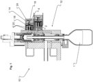
- Fig.1 shows a schematic sectional view in side view of a beverage filling system 10 according to the invention, here partially shown by a filling unit 12 with an actuator 14 for controlling at least one fluid path 20.
- the actuator 14 is arranged together with a fluid valve membrane 16 in a housing part 18 of the filling unit 12.
- At least one first control signal and at least one second control signal can be provided by means of the control unit.
- the actuator 14 further comprises an actuator element 24.
- the actuator element 24 consists at least partially of a material which, depending on a first control signal from the control unit, assumes a first shape in which the actuator element 24 assumes a first rest position, and which, depending on a second control signal, assumes a shape in which the actuator element 24 assumes a second actuating position.
- the ring-like element located at the free end of the actuator 14 can be provided as a damping element.
- the actuating force can be in the order of at least approx. 200-400 N, in particular approx. 350-370 N, preferably approx. 360 N.
- the fluid path 20 can, for example, have a dimension of approximately 24 mm.
- Working pressures can be in the range between 3 and 10 bar, in particular 8 bar or, if the membrane area of the fluid valve membrane 16 is adjusted, approximately 6 bar.
- a further characteristic of the switching times is that three switching cycles can be carried out within a maximum period of 1.2 s.
- the function of the actuator 14 is to release the fluid valve membrane 16 in at least a first switching position and to actuate it in at least a second switching position such that it seals off a fluid path 20 of the filling unit 12.
- the actuator element 24 actuates a first switching position in which the fluid valve membrane 16 is sealingly actuated in the fluid path 20 of the filling unit 12 (closed position) and in the second extension, a second switching position in which the fluid valve membrane 16 is not actuated (open position).
- the actuator 14 can be provided with a NORMALLY OPEN design in which the actuator 14 does not actuate the fluid valve membrane 16 in the non-actuated state.
- the actuator 14 has a NORMALLY CLOSED configuration, which means that the actuator 14, in the non-actuated state, ensures that the fluid valve membrane 16 is actuated in a sealing manner and seals the fluid path 20 of the filling unit 12.
- actuators 14 with sometimes very different actuator elements 24, 24' are shown. Identical or equivalent parts are designated in the figures with the same reference numerals.
- the actuator elements 24 of all embodiments consist of or contain MRE material.
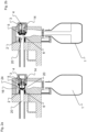
- FIG. 2a and 2b is a schematic representation of a first embodiment of an actuator 14 according to the invention with an actuator element 24 whose fluid valve membrane 16 is in two positions: in Fig. 2a with closed fluid path 20 and in Fig. 2b with fluid path 20 open.
- the fluid valve membrane 16 is made entirely of an MRE and is disk-shaped. It has a seat part 5 on its edge, which is firmly anchored in the actuator 14. The inner part of this fluid valve membrane 16 is designed as a closing part 5, which can change its shape and is shown in two positions.
- a tappet 4 is mounted, which pushes the fluid valve membrane 16 by means of a spring 3 to the right, into the Fig. 2b shown position in which the fluid path 20 is open.
- NORMALLY OPEN There is a NORMALLY OPEN version.
- a NORMALLY CLOSED version is also possible; the specialist knows how to do this.
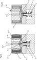
- Fig. 3a and 3b is a schematic view of a second embodiment of an actuator 14 not according to the invention, which is significantly different from that of the first embodiment of the Fig. 2a and 2b is constructed.
- the actuator element 24 made of MRE is not designed as a fluid valve membrane 16. It has a ring shape, the outer edge of which is firmly connected to the actuator 14 as a seat part 5.
- a mandrel 8 is arranged centrally in the fluid path 20 and is surrounded by a bellows 11.
- the bellows 11 can fold in the longitudinal direction of the mandrel 8.
- On the outer surface of the bellows 11, the inner edge 25 of the ring is fixed to a movable part 9 designed as a closing part 6, which divides the bellows 11 into an upper and a lower part.
- a first electromagnet 2 is arranged above the actuator element 24 and a second electromagnet 7 is arranged below the actuator element 24.
- the actuator element 24 is moved downwards in its closing part 6 into its Fig. 3b shown position. In this position, an annular gap is formed between the closure part 13 of the bellows 11 and the mandrel 8, which releases the fluid path 20.
- the movable part 9 from material containing MRE (or consisting entirely of MRE) instead of the ring-shaped actuator element 24. Then the Fig. 3a and 3b The annular actuator element 24 shown can be completely omitted since the movable part 9 takes over the function of the actuator element 24.
- Fig. 4a and 4b is a schematic view of a third embodiment of an actuator 14 not according to the invention with two actuator elements 24, 24' instead of only a single actuator element 24 according to the Fig. 3a and 3b In the following, only the differences to the example of the Fig. 3a and 3b received.
- Each of the two actuator elements 24, 24' is constructed and connected to the bellows 11 via the movable part 9 - on which the closing part 6 is formed - like the single actuator element 24 of the previous embodiment.
- the Electromagnets 2, 7 are designed in such a way that they can produce separately adjustable field strengths. This makes it possible to set intermediate positions of the bellows 11 to the mandrel 8; in these intermediate positions - one is in Fig. 4b shown - the size of the annular gap between the closure part 13 of the bellows 11 and the mandrel 8 is different in each case. This allows the fluid path 20 to be adjusted and it is possible to use the actuator 14 as an inlet throttle.
- the bellows 11 in one or two parts, as already described for the Fig. 3a and 3b It is also possible, instead of manufacturing the actuator elements 24, 24' with MRE material, to manufacture the movable part from such a material.
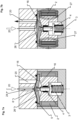
- FIG. 5a and 5b A fourth embodiment of an actuator 14 according to the invention is shown schematically, with a design that differs greatly from the two principles of the first to third embodiments explained so far.
- an electromagnet 2 is attached in a mandrel 8 - comparable to that of the Fig. 3a, 3b , 4a and 4b - an electromagnet 2 is attached. Between the mandrel 8 and the inner wall 15 of the actuator 14, an annular gap is formed, which represents the fluid path 20.
- an annular actuator element 24 is arranged on the inner wall 15 of the actuator 14. Within the inner wall 15, the actuator element 24 is connected to two Figures 5a and 5b superimposed locations are firmly connected to the actuator 14. These locations are thus the seat parts 5 of the actuator element 24.
- the closing part 6 of the actuator element 24 in a U-shape, which is designed as a fluid valve membrane 16 and consists of an MRE material.
- the electromagnet 2 When the electromagnet 2 is energized, the closing part 6 is moved towards the mandrel until it takes on a V-shape, rests against it and closes the fluid path 20. This is shown in Fig. 5a If the current of the electromagnet 2 is switched off, the closing part 6 moves back to its Fig. 5b shown position and opens the fluid path 20 again.
- FIG. 6a and 6b A fifth embodiment of an actuator 14 according to the invention is shown schematically, with a configuration which corresponds to that of the first embodiment of the Fig. 2a and 2b
- a spring 3 is used in conjunction with an electromagnet 2 to open and close the fluid path 20.
- the difference to the first embodiment is - besides the different installation direction - essentially in that the shape of the fluid path 20 and the shape of the fluid valve membrane 16 are different.
- the fluid valve membrane 16 is in the closed state of the fluid path 20 according to Fig. 6a not - seen in cross-section - quasi U-shaped, but only has a slight hat shape with an upward curvature - in the direction of the closed fluid path 20.
- the fluid path 20 is designed such that it is bent by 180° in the area of its interaction with the fluid valve membrane 16 - in the first embodiment only by 90°.
- the electromagnet 2 is energized - this is illustrated by the resulting field lines 27 - and thus the MRE material of the actuator element 24 is pulled upwards; against the restoring force of a spring 3, which acts on a tappet 4, which is centrally connected to the fluid valve membrane 16.
- the fluid path 20 is opened by removing the current from the electromagnet 2 and the restoring force of the spring 3 pushes the fluid valve membrane 16 downwards via the tappet 4 into the Fig. 6b shown position and thus opens the fluid path 20. It is a NORMAL OPEN version.
- FIG. 7a and 7b A sixth embodiment of an actuator 14 according to the invention is shown schematically, which differs from the sixth embodiment of the Fig. 6a and 6b differs essentially in two points.
- the electromagnet 2 is mounted below the fluid valve membrane 16 and a spring 3 presses in the de-energised state of the electromagnet 2 (see Fig. 7a ) the fluid valve membrane 16 upwards so that the fluid path 20 is closed.
- the electromagnet 2 is energized - this is done by the resulting field lines 27 in Fig. 7b - and thus pulls the fluid valve membrane 16 downwards against the spring force. If the current is switched off, the spring 3 pushes the tappet together with the connected fluid valve membrane 16 upwards into the starting position according to Fig. 7a .
- the closing part 6 is not formed on the fluid valve membrane 16, but on a fluid-tight additional membrane 26 connected to the fluid valve membrane 16 in its outer region.
- This additional membrane 26 consists of a flexible plastic. It is supported by the fluid valve membrane 16 made of MRE.
- Fig. 7a presses the fluid valve membrane 16 from below onto the additional membrane 26, so that its closing part 6 closes the fluid path 20.
- the fluid valve membrane 16 is energized when the Fig. 7b pulled downwards against the force of the spring 3 and thus no longer touches the additional membrane 26 in its central area, where the closing part 6 is formed.
- the fluid path 20 is thus opened here.
- FIG. 8a and 8b is a schematic view of a seventh embodiment of an actuator 14 according to the invention, which is a combination of the two embodiments according to the Figures 6a, 6b and 7a, 7b
- a first electromagnet 2 and a second electromagnet 7 are used, which are arranged above and below the fluid valve membrane 16.
- the first electromagnet 2 When the first electromagnet 2 is energized, the fluid valve membrane 16 is pulled upwards and closes the fluid path 20 (see Fig. 8a ).
- the first electromagnet 2 is switched off and the second electromagnet 7 is energized. This pulls the fluid valve membrane 16 downwards and opens the fluid path 20.
- This embodiment therefore does not require a spring 3 to return the fluid valve membrane 16 to its starting position.
- the field lines 27 that arise when the respective electromagnet 2, 7 is energized are shown in each case.
- Fig. 9a and 9b is a schematic view of an eighth embodiment of an actuator 14 not according to the invention.
- this is an actuator 14 which is similar to that of the sixth embodiment of the Fig. 6a and 6b is similar: It is a NORMAL OPEN version.
- the restoring force for opening the fluid path 20 (see Fig. 9b ) is provided by a movable part 9 in the form of a plastic part 19 - e.g. made of PTFE.
- the plastic part 19 is centrally connected to the fluid valve membrane 16 and firmly anchored at its outer edge in the housing part 18.
- the electromagnet 2 When the electromagnet 2 is energized - this is achieved by the field lines 27 that are created in Fig. 9a - the closing part 6 of the actuator element 24 - which has no fluid valve membrane 16 - is moved upwards against the inherent tension of the plastic part 19.
- the closed state of the fluid path 20 (see Fig. 9a ) and the upper middle part of the plastic part 19 is designed as a closing part 6 so that it closes the fluid path 20.
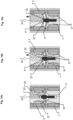
- FIG. 10a to 10c A ninth embodiment of an actuator 14 not according to the invention is shown schematically, which follows a similar principle to that of the actuators 14 shown in the Fig. 3a, 3b and 4a, 4b
- Two electromagnets 2, 7 are used, which move the closing part 6 of the actuator element 24 between a lower position (see Fig. 10a ) and an upper position (see Fig. 10c ).
- a head 22 Centrally connected to the closing part 6 is a head 22 which has a seat surface 23 in its upper end region which can interact with a conical surface of the fluid path 20.
- Fig. 10a only the first electromagnet 2 is energized, so that the closing part 6 is pulled upwards and the seat surface 23 of the head 22 is sealingly retracted into the fluid path 20.
- the other extreme position of the closing part 6 is in Fig. 10c shown.
- the second electromagnet 7 is energized, so that the head 22 is pulled all the way down and is in a stop position. In this position, the fluid path 20 is completely open.
- the head 22 can be held in any intermediate position by suitable selection of the respective field strengths of the two electromagnets 2, 7 ( Fig. 10b ).
- the head 22 is retracted more or less far into the fluid path 20 and due to the conical seat surface 23 in connection with the conical surface of the fluid path 20, an annular gap of variable size (depending on how far the head 22 is retracted into the fluid path 20) is formed between these two. This allows the flow rate to be regulated.
- the field lines 27 that arise when the respective electromagnet 2, 7 is energized are shown in each case.
- Fig. 11a and 11b is a schematic view of a tenth embodiment of an actuator 14 according to the invention with a double valve. All embodiments discussed so far had only one fluid path 20.
- two fluid paths 20, 20' are present: a first fluid path 20 above the fluid valve membrane 16 and a second fluid path 20' below it.
- the first fluid path 20 see Fig. 11a
- the second fluid path 20' see Fig. 11b
- the movement of the fluid valve membrane 16 corresponds exactly to that of the eighth embodiment of the Fig. 8a and 8b , so that in order to avoid repetition, reference is made to the statements there.
- the field lines 27 resulting from the energization of the respective electromagnet 2, 7 are shown in each case.
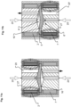
- Fig. 12a to 12c is a schematic of an eleventh embodiment of an actuator 14 according to the invention.
- a double valve is used. This is constructed in the same way as the previously described embodiment, with one difference: instead of a single fluid valve membrane 16, there are two fluid valve membranes 16, 16', which are installed directly above one another and whose seat parts 5, 5' touch one another.
- the first fluid valve membrane 16 arranged at the top opens or closes the first fluid path 20 and the second fluid valve membrane 16' arranged at the bottom opens or closes the second fluid path 20'.
- a first electromagnet 2 arranged at the top and a second electromagnet 7 arranged at the bottom are available for this purpose.
- the two fluid valve membranes 16, 16' are pulled upwards and the upwardly facing surface of the first fluid valve membrane 16 closes the first fluid path 20.
- the second fluid valve membrane 16' opens the second fluid path 20' since its downwardly facing surface is pulled upwards.
- the two fluid valve membranes 16, 16' are pulled downwards and the downward-facing surface of the second fluid valve membrane 16' closes the second fluid path 20'.
- the first fluid valve membrane 16 opens the first fluid path 20 because its upward-facing surface is pulled downwards.
- Fig. 12c a state of the double valve is shown in which both fluid paths 20, 20' are closed.
- both electromagnets 2, 7 are energized.
- the first fluid valve membrane 16 is pulled upwards and the second fluid valve membrane 16' is pulled downwards.
- the upward-facing surface of the first fluid valve membrane 16 closes the first fluid path 20
- the downward-facing surface of the second fluid valve membrane 16' closes the second fluid path 20'.
- the closing parts 6, 6' of the two fluid valve membranes 16, 16' do not touch each other; a cavity is formed between them.
- the field lines 27 that arise when the respective electromagnet 2, 7 is energized are shown in the Fig. 12a to 12c shown in each case.
Landscapes
- Engineering & Computer Science (AREA)
- General Engineering & Computer Science (AREA)
- Mechanical Engineering (AREA)
- Magnetically Actuated Valves (AREA)
Description
- Die vorliegende Erfindung betrifft einen Aktuator zur Steuerung der Fluidwege einer Befüllungseinheit für eine Getränkeabfüllanlage, eine Befüllungseinheit für eine Getränkeabfüllanlage sowie eine Getränkeabfüllanlage.
- Getränkeabfüllanlagen werden verwendet zum industriellen Abfüllen von Getränken, hierbei sowohl für sogenannte Soft-Drinks als auch alkoholische Getränke.
- Für den Abfüllvorgang sind eine Vielzahl von Ventilen notwendig, die das Getränk in der gewünschten Menge in das zu befüllende Behältnis einleiten. Außerdem werden die Behälter vor dem Befüllen zunächst ggf. evakuiert, um den darin vorhandenen Sauerstoff zu verdrängen und beispielsweise anschließend mit Kohlendioxid unter ca. 2 bar geflutet. Das Öffnen und Schließen der Ventile wird mittels Aktuatoren gesteuert, die die erforderliche Bewegung mit der nötigen Kraft erzeugen. Gegenwärtig werden hierzu insbesondere elektro-pneumatische Aktuatoren verwendet.
- Allerdings ist vorgesehen, die heute verwendeten elektro-pneumatischen Aktuatoren durch andere Aktuatoren zu ersetzen, da die Verwendung von elektro-pneumatischen Aktuatoren vergleichsweise teuer ist.
- Aus dem Stand der Technik ist beispielsweise bereits ein elektro-magnetisches Ventil für ein Füllorgan einer Getränkeabfüllanlage aus der
DE 10 2012 105 374 A1 bekannt. - Eine Füllmaschine zum Füllen von Behältern ist beispielsweise aus der
DE 203 19 619 U1 und aus derDE 10 2010 032 398 A1 bekannt. - Aus der
DE 11 2005 000 562 B4 ist es bekannt, einen Aktuator aus einem magnetorheologischen Elastomere für Dichtungen an Türen oder Türrahmen im Rahmen einer Dichtungsanordnung zu verwenden. - Aus der
WO 2017/148614 A1 ist ein Aktuator zur Steuerung wenigstens eines Fluidweges einer Befüllungseinheit für eine Getränkeabfüllanlage bekannt geworden. Dieser umfasst wenigstens eine Steuereinheit und wenigstens ein Aktuatorelement, mittels dessen eine Stellkraft bereitstellbar ist, wobei mittels der Steuereinheit wenigstens ein erstes Steuersignal und wenigstens ein zweites Steuersignal bereitstellbar ist und wobei das Aktuatorelement aus einem Material besteht, das in Abhängigkeit von einem ersten Steuersignal eine erste Ausdehnung annimmt, in der das Aktuatorelement eine erste Ruheposition einnimmt, und das in Abhängigkeit von dem zweiten Steuersignal eine Ausdehnung annimmt, in der das Aktuatorelement eine zweite Anstellposition einnimmt. DieWO 2017/148614 A1 offenbart weiterhin, dass das Material des Aktuatorelements ein magnetorheologisches Elastomer sein kann oder umfassen kann und dass das magnetorheologische Elastomer mittels eines Elektromagnets aktiviert werden kann. - Es ist die Aufgabe der vorliegenden Erfindung, einen Aktuator zur Steuerung der Fluidwege einer Befüllungseinheit für eine Getränkeabfüllanlage, eine Befüllungseinheit für eine Getränkeabfüllanlage sowie eine Getränkeabfüllanlage in vorteilhafter Weise weiterzubilden, insbesondere dahingehend, dass ein Aktuator einfacher aufgebaut, kostengünstiger herstellbar und mit langer Standzeit bereitgestellt werden kann.
- Diese Aufgabe wird erfindungsgemäß gelöst durch einen Aktuator mit den Merkmalen des Anspruchs 1. Danach ist vorgesehen, dass ein Aktuator zur Steuerung wenigstens eines Fluidweges einer Befüllungseinheit für eine Getränkeabfüllanlage mit wenigstens einer Steuereinheit und mit wenigstens einem Aktuatorelement, mittels dessen eine Stellkraft bereitstellbar ist, versehen ist. Das Aktuatorelement weist einen zu einem Sitz feststehenden Sitzteil und einen zum Sitz beweglichen Schließteil auf. Mittels der Steuereinheit ist wenigstens ein erstes Steuersignal und wenigstens ein zweites Steuersignal bereitstellbar, wobei das Aktuatorelement aus einem Material besteht, das in Abhängigkeit von dem ersten Steuersignal eine erste Form annimmt, in der das Aktuatorelement eine erste Ruheposition einnimmt, und das in Abhängigkeit von dem zweiten Steuersignal eine Form annimmt, in der das Aktuatorelement eine zweite Anstellposition einnimmt. Erfindungsgemäß ist auch vorgesehen, dass das Material des Aktuatorelements ein magnetorheologisches Elastomer ist oder umfasst. Es ist vorgesehen, dass der Aktuator mindestens einen Elektromagneten aufweist, wobei sich das Aktuatorelement in dem veränderlichen Magnetfeld des Elektromagneten befindet und das Magnetfeld des Elektromagneten durch das erste und zweite Steuersignal veränderbar ist. Ferner ist vorgesehen, dass das Aktuatorelement eine Fluidventilmembran ist und der Schließteil Bestandteil der Fluidventilmembran ist.
- Magnetorheologische Elastomere (MRE) sind beispielsweise Komposite aus magnetisierbaren Partikeln, wie Eisen in einer Elastomermatrix wie Silikon oder Naturkautschuk. Beim Anlegen eines Magnetfelds verformt sich der MRE-Körper bzw. bewegt sich in dem Magnetfeld und führt eine aktuatorische Bewegung aus. Auch hier geht das Material beim Abschalten des Magnetfelds wieder in seine anfängliche Form bzw. Position zurück. Die Bewegung kann innerhalb weniger Millisekunden ausgeführt werden, sofern das Magnetfeld schnell genug aufgebaut werden kann. Das Aktuatorelement kann in seiner ersten Position einen Fluidweg der Befüllungseinheit dichtend betätigen und das Aktuatorelement kann in seiner zweiten Position den Fluidweg nicht dichtend betätigen. Dadurch kann einschließlich der entsprechenden funktionalen Verknüpfung eine einfache Steuerung des Fluidweges der Befüllungseinheit erreicht werden. Hierbei ist eine schnelle Hin- und Herbewegung des Schließteils aufgrund der Verwendung eines MRE in einem Magnetfeld gewährleistet.
- Die Erfindung basiert auf dem Grundgedanken, einen Aktuator zur Steuerung wenigstens eines Fluidweges einer Befüllungseinheit für eine Getränkeabfüllanlage mit einem Aktuatorelement zu versehen, der aufgrund seiner Materialeigenschaften derart einfach angesteuert werden kann, dass aufgrund einer Formänderung des Aktuatorelements dieser wenigstens in zwei definierte Positionen, hier eine Ruheposition und eine Anstellposition, gebracht werden kann. In der Ruheposition kann beispielsweise vorgesehen sein, dass der Fluidweg geöffnet ist. Des Weiteren ist dann vorgesehen, dass in der Anstellposition der Fluidweg gesperrt wird. In diesem Zusammenhang ist insbesondere denkbar, dass die Stellkraft, die durch das Aktuatorelement in diesem Zusammenhang, hier beispielsweise in der Anstellposition, ausgeübt wird, ausreichend ist, um den Fluidweg dichtend zu verschließen. Grundsätzlich denkbar ist aber auch, dass die Ruheposition eine Position ist, in der der Fluidweg gesperrt ist und die Anstellposition eine Position, in der der Fluidweg geöffnet ist. In diesem Fall würde man von einem "Normally-Closed"-Aktuator (NORMAL GESCHLOSSEN Konfiguration) sprechen. Im vorstehend dargestellten Fall kann man von einem "Normally-Open"-Aktuator (NORMAL OFFEN Konfiguration) sprechen. Bei dem Fluidweg kann es sich insbesondere um einen Gasweg einer Befüllungseinheit handeln. Grundsätzlich denkbar ist aber auch, dass es sich etwa um einen Fluidweg zur Leitung des abzufüllenden Getränks handelt.
- Eine vorteilhafte Weiterbildung der Erfindung sieht vor, dass das Aktuatorelement eine Scheibe ist, bei der insbesondere der Rand der feststehende Sitzteil ist. Dadurch können die Ventilwege bei gängigen Ventilen gut geschlossen bzw. geöffnet werden. Das Aktuatorelement ist erfindungsgemäß eine Fluidventilmembran.
- Eine vorteilhafte Weiterbildung der Erfindung sieht vor, dass die Stellkraft wenigstens ca. 200-400 N, insbesondere ca. 350-370 N, vorzugsweise ca. 360 N beträgt. Diese Größenordnung einer Stellkraft hat sich als besonders vorteilhaft erwiesen, um einen sicheren Verschluss der Fluidwege bei den Arbeitsdrücken, die in der Befüllungseinheit und in der Getränkeabfüllanlage vorherrschen, bereitzustellen.
- Eine weitere vorteilhafte Weiterbildung der Erfindung sieht vor, dass das Material des Aktuatorelements eine elektrorheologische Flüssigkeit oder ein Gel umfasst. Hier kann durch Anlegen einer Spannung eine Ausdehnung der Flüssigkeit oder des Gels erreicht werden.
- Eine weitere vorteilhafte Weiterbildung der Erfindung sieht vor, dass das Aktuatorelement mit dem einen Ende einer Feder - Druckfeder oder Zugfeder - verbunden ist und deren anderen Ende fest mit dem Aktuator verbunden ist. Dadurch können in einfacher Art und Weise NORMAL OFFEN und NORMAL GESCHLOSSEN Konfigurationen erreicht werden.
- Eine weitere vorteilhafte Weiterbildung der Erfindung sieht vor, dass der Aktuator zusätzlich zu dem ersten Aktuatorelement ein weiteres Aktuatorelement aufweist, das gleich ausgebildet ist wie das erste Aktuatorelement und parallel zu diesem angeordnet ist. Dadurch sind weitere Anwendungsfälle eröffnet, insbesondere bei Doppelventilen, kann ein gutes Öffnen und Schließen beider Fluidwege - auch unabhängig voneinander - erfolgen.
- Eine weitere vorteilhafte Weiterbildung der Erfindung sieht vor, dass die beiden Aktuatorelemente in ihrer jeweiligen Ruheposition aneinander anliegen. Eine solche Anordnung baut kompakter als bei einer Ausgestaltung, bei der die beiden Aktuatorelemente voneinander beabstandet sind.
- Eine weitere vorteilhafte Weiterbildung der Erfindung sieht vor, dass der Aktuator ein Doppelventil umfasst. Damit ist die Erfindung auf weiteren Gebieten einsetzbar.
- Eine weitere vorteilhafte Weiterbildung der Erfindung sieht vor, dass der Aktuator zwei Elektromagnete aufweist, wobei der erste Elektromagnet oberhalb und der zweite Elektromagnet unterhalb des Aktuatorelements angeordnet sind. Dadurch ist es nicht nötig, eine Feder oder ein anderes Zusatzteil am Aktuatorelement anzubringen, das dieses wieder in seine erste Form zurückbringt. Darüber hinaus kann bei einer Ausgestaltung mit zwei Aktuatorelementen in einem Doppelventil eine Steuerung der beiden Aktuatoren (fast) unabhängig voneinander erfolgen.
- Darüber hinaus kann vorgesehen sein, dass das Material des Aktuatorelementes eines oder mehrere der folgenden Materialen umfasst bzw. der Aktuator ein entsprechendes Element aufweist: eine magnetorheologische Flüssigkeit oder ein solches Gel, ein dielektrisches Elastomer, eine thermische Formgedächtnislegierung, eine magnetische Formgedächtnislegierung; eine Piezokeramik, einen Piezokeramikstapel, einen Piezo-Drucksensor.
- Darüber hinaus kann vorgesehen sein, dass mehrere in Reihe geschaltete Aktuatorelemente vorgesehen sind. Insbesondere können dabei die Aktuatorelemente zumindest teilweise eine Faltenbalgstruktur ausbilden. Grundsätzlich ist denkbar, dass mehrere gleichartige Aktuatorelemente, d.h. mit gleichartiger bzw. identischer Materialauswahl verwendet werden. Grundsätzlich ist es alternativ oder zusätzlich auch möglich, mehrere Materialarten für die Aktuatorelemente, wie insbesondere vorstehend im Einzelnen aufgeführt, zu kombinieren, insbesondere im Hinblick auf die Erreichung und Einstellung entsprechender Stellkräfte, aber auch Hubwege.
- Der Hubweg des Aktuators kann im Bereich einiger Millimeter liegen, wobei sich ein Hubweg von größer 1 mm, insbesondere im Bereich zwischen 5 bis 10 mm als vorteilhaft herausgestellt hat. Grundsätzlich denkbar sind aber auch Hubwege größer 10 mm, insbesondere dann, wenn es sich um die Steuerung von Fluidwegen für Flüssigkeiten handelt.
- Das Aktuatorelement kann in seiner ersten Form eine Schaltstellung definieren, in der die Fluidventilmembran, als die das Aktuatorelement ausgebildet ist, in den wenigstens einen Fluidweg der Befüllungseinheit dichtend betätigt ist und das Aktuatorelement kann in seiner zweiten Form eine Schaltstellung definieren, in der die Fluidventilmembran nicht dichtend betätigt ist. Durch die Kombination von Aktuator und Fluidventilmembran und die entsprechende funktionale Verknüpfung kann eine einfache Steuerung des Fluidweges der Befüllungseinheit erreicht werden.
- Des Weiteren wird die Aufgabe durch eine Befüllungseinheit für eine Getränkeabfüllanlage gemäß Anspruch 9 sowie durch eine Getränkeabfüllanlage gemäß Anspruch 10 gelöst. Da diese jeweils mindestens einen erfindungsgemäßen Aktuator enthalten, ergeben sich die oben zum Aktuator schon beschriebenen Vorteile analog.
- Alle in den Unteransprüchen angegebenen Merkmale der vorteilhaften Weiterbildungen sind sowohl für sich jeweils einzeln als auch in beliebigen Kombinationen zur Erfindung gehörig.
- Weitere Einzelheiten und Vorteile der Erfindung werden anhand von in den Zeichnungen dargestellten Ausführungsbeispielen näher erläutert.
- Es zeigen:
- Fig. 1
- eine schematische Schnittdarstellung einer erfindungsgemäßen Getränkeabfüllanlage mit einer erfindungsgemäßen Befüllungseinheit sowie einen erfindungsgemäßen Aktuator;
- Fig. 2a-b
- schematische Darstellungen eines ersten Ausführungsbeispiels eines erfindungsgemäßen Aktuators;
- Fig. 3a-b
- schematische Darstellungen eines zweiten Ausführungsbeispiels eines nicht erfindungsgemäßen Aktuators;
- Fig. 4a-b
- schematische Darstellungen eines dritten Ausführungsbeispiels eines nicht erfindungsgemäßen Aktuators;
- Fig. 5a-b
- schematische Darstellungen eines vierten Ausführungsbeispiels eines erfindungsgemäßen Aktuators;
- Fig. 6a-b
- schematische Darstellungen eines fünften Ausführungsbeispiels eines erfindungsgemäßen Aktuators;
- Fig. 7a-b
- schematische Darstellungen eines sechsten Ausführungsbeispiels eines erfindungsgemäßen Aktuators;
- Fig. 8a-b
- schematische Darstellungen eines siebten Ausführungsbeispiels eines erfindungsgemäßen Aktuators;
- Fig. 9a-b
- schematische Darstellungen eines achten Ausführungsbeispiels eines nicht erfindungsgemäßen Aktuators;
- Fig. 10a-c
- schematische Darstellungen eines neunten Ausführungsbeispiels eines nicht erfindungsgemäßen Aktuators;
- Fig. 11a-b
- schematische Darstellungen eines zehnten Ausführungsbeispiels eines erfindungsgemäßen Aktuators und
- Fig. 12a-c
- schematische Darstellungen eines elften Ausführungsbeispiels eines erfindungsgemäßen Aktuators.
-
Fig. 1 zeigt eine schematische Schnittdarstellung in der Seitenansicht einer erfindungsgemäßen Getränkeabfüllanlage 10, hier teilweise dargestellt durch eine Befüllungseinheit 12 mit einem Aktuator 14 zur Steuerung wenigstens eines Fluidweges 20. - Der Aktuator 14 ist gemeinsam mit einer Fluidventilmembran 16 in einem Gehäuseteil 18 der Befüllungseinheit 12 angeordnet.
- Des Weiteren ist eine Steuereinheit (nicht gezeigt) vorgesehen. Mittels der Steuereinheit kann wenigstens ein erstes Steuersignal und wenigstens ein zweites Steuersignal bereitgestellt werden.
- Der Aktuator 14 weist ferner ein Aktuatorelement 24 auf. Das Aktuatorelement 24 besteht zumindest teilweise aus einem Material, das in Abhängigkeit von einem ersten Steuersignal der Steuereinheit eine erste Form annimmt, in der das Aktuatorelement 24 eine erste Ruheposition einnimmt, und das in Abhängigkeit von einem zweiten Steuersignal eine Form annimmt, in der das Aktuatorelement 24 eine zweite Anstellposition einnimmt. Das am freien Ende des Aktuators 14 befindliche ringartige Element kann als ein Dämpfungselement vorgesehen werden.
- Mit dem Aktuator 14 können Schaltzeiten im Bereich von ca. 40 ms in beide Richtungen ausgeführt werden.
- Denkbar ist dabei auch, dass ein Hubweg der Fluidventilmembran 16 in einem Bereich von ca. 6 mm oder auch mehr, insbesondere - beispielsweise im Zusammenhang mit Flüssigkeiten - von mehr als 10 mm möglich ist.
- Die Stellkraft kann in einer Größenordnung von wenigstens ca. 200-400 N, insbesondere ca. 350-370 N, vorzugsweise ca. 360 N liegen.
- Der Fluidweg 20 kann beispielsweise eine Abmessung von ca. 24 mm aufweisen.
- Arbeitsdrücke können im Bereich zwischen 3 bis 10 bar, insbesondere 8 bar oder bei Anpassung der Membranfläche der Fluidventilmembran 16 bei ca. 6 bar liegen.
- Bei den Schaltzeiten kann als weitere Charakteristik erreicht werden, dass drei Schaltzyklen in einem Zeitraum von höchstens 1,2 s durchgeführt werden können.
- Die Funktion des Aktuators 14 besteht darin, die Fluidventilmembran 16 in wenigstens einer ersten Schaltstellung freizugeben und in wenigstens einer zweiten Schaltstellung derart zu betätigen, dass sie einen Fluidweg 20 der Befüllungseinheit 12 dichtend verschließt.
- Das Aktuatorelement 24 betätigt in der ersten Ausdehnung eine erste Schaltstellung, in der die Fluidventilmembran 16 in dem Fluidweg 20 der Befüllungseinheit 12 dichtend betätigt ist (geschlossene Stellung) und in der zweiten Ausdehnung eine zweite Schaltstellung, in der die Fluidventilmembran 16 nicht betätigt ist (offene Stellung).
- Grundsätzlich kann vorgesehen sein, dass der Aktuator 14 eine NORMAL OFFEN Ausführung betrifft, in der der Aktuator 14 im nicht betätigten Zustand die Fluidventilmembran 16 nicht betätigt.
- Grundsätzlich kann aber auch vorgesehen sein, dass der Aktuator 14 eine NORMAL GESCHLOSSEN Konfiguration aufweist, dies bedeutet, dass der Aktuator 14 im nicht betätigten Zustand dafür sorgt, dass die Fluidventilmembran 16 dichtend betätigt ist und den Fluidweg 20 der Befüllungseinheit 12 dichtend verschließt.
- In den
Figuren 2 bis 12 werden verschiedene Ausführungsbeispiele von Aktuatoren 14 mit teilweise sehr unterschiedlichen Aktuatorelementen 24, 24' gezeigt. Gleiche oder gleichwirkende Teile sind in den Figuren mit den gleichen Bezugszeichen bezeichnet. Die Aktuatorenelemente 24 aller Ausführungsbeispiele bestehen aus oder enthalten MRE-Material. - In den
Fig. 2a und 2b ist schematisch ein erstes Ausführungsbeispiel eines erfindungsgemäßen Aktuators 14 mit einem Aktuatorelement 24, dessen Fluidventilmembran 16 sich in zwei Stellungen befindet, dargestellt: inFig. 2a bei geschlossenem Fluidweg 20 und inFig. 2b bei geöffnetem Fluidweg 20. - Die Fluidventilmembran 16 ist vollständig aus einem MRE und ist scheibenförmig ausgebildet. Sie weist an ihrem Rand einen Sitzteil 5 auf, der fest in dem Aktuator 14 verankert ist. Der innere Teil dieser Fluidventilmembran 16 ist als Schließteil 5 ausgebildet, das seine Form ändern kann und in zwei Positionen dargestellt ist.
- In der Mitte der Fluidventilmembran 16 ist ein Stößel 4 angebracht, der die Fluidventilmembran 16 mittels einer Feder 3 nach rechts, in die in
Fig. 2b dargestellten Stellung zu bewegen, in der der Fluidweg 20 geöffnet ist. - Um die in
Fig. 2a dargestellte Position zu erreichen, in der die Fluidventilmembran 16 im Bereich ihres Schließteils 6 eine Ausbuchtung aufweist, die den Fluidweg 20 schließt, wird ein Elektromagnet 2 bestromt und zieht somit das MRE-Material aus dem die Fluidventilmembran 16 besteht, gegen den Druck der Feder 3 an. Wenn der Strom im Elektromagneten 2 abgeschaltet wird, bewegt sich aufgrund der Rückstellkraft der Feder 3 der Schließteil 6 der Fluidventilmembran 16 wieder nach rechts in die inFig. 2b gezeigte Stellung und öffnet den Fluidweg 20. - Es liegt eine NORMAL OFFEN Ausführung vor. Eine NORMAL GESCHLOSSEN Ausführung ist ebenso realisierbar; der Fachmann weiß, wie er dies bewerkstelligt.
- In den
Fig. 3a und 3b ist schematisch ein zweites Ausführungsbeispiel eines nicht erfindungsgemäßen Aktuators 14, der deutlich verschieden zu demjenigen des ersten Ausführungsbeispiels derFig. 2a und 2b aufgebaut ist. - Das aus MRE bestehende Aktuatorelement 24 ist nicht als Fluidventilmembran 16 ausgebildet. Es weist eine Ringform auf, dessen äußerer Rand als Sitzteil 5 fest mit dem Aktuator 14 verbunden ist. Im Fluidweg 20 ist zentral ein Dorn 8 angeordnet, der von einem Faltenbalg 11 umgeben ist. Der Faltenbalg 11 kann sich in Längsrichtung des Dorns 8 falten. An der Außenfläche des Faltenbalgs 11 ist der innere Rand 25 des Rings an einem als Schließteil 6 ausgebildeten beweglichen Teil 9, das den Faltenbalg 11 in einen oberen und einen unteren Teil teilt, festgelegt. Oberhalb des Aktuatorelements 24 ist ein erster Elektromagnet 2 und unterhalb des Aktuatorelements 24 ist ein zweiter Elektromagnet 7 angeordnet. Anstatt den Faltenbalg 11 zweiteilig auszubilden - mit dem beweglichen Teil 9 zwischen oberem und unterem Teil -, ist es auch möglich, das bewegliche Teil 9 an der Außenfläche eines einstückigen Faltenbalgs 11 anzubringen (bspw. durch Verklebung oder andere, dem Fachmann geläufige Verbindungsmethoden). Dann ist der Schließteil 6 an der Innenfläche des Faltenbalgs 11 ausgebildet in dem Bereich, in dem das bewegliche Teil 9 mit ihm verbunden ist.
- Bei der Bestromung des ersten Elektromagneten 2 wird das MRE-Material des Aktuatorelements 24 in seinem Schließteil 6 nach oben gezogen, so dass der Faltenbalg 11 mit seinem konischen Verschlussteil 13 an dem Dorn 8 anliegt und den Fluidweg 20 verschließt.
- Wird der zweite Elektromagnet 7 bestromt, wird das Aktuatorelement 24 in seinem Schließteil 6 nach unten in seine in
Fig. 3b dargestellte Position gezogen. In dieser wird zwischen dem Verschlussteil 13 des Faltenbalgs 11 und dem Dorn 8 ein Ringspalt gebildet, der den Fluidweg 20 freigibt. - Dadurch, dass zwei Elektromagneten 2, 7 vorhanden sind, die das Aktuatorelement 24 zwischen den beiden in den
Fig. 3a und 3b dargestellten Positionen bewegt, ist keine Feder 3 nötig, um diese Bewegung zu bewirken. - Die bei der Bestromung der Elektromagnete 2, 7 entstehenden Feldlinien 27 sind in
Fig. 3a und 3b nicht dargestellt. Dasselbe gilt auch für dieFig. 4a und 4b sowie 5a. - Es sei noch erwähnt, dass es auch möglich ist, anstatt des ringförmigen Aktuatorelements 24 das bewegliche Teil 9 aus MRE enthaltendem Material (bzw. vollständig aus MRE bestehendem Material) zu fertigen. Dann kann das in den
Fig. 3a und 3b dargestellte ringförmige Aktuatorelement 24 ganz entfallen, da das bewegliche Teil 9 die Funktion des Aktuatorelements 24 übernimmt. - In den
Fig. 4a und 4b ist schematisch ein drittes Ausführungsbeispiel eines nicht erfindungsgemäßen Aktuators 14 mit zwei Aktuatorlementen 24, 24' anstatt nur einem einzigen Aktuatorelement 24 gemäß denFig. 3a und 3b . Im Folgenden wird nur auf die Unterschiede zum Ausführungsbeispiel derFig. 3a und 3b eingegangen. - Jedes der beiden Aktuatorelemente 24, 24' ist so aufgebaut und mit dem Faltenbalg 11 über das bewegliche Teil 9 - an dem der Schließteil 6 ausgebildet ist - verbunden, wie das einzige Aktuatorelement 24 des vorangegangenen Ausführungsbeispiels. Die Elektromagnete 2, 7 sind so ausgeführt, dass sie separat einstellbare Feldstärken produzieren können. Damit ist es möglich, auch Zwischenstellungen des Faltenbalgs 11 zum Dorn 8 einzustellen; in diesen Zwischenstellungen - eine ist in
Fig. 4b dargestellt - ist die Größe des Ringspalts zwischen Verschlussteil 13 des Faltenbalgs 11 und Dorn 8 jeweils unterschiedlich. Somit kann der Fluidweg 20 eingestellt werden und es ergibt sich die Möglichkeit, den Aktuator 14 als Zulaufdrossel zu nutzen. - Auch beim dritten Ausführungsbeispiel ist es möglich, den Faltenbalg 11 einteilig oder zweiteilig auszuführen, wie dies schon zu den
Fig. 3a und 3b ausgeführt wurde. Ebenso ist es möglich, anstatt die Aktuatorelemente 24, 24' mit MRE-Material zu fertigen, das bewegliche Teil aus einem solchen Material herzustellen. - In den
Fig. 5a und 5b ist schematisch ein viertes Ausführungsbeispiel eines erfindungsgemäßen Aktuators 14 dargestellt, mit einer Ausgestaltung, die stark von den beiden bisher erläuterten Prinzipien der ersten bis dritten Ausführungsbeispiele abweicht. - In einem Dorn 8 - vergleichbar demjenigen der
Fig. 3a, 3b ,4a und 4b - ist ein Elektromagnet 2 angebracht. Zwischen dem Dorn 8 und der Innenwand 15 des Aktuators 14 ist ein Ringspalt ausgebildet, der den Fluidweg 20 darstellt. Um den Fluidweg 20 - der inFig. 5b in seinem geöffneten Zustand dargestellt ist, zu schließen, ist an der Innenwand 15 des Aktuators 14 ein ringförimges Aktuatorelement 24 angeordnet. Innerhalb der Innenwand 15 ist das Aktuatorelement 24 an zwei in denFiguren 5a und 5b übereinander liegenden Stellen fest mit dem Aktuator 14 verbunden. Diese Stellen sind somit die Sitzteile 5 des Aktuatorelements 24. Dazwischen erstreckt sich - im Querschnitt gesehen - U-förmig der Schließteil 6 des Aktuatorelements 24, das als Fluidventilmembran 16 ausgebildet ist und aus einem MRE-Material besteht. Beim Bestromen des Elektromagneten 2 wird der Schließteil 6 auf den Dorn zubewegt bis er eine V-Form annimmt, an diesem anliegt und den Fluidweg 20 verschließt. Dies ist inFig. 5a dargestellt. Wird der Strom des Elektromagneten 2 abgestellt, bewegt sich der Schließteil 6 wieder in seine inFig. 5b dargestellte Position und öffnet den Fluidweg 20 wieder. - In den
Fig. 6a und 6b ist schematisch ein fünftes Ausführungsbeispiel eines erfindungsgemäßen Aktuators 14 dargestellt, mit einer Ausgestaltung, die derjenigen des ersten Ausführungsbeispiels derFig. 2a und 2b ähnlich ist. Auch hier wird eine Feder 3 in Verbindung mit einem Elektromagneten 2 zum Öffnen und Schließen des Fluidwegs 20 eingesetzt. Der Unterschied zum ersten Ausführungsbeispiel liegt - neben der unterschiedlichen Einbaurichtung - im Wesentlichen darin, dass die Form des Fluidwegs 20 und die Form der Fluidventilmembran 16 unterschiedlich sind. Die Fluidventilmembran 16 ist im geschlossenen Zustand des Fluidwegs 20 gemäßFig. 6a nicht - im Querschnitt gesehen - quasi U-förmig, sondern weist nur eine geringe Hutform mit Wölbung nach oben - in Richtung des verschlossenen Fluidwegs 20 - auf. Außerdem ist der Fluidweg 20 so ausgebildet, dass er im Bereich seiner Wechselwirkung mit der Fluidventilmembran 16 um 180° gebogen ist - im ersten Ausführungsbeispiel nur um 90°. - Zum Schließen des Fluidwegs (siehe
Fig. 6a ) wird der Elektromagnet 2 bestromt - dies wird durch die dabei entstehenden Feldlinien 27 verdeutlicht - und somit das MRE-Material des Aktuatorelements 24 nach oben gezogen; gegen die Rückstellkraft einer Feder 3, die an einem Stößel 4 angreift, der zentral mit der Fluidventilmembran 16 verbunden ist. Geöffnet wird der Fluidweg 20, indem der Strom vom Elektromagneten 2 genommen wird und die Rückstellkraft der Feder 3 die Fluidventilmembran 16 über den Stößel 4 nach unten in die inFig. 6b dargestellte Position zieht und damit den Fluidweg 20 öffnet. Es liegt eine NORMAL OFFEN Ausführung vor. - In den
Fig. 7a und 7b ist schematisch ein sechstes Ausführungsbeispiel eines erfindungsgemäßen Aktuators 14 dargestellt, dass sich von dem sechsten Ausführungsbeispiel derFig. 6a und 6b im Wesentlichen in zwei Punkten unterscheidet. - Zum Einen ist es eine NORMAL GESCHLOSSEN Ausführung. Hierfür ist der Elektromagnet 2 unterhalb der Fluidventilmembran 16 angebracht und eine Feder 3 drückt im unbestromten Zustand des Elektromagneten 2 (siehe
Fig. 7a ) die Fluidventilmembran 16 nach oben, so dass der Fluidweg 20 geschlossen ist. Zur Öffnung des Fluidwegs 20 wird der Elektromagnet 2 bestromt - dies wird durch die dabei entstehenden Feldlinien 27 inFig. 7b verdeutlicht - und zieht damit die Fluidventilmembran 16 gegen die Federkraft nach unten. Wird der Strom abgeschaltet, drückt die Feder 3 den Stößel samt damit verbundener Fluidventilmembran 16 nach oben in die Ausgangsstellung gemäßFig. 7a . - Zum Anderen ist der Schließteil 6 nicht an der Fluidventilmembran 16 ausgebildet, sondern an einer mit der Fluidventilmembran 16 in deren Außenbereich verbundenen fluiddichten Zusatzmembran 26. Diese Zusatzmembran 26 besteht und aus einem flexiblen Kunststoff. Sie wird von der aus MRE bestehenden Fluidventilmembran 16 bewegt. Im unbestromten Zustand der
Fig. 7a drückt die Fluidventilmembran 16 von unten auf die Zusatzmembran 26, so dass deren Schließteil 6 den Fluidweg 20 verschließt. Hingegen wird die Fluidventilmembran 16 im bestromten Zustand derFig. 7b gegen die Kraft der Feder 3 nach unten gezogen und berührt somit die Zusatzmembran 26 nicht mehr in deren zentralen Bereich, an dem der Schließteil 6 ausgebildet ist. Somit ist hier der Fluidweg 20 geöffnet. - In den
Fig. 8a und 8b ist schematisch ein siebtes Ausführungsbeispiel eines erfindungsgemäßen Aktuators 14, das quasi eine Kombination der beiden Ausführungsbeispiele gemäß denFiguren 6a, 6b und7a, 7b ist. Es werden ein erster Elektromagnet 2 und ein zweiter Elektromagnet 7 verwendet, die ober- und unterhalb der Fluidventilmembran 16 angeordnet sind. Bei der Bestromung des ersten Elektromagneten 2 wird die Fluidventilmembran 16 nach oben gezogen und verschließt den Fluidweg 20 (sieheFig. 8a ). Zum Öffnen des Fluidwegs wird der erste Elektromagnet 2 abgeschaltet und der zweite Elektromagnet 7 bestromt. Dadurch wird die Fluidventilmembran 16 nach unten gezogen und gibt den Fluidweg 20 frei. Diese Ausführungsform benötigt somit keine Feder 3 zur Rückholung der Fluidventilmembran 16 in ihre Ausgangsposition. Die bei der Bestromung des jeweiligen Elektromagneten 2, 7 entstehenden Feldlinien 27 sind jeweils dargestellt. - In den
Fig. 9a und 9b ist schematisch ein achtes Ausführungsbeispiel eines nicht erfindungsgemäßen Aktuators 14. Hier handelt es sich vom Prinzip her um einen Aktuator 14, der demjenigen des sechsten Ausführungsbeispiels derFig. 6a und 6b ähnlich ist: Es liegt eine NORMAL OFFEN Ausführung vor. - Die Rückstellkraft zur Öffnung des Fluidwegs 20 (siehe
Fig. 9b ) wird durch ein bewegliches Teil 9 in der Form eines Kunststoffteils 19 - bspw. aus PTFE - zur Verfügung gestellt. Hierfür ist das Kunststoffteil 19 zentral mit der Fluidventilmembran 16 verbunden und an seinem äußeren Rand fest in dem Gehäuseteil 18 verankert. Beim Bestromen des Elektromagneten 2 - dies wird durch die dabei entstehenden Feldlinien 27 inFig. 9a verdeutlicht - wird der Schließteil 6 des Aktuatorelements 24 - das keine Fluidventilmembran 16 aufweist - gegen die immanente Spannung des Kunststoffteils 19 nach oben bewegt. Dabei wird der geschlossene Zustand des Fluidwegs 20 (sieheFig. 9a ) erreicht und der obere mittlere Teil des Kunststoffteils 19 ist als Schließteil 6 so ausgebildet, dass er den Fluidweg 20 verschließt. Dieser mittlere Teil übernimmt demnach die Aufgabe der Fluidventilmembran 16 der vorherigen Ausführungsbeispiele. Nach dem Abschalten des Stroms des Elektromagneten 2 wird der Schließteil 6 des Aktuatorelements 24 aufgrund der oben genannten Rückstellkraft des Kunststoffteils 19 wieder nach unten bewegt und der inFig. 9b dargestellte Zustand erreicht. - In den
Fig. 10a bis 10c ist schematisch ein neuntes Ausführungsbeispiel eines nicht erfindungsgemäßen Aktuators 14 dargestellt, das ein ähnliches Prinzip verfolgt wie das der in denFig. 3a, 3b und4a, 4b dargestellten Ausführungsbeispiele. Es werden zwei Elektromagnete 2, 7 verwendet, die den Schließteil 6 des Aktuatorelements 24 zwischen einer unteren Position (sieheFig. 10a ) und einer oberen Position (sieheFig. 10c ) bewegen können. Zentral mit dem Schließteil 6 ist ein Kopf 22 verbunden, der in seinem oberen Endbereich eine Sitzfläche 23 aufweist, die mit einer konischen Fläche des Fluidwegs 20 zusammenwirken kann. - In
Fig. 10a ist nur der erste Elektromagnet 2 bestromt, so dass der Schließteil 6 nach oben gezogen wird und die Sitzfläche 23 des Kopfes 22 dichtend in den Fluidweg 20 eingefahren ist. Die andere Extremposition des Schließteils 6 ist inFig. 10c gezeigt. Dort ist nur der zweite Elektromagnet 7 bestromt, so dass der Kopf 22 ganz nach unten gezogen wurde und in einer Anschlagposition ist. In dieser Position ist der Fluidweg 20 vollständig geöffnet. Zwischen den genannten beiden Extrempositionen kann der Kopf 22 in jeder Zwischenposition durch geeignete Wahl der jeweiligen Feldstärken der beiden Elektromagnete 2, 7 gehalten werden (Fig. 10b ). Dadurch ist der Kopf 22 mehr oder weniger weit in den Fluidweg 20 eingefahren und aufgrund der konischen Sitzfläche 23 in Verbindung mit der konischen Fläche des Fluidwegs 20 wird ein Ringspalt variabler Größe (je nachdem, wie weit der Kopf 22 in den Fluidweg 20 eingefahren ist) zwischen diesen beiden gebildet. Dadurch kann die Durchflussmenge geregelt werden. Die bei der Bestromung des jeweiligen Elektromagneten 2, 7 entstehenden Feldlinien 27 sind jeweils dargestellt. - In den
Fig. 11a und 11b ist schematisch ein zehntes Ausführungsbeispiel eines erfindungsgemäßen Aktuators 14 mit einem Doppelventil. Alle bislang besprochenen Ausführungsbeispiele hatten nur einen Fluidweg 20. In dem elften Ausführungsbeispiel sind zwei Fluidwege 20, 20' vorhanden: ein erster Fluidweg 20 oberhalb der Fluidventilmembran 16 und ein zweiter Fluidweg 20' unterhalb derselben. Je nachdem, welcher der beiden Elektromagnete 2, 7 bestromt ist, ist der erste Fluidweg 20 (sieheFig. 11a ) oder der zweite Fluidweg 20' (sieheFig. 11b ) geschlossen. Die Bewegung der Fluidventilmembran 16 entspricht exakt derjenigen des achten Ausführungsbeispiels derFig. 8a und 8b , so dass zur Vermeidung von Wiederholungen auf die dortigen Ausführungen verwiesen wird. Die bei der Bestromung des jeweiligen Elektromagneten 2, 7 entstehenden Feldlinien 27 sind jeweils dargestellt. - In den
Fig. 12a bis 12c ist schematisch ein elftes Ausführungsbeispiel eines erfindungsgemäßen Aktuators 14 wird - wie im gerade beschriebenen elften Ausführungsbeispiel - ein Doppelventil verwendet. Dieses ist bis auf einen Unterschied gleich aufgebaut wie das zuvor beschriebene Ausführungsbeispiel: anstatt einer einzigen Fluidventilmembran 16 sind zwei Fluidventilmembrane 16, 16' vorhanden, die direkt übereinander eingebaut sind und deren Sitzteile 5, 5' sich berühren. - Die erste, oben angeordnete Fluidventilmembran 16 öffnet oder schließt den ersten Fluidweg 20 und die zweite, unten angeordnete Fluidventilmembran 16' öffnet oder schließt den zweiten Fluidweg 20'. Hierfür stehen ein erster, oben angeordneter Elektromagnet 2 und ein zweiter, unten angeordneter Elektromagnet 7 zur Verfügung.
- Wird nur der erste Elektromagnet 2 bestromt (siehe
Fig. 12a ), werden die beiden Fluidventilmembrane 16, 16' nach oben gezogen und die nach oben gewandte Oberfläche der ersten Fluidventilmembran 16 verschließt den ersten Fluidweg 20. Gleichzeitig öffnet die zweite Fluidventilmembran 16' den zweiten Fluidweg 20', da ihre nach unten gewandte Oberfläche nach oben gezogen wird. - Wird nur der zweite Elektromagnet 2' bestromt (siehe
Fig. 12b ), werden die beiden Fluidventilmembrane 16, 16' nach unten gezogen und die nach unten gewandte Oberfläche der zweiten Fluidventilmembran 16' verschließt den zweiten Fluidweg 20'. Gleichzeitig öffnet die erste Fluidventilmembran 16 den ersten Fluidweg 20, da ihre nach oben gewandte Oberfläche nach unten gezogen wird. - In
Fig. 12c ist ein Zustand des Doppelventils dargestellt, in dem beide Fluidwege 20, 20' verschlossen sind. Hierfür sind beide Elektromagnete 2, 7 bestromt. Dadurch wird die erste Fluidventilmembran 16 nach oben und die zweite Fluidventilmembran 16' nach unten gezogen. Somit verschließt die nach oben gewandte Oberfläche der ersten Fluidventilmembran 16 den ersten Fluidweg 20 und die nach unten gewandte Oberfläche der zweiten Fluidventilmembran 16' den zweiten Fluidweg 20'. Anders als in den beiden anderen Positionen derFig. 12a und 12b berühren sich die Schließteile 6, 6' der beiden Fluidventilmembrane 16, 16' nicht; zwischen ihnen ist ein Hohlraum ausgebildet. - Die bei der Bestromung des jeweiligen Elektromagneten 2, 7 entstehenden Feldlinien 27 sind in den
Fig. 12a bis 12c jeweils dargestellt. -
- 1
- Flasche
- 2
- (erster) Elektromagnet
- 3
- Feder
- 4
- Stößel
- 5, 5'
- Sitzteil
- 6
- Schließteil
- 7
- zweiter Elektromagnet
- 8
- Dorn
- 9
- bewegliches Teil
- 10
- Getränkeabfüllanlage
- 11
- Faltenbalg
- 12
- Befüllungseinheit
- 13
- Verschlussteil
- 14
- Aktuator
- 15
- Innenraum
- 16
- Fluidventilmembran
- 17
- Luftkanal
- 18
- Gehäuseteil
- 19
- Kunststoffteil
- 20
- Fluidweg
- 21
- Befestigungsabschnitt
- 22
- Kopf
- 23
- Sitzfläche
- 24, 24'
- Aktuatorelement
- 25
- innerer Rand
- 26
- Zusatzmembran
- 27
- Magnetfeldlinien
Claims (10)
- Aktuator (14) zur Steuerung wenigstens eines Fluidweges (20, 20') einer Befüllungseinheit (12) für eine Getränkeabfüllanlage (10), welcher Aktuator (14) wenigstens eine Steuereinheit und wenigstens ein Aktuatorelement (24, 24'), mittels dessen eine Stellkraft bereitstellbar ist, umfasst, wobei das Aktuatorelement (24, 24') einen zu einem Sitz feststehenden Sitzteil (5, 5') und einen zum Sitz beweglichen Schließteil (6, 6') aufweist, wobei mittels der Steuereinheit wenigstens ein erstes Steuersignal und wenigstens ein zweites Steuersignal bereitstellbar ist und wobei mindestens der Schließteil (6, 6') des Aktuatorelements (24, 24') aus einem Material besteht, das in Abhängigkeit von dem ersten Steuersignal eine erste Form annimmt, in der das Aktuatorelement (24, 24') eine erste Ruheposition einnimmt, und das in Abhängigkeit von dem zweiten Steuersignal eine zweite Form annimmt, in der das Aktuatorelement (24, 24') eine zweite Anstellposition einnimmt, wobei das Material des Aktuatorelementes (24, 24') ein magnetorheologisches Elastomer ist oder umfasst, wobei er mindestens einen Elektromagneten (2, 7) aufweist, wobei sich das Aktuatorelement (24, 24') in dem veränderlichen Magnetfeld des Elektromagneten (2, 7) befindet und das Magnetfeld des Elektromagneten (2, 7) durch das erste und zweite Steuersignal veränderbar ist,
wobei das Aktuatorelement (24, 24') eine Fluidventilmembran (16, 16') ist und der Schließteil (6, 6') Bestandteil der Fluidventilmembran (16, 16') ist. - Aktuator (14) nach Anspruch 1, wobei das Aktuatorelement (24, 24') eine Scheibe ist, bei der insbesondere der Rand der feststehende Sitzteil (5, 5') ist.
- Aktuator (14) nach einem der vorstehenden Ansprüche, wobei das Aktuatorelement (24, 24') mit dem einen Ende einer Feder (3) - Druckfeder oder Zugfeder - verbunden ist und deren anderes Ende fest mit dem Aktuator (14) verbunden ist.
- Aktuator (14) nach einem der vorhergehenden Ansprüche, wobei er zusätzlich zu dem ersten Aktuatorelement (24) ein weiteres Aktuatorelement (24') aufweist, das gleich ausgebildet ist wie das erste Aktuatorelement (24) und parallel zu diesem angeordnet ist.
- Aktuator (14) nach Anspruch 4, wobei die beiden Aktuatorelemente (24, 24') in ihrer jeweiligen Ruheposition aneinander anliegen.
- Aktuator (14) nach einem der vorhergehenden Ansprüche, wobei er ein Doppelventil umfasst.
- Aktuator (14) nach einem der vorhergehenden Ansprüche, wobei er zwei Elektromagnete (2, 7) aufweist, wobei der erste Elektromagnet (2) oberhalb und der zweite Elektromagnet (7) unterhalb des Aktuatorelements (24, 24') angeordnet sind.
- Aktuator (14) nach einem der vorhergehenden Ansprüche, wobei das Aktuatorelement (24, 24') in seiner ersten Form eine Schaltstellung definiert, in der die Fluidventilmembran (16, 16'), als die das Aktuatorelement (24, 24') ausgebildet ist, in dem wenigstens einen Fluidweg (20, 20') der Befüllungseinheit (12) dichtend betätigt ist, und das Aktuatorelement (24, 24') in seiner zweiten Form eine Schaltstellung definiert, in der die Fluidventilmembran (16, 16') nicht dichtend betätigt ist.
- Befüllungseinheit (12) für eine Getränkeabfüllanlage (10) mit wenigstens einem Aktuator (14) nach einem der vorhergehenden Ansprüche.
- Getränkeabfüllanlage (10) mit wenigstens einem Aktuator (14) nach einem der Ansprüche 1 bis 8 oder mit wenigstens einer Befüllungseinheit (12) nach Anspruch 9.
Applications Claiming Priority (2)
| Application Number | Priority Date | Filing Date | Title |
|---|---|---|---|
| DE102017114712.8A DE102017114712A1 (de) | 2017-06-30 | 2017-06-30 | Aktuator zur Steuerung der Fluidwege einer Befüllungseinheit für eine Getränkeabfüllanlage, Befüllungseinheit für eine Getränkeabfüllanlage sowie Getränkeabfüllanlage |
| PCT/EP2018/067346 WO2019002428A1 (de) | 2017-06-30 | 2018-06-28 | Magnetorheologischer aktuator für einer befüllungseinheit einer getränkeabfüllanlage |
Publications (2)
| Publication Number | Publication Date |
|---|---|
| EP3645449A1 EP3645449A1 (de) | 2020-05-06 |
| EP3645449B1 true EP3645449B1 (de) | 2024-08-28 |
Family
ID=62751008
Family Applications (1)
| Application Number | Title | Priority Date | Filing Date |
|---|---|---|---|
| EP18734556.6A Active EP3645449B1 (de) | 2017-06-30 | 2018-06-28 | Magnetorheologischer aktuator für einer befüllungseinheit einer getränkeabfüllanlage |
Country Status (5)
| Country | Link |
|---|---|
| US (1) | US11358850B2 (de) |
| EP (1) | EP3645449B1 (de) |
| CN (1) | CN111542488B (de) |
| DE (1) | DE102017114712A1 (de) |
| WO (1) | WO2019002428A1 (de) |
Families Citing this family (3)
| Publication number | Priority date | Publication date | Assignee | Title |
|---|---|---|---|---|
| US11754196B2 (en) * | 2018-10-22 | 2023-09-12 | Johnson & Johnson Surgical Vision, Inc. | Electromagnetic actuation of elastomeric valve for fluid flow control |
| DE102020215932A1 (de) * | 2020-12-15 | 2022-06-15 | Contitech Vibration Control Gmbh | Schaltbares Hydrolager |
| CN115492838B (zh) * | 2022-10-18 | 2025-08-29 | 中国科学技术大学 | 一种用于爬壁机器人的负压吸附装置 |
Family Cites Families (25)
| Publication number | Priority date | Publication date | Assignee | Title |
|---|---|---|---|---|
| US4690371A (en) * | 1985-10-22 | 1987-09-01 | Innovus | Electromagnetic valve with permanent magnet armature |
| DE3605748A1 (de) * | 1986-02-22 | 1987-08-27 | Seitz Enzinger Noll Masch | Fuellrohrloses fuellelement |
| AT396622B (de) * | 1990-02-19 | 1993-10-25 | Avl Verbrennungskraft Messtech | Elektromagnetisch betätigbares ventil |
| DE19529152B4 (de) * | 1995-08-08 | 2005-12-29 | Fev Motorentechnik Gmbh | Aus der Ruhelage selbstanziehender elektromagnetischer Aktuator |
| DE29913326U1 (de) | 1999-07-29 | 1999-09-30 | Bürkert Werke GmbH & Co., 74653 Ingelfingen | Ventil auf der Basis magnetorheologischer Flüssigkeiten zur Steuerung hydraulischer und pneumatischer Medien |
| US20070241298A1 (en) * | 2000-02-29 | 2007-10-18 | Kay Herbert | Electromagnetic apparatus and method for controlling fluid flow |
| US6609698B1 (en) * | 2000-10-25 | 2003-08-26 | Arichell Technologies, Inc. | Ferromagnetic/fluid valve actuator |
| JP3591429B2 (ja) * | 2000-06-22 | 2004-11-17 | オムロンヘルスケア株式会社 | 流量コントロール弁及び血圧計 |
| US6893322B2 (en) * | 2001-05-22 | 2005-05-17 | Qed Technologies, Inc. | Method and apparatus for measuring and controlling solids composition of a magnetorheological fluid |
| JP2005030586A (ja) * | 2003-07-07 | 2005-02-03 | Lg Electron Inc | 電磁式流体制御バルブ |
| DE20319619U1 (de) | 2003-12-17 | 2004-03-04 | Khs Maschinen- Und Anlagenbau Ag | Füllmaschine zum Füllen von Behältern |
| US20050198904A1 (en) | 2004-03-12 | 2005-09-15 | Browne Alan L. | Active seal assemblies for movable windows |
| JP4696188B2 (ja) * | 2006-08-07 | 2011-06-08 | Smc株式会社 | 閉鎖力増強機構付きダイヤフラム型電磁弁 |
| US7648118B2 (en) * | 2007-02-01 | 2010-01-19 | Gm Global Technology Operations, Inc. | Flow-regulating valve and oil level control system using same |
| US20110042598A1 (en) * | 2008-02-27 | 2011-02-24 | Eugeniusz Kozak | Solenoid-actuated diaphragm valve |
| DE102008057575A1 (de) * | 2008-11-15 | 2010-05-20 | Bayerische Motoren Werke Aktiengesellschaft | Aktor mit einem magnetorheologischen Elastomer-Element |
| DE102010032398A1 (de) * | 2010-07-27 | 2012-02-02 | Krones Aktiengesellschaft | Vorrichtung und Verfahren zum Abfüllen von mehrkomponentigen Getränken |
| CN102437709B (zh) * | 2011-09-06 | 2013-08-21 | 中国科学院长春光学精密机械与物理研究所 | 挤压式磁流变弹性体微位移促动器 |
| US20130221255A1 (en) | 2012-02-29 | 2013-08-29 | Vernay Laboratories, Inc. | Magneto-rheological elastomeric fluid control armature assembly |
| DE102012105347A1 (de) * | 2012-06-20 | 2013-12-24 | Krones Ag | Elektromagnetisches Ventil für ein Füllorgan einer Getränkeabfüllanlage |
| DE102013214952A1 (de) * | 2013-07-31 | 2015-02-19 | Robert Bosch Gmbh | Ventilvorrichtung |
| EP2881636B1 (de) * | 2013-12-04 | 2016-09-07 | Sidel S.p.a. Con Socio Unico | Ventil mit magnetischem Stellglied |
| CN103899810B (zh) * | 2014-04-21 | 2016-02-24 | 吉林大学 | 一种双向作用流量控制阀 |
| DE102016103661A1 (de) * | 2016-03-01 | 2017-09-07 | Khs Gmbh | Aktuator zur Steuerung der Fluidwege einer Befüllungseinheit für eine Getränkeabfüllanlage, Befüllungseinheit für eine Getränkeabfüllanlage sowie Getränkeabfüllanlage |
| DE102016015520A1 (de) * | 2016-12-23 | 2018-06-28 | Andreas Stihl Ag & Co. Kg | Elektromagnetisches Ventil |
-
2017
- 2017-06-30 DE DE102017114712.8A patent/DE102017114712A1/de not_active Withdrawn
-
2018
- 2018-06-28 WO PCT/EP2018/067346 patent/WO2019002428A1/de not_active Ceased
- 2018-06-28 US US16/625,862 patent/US11358850B2/en active Active
- 2018-06-28 EP EP18734556.6A patent/EP3645449B1/de active Active
- 2018-06-28 CN CN201880044058.2A patent/CN111542488B/zh active Active
Also Published As
| Publication number | Publication date |
|---|---|
| WO2019002428A9 (de) | 2020-04-16 |
| WO2019002428A1 (de) | 2019-01-03 |
| EP3645449A1 (de) | 2020-05-06 |
| US11358850B2 (en) | 2022-06-14 |
| CN111542488B (zh) | 2022-10-21 |
| US20200148524A1 (en) | 2020-05-14 |
| CN111542488A (zh) | 2020-08-14 |
| DE102017114712A1 (de) | 2019-01-03 |
Similar Documents
| Publication | Publication Date | Title |
|---|---|---|
| DE102014009100B4 (de) | Einstellvorrichtung für Pedalgefühl | |
| EP3423395B1 (de) | Befüllungseinheit sowie getränkeabfüllanlage | |
| DE102017204662B3 (de) | Pneumatisches Ventil | |
| EP3359415A1 (de) | Druckverteiler für ein kraftfahrzeug | |
| EP2920498B1 (de) | Abschaltventil für flüssige und gasförmige medien | |
| EP2336619B1 (de) | Ventil mit einem Betätigungsglied | |
| WO2007118674A2 (de) | Schaltventil | |
| DE202016008955U1 (de) | Membran mit geringer Hysterese für ein Ventil | |
| DE102023203271B4 (de) | Pneumatisches Ventil und Ventilanordnung mit zumindest einem solchen pneumatischen Ventil | |
| DE102021005255A1 (de) | Ventil, Ventilstack und Bauteil mit Ventil und/oder Ventilstack | |
| EP2868953B1 (de) | Ventil | |
| WO2019002428A1 (de) | Magnetorheologischer aktuator für einer befüllungseinheit einer getränkeabfüllanlage | |
| DE3305092A1 (de) | Druckregelventil | |
| WO2016074758A1 (de) | Vakuumventil | |
| DE102004057873A1 (de) | Sitzventil | |
| DE102014207393B4 (de) | Ventil | |
| DE102004037269B3 (de) | Elektropneumatisches Ventil mit pneumatisch betätigtem Steuerkolben | |
| EP3935296B1 (de) | Vorrichtung zur durchflussregelung eines fluids | |
| EP2240713B1 (de) | Elektromagnetisch betätigbares sitzventil | |
| WO2015049054A1 (de) | Beweglicher anker eines magnetventils und damit ausgestattetes magnetventil | |
| DE102004021528B4 (de) | Elektropneumatisches Sitzventil mit einem nach Art des Hubankersystems ausgebildeten elektromagnetischen Antrieb | |
| EP2452242B1 (de) | Druckregelventil | |
| DE10322876A1 (de) | Sitzventil mit Dichtungselement | |
| DE102011118343A1 (de) | Ventil zur Steuerung von Fluidströmen | |
| DE102005020419A1 (de) | Doppelsicherheitsabsperrventil |
Legal Events
| Date | Code | Title | Description |
|---|---|---|---|
| STAA | Information on the status of an ep patent application or granted ep patent |
Free format text: STATUS: UNKNOWN |
|
| STAA | Information on the status of an ep patent application or granted ep patent |
Free format text: STATUS: THE INTERNATIONAL PUBLICATION HAS BEEN MADE |
|
| PUAI | Public reference made under article 153(3) epc to a published international application that has entered the european phase |
Free format text: ORIGINAL CODE: 0009012 |
|
| STAA | Information on the status of an ep patent application or granted ep patent |
Free format text: STATUS: REQUEST FOR EXAMINATION WAS MADE |
|
| 17P | Request for examination filed |
Effective date: 20200130 |
|
| AK | Designated contracting states |
Kind code of ref document: A1 Designated state(s): AL AT BE BG CH CY CZ DE DK EE ES FI FR GB GR HR HU IE IS IT LI LT LU LV MC MK MT NL NO PL PT RO RS SE SI SK SM TR |
|
| AX | Request for extension of the european patent |
Extension state: BA ME |
|
| DAV | Request for validation of the european patent (deleted) | ||
| DAX | Request for extension of the european patent (deleted) | ||
| STAA | Information on the status of an ep patent application or granted ep patent |
Free format text: STATUS: EXAMINATION IS IN PROGRESS |
|
| 17Q | First examination report despatched |
Effective date: 20220805 |
|
| GRAP | Despatch of communication of intention to grant a patent |
Free format text: ORIGINAL CODE: EPIDOSNIGR1 |
|
| STAA | Information on the status of an ep patent application or granted ep patent |
Free format text: STATUS: GRANT OF PATENT IS INTENDED |
|
| INTG | Intention to grant announced |
Effective date: 20240327 |
|
| GRAS | Grant fee paid |
Free format text: ORIGINAL CODE: EPIDOSNIGR3 |
|
| GRAA | (expected) grant |
Free format text: ORIGINAL CODE: 0009210 |
|
| STAA | Information on the status of an ep patent application or granted ep patent |
Free format text: STATUS: THE PATENT HAS BEEN GRANTED |
|
| AK | Designated contracting states |
Kind code of ref document: B1 Designated state(s): AL AT BE BG CH CY CZ DE DK EE ES FI FR GB GR HR HU IE IS IT LI LT LU LV MC MK MT NL NO PL PT RO RS SE SI SK SM TR |
|
| REG | Reference to a national code |
Ref country code: GB Ref legal event code: FG4D Free format text: NOT ENGLISH |
|
| REG | Reference to a national code |
Ref country code: CH Ref legal event code: EP |
|
| REG | Reference to a national code |
Ref country code: DE Ref legal event code: R096 Ref document number: 502018015060 Country of ref document: DE |
|
| REG | Reference to a national code |
Ref country code: IE Ref legal event code: FG4D Free format text: LANGUAGE OF EP DOCUMENT: GERMAN |
|
| REG | Reference to a national code |
Ref country code: LT Ref legal event code: MG9D |
|
| PG25 | Lapsed in a contracting state [announced via postgrant information from national office to epo] |
Ref country code: NO Free format text: LAPSE BECAUSE OF FAILURE TO SUBMIT A TRANSLATION OF THE DESCRIPTION OR TO PAY THE FEE WITHIN THE PRESCRIBED TIME-LIMIT Effective date: 20241128 |
|
| PG25 | Lapsed in a contracting state [announced via postgrant information from national office to epo] |
Ref country code: NL Free format text: LAPSE BECAUSE OF FAILURE TO SUBMIT A TRANSLATION OF THE DESCRIPTION OR TO PAY THE FEE WITHIN THE PRESCRIBED TIME-LIMIT Effective date: 20240828 Ref country code: PT Free format text: LAPSE BECAUSE OF FAILURE TO SUBMIT A TRANSLATION OF THE DESCRIPTION OR TO PAY THE FEE WITHIN THE PRESCRIBED TIME-LIMIT Effective date: 20241230 Ref country code: FI Free format text: LAPSE BECAUSE OF FAILURE TO SUBMIT A TRANSLATION OF THE DESCRIPTION OR TO PAY THE FEE WITHIN THE PRESCRIBED TIME-LIMIT Effective date: 20240828 Ref country code: PL Free format text: LAPSE BECAUSE OF FAILURE TO SUBMIT A TRANSLATION OF THE DESCRIPTION OR TO PAY THE FEE WITHIN THE PRESCRIBED TIME-LIMIT Effective date: 20240828 Ref country code: GR Free format text: LAPSE BECAUSE OF FAILURE TO SUBMIT A TRANSLATION OF THE DESCRIPTION OR TO PAY THE FEE WITHIN THE PRESCRIBED TIME-LIMIT Effective date: 20241129 |
|
| PG25 | Lapsed in a contracting state [announced via postgrant information from national office to epo] |
Ref country code: BG Free format text: LAPSE BECAUSE OF FAILURE TO SUBMIT A TRANSLATION OF THE DESCRIPTION OR TO PAY THE FEE WITHIN THE PRESCRIBED TIME-LIMIT Effective date: 20240828 |
|
| PG25 | Lapsed in a contracting state [announced via postgrant information from national office to epo] |
Ref country code: LV Free format text: LAPSE BECAUSE OF FAILURE TO SUBMIT A TRANSLATION OF THE DESCRIPTION OR TO PAY THE FEE WITHIN THE PRESCRIBED TIME-LIMIT Effective date: 20240828 |
|
| REG | Reference to a national code |
Ref country code: NL Ref legal event code: MP Effective date: 20240828 |
|
| PG25 | Lapsed in a contracting state [announced via postgrant information from national office to epo] |
Ref country code: IS Free format text: LAPSE BECAUSE OF FAILURE TO SUBMIT A TRANSLATION OF THE DESCRIPTION OR TO PAY THE FEE WITHIN THE PRESCRIBED TIME-LIMIT Effective date: 20241228 |
|
| PG25 | Lapsed in a contracting state [announced via postgrant information from national office to epo] |
Ref country code: HR Free format text: LAPSE BECAUSE OF FAILURE TO SUBMIT A TRANSLATION OF THE DESCRIPTION OR TO PAY THE FEE WITHIN THE PRESCRIBED TIME-LIMIT Effective date: 20240828 |
|
| PG25 | Lapsed in a contracting state [announced via postgrant information from national office to epo] |
Ref country code: ES Free format text: LAPSE BECAUSE OF FAILURE TO SUBMIT A TRANSLATION OF THE DESCRIPTION OR TO PAY THE FEE WITHIN THE PRESCRIBED TIME-LIMIT Effective date: 20240828 Ref country code: RS Free format text: LAPSE BECAUSE OF FAILURE TO SUBMIT A TRANSLATION OF THE DESCRIPTION OR TO PAY THE FEE WITHIN THE PRESCRIBED TIME-LIMIT Effective date: 20241128 |
|
| PG25 | Lapsed in a contracting state [announced via postgrant information from national office to epo] |
Ref country code: RS Free format text: LAPSE BECAUSE OF FAILURE TO SUBMIT A TRANSLATION OF THE DESCRIPTION OR TO PAY THE FEE WITHIN THE PRESCRIBED TIME-LIMIT Effective date: 20241128 Ref country code: PT Free format text: LAPSE BECAUSE OF FAILURE TO SUBMIT A TRANSLATION OF THE DESCRIPTION OR TO PAY THE FEE WITHIN THE PRESCRIBED TIME-LIMIT Effective date: 20241230 Ref country code: PL Free format text: LAPSE BECAUSE OF FAILURE TO SUBMIT A TRANSLATION OF THE DESCRIPTION OR TO PAY THE FEE WITHIN THE PRESCRIBED TIME-LIMIT Effective date: 20240828 Ref country code: NO Free format text: LAPSE BECAUSE OF FAILURE TO SUBMIT A TRANSLATION OF THE DESCRIPTION OR TO PAY THE FEE WITHIN THE PRESCRIBED TIME-LIMIT Effective date: 20241128 Ref country code: NL Free format text: LAPSE BECAUSE OF FAILURE TO SUBMIT A TRANSLATION OF THE DESCRIPTION OR TO PAY THE FEE WITHIN THE PRESCRIBED TIME-LIMIT Effective date: 20240828 Ref country code: LV Free format text: LAPSE BECAUSE OF FAILURE TO SUBMIT A TRANSLATION OF THE DESCRIPTION OR TO PAY THE FEE WITHIN THE PRESCRIBED TIME-LIMIT Effective date: 20240828 Ref country code: IS Free format text: LAPSE BECAUSE OF FAILURE TO SUBMIT A TRANSLATION OF THE DESCRIPTION OR TO PAY THE FEE WITHIN THE PRESCRIBED TIME-LIMIT Effective date: 20241228 Ref country code: HR Free format text: LAPSE BECAUSE OF FAILURE TO SUBMIT A TRANSLATION OF THE DESCRIPTION OR TO PAY THE FEE WITHIN THE PRESCRIBED TIME-LIMIT Effective date: 20240828 Ref country code: GR Free format text: LAPSE BECAUSE OF FAILURE TO SUBMIT A TRANSLATION OF THE DESCRIPTION OR TO PAY THE FEE WITHIN THE PRESCRIBED TIME-LIMIT Effective date: 20241129 Ref country code: FI Free format text: LAPSE BECAUSE OF FAILURE TO SUBMIT A TRANSLATION OF THE DESCRIPTION OR TO PAY THE FEE WITHIN THE PRESCRIBED TIME-LIMIT Effective date: 20240828 Ref country code: ES Free format text: LAPSE BECAUSE OF FAILURE TO SUBMIT A TRANSLATION OF THE DESCRIPTION OR TO PAY THE FEE WITHIN THE PRESCRIBED TIME-LIMIT Effective date: 20240828 Ref country code: BG Free format text: LAPSE BECAUSE OF FAILURE TO SUBMIT A TRANSLATION OF THE DESCRIPTION OR TO PAY THE FEE WITHIN THE PRESCRIBED TIME-LIMIT Effective date: 20240828 |
|
| PG25 | Lapsed in a contracting state [announced via postgrant information from national office to epo] |
Ref country code: SM Free format text: LAPSE BECAUSE OF FAILURE TO SUBMIT A TRANSLATION OF THE DESCRIPTION OR TO PAY THE FEE WITHIN THE PRESCRIBED TIME-LIMIT Effective date: 20240828 Ref country code: DK Free format text: LAPSE BECAUSE OF FAILURE TO SUBMIT A TRANSLATION OF THE DESCRIPTION OR TO PAY THE FEE WITHIN THE PRESCRIBED TIME-LIMIT Effective date: 20240828 Ref country code: RO Free format text: LAPSE BECAUSE OF FAILURE TO SUBMIT A TRANSLATION OF THE DESCRIPTION OR TO PAY THE FEE WITHIN THE PRESCRIBED TIME-LIMIT Effective date: 20240828 |
|
| PG25 | Lapsed in a contracting state [announced via postgrant information from national office to epo] |
Ref country code: EE Free format text: LAPSE BECAUSE OF FAILURE TO SUBMIT A TRANSLATION OF THE DESCRIPTION OR TO PAY THE FEE WITHIN THE PRESCRIBED TIME-LIMIT Effective date: 20240828 |
|
| PG25 | Lapsed in a contracting state [announced via postgrant information from national office to epo] |
Ref country code: CZ Free format text: LAPSE BECAUSE OF FAILURE TO SUBMIT A TRANSLATION OF THE DESCRIPTION OR TO PAY THE FEE WITHIN THE PRESCRIBED TIME-LIMIT Effective date: 20240828 |
|
| PG25 | Lapsed in a contracting state [announced via postgrant information from national office to epo] |
Ref country code: SK Free format text: LAPSE BECAUSE OF FAILURE TO SUBMIT A TRANSLATION OF THE DESCRIPTION OR TO PAY THE FEE WITHIN THE PRESCRIBED TIME-LIMIT Effective date: 20240828 |
|
| REG | Reference to a national code |
Ref country code: DE Ref legal event code: R097 Ref document number: 502018015060 Country of ref document: DE |
|
| PLBE | No opposition filed within time limit |
Free format text: ORIGINAL CODE: 0009261 |
|
| STAA | Information on the status of an ep patent application or granted ep patent |
Free format text: STATUS: NO OPPOSITION FILED WITHIN TIME LIMIT |
|
| 26N | No opposition filed |
Effective date: 20250530 |
|
| PG25 | Lapsed in a contracting state [announced via postgrant information from national office to epo] |
Ref country code: SE Free format text: LAPSE BECAUSE OF FAILURE TO SUBMIT A TRANSLATION OF THE DESCRIPTION OR TO PAY THE FEE WITHIN THE PRESCRIBED TIME-LIMIT Effective date: 20240828 |
|
| P01 | Opt-out of the competence of the unified patent court (upc) registered |
Free format text: CASE NUMBER: UPC_APP_0014569_3645449/2025 Effective date: 20251125 |
|
| REG | Reference to a national code |
Ref country code: CH Ref legal event code: H13 Free format text: ST27 STATUS EVENT CODE: U-0-0-H10-H13 (AS PROVIDED BY THE NATIONAL OFFICE) Effective date: 20260127 |
|
| PG25 | Lapsed in a contracting state [announced via postgrant information from national office to epo] |
Ref country code: MC Free format text: LAPSE BECAUSE OF FAILURE TO SUBMIT A TRANSLATION OF THE DESCRIPTION OR TO PAY THE FEE WITHIN THE PRESCRIBED TIME-LIMIT Effective date: 20240828 |
|
| PG25 | Lapsed in a contracting state [announced via postgrant information from national office to epo] |
Ref country code: LU Free format text: LAPSE BECAUSE OF NON-PAYMENT OF DUE FEES Effective date: 20250628 |
|
| GBPC | Gb: european patent ceased through non-payment of renewal fee |
Effective date: 20250628 |
|
| REG | Reference to a national code |
Ref country code: BE Ref legal event code: MM Effective date: 20250630 |
|
| PG25 | Lapsed in a contracting state [announced via postgrant information from national office to epo] |
Ref country code: GB Free format text: LAPSE BECAUSE OF NON-PAYMENT OF DUE FEES Effective date: 20250628 |
|
| PG25 | Lapsed in a contracting state [announced via postgrant information from national office to epo] |
Ref country code: IE Free format text: LAPSE BECAUSE OF NON-PAYMENT OF DUE FEES Effective date: 20250628 |
|
| PG25 | Lapsed in a contracting state [announced via postgrant information from national office to epo] |
Ref country code: BE Free format text: LAPSE BECAUSE OF NON-PAYMENT OF DUE FEES Effective date: 20250630 |
|
| PG25 | Lapsed in a contracting state [announced via postgrant information from national office to epo] |
Ref country code: CH Free format text: LAPSE BECAUSE OF NON-PAYMENT OF DUE FEES Effective date: 20250630 |
|
| PG25 | Lapsed in a contracting state [announced via postgrant information from national office to epo] |
Ref country code: LT Free format text: LAPSE BECAUSE OF FAILURE TO SUBMIT A TRANSLATION OF THE DESCRIPTION OR TO PAY THE FEE WITHIN THE PRESCRIBED TIME-LIMIT Effective date: 20240828 |
|
| PGFP | Annual fee paid to national office [announced via postgrant information from national office to epo] |
Ref country code: IT Payment date: 20260623 Year of fee payment: 9 |
|
| PGFP | Annual fee paid to national office [announced via postgrant information from national office to epo] |
Ref country code: DE Payment date: 20260622 Year of fee payment: 9 |
|
| PGFP | Annual fee paid to national office [announced via postgrant information from national office to epo] |
Ref country code: FR Payment date: 20260626 Year of fee payment: 9 |
|
| PG25 | Lapsed in a contracting state [announced via postgrant information from national office to epo] |
Ref country code: CY Free format text: LAPSE BECAUSE OF FAILURE TO SUBMIT A TRANSLATION OF THE DESCRIPTION OR TO PAY THE FEE WITHIN THE PRESCRIBED TIME-LIMIT Effective date: 20240828 Ref country code: AT Free format text: LAPSE BECAUSE OF NON-PAYMENT OF DUE FEES Effective date: 20250628 |