EP3645785B1 - Toron de renforcement destinée à renforcer un article polymère - Google Patents
Toron de renforcement destinée à renforcer un article polymère Download PDFInfo
- Publication number
- EP3645785B1 EP3645785B1 EP18733271.3A EP18733271A EP3645785B1 EP 3645785 B1 EP3645785 B1 EP 3645785B1 EP 18733271 A EP18733271 A EP 18733271A EP 3645785 B1 EP3645785 B1 EP 3645785B1
- Authority
- EP
- European Patent Office
- Prior art keywords
- core
- filaments
- steel filaments
- lay length
- diameter
- Prior art date
- Legal status (The legal status is an assumption and is not a legal conclusion. Google has not performed a legal analysis and makes no representation as to the accuracy of the status listed.)
- Active
Links
Images


Classifications
-
- D—TEXTILES; PAPER
- D07—ROPES; CABLES OTHER THAN ELECTRIC
- D07B—ROPES OR CABLES IN GENERAL
- D07B1/00—Constructional features of ropes or cables
- D07B1/06—Ropes or cables built-up from metal wires, e.g. of section wires around a hemp core
- D07B1/0606—Reinforcing cords for rubber or plastic articles
- D07B1/062—Reinforcing cords for rubber or plastic articles the reinforcing cords being characterised by the strand configuration
- D07B1/0633—Reinforcing cords for rubber or plastic articles the reinforcing cords being characterised by the strand configuration having a multiple-layer configuration
-
- F—MECHANICAL ENGINEERING; LIGHTING; HEATING; WEAPONS; BLASTING
- F16—ENGINEERING ELEMENTS AND UNITS; GENERAL MEASURES FOR PRODUCING AND MAINTAINING EFFECTIVE FUNCTIONING OF MACHINES OR INSTALLATIONS; THERMAL INSULATION IN GENERAL
- F16G—BELTS, CABLES, OR ROPES, PREDOMINANTLY USED FOR DRIVING PURPOSES; CHAINS; FITTINGS PREDOMINANTLY USED THEREFOR
- F16G1/00—Driving-belts
- F16G1/06—Driving-belts made of rubber
- F16G1/08—Driving-belts made of rubber with reinforcement bonded by the rubber
- F16G1/12—Driving-belts made of rubber with reinforcement bonded by the rubber with metal reinforcement
-
- B—PERFORMING OPERATIONS; TRANSPORTING
- B66—HOISTING; LIFTING; HAULING
- B66B—ELEVATORS; ESCALATORS OR MOVING WALKWAYS
- B66B7/00—Other common features of elevators
- B66B7/06—Arrangements of ropes or cables
- B66B7/062—Belts
-
- D—TEXTILES; PAPER
- D07—ROPES; CABLES OTHER THAN ELECTRIC
- D07B—ROPES OR CABLES IN GENERAL
- D07B1/00—Constructional features of ropes or cables
- D07B1/06—Ropes or cables built-up from metal wires, e.g. of section wires around a hemp core
- D07B1/0606—Reinforcing cords for rubber or plastic articles
- D07B1/062—Reinforcing cords for rubber or plastic articles the reinforcing cords being characterised by the strand configuration
- D07B1/0626—Reinforcing cords for rubber or plastic articles the reinforcing cords being characterised by the strand configuration the reinforcing cords consisting of three core wires or filaments and at least one layer of outer wires or filaments, i.e. a 3+N configuration
-
- D—TEXTILES; PAPER
- D07—ROPES; CABLES OTHER THAN ELECTRIC
- D07B—ROPES OR CABLES IN GENERAL
- D07B2201/00—Ropes or cables
- D07B2201/20—Rope or cable components
- D07B2201/2015—Strands
- D07B2201/2024—Strands twisted
- D07B2201/2027—Compact winding
- D07B2201/2028—Compact winding having the same lay direction and lay pitch
-
- D—TEXTILES; PAPER
- D07—ROPES; CABLES OTHER THAN ELECTRIC
- D07B—ROPES OR CABLES IN GENERAL
- D07B2201/00—Ropes or cables
- D07B2201/20—Rope or cable components
- D07B2201/2015—Strands
- D07B2201/2024—Strands twisted
- D07B2201/2029—Open winding
-
- D—TEXTILES; PAPER
- D07—ROPES; CABLES OTHER THAN ELECTRIC
- D07B—ROPES OR CABLES IN GENERAL
- D07B2201/00—Ropes or cables
- D07B2201/20—Rope or cable components
- D07B2201/2015—Strands
- D07B2201/2035—Strands false twisted
-
- D—TEXTILES; PAPER
- D07—ROPES; CABLES OTHER THAN ELECTRIC
- D07B—ROPES OR CABLES IN GENERAL
- D07B2201/00—Ropes or cables
- D07B2201/20—Rope or cable components
- D07B2201/2015—Strands
- D07B2201/2036—Strands characterised by the use of different wires or filaments
- D07B2201/2037—Strands characterised by the use of different wires or filaments regarding the dimension of the wires or filaments
-
- D—TEXTILES; PAPER
- D07—ROPES; CABLES OTHER THAN ELECTRIC
- D07B—ROPES OR CABLES IN GENERAL
- D07B2201/00—Ropes or cables
- D07B2201/20—Rope or cable components
- D07B2201/2015—Strands
- D07B2201/2041—Strands characterised by the materials used
-
- D—TEXTILES; PAPER
- D07—ROPES; CABLES OTHER THAN ELECTRIC
- D07B—ROPES OR CABLES IN GENERAL
- D07B2201/00—Ropes or cables
- D07B2201/20—Rope or cable components
- D07B2201/2047—Cores
- D07B2201/2052—Cores characterised by their structure
- D07B2201/2059—Cores characterised by their structure comprising wires
-
- D—TEXTILES; PAPER
- D07—ROPES; CABLES OTHER THAN ELECTRIC
- D07B—ROPES OR CABLES IN GENERAL
- D07B2201/00—Ropes or cables
- D07B2201/20—Rope or cable components
- D07B2201/2047—Cores
- D07B2201/2052—Cores characterised by their structure
- D07B2201/2059—Cores characterised by their structure comprising wires
- D07B2201/2061—Cores characterised by their structure comprising wires resulting in a twisted structure
-
- D—TEXTILES; PAPER
- D07—ROPES; CABLES OTHER THAN ELECTRIC
- D07B—ROPES OR CABLES IN GENERAL
- D07B2205/00—Rope or cable materials
- D07B2205/30—Inorganic materials
- D07B2205/3021—Metals
- D07B2205/3025—Steel
-
- D—TEXTILES; PAPER
- D07—ROPES; CABLES OTHER THAN ELECTRIC
- D07B—ROPES OR CABLES IN GENERAL
- D07B2401/00—Aspects related to the problem to be solved or advantage
- D07B2401/20—Aspects related to the problem to be solved or advantage related to ropes or cables
- D07B2401/208—Enabling filler penetration
-
- D—TEXTILES; PAPER
- D07—ROPES; CABLES OTHER THAN ELECTRIC
- D07B—ROPES OR CABLES IN GENERAL
- D07B2501/00—Application field
- D07B2501/20—Application field related to ropes or cables
- D07B2501/2007—Elevators
Definitions
- the invention relates to a reinforcement strand that is particularly suitable for reinforcing polymer articles such as belts like for example synchronous belts or belts that are used as tension members in elevators.
- Belts are technical artefacts that are used for conveying material, transfer power, or positioning things by interacting with driven or non-driven pulleys.
- elevator belts are used to transport people in elevators
- V-belts are used to transfer power
- synchronous belts are well suited to accurately position grippers in machines and to transfer power.
- Belts generally comprise a strong reinforcement that may or may not be covered with a polymer in order to protect the reinforcement.
- a belt will have a non-circular cross section such as the trapezoidal cross section of a V-belt or the rectangular cross section of a flat belt.
- the reinforcement of a belt must meet a plurality of requirements:
- the jacket's main functions are to protect the reinforcement, to transfer force between the pulley and the belt and to keep the reinforcement together.
- the reinforcement capacity of the jacket is weak compared to that of the reinforcement itself.
- the history of the reinforcement of belts is not different from the ones in other composite materials such as tyres or hoses.
- natural fibres such as cotton or hemp was used, followed by man-made or man-altered fibres such as rayon, nylon, polyester, polypropylene, and other organic fibres.
- High tenacity fibres such as ultra-high-molecular weight polyethylene (Dyneema ® ) or aromatic polyamides (Kevlar ® ) or poly(p-phenylene-2,6-benzobisoxazole (PBO, Zylon ® ) based fibres have also been considered but do not always make it to the market as not being fatigue proof or having too much creep or being difficult to adhere to a polymer jacket.
- Glass fibre and carbon fibre reinforced belts are being offered but mainly for high end applications. So still a large part of belts is reinforced with steel cords.
- the steel cords used for the reinforcement of belts are almost exclusively of the multi strand type. Such cord is built up of 'm' single steel filaments that are twisted into strands after which 'n' strands are twisted into an 'n ⁇ m' cord.
- Popular constructions are 3 ⁇ 3 i.e. three filaments are twisted together into a strand after which three of such strands are twisted into a cord.
- Other examples are 7x7, or 7x3 strands. While these constructions were mainly used in synchronous belts, they are now also widely used in flat belts for elevators ( EP 2284111 B1 ). While these types of constructions have fairly good elongation properties (when following the teaching of WO2005/043003 ), very good jacket anchoring, very low creep and an excellent fatigue life their modulus is somewhat low.
- the main obstacle remains the central core filament or filaments that under the repeated load cycle of tension and compression wicks out of the cord.
- the pulley driving the belt puts the belt under tension in the movement towards that pulley.
- the pulley driven by the belt may put the belt under compression in the return.
- These repetitive pull-pull cycles induce a 'peristaltic' action on the core of the strand that ultimately leads to the moving out of the core.
- the movement is always in the 'forward' direction i.e. in the direction of the belt movement.
- the wicking of the core may lead to the core penetrating the polymer jacket and entangling with one of the pulleys leading to a complete collapse of the belt. This is the 'core migration problem'.
- the main object of the invention is to solve the core migration problem in reinforcement strands. Further objectives of the invention are to provide a reinforcement strand that has a high strength over diameter ratio, shows a good adhesion and/or anchoring in the polymer jacket of the belt and has a well predictable lifetime. Another objective is to offer a method to produce the reinforcement strand described.
- a reinforcement strand as defined by the features of independent product claim 1 is claimed.
- the strand is particularly suited for reinforcing a polymer in a composite article such as a belt, a hose, a tire.
- the reinforcement strand comprises a core having a core diameter and steel filaments that are twisted around said core which makes it a 'strand'.
- a 'strand' comprises a core that may be straight ( ⁇ zero order helix deformation') and steel filaments that are formed in the shape of a helix ( ⁇ first order helix deformation') that surround the core.
- This is in contrast with multistrand cords wherein also steel filaments are present that show a helix of which the axis of the helix also has the shape of a helix ( ⁇ second order helix deformation').
- the outer filaments of the outer strands of a 7 ⁇ 7 construction show such a 'second order helix deformation'.
- a 'strand' can thus be conveniently defined as a cord having filaments with zero order and/or first order helix deformation and that are free of filaments having second or higher order helix deformation.
- the steel filaments are organised in:
- the strand is a parallel lay strand - also called an 'equal lay strand' - i.e. a strand that contains at least two layers of filaments, all of which are laid in the same direction with the same lay length in one operation. All filaments have a first order helical deformation.
- the strand is characterised in that the final lay length by which the steel filaments are laid together is larger than two times and smaller than six times the closing lay length.
- the closing lay length - shortened to CL - is that limit lay length at which the gap between adjacent filaments of the intermediate layer is closed i.e. the filaments contact one another.
- the reinforcement strand is characterised in that the final lay length FL is between 2 ⁇ CL and 6 ⁇ CL, limits included.
- Other ranges for the final lay length FL in comparision to the closing lay length CL are: 3 ⁇ CL ⁇ FL ⁇ 6 ⁇ CL or 3 ⁇ CL ⁇ FL ⁇ 5 ⁇ CL or 4 ⁇ CL ⁇ FL ⁇ 6 ⁇ CL 4 ⁇ CL ⁇ FL ⁇ 5 ⁇ CL .
- the filaments of the intermediate layer will tend to come closer together until they touch one another at the closing lay length. It is limiting in that when applying an even shorter lay length, the intermediate layer filaments will collide against one another and radially expand such that the core is no longer in contact with the intermediate layer filaments.
- first circumscribing circle having a first radius that is tangent to all first steel filaments.
- This first circumscribing circle has a radius of ( d 0 /2) + d 1 .
- the final lay length is about 8 to 15 times the diameter of the reinforcement strand, or more preferable between 9 and 12 times the diameter of the reinforcement strand.
- this final lay length is that when the reinforcement strand comes under compression, the filaments still have the space to buckle within the intermediate layer. If the lay length is shorter than 2 ⁇ CL there is no sufficient gap between the first steel filaments and they will be pushed out of the intermediate layer when under compression. As a result they wick out of the reinforcement strand under repeated pull-pull action.
- the reinforcement strand When the final lay length FL becomes larger than 6 times the closing lay length, the reinforcement strand loses coherence and the strand may suffer ovalisation during use. Ovalisation is the phenomenon wherein a strand assumes an oval rather than a round cross section when being subjected to repeated bending over a pulley. Further the reinforcement strand becomes prone to the movement of filaments between layers during use. As a result filaments of the intermediate layer may switch position with filaments of the outer layer which is called 'inversion'. Inversion of filaments may lead to local fatigue sensitive spots.
- a further advantage is that when the final length is chosen as specified the filaments in the intermediate layer can be set under tension when the reinforcement strand is at rest. So if a first filament fracture would occur - for example due to repeated bending - the first filament fracture ends will move away from one another and the fracture ends are held between the core and outer layer filaments. Hence, they do not come out of the reinforcement strand and remain within the strand. As a result they will not wick out of the article that is reinforced by the strand such as an elevator belt, a synchronous belt or a tyre.
- the inventive reinforcement strand is further characterised in that the diameters of the outer layer filaments are such that no gap forms between those filaments when the cord is at final lay length, a first embodiment.
- 'no gap' is meant that the gap is smaller than or equal to 1 % or better even less than 0.5 % of the diameter of the reinforcement strand or zero. It is better that no gaps are present in the outer layer as this prevents the inversion of filaments between intermediate layer and outer layer.
- the second radius touching the second steel filaments is equal to the third radius touching the third steel filaments.
- 'equal' is meant that the absolute difference if the second and third radius divided by the largest of second and third radius is equal or smaller than 2%.
- a more preferred version of the second embodiment is when the second radius touching the second steel filaments is different from the third radius touching the third steel filaments.
- 'different' is meant that the absolute difference of the second and third radius divided by the largest of second and third radius is larger than 2%, preferably is larger than 4%.
- the second radius is larger than the third radius. That is: the second diameter is so large that the second filaments protrude out of the third circumscribing circle.
- the difference between second and third radius should at least be 2% of second radius. Even more preferred is if the difference is larger than 3 % or even larger than 5 %. A larger difference results in a less smooth surface of the reinforcement strand thereby enabling a better anchoring of the reinforcement strand in the polymer. Also the probability that filaments of the intermediate layer would invert with filaments of the outer layer is reduced. A less round reinforcement strand is also easier to process as it will roll less during processing.
- the reinforcement strand according the invention still has the same merits at that of a Warrington construction in that:
- the number N is equal to 5, 6, 7, 8 or 9.
- Higher numbers of filaments N for example 8 or 9, have the disadvantage that the core must be much larger than the other filaments which is not a preferred situation in terms of fatigue or migration.
- a smaller deviation in diameter between filaments is better than a large deviation as it improves the strength distribution between filaments.
- the core is a single steel filament.
- the core can be a round, straight filament made of a high tensile steel.
- the core is a single steel filament comprising bends with straight segments in between.
- the core steel filament is not straight and has minute bends in it.
- the diameter of the core 'd 0 ' is now the diameter of the cylinder circumscribing the core and in touch with the bends.
- the core filament can be crimped i.e. show a zigzag shape wherein bends alternate in direction: left-right-left-right...
- a wavelength can be readily identified on a zigzag shape.
- the wavelength of the zigzag shape is preferably smaller than the final lay length FL of the reinforcement strand for example is half of that wavelength.
- the amplitude of the zigzag shape can be very small for example it can be less than half of the diameter of the steel filament but preferably more than one tenth of the diameter of the steel filament. For the avoidance of doubt: with 'amplitude' is meant twice the maximum deviation of the center of the steel filament from the axis of the core when moving along the core.
- the zigzag shape is conveniently imposed on the steel wire by guiding it through a pair of crimper wheels.
- 'Crimper wheels' are like a pair of intermeshing gears but wherein the teeth are rounded and are separated by a small distance from each other in order to allow the passage of the steel wire.
- two zigzag shapes can be imposed into mutually orthogonal directions.
- the zigzag shapes may be different in amplitude and wavelength.
- the projection of the core on a plane parallel to the axis of the core will alternatingly show the first crimp with its associated amplitude and wavelength and after a rotation of about 90° the second crimp with its amplitude and wavelength. In between the two positions the two crimps are superimposed and the shape appears as not regular.
- the singly zigzag deformed steel filament or doubly zigzag deformed steel filament can also be twisted with the same final lay length of the reinforcement strand which are still other examples.
- the single steel core wire can have a helicoidal shape with outwardly oriented bends.
- the lay length of the helicoidal shape is by preference equal to the final lay length FL of the reinforcement strand.
- the axial distance between bends is by preference less than half of the final lay length FL for example the axial distance between bends is about FL/N, N being the number of intermediate layer filaments.
- the amplitude - which is in this case the diameter of a cylinder circumscribing the core wire minus the diameter of the steel wire - is between 0.5 and 0.1 times the diameter of the steel wire.
- This core filament shape can be obtained by guiding the steel filament over a polygonal deformation wheel while the core filament is being rotated around its axis.
- the advantage of having a core that is a single steel filament comprising bends with straight segments in between is that the bends provide the core with places for preferred buckling. If -by whatever use of the reinforcement strand - the core would become compressed, the bends will first yield and allow the core wire to reduce its axial length in a controlled way. If the bends would not be present, the straight wire will accumulate the compression over a much longer distance to the point that the core steel filament may even be pushed outside of the reinforcement strand.
- An alternative way to obtain a compression resistant core is to avoid the presence of a zero order helical deformed filament - i.e. a straight filament - altogether.
- One way to avoid the presence of a single straight filament in the core is to provide the core as a strand comprising two or three or four core steel filaments which is the subject of a sixth preferred embodiment. Most preferred are two or three, for example three. These core steel filaments are twisted together with a core lay length that is different from the final lay length FL of the reinforcement strand. Preferably the core lay length is shorter than FL for example half of FL.
- the core lay direction can be opposite to the lay direction of the reinforcement strand, but the same lay direction is more preferred. Due to the stranding of the two, three or four core steel filaments, they can better sustain compression as the wires have a helical deformation.
- a much preferred embodiment is a 12 wire semi-Warrington construction comprising a core-core existing of 3 filaments twisted together.
- a 'core-core' should be interpreted as 'the core of a core strand'.
- In the recesses formed by the filaments 3 larger outer filaments are nested. In between each pair of the 3 larger outer filaments a pair of smaller filaments is positioned.
- An example is given in US 4829760 .
- Another equally well preferred embodiment is a 9 wire semi-Warrington construction comprising a core-core of 3 fine wires and a jacket of six wires of alternating medium and large size. Such a cord is described in US 3358435 .
- the core can be a strand comprising a core-core and 5, 6 or 7 core outer filaments.
- the core outer steel filaments are twisted around the core-core with a core lay length that is different from the final lay length of the reinforcement strand.
- the core lay length is smaller than the final lay length FL of the reinforcement strand.
- the core lay direction can be opposite to the lay direction of the reinforcement strand, but the same lay direction is preferred.
- the core-core can be a straight single steel wire or can be a single steel wire having bends with straight segments in between.
- the core-core can sustain compression better as it is a very fine diameter and/or is provided with bends.
- the core-core can again be a strand for example a 3 ⁇ 1 strand.
- Warrington constructions can be considered for the core such a 16 Warrington type (1+5+5
- the core can on itself be of a layered cord such as 1+6+12 or 3+9+15 wherein each successive layer of filaments is twisted around the core or the intermediately formed strand with a different lay length but preferably with the same lay direction as that of the reinforcement strand.
- the steel filaments are provided with a metallic coating or metallic coating alloy.
- Such alloy can be used to impart corrosion protection to the steel or to make the filaments adhere to a polymer or to combine both: corrosion protection and adhesion.
- Corrosion resistant coatings are e.g. zinc or a zinc aluminum alloy. Most preferred is a low zinc, hot dip coating as described in EP 1280958 .
- Such zinc coating has a thickness lower than two micrometer, preferably lower than one micrometer, e.g. 0.5 ⁇ m.
- An alloy layer zinc-iron is present between the zinc coating and the steel.
- Preferred metallic adhesion coatings are for example brass coatings - copper-zinc alloys - when the reinforcement strand is for reinforcing rubber.
- So called 'ternary brass' such as copper-zinc-nickel (e.g. 64 % by weight/35.5 wt. %/0.5 wt.%) and copper-zinc-cobalt (e.g. 64 wt.%/35.7 wt.%/0.3 wt.%), or a copper free adhesion system such as zinc-nickel or zinc-cobalt can also be used.
- the reinforcement strand is provided with an organic coating or primer. It is to be noted that it suffices that the reinforcement strand as a whole can be provided with an organic coating or primer i.e. it is not needed that the core or intermediate layer filaments are coated with an organic coating or primer. In other words: only the outer surface of the reinforcement strand must be provided with an organic coating or primer as for example explained in the application EP2366047 .
- the primer is chosen to improve adhesion to the polymer wherein the reinforcement strand is intended to be used.
- Typical organic primers are phenolic resin, epoxy, cyanoacrylate, or acrylic based such as for example those marketed under the brand name Loctite ® .
- organo functional silane primers are selected from the compounds of the following formula: Y-(CH 2 ) n -SiX 3 wherein :
- the organo functional silanes described above are commercially available products. These primers are particularly suited to obtain adhesion with polyurethanes.
- the organic coating has a thickness of less than 1 micrometer, preferably less than 500 nanometer, such as between 5 and 200 nm. Thin coatings of this size are preferred as they follow the outer surface of the reinforcement strand in a conformal way and do not obstruct the filling of the polymer in the valleys between the outer layer filaments thanks to their thinness.
- substantially round steel wires with a diameter of between 0.02 to 0.40 mm, more preferred between 0.04 and 0.25 mm or between 0.10 and 0.200 are meant.
- these filaments are much thinner than the filaments that are used for making Warrington type of strands for use in heavy ropes (ropes with a diameter above 12.7 mm).
- There the problem of core migration does not occur as there the wires are so thick that they can easily take a lot of compression without moving.
- Plain carbon steel is preferably used.
- Such a steel generally comprises a minimum carbon content of 0.40 wt% C or at least 0.70 wt% C but most preferably at least 0.80 wt% C with a maximum of 1.1 wt% C, a manganese content ranging from 0.10 to 0.90 wt% Mn, the sulfur and phosphorous contents are each preferably kept below 0.03 wt%; additional micro-alloying elements such as chromium (up to 0.2 to 0.4 wt%), boron, cobalt, nickel, vanadium - a non-exhaustive enumeration- may also be added.
- Such carbon steel filaments can be produced at strengths in excess of 2000 MPa, preferably above 2700 MPa, while now strengths above 3000 MPa are becoming current and inroads are being made for strengths over 3500 MPa.
- stainless steels contain a minimum of 12 wt% Cr and a substantial amount of nickel. More preferred are austenitic stainless steels, which lend themselves more to cold forming. The most preferred compositions are known in the art as AISI (American Iron and Steel Institute) 302, AISI 301, AISI 304 and AISI 316 or duplex stainless steels known under EN 1.4462.
- a method of manufacturing a reinforcement strand comprising or consisting of the following steps is disclosed:
- the core and first, second and third steel filaments are provided on spools;
- the twisting of the core with the first, second and third steel filaments can be performed in one of the following ways:
- Characteristic about the method is that during twisting the lay length of the strand is intermediately shortened to an intermediate lay length. This intermediate lay length is between the closing lay length and and 83 % the final lay length. Thereafter the steel filaments are again untwisted to the final lay length.
- the intermediate lay length must remain larger than or equal to the closing lay length.
- the closing lay length is - as before - that lay length at which the first steel filaments in the intermediate layer touch one another or - alternatively worded - when the gap between those filaments is closed.
- the final lay length is the lay length as observed on the strand as delivered on the take up spool.
- the final lay length is between two and six times (limit values included) the closing lay length.
- Other preferred ranges for the intermediate lay length are:
- the outer layer filaments grip the intermediate layer filaments and put the intermediate layer filaments under tension as the filaments reach the final lay length. Tension on the filaments of the intermediate layer is the desired situation as it counters the occurrence of compression on the intermediate layer.
- the second and third steel filaments of the outer layer are radially compressed towards the intermediate layer when the reinforcement strand is at the intermediate lay length.
- a reinforcement strand produced as per any of the methods described is claimed in claim 13.
- the reinforcement strand has the property that when it is cut, at least the first steel filaments of the intermediate layer retract, pull back, enter into the reinforcement strand relative to the outer layer at the cut end. Possibly also the core may withdraw into the cord.
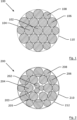
- Figure 1 shows a cross section of a Warrington strand 100 as it is known. It comprises a core 102 that is surrounded by 6 first steel filaments 104 circumferentially arranged around the core in an intermediate layer.
- the core is in this case a single steel filament having a core diameter.
- the 6 first steel filaments 104 all have a first diameter.
- the outer layer comprises 12 filaments circumferentially arranged around the intermediate layer. All filaments are twisted around the core with the same final lay length and twist direction. 6 of the outer layer steel filaments - marked 106 - have a second diameter while the remaining six outer layer filaments 108 have a third diameter.
- the second and third diameters are chosen such that all filaments of the outer layer are tangent to a single circumscribing circle 110.
- the overall diameter of the strand is 3 mm.
- the core diameter is 663 ⁇ m
- the first diameter is 651 ⁇ m
- the second diameter is 519 ⁇ m
- the third diameter is 681 ⁇ m.
- the lay length of the filaments is 24 mm i.e. 8 times the diameter of the strand.
- the ratio of largest to smallest diameter is 1.312 and fill factor is 81.8%. No gaps are present between the filaments of the intermediate layer.
- This kind of strand is popular as an outer strand of known elevator ropes.
- Figure 2 shows another example 200 not according the invention according claim 1 ('dW21'). It has a core 203 that comprises three filaments 202 of size 120 ⁇ m diameter twisted together at a lay of 3.8 mm in Z direction. The core 203 has thus a diameter 'd 0 ' of 259 ⁇ m.
- the intermediate layer steel filaments 204 have a first diameter of 210 ⁇ m. The number N has been set to 6.
- the intermediate layer is surrounded by an outer layer consisting of 12 steel filaments: 6 second steel filaments 206 and 6 third steel filaments 208.
- the second diameter is 223 ⁇ m.
- the third diameter is 170 ⁇ m.
- the first radius 205 is 130 ⁇ m.
- the second radius 212 is 500 ⁇ m
- the third radius 210 is 510 ⁇ m.
- the first, second and third radius can be calculated by simple trigonometry from the measured filament sizes and/or from a cross section.
- the gap between the filaments of the outer layer at final lay length is 11 ⁇ m.
- the diameter of the strand is thus 1.02 mm.
- the closing lay length CL is 2.56 mm. At this lay length the gap between the intermediate filaments is closed.
- the final lay length with which core, intermediate layer filaments and outer layer filaments are twisted together in the final product is 10 mm. Hence the final lay length is between 2 ⁇ CL i.e. 5.12 mm and 6 ⁇ CL i.e. 15.36 mm.
- This reinforcement strand turned out to be a large improvement to the multi strand cord 7 ⁇ 3 ⁇ 0.15 that is well known to reinforce synchronous belts.
- the latter is composed of 7 strands twisted together at a lay of 8 mm in S (alternatively Z) direction of which each strand consists of three filaments twisted together a 9 mm in Z direction (alternatively S). Note that both dW21 and 7 ⁇ 3 ⁇ 0.15 have the same number of filaments.
- Table 1 shows a comparison of the main parameters of both: Table 1 Parameter dW21 7 ⁇ 3 ⁇ 0.15 Diameter (mm) 1.02 0.91 Actual breaking load (N) 1 750 950 950 950 950 950 950 950 950 950 950 950 950 950 950 950 950 950 950 950 950 950 950 950 950 950 950 950 950 950 950 950 950 950 950 950 950 950 950 950 950 950 950 950 950 950 950 950 950 950 950 950 950 950 950 950 950 950 950 950 950 950 950 950 950 950 950 950 950 950 950 950 950 950 950 950 950 950 950 950 950 950 950 950 950 950 950 950 950 950 950 950 950 950 950 950 950 950 950 950 950 950 950 950 950
- 'MBL' is meant the 'Minimum Breaking Load'. This is the lowest breaking load that can be expected based on 6-sigma statistical variation. For the purpose of this application it is set to 7% lower than the actual breaking load.
- the 'modulus in the linear region' is taken in a region of the load elongation curve that is linear e.g. in a region above 10% of the MBL.
- the inventors attribute this to two major features:
- Figure 4 shows an implementation 'dW24' of the reinforcement strand 400 with N equal to 7 according the invention. It is described by the following formula (brackets denote different twisting steps, numbers represent diameters of filaments in millimetre, subindices indicate final lay length in mm and direction): 3 ⁇ 0.18 5.6 s + 7 ⁇ 0.26 + 7 ⁇ 0.285
- the core 403 is a 3 ⁇ 1 strand of three 0.18 filaments 402 twisted together at lay 5.6 mm in ⁇ s' direction.
- the mirror image is equally well possible (all lay directions reversed).
- the 7x7/1.6 has a larger diameter, the axial stiffness in the working region (2 to 10% of MBL) is lower than for the inventive reinforcement strand.
- the cord is in test and does not show core migration.
- Table 4 describe another embodiment according the invention that is of the following make: 0.24 + 6 ⁇ 0.23 7.2 z + 9 ⁇ 0.33 + 9 ⁇ 0.30
- Table 5 Parameter dW34 7 ⁇ 7/1.8 Diameter (mm) 1.80 1.80 Actual breaking load (N) 5 900 3 965 Metallic cross section (mm 2 ) 2.01 1.54 Fill factor (%) 79 61 Axial stiffness between 2 to 10% of MBL (N/%) 2 734 1 570
- the (1+6) core is replaced with an equal lay construction of the following type: 3 ⁇ 0.18 + 3 ⁇ 0.15 0.22 0.15 7.2 z + 9 ⁇ 0.33 + 9 ⁇ 0.30
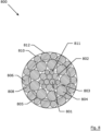
- FIG. 8 A cross section of the reinforcement strand with such a core is depicted in Figure 8 .
- the filaments of the outer layer are as in that of Figure 5 . Only the core is different.
- the core-core is formed by three filaments 801 of diameter 0.18.
- 015 indicates that the outer layer of the core is formed of three groups of each time three filaments: one middle filament of larger size (0.22 mm, indicated 802) that has two neighbouring filaments of smaller diameter (0.15 mm, indicated ). This results in a fairly round core of diameter 0.70 mm.
- the wires are hot dip galvanized with a coating weight of 5 gram per kilogram of strand.
- Figure 6 shows such a belt 600 that is reinforced with the reinforcement strands 604 according the invention. It is a flat belt that is suitable as an elevator belt. It has a width 'W' of 38.5 mm and a thickness 't' 4.5 mm.
- the 10 reinforcement strands 604 extend parallel to one another over the length of the belt 600.
- the lens 606 shows the reinforcement according the dW21 embodiment.
- the pitch 'p' between the strands - center to center - is 3.25 mm i.e. about 2.5 times the diameter of the reinforcement strand. They are held in position by means of a polymer jacket of polyurethane 602.
- the belt has a breaking load of 30 kN.
- the reinforcement strand dW21 does have some surface roughness due to the different second and third radii this surface roughness is much less than that of for example a 7 ⁇ 7 type of cord. While for a 7 ⁇ 7 cord the use of an adhesive is not absolutely necessary, it does turn out to be beneficial to use an organic primer to promote the adhesion between the reinforcement strand according the invention and the polymer jacket. For the described case an organo functional silane was used. It took 650 N to pull out a length of 12.5 mm of reinforcement strand out of the belt. The adhesion force per unit length is thus 52 N/mm that is larger than 30 times the diameter of the reinforcement strand i.e. 39 N per mm of embedded strand.
- a synchronous belt is build up in much the same way as the belt 600 except that one side of the belt is provided with teeth for engagement with toothed pulley.
- the other considerations as for the elevator belt are also valid for this kind of belt.
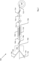
- Figure 7 shows the method 700 in its most general form.
- a twisting device 702 twists the N first steel filaments of the intermediate layer 724 and the N second 726 and N third steel filaments 728 around the core 722 with a certain final lay length indicated with the hatching 706 (Z direction).
- the strand 704 is the result of this operation.
- the twisting device 702 can be a cabling machine or a bunching machine that are devices known as such in the art.
- This strand 704 is then guided through a first torsion restriction pulley set 708, a false twister 712 and second torsion restriction pulley set 716.
- Torsion restriction pulleys and false twisters are known as such in the art.
- the lay length of the reinforcement strand is shortened to the intermediate lay length as indicated by the hatching 710.
- the intermediate reinforcement strand 705 is formed.
- the intermediate lay length is again lengthened to the final lay length 714 (equal to 706) after torsion restriction pulleys 716.
- the reinforcement strand 715 is wound on bobbin 718.
- the cross section at 704 looks as depicted in Figure 2 .
- the lay length will be shortened when the false twister turns in clockwise direction when viewed from the torsion restriction pulleys 708 side.
- the cross section of Figure 2 will thus evolve into the cross section of Figure 3.
- Figure 3 shows the cross section of the first embodiment but at a shorter lay length than the final lay length in this case right at the closing lay length.
- the intermediate layer filaments 304 is wrung around core 303 without a radial movement of the intermediate layer filaments up to the point that no gap forms in between the intermediate layer filaments.
- the effect can be further improved by radially compressing the outer layer steel filaments towards the intermediate layer.
- This can for example be done by the introduction of a compression means 720 that can be in the form of pulleys such as torsion restriction pulleys, a straightener or even a cabling die of correct diameter.
- the twisting device 702 can be a simple pay off unit that pays off product that shows core migration.
- the cord can be corrected to show no core migration.
- the structural features of the reinforcement strand have to be according to the claims as otherwise the method will not work.
- the use of the method is well recognizable as the intermediate layer will retract into the cut end relative to the outer layer of filaments. This is the preferred stress state of the intermediate layer filaments.
Landscapes
- Engineering & Computer Science (AREA)
- General Engineering & Computer Science (AREA)
- Mechanical Engineering (AREA)
- Ropes Or Cables (AREA)
Claims (13)
- Toron de renforcement (400, 500, 800) destiné à renforcer un article polymère, ledit toron de renforcement comprenant une âme (403, 503, 803) ayant un diamètre d'âme et des filaments d'acier (404, 406, 408 ; 501, 502, 504, 506, 508 ; 801, 811, 804, 806, 808),lesdits filaments d'acier étant organisés en- une couche intermédiaire comprenant N premiers filaments d'acier (404, 504, 804) disposés circonférentiellement autour de ladite âme, où N est égal à 5, 6, 7, 8 ou 9, lesdits premiers filaments d'acier ayant un premier diamètre, ledit diamètre d'âme et ledit premier diamètre étant tels qu'un espace se forme entre lesdits premiers filaments d'acier et- une couche externe comprenant 2N filaments d'acier (406, 408 ; 506, 508 ; 806, 808) disposés circonférentiellement autour de ladite couche intermédiaire,lesdits filaments d'acier de ladite couche intermédiaire et de ladite couche externe étant tordus autour de ladite âme avec le même pas de câblage final et la même direction, caractérisé en ce queledit pas de câblage final est supérieur à deux fois et inférieur à six fois le pas de câblage de fermeture, ledit pas de câblage de fermeture étant le pas de câblage auquel l'espace entre lesdits premiers filaments (404, 504, 804) de la couche intermédiaire est fermé et dans lequel il n'y a pas d'espace entre les filaments de la couche externe (406, 408 ; 506, 508 ; 806, 808) au pas de câblage final.
- Toron de renforcement (400, 500, 800) selon la revendication 1 dans lequel ladite couche externe comprend- N deuxièmes filaments d'acier d'un deuxième diamètre (406 ; 506 ; 806), lesdits N deuxièmes filaments d'acier étant tangents à un deuxième cercle circonscrivant (412 ; 512 ; 812) ayant un deuxième rayon ; et- N troisièmes filaments d'acier d'un troisième diamètre (408 ; 508 ; 808), lesdits N troisièmes filaments d'acier étant tangents à un troisième cercle circonscrivant (412 ; 512 ; 812) ayant un troisième rayon ;ledit deuxième diamètre étant plus grand que ledit troisième diamètre, lesdits deuxièmes filaments d'acier et lesdits troisièmes filaments d'acier occupant des positions alternées dans ladite couche externe, dans lequel le deuxième rayon est plus grand que le troisième rayon.
- Toron de renforcement selon la revendication 1 ou 2 dans lequel ladite âme est un seul filament d'acier comprenant des courbes avec des segments rectilignes entre elles.
- Toron de renforcement (400, 800) selon la revendication 1 ou 2 dans lequel ladite âme (403, 803) est un toron à fils parallèles dans lequel tous les filaments d'acier d'âme (402 ; 801, 802, 811) sont dépourvus de déformations hélicoïdales d'ordre zéro et sont tordus ensemble avec un pas de câblage d'âme différent du pas de câblage final dudit toron de renforcement.
- Toron de renforcement (400) selon la revendication 4 dans lequel le nombre de filaments d'acier d'âme (403) s'élève à deux ou trois ou quatre et lesdits filaments d'acier d'âme ont un diamètre égal.
- Toron de renforcement (800) selon la revendication 4 dans lequel le nombre de filaments d'acier d'âme s'élève à neuf ou douze (803) et dans lequel les filaments d'acier d'âme (801, 802, 811) sont disposés dans une construction de type semi-Warrington.
- Toron de renforcement (500) selon la revendication 1 ou 2 dans lequel ladite âme (503) est un toron comprenant une âme d'âme (501) et 5, 6 ou 7 filaments d'acier externes d'âme (502) tordus autour de ladite âme d'âme avec un pas de câblage d'âme différent du pas de câblage final dudit toron de renforcement.
- Toron de renforcement (400, 500, 800) selon l'une quelconque des revendications 1 à 7, lesdits filaments d'acier dudit toron de renforcement étant pourvus d'un revêtement métallique ou d'un revêtement d'alliage métallique.
- Toron de renforcement (400, 500, 800) selon l'une quelconque des revendications 1 à 8, ledit toron de renforcement étant pourvu d'un apprêt organique qui favorise l'adhérence à un polymère.
- Toron de renforcement (400, 500, 800) selon la revendication 9 dans lequel ledit apprêt organique en est un du groupe comprenant les silanes organofonctionnels, les zirconates organofonctionnels et les titanates organofonctionnels.
- Procédé de fabrication d'un toron de renforcement (700) comprenant les étapes suivantes :- obtention d'une âme (722) ayant un diamètre d'âme ;- obtention de N premiers filaments d'acier ayant un premier diamètre (724) ;- obtention de N deuxièmes filaments d'acier ayant un deuxième diamètre (726), plus grand que ledit premier diamètre ;- obtention de N troisièmes filaments d'acier ayant un troisième diamètre (728) ;- torsion de ladite âme (722), desdits N premiers filaments d'acier (724), desdits N deuxièmes filaments d'acier (726) et desdits N troisièmes filaments d'acier (728) ensemble dans une direction de câblage jusqu'à un pas de câblage final (706), lesdits N premiers filaments d'acier (724) formant une couche intermédiaire, lesdits N deuxièmes (726) et N troisièmes (728) filaments d'acier formant une couche externe, lesdits N deuxièmes et N troisièmes filaments d'acier occupant des positions alternées dans ladite couche externe ;caractérisé en ce que,
pendant ladite torsion, le pas de câblage intermédiaire (710) des premiers, deuxièmes et troisièmes filaments d'acier est raccourci pour se retrouver entre le pas de câblage de fermeture et 83 % du pas de câblage final, et ensuite, les premiers, deuxièmes et troisièmes filaments d'acier sont détordus jusqu'audit pas de câblage final (706), moyennant quoi ledit pas de câblage intermédiaire reste supérieur ou égal au pas de câblage de fermeture, ledit pas de câblage de fermeture étant le pas de câblage auquel les premiers filaments d'acier dans ladite couche intermédiaire se touchent. - Procédé de la revendication 11 dans lequel, au pas de câblage intermédiaire (710), les deuxièmes (726) et troisièmes (728) filaments d'acier de la couche externe sont comprimés radialement vers ladite couche intermédiaire.
- Toron de renforcement produit selon le procédé de la revendication 11 ou 12 (200, 400, 500, 800), caractérisé en ce que, lors de la découpe du toron de renforcement pour former ainsi une extrémité de toron de renforcement, au moins lesdits premiers filaments d'acier de ladite couche intermédiaire (206, 406, 506, 806) se rétractent à l'intérieur de l'extrémité de toron de renforcement.
Applications Claiming Priority (2)
| Application Number | Priority Date | Filing Date | Title |
|---|---|---|---|
| EP17177992 | 2017-06-27 | ||
| PCT/EP2018/066861 WO2019002162A1 (fr) | 2017-06-27 | 2018-06-25 | Brin de renfort pour renforcer un article polymère |
Publications (2)
| Publication Number | Publication Date |
|---|---|
| EP3645785A1 EP3645785A1 (fr) | 2020-05-06 |
| EP3645785B1 true EP3645785B1 (fr) | 2024-06-19 |
Family
ID=59227592
Family Applications (1)
| Application Number | Title | Priority Date | Filing Date |
|---|---|---|---|
| EP18733271.3A Active EP3645785B1 (fr) | 2017-06-27 | 2018-06-25 | Toron de renforcement destinée à renforcer un article polymère |
Country Status (10)
| Country | Link |
|---|---|
| US (2) | US11186947B2 (fr) |
| EP (1) | EP3645785B1 (fr) |
| JP (1) | JP7508228B2 (fr) |
| KR (1) | KR102653649B1 (fr) |
| CN (2) | CN110799701B (fr) |
| ES (1) | ES2986576T3 (fr) |
| FI (1) | FI3645785T3 (fr) |
| HU (1) | HUE067914T2 (fr) |
| PL (1) | PL3645785T3 (fr) |
| WO (1) | WO2019002162A1 (fr) |
Families Citing this family (10)
| Publication number | Priority date | Publication date | Assignee | Title |
|---|---|---|---|---|
| WO2019081412A1 (fr) * | 2017-10-27 | 2019-05-02 | Bekaert Advanced Cords Aalter Nv | Courroie comprenant des câbles d'acier conçus pour la détection de l'usure |
| CN107953728B (zh) * | 2017-11-27 | 2020-02-11 | 江苏兴达钢帘线股份有限公司 | 一种缆型胎圈及轮胎 |
| WO2021204727A1 (fr) * | 2020-04-08 | 2021-10-14 | Bridon International Limited | Câble métallique et ensemble comprenant un tel câble métallique |
| CN111648148A (zh) * | 2020-05-11 | 2020-09-11 | 贵州钢绳股份有限公司 | 一种Φ50mm高级建筑物用不锈钢单股钢丝绳 |
| CN114687228A (zh) * | 2022-03-22 | 2022-07-01 | 南通久泰新材料科技有限公司 | 一种合成纤维复合缆绳及其加工方法 |
| CN115323816B (zh) * | 2022-08-31 | 2023-05-16 | 江苏兴达钢帘线股份有限公司 | 一种钢丝变形装置、其使用方法及帘线生产装置 |
| US12612287B1 (en) * | 2023-03-16 | 2026-04-28 | Otis Elevator Company | High strength cord with improved detectability |
| CN116397452A (zh) * | 2023-05-24 | 2023-07-07 | 江苏兴达钢帘线股份有限公司 | 一种钢丝帘线 |
| WO2025168369A1 (fr) | 2024-02-09 | 2025-08-14 | Bekaert Advanced Cords Aalter Nv | Brin d'acier et courroie renforcée par ledit brin d'acier |
| US20260109576A1 (en) * | 2024-10-23 | 2026-04-23 | Otis Elevator Company | Elevator belt with steel cord |
Family Cites Families (25)
| Publication number | Priority date | Publication date | Assignee | Title |
|---|---|---|---|---|
| BE655593A (fr) | 1964-11-12 | 1965-03-01 | ||
| GB1582647A (en) * | 1977-07-07 | 1981-01-14 | Bekaert Sa Nv | Metal cord |
| US4829760A (en) | 1987-05-04 | 1989-05-16 | N.B. Bekaert S.A. | Compact steel cord structure |
| BE1004469A3 (nl) | 1991-02-06 | 1992-11-24 | Bekaert Sa Nv | Versterkte transmissieriem. |
| JPH05186975A (ja) * | 1992-01-10 | 1993-07-27 | Kokoku Kousensaku Kk | タイヤ用スチールコード |
| US6401871B2 (en) | 1998-02-26 | 2002-06-11 | Otis Elevator Company | Tension member for an elevator |
| DE29924774U1 (de) | 1998-12-22 | 2005-07-07 | Otis Elevator Co., Farmington | Aufzugsystem |
| FR2795751A1 (fr) | 1999-06-29 | 2001-01-05 | Michelin Soc Tech | Cable d'acier multicouches pour carcasse de pneumatique |
| WO2001086058A1 (fr) | 2000-05-08 | 2001-11-15 | N.V. Bekaert S.A. | Cable d'acier revetu de zinc a resistance a la fatigue amelioree |
| DE10213289A1 (de) * | 2001-03-30 | 2002-11-14 | Yokohama Rubber Co Ltd | Elastomer-und-Stahlkord-Verbundwerkstoff und Prozess zur Herstellung desselben |
| EP1555233B1 (fr) | 2002-10-25 | 2018-06-06 | Mitsubishi Denki Kabushiki Kaisha | Cordage pour ascenseur |
| DE602004019396D1 (de) | 2003-02-27 | 2009-03-26 | Bekaert Sa Nv | Aufzugsseil |
| JP4053910B2 (ja) | 2003-03-18 | 2008-02-27 | 東洋ゴム工業株式会社 | スチールコード及び空気入りラジアルタイヤ |
| KR101184642B1 (ko) | 2003-11-03 | 2012-09-20 | 엔브이 베카에르트 에스에이 | 낮은 구조적 신장도를 가지는 파인 스틸 코드 |
| WO2007020156A1 (fr) * | 2005-08-19 | 2007-02-22 | Nv Bekaert Sa | Cable en acier impregne de polymere |
| EP2097581B1 (fr) | 2006-12-29 | 2016-08-24 | Bekaert Advanced Cords Aalter NV | Câble d'acier à commettage parallèle pour le renforcement des élastomères |
| CN201010815Y (zh) * | 2007-02-10 | 2008-01-23 | 贵州钢绳(集团)有限责任公司 | 多丝线接触结构预应力混凝土用钢绞线 |
| BRPI0922654A2 (pt) | 2008-12-16 | 2020-08-11 | Nv Bekaert Sa | fio tendo um revestimento de promoção de adesão aperfeiçoada |
| FR2943691B1 (fr) * | 2009-03-31 | 2011-08-19 | Michelin Soc Tech | Procede et dispositif de fabrication d'un cable a trois couches du type gomme in situ |
| FR2946366B1 (fr) * | 2009-06-03 | 2011-12-02 | Michelin Soc Tech | Cable a trois couches,gomme in situ,pour armature carcasse de pneumatique. |
| CN203498695U (zh) * | 2010-10-27 | 2014-03-26 | 贝卡尔特公司 | 开放式钢帘线 |
| EA024603B9 (ru) * | 2011-01-10 | 2018-04-30 | Нв Бекаэрт Са | Компактный стальной корд |
| RU2553967C2 (ru) | 2011-04-14 | 2015-06-20 | Отис Элевэйтор Компани | Канат или ремень с покрытием для подъемных систем |
| WO2014063900A1 (fr) * | 2012-10-22 | 2014-05-01 | Nv Bekaert Sa | Courroie de levage |
| CN205839457U (zh) * | 2016-07-11 | 2016-12-28 | 鞍钢钢绳有限责任公司 | 一种铸造级吊车用八股钢丝绳结构 |
-
2018
- 2018-06-25 ES ES18733271T patent/ES2986576T3/es active Active
- 2018-06-25 CN CN201880043444.XA patent/CN110799701B/zh active Active
- 2018-06-25 KR KR1020207001956A patent/KR102653649B1/ko active Active
- 2018-06-25 US US16/624,493 patent/US11186947B2/en not_active Expired - Fee Related
- 2018-06-25 PL PL18733271.3T patent/PL3645785T3/pl unknown
- 2018-06-25 FI FIEP18733271.3T patent/FI3645785T3/fi active
- 2018-06-25 JP JP2019572743A patent/JP7508228B2/ja active Active
- 2018-06-25 CN CN202211427164.3A patent/CN115652669A/zh active Pending
- 2018-06-25 WO PCT/EP2018/066861 patent/WO2019002162A1/fr not_active Ceased
- 2018-06-25 EP EP18733271.3A patent/EP3645785B1/fr active Active
- 2018-06-25 HU HUE18733271A patent/HUE067914T2/hu unknown
-
2021
- 2021-10-28 US US17/513,038 patent/US11708665B2/en active Active
Also Published As
| Publication number | Publication date |
|---|---|
| US20220049418A1 (en) | 2022-02-17 |
| US20200115851A1 (en) | 2020-04-16 |
| US11186947B2 (en) | 2021-11-30 |
| PL3645785T3 (pl) | 2024-11-04 |
| KR20200023399A (ko) | 2020-03-04 |
| CN110799701A (zh) | 2020-02-14 |
| WO2019002162A1 (fr) | 2019-01-03 |
| FI3645785T3 (fi) | 2024-09-18 |
| ES2986576T3 (es) | 2024-11-12 |
| EP3645785A1 (fr) | 2020-05-06 |
| HUE067914T2 (hu) | 2024-11-28 |
| CN115652669A (zh) | 2023-01-31 |
| KR102653649B1 (ko) | 2024-04-03 |
| US11708665B2 (en) | 2023-07-25 |
| JP2020525666A (ja) | 2020-08-27 |
| JP7508228B2 (ja) | 2024-07-01 |
| CN110799701B (zh) | 2022-11-11 |
Similar Documents
| Publication | Publication Date | Title |
|---|---|---|
| US11708665B2 (en) | Reinforcement strand for reinforcing a polymer article | |
| EP3645442B1 (fr) | Courroie renforcée par des fils d'acier | |
| KR101491907B1 (ko) | 하이브리드 코어 로프 | |
| KR100367116B1 (ko) | 개방구조의스틸코드및그것의제조방법 | |
| JP5378231B2 (ja) | エラストマー補強用の単撚り鋼コード | |
| JP5623425B2 (ja) | タイヤ補強用鋼コード | |
| EP2550392A1 (fr) | Câblé métallique avec fils préformés pour pneu pour service hors-route | |
| KR102712572B1 (ko) | 엘라스토머 보강용 스틸 코드 | |
| EP1381730B1 (fr) | Cable d'acier pour le renforcement d'articles en caoutchouc | |
| RU2740988C1 (ru) | Канат стальной восьмипрядный | |
| CN223907235U (zh) | 钢丝股和利用钢丝股增强的带 | |
| RU2167968C2 (ru) | Витая проволочная структура |
Legal Events
| Date | Code | Title | Description |
|---|---|---|---|
| STAA | Information on the status of an ep patent application or granted ep patent |
Free format text: STATUS: UNKNOWN |
|
| STAA | Information on the status of an ep patent application or granted ep patent |
Free format text: STATUS: THE INTERNATIONAL PUBLICATION HAS BEEN MADE |
|
| PUAI | Public reference made under article 153(3) epc to a published international application that has entered the european phase |
Free format text: ORIGINAL CODE: 0009012 |
|
| STAA | Information on the status of an ep patent application or granted ep patent |
Free format text: STATUS: REQUEST FOR EXAMINATION WAS MADE |
|
| 17P | Request for examination filed |
Effective date: 20191127 |
|
| AK | Designated contracting states |
Kind code of ref document: A1 Designated state(s): AL AT BE BG CH CY CZ DE DK EE ES FI FR GB GR HR HU IE IS IT LI LT LU LV MC MK MT NL NO PL PT RO RS SE SI SK SM TR |
|
| AX | Request for extension of the european patent |
Extension state: BA ME |
|
| DAV | Request for validation of the european patent (deleted) | ||
| DAX | Request for extension of the european patent (deleted) | ||
| STAA | Information on the status of an ep patent application or granted ep patent |
Free format text: STATUS: EXAMINATION IS IN PROGRESS |
|
| 17Q | First examination report despatched |
Effective date: 20210915 |
|
| P01 | Opt-out of the competence of the unified patent court (upc) registered |
Effective date: 20230619 |
|
| GRAP | Despatch of communication of intention to grant a patent |
Free format text: ORIGINAL CODE: EPIDOSNIGR1 |
|
| STAA | Information on the status of an ep patent application or granted ep patent |
Free format text: STATUS: GRANT OF PATENT IS INTENDED |
|
| INTG | Intention to grant announced |
Effective date: 20231222 |
|
| GRAJ | Information related to disapproval of communication of intention to grant by the applicant or resumption of examination proceedings by the epo deleted |
Free format text: ORIGINAL CODE: EPIDOSDIGR1 |
|
| STAA | Information on the status of an ep patent application or granted ep patent |
Free format text: STATUS: EXAMINATION IS IN PROGRESS |
|
| GRAS | Grant fee paid |
Free format text: ORIGINAL CODE: EPIDOSNIGR3 |
|
| STAA | Information on the status of an ep patent application or granted ep patent |
Free format text: STATUS: GRANT OF PATENT IS INTENDED |
|
| GRAP | Despatch of communication of intention to grant a patent |
Free format text: ORIGINAL CODE: EPIDOSNIGR1 |
|
| GRAA | (expected) grant |
Free format text: ORIGINAL CODE: 0009210 |
|
| STAA | Information on the status of an ep patent application or granted ep patent |
Free format text: STATUS: THE PATENT HAS BEEN GRANTED |
|
| INTC | Intention to grant announced (deleted) | ||
| INTG | Intention to grant announced |
Effective date: 20240506 |
|
| AK | Designated contracting states |
Kind code of ref document: B1 Designated state(s): AL AT BE BG CH CY CZ DE DK EE ES FI FR GB GR HR HU IE IS IT LI LT LU LV MC MK MT NL NO PL PT RO RS SE SI SK SM TR |
|
| REG | Reference to a national code |
Ref country code: GB Ref legal event code: FG4D |
|
| REG | Reference to a national code |
Ref country code: CH Ref legal event code: EP |
|
| REG | Reference to a national code |
Ref country code: DE Ref legal event code: R096 Ref document number: 602018070763 Country of ref document: DE |
|
| REG | Reference to a national code |
Ref country code: NL Ref legal event code: FP |
|
| REG | Reference to a national code |
Ref country code: FI Ref legal event code: FGE |
|
| PGFP | Annual fee paid to national office [announced via postgrant information from national office to epo] |
Ref country code: NL Payment date: 20240813 Year of fee payment: 7 |
|
| PG25 | Lapsed in a contracting state [announced via postgrant information from national office to epo] |
Ref country code: BG Free format text: LAPSE BECAUSE OF FAILURE TO SUBMIT A TRANSLATION OF THE DESCRIPTION OR TO PAY THE FEE WITHIN THE PRESCRIBED TIME-LIMIT Effective date: 20240619 |
|
| REG | Reference to a national code |
Ref country code: SK Ref legal event code: T3 Ref document number: E 44760 Country of ref document: SK |
|
| PG25 | Lapsed in a contracting state [announced via postgrant information from national office to epo] |
Ref country code: HR Free format text: LAPSE BECAUSE OF FAILURE TO SUBMIT A TRANSLATION OF THE DESCRIPTION OR TO PAY THE FEE WITHIN THE PRESCRIBED TIME-LIMIT Effective date: 20240619 |
|
| PGFP | Annual fee paid to national office [announced via postgrant information from national office to epo] |
Ref country code: IE Payment date: 20240730 Year of fee payment: 7 |
|
| REG | Reference to a national code |
Ref country code: LT Ref legal event code: MG9D |
|
| PG25 | Lapsed in a contracting state [announced via postgrant information from national office to epo] |
Ref country code: GR Free format text: LAPSE BECAUSE OF FAILURE TO SUBMIT A TRANSLATION OF THE DESCRIPTION OR TO PAY THE FEE WITHIN THE PRESCRIBED TIME-LIMIT Effective date: 20240920 |
|
| PGFP | Annual fee paid to national office [announced via postgrant information from national office to epo] |
Ref country code: AT Payment date: 20240731 Year of fee payment: 7 |
|
| PGFP | Annual fee paid to national office [announced via postgrant information from national office to epo] |
Ref country code: HU Payment date: 20240822 Year of fee payment: 7 Ref country code: SK Payment date: 20240819 Year of fee payment: 7 |
|
| PG25 | Lapsed in a contracting state [announced via postgrant information from national office to epo] |
Ref country code: LV Free format text: LAPSE BECAUSE OF FAILURE TO SUBMIT A TRANSLATION OF THE DESCRIPTION OR TO PAY THE FEE WITHIN THE PRESCRIBED TIME-LIMIT Effective date: 20240619 |
|
| PG25 | Lapsed in a contracting state [announced via postgrant information from national office to epo] |
Ref country code: NO Free format text: LAPSE BECAUSE OF FAILURE TO SUBMIT A TRANSLATION OF THE DESCRIPTION OR TO PAY THE FEE WITHIN THE PRESCRIBED TIME-LIMIT Effective date: 20240919 Ref country code: LV Free format text: LAPSE BECAUSE OF FAILURE TO SUBMIT A TRANSLATION OF THE DESCRIPTION OR TO PAY THE FEE WITHIN THE PRESCRIBED TIME-LIMIT Effective date: 20240619 Ref country code: HR Free format text: LAPSE BECAUSE OF FAILURE TO SUBMIT A TRANSLATION OF THE DESCRIPTION OR TO PAY THE FEE WITHIN THE PRESCRIBED TIME-LIMIT Effective date: 20240619 Ref country code: GR Free format text: LAPSE BECAUSE OF FAILURE TO SUBMIT A TRANSLATION OF THE DESCRIPTION OR TO PAY THE FEE WITHIN THE PRESCRIBED TIME-LIMIT Effective date: 20240920 Ref country code: BG Free format text: LAPSE BECAUSE OF FAILURE TO SUBMIT A TRANSLATION OF THE DESCRIPTION OR TO PAY THE FEE WITHIN THE PRESCRIBED TIME-LIMIT Effective date: 20240619 Ref country code: RS Free format text: LAPSE BECAUSE OF FAILURE TO SUBMIT A TRANSLATION OF THE DESCRIPTION OR TO PAY THE FEE WITHIN THE PRESCRIBED TIME-LIMIT Effective date: 20240919 |
|
| PGFP | Annual fee paid to national office [announced via postgrant information from national office to epo] |
Ref country code: RO Payment date: 20240912 Year of fee payment: 7 |
|
| REG | Reference to a national code |
Ref country code: ES Ref legal event code: FG2A Ref document number: 2986576 Country of ref document: ES Kind code of ref document: T3 Effective date: 20241112 |
|
| REG | Reference to a national code |
Ref country code: HU Ref legal event code: AG4A Ref document number: E067914 Country of ref document: HU |
|
| PGFP | Annual fee paid to national office [announced via postgrant information from national office to epo] |
Ref country code: TR Payment date: 20240910 Year of fee payment: 7 |
|
| PG25 | Lapsed in a contracting state [announced via postgrant information from national office to epo] |
Ref country code: PT Free format text: LAPSE BECAUSE OF FAILURE TO SUBMIT A TRANSLATION OF THE DESCRIPTION OR TO PAY THE FEE WITHIN THE PRESCRIBED TIME-LIMIT Effective date: 20241021 |
|
| PG25 | Lapsed in a contracting state [announced via postgrant information from national office to epo] |
Ref country code: PT Free format text: LAPSE BECAUSE OF FAILURE TO SUBMIT A TRANSLATION OF THE DESCRIPTION OR TO PAY THE FEE WITHIN THE PRESCRIBED TIME-LIMIT Effective date: 20241021 |
|
| PGFP | Annual fee paid to national office [announced via postgrant information from national office to epo] |
Ref country code: PL Payment date: 20240808 Year of fee payment: 7 |
|
| PG25 | Lapsed in a contracting state [announced via postgrant information from national office to epo] |
Ref country code: EE Free format text: LAPSE BECAUSE OF FAILURE TO SUBMIT A TRANSLATION OF THE DESCRIPTION OR TO PAY THE FEE WITHIN THE PRESCRIBED TIME-LIMIT Effective date: 20240619 |
|
| PG25 | Lapsed in a contracting state [announced via postgrant information from national office to epo] |
Ref country code: IS Free format text: LAPSE BECAUSE OF FAILURE TO SUBMIT A TRANSLATION OF THE DESCRIPTION OR TO PAY THE FEE WITHIN THE PRESCRIBED TIME-LIMIT Effective date: 20241019 |
|
| PG25 | Lapsed in a contracting state [announced via postgrant information from national office to epo] |
Ref country code: CZ Free format text: LAPSE BECAUSE OF FAILURE TO SUBMIT A TRANSLATION OF THE DESCRIPTION OR TO PAY THE FEE WITHIN THE PRESCRIBED TIME-LIMIT Effective date: 20240619 |
|
| PG25 | Lapsed in a contracting state [announced via postgrant information from national office to epo] |
Ref country code: SM Free format text: LAPSE BECAUSE OF FAILURE TO SUBMIT A TRANSLATION OF THE DESCRIPTION OR TO PAY THE FEE WITHIN THE PRESCRIBED TIME-LIMIT Effective date: 20240619 |
|
| PG25 | Lapsed in a contracting state [announced via postgrant information from national office to epo] |
Ref country code: SM Free format text: LAPSE BECAUSE OF FAILURE TO SUBMIT A TRANSLATION OF THE DESCRIPTION OR TO PAY THE FEE WITHIN THE PRESCRIBED TIME-LIMIT Effective date: 20240619 Ref country code: IS Free format text: LAPSE BECAUSE OF FAILURE TO SUBMIT A TRANSLATION OF THE DESCRIPTION OR TO PAY THE FEE WITHIN THE PRESCRIBED TIME-LIMIT Effective date: 20241019 Ref country code: EE Free format text: LAPSE BECAUSE OF FAILURE TO SUBMIT A TRANSLATION OF THE DESCRIPTION OR TO PAY THE FEE WITHIN THE PRESCRIBED TIME-LIMIT Effective date: 20240619 Ref country code: CZ Free format text: LAPSE BECAUSE OF FAILURE TO SUBMIT A TRANSLATION OF THE DESCRIPTION OR TO PAY THE FEE WITHIN THE PRESCRIBED TIME-LIMIT Effective date: 20240619 |
|
| REG | Reference to a national code |
Ref country code: CH Ref legal event code: PL |
|
| PG25 | Lapsed in a contracting state [announced via postgrant information from national office to epo] |
Ref country code: LU Free format text: LAPSE BECAUSE OF NON-PAYMENT OF DUE FEES Effective date: 20240625 |
|
| PG25 | Lapsed in a contracting state [announced via postgrant information from national office to epo] |
Ref country code: MC Free format text: LAPSE BECAUSE OF FAILURE TO SUBMIT A TRANSLATION OF THE DESCRIPTION OR TO PAY THE FEE WITHIN THE PRESCRIBED TIME-LIMIT Effective date: 20240619 |
|
| REG | Reference to a national code |
Ref country code: DE Ref legal event code: R097 Ref document number: 602018070763 Country of ref document: DE |
|
| PG25 | Lapsed in a contracting state [announced via postgrant information from national office to epo] |
Ref country code: MC Free format text: LAPSE BECAUSE OF FAILURE TO SUBMIT A TRANSLATION OF THE DESCRIPTION OR TO PAY THE FEE WITHIN THE PRESCRIBED TIME-LIMIT Effective date: 20240619 |
|
| PG25 | Lapsed in a contracting state [announced via postgrant information from national office to epo] |
Ref country code: DK Free format text: LAPSE BECAUSE OF FAILURE TO SUBMIT A TRANSLATION OF THE DESCRIPTION OR TO PAY THE FEE WITHIN THE PRESCRIBED TIME-LIMIT Effective date: 20240619 |
|
| PG25 | Lapsed in a contracting state [announced via postgrant information from national office to epo] |
Ref country code: CH Free format text: LAPSE BECAUSE OF NON-PAYMENT OF DUE FEES Effective date: 20240630 |
|
| PLBE | No opposition filed within time limit |
Free format text: ORIGINAL CODE: 0009261 |
|
| STAA | Information on the status of an ep patent application or granted ep patent |
Free format text: STATUS: NO OPPOSITION FILED WITHIN TIME LIMIT |
|
| 26N | No opposition filed |
Effective date: 20250320 |
|
| PGFP | Annual fee paid to national office [announced via postgrant information from national office to epo] |
Ref country code: FI Payment date: 20250627 Year of fee payment: 8 |
|
| PGFP | Annual fee paid to national office [announced via postgrant information from national office to epo] |
Ref country code: DE Payment date: 20250618 Year of fee payment: 8 |
|
| PGFP | Annual fee paid to national office [announced via postgrant information from national office to epo] |
Ref country code: GB Payment date: 20250618 Year of fee payment: 8 |
|
| PGFP | Annual fee paid to national office [announced via postgrant information from national office to epo] |
Ref country code: BE Payment date: 20250618 Year of fee payment: 8 |
|
| PGFP | Annual fee paid to national office [announced via postgrant information from national office to epo] |
Ref country code: FR Payment date: 20250626 Year of fee payment: 8 |
|
| PG25 | Lapsed in a contracting state [announced via postgrant information from national office to epo] |
Ref country code: SE Free format text: LAPSE BECAUSE OF FAILURE TO SUBMIT A TRANSLATION OF THE DESCRIPTION OR TO PAY THE FEE WITHIN THE PRESCRIBED TIME-LIMIT Effective date: 20240619 |
|
| PGFP | Annual fee paid to national office [announced via postgrant information from national office to epo] |
Ref country code: ES Payment date: 20250728 Year of fee payment: 8 |
|
| PGFP | Annual fee paid to national office [announced via postgrant information from national office to epo] |
Ref country code: IT Payment date: 20250624 Year of fee payment: 8 |
|
| PG25 | Lapsed in a contracting state [announced via postgrant information from national office to epo] |
Ref country code: CY Free format text: LAPSE BECAUSE OF FAILURE TO SUBMIT A TRANSLATION OF THE DESCRIPTION OR TO PAY THE FEE WITHIN THE PRESCRIBED TIME-LIMIT; INVALID AB INITIO Effective date: 20180625 |
|
| PG25 | Lapsed in a contracting state [announced via postgrant information from national office to epo] |
Ref country code: RO Free format text: LAPSE BECAUSE OF NON-PAYMENT OF DUE FEES Effective date: 20250625 |
|
| REG | Reference to a national code |
Ref country code: NL Ref legal event code: MM Effective date: 20250701 |
|
| REG | Reference to a national code |
Ref country code: SK Ref legal event code: MM4A Ref document number: E 44760 Country of ref document: SK Effective date: 20250625 |
|
| REG | Reference to a national code |
Ref country code: AT Ref legal event code: MM01 Ref document number: 1695990 Country of ref document: AT Kind code of ref document: T Effective date: 20250625 |
|
| PG25 | Lapsed in a contracting state [announced via postgrant information from national office to epo] |
Ref country code: HU Free format text: LAPSE BECAUSE OF NON-PAYMENT OF DUE FEES Effective date: 20250626 |
|
| PG25 | Lapsed in a contracting state [announced via postgrant information from national office to epo] |
Ref country code: NL Free format text: LAPSE BECAUSE OF NON-PAYMENT OF DUE FEES Effective date: 20250701 |
|
| PG25 | Lapsed in a contracting state [announced via postgrant information from national office to epo] |
Ref country code: IE Free format text: LAPSE BECAUSE OF NON-PAYMENT OF DUE FEES Effective date: 20250625 |
|
| PG25 | Lapsed in a contracting state [announced via postgrant information from national office to epo] |
Ref country code: AT Free format text: LAPSE BECAUSE OF NON-PAYMENT OF DUE FEES Effective date: 20250625 |
|
| PG25 | Lapsed in a contracting state [announced via postgrant information from national office to epo] |
Ref country code: SK Free format text: LAPSE BECAUSE OF NON-PAYMENT OF DUE FEES Effective date: 20250625 |