EP3645836B1 - Système et procédé de production de sortie d'unité de mesure inertielle de fond de trou - Google Patents
Système et procédé de production de sortie d'unité de mesure inertielle de fond de trou Download PDFInfo
- Publication number
- EP3645836B1 EP3645836B1 EP18823984.2A EP18823984A EP3645836B1 EP 3645836 B1 EP3645836 B1 EP 3645836B1 EP 18823984 A EP18823984 A EP 18823984A EP 3645836 B1 EP3645836 B1 EP 3645836B1
- Authority
- EP
- European Patent Office
- Prior art keywords
- generated
- output
- trajectory
- imu
- noise
- Prior art date
- Legal status (The legal status is an assumption and is not a legal conclusion. Google has not performed a legal analysis and makes no representation as to the accuracy of the status listed.)
- Active
Links
Images










Classifications
-
- E—FIXED CONSTRUCTIONS
- E21—EARTH OR ROCK DRILLING; MINING
- E21B—EARTH OR ROCK DRILLING; OBTAINING OIL, GAS, WATER, SOLUBLE OR MELTABLE MATERIALS OR A SLURRY OF MINERALS FROM WELLS
- E21B47/00—Survey of boreholes or wells
- E21B47/02—Determining slope or direction
- E21B47/022—Determining slope or direction of the borehole, e.g. using geomagnetism
- E21B47/0228—Determining slope or direction of the borehole, e.g. using geomagnetism using electromagnetic energy or detectors therefor
-
- E—FIXED CONSTRUCTIONS
- E21—EARTH OR ROCK DRILLING; MINING
- E21B—EARTH OR ROCK DRILLING; OBTAINING OIL, GAS, WATER, SOLUBLE OR MELTABLE MATERIALS OR A SLURRY OF MINERALS FROM WELLS
- E21B41/00—Equipment or details not covered by groups E21B15/00 - E21B40/00
-
- E—FIXED CONSTRUCTIONS
- E21—EARTH OR ROCK DRILLING; MINING
- E21B—EARTH OR ROCK DRILLING; OBTAINING OIL, GAS, WATER, SOLUBLE OR MELTABLE MATERIALS OR A SLURRY OF MINERALS FROM WELLS
- E21B47/00—Survey of boreholes or wells
- E21B47/02—Determining slope or direction
- E21B47/022—Determining slope or direction of the borehole, e.g. using geomagnetism
-
- E—FIXED CONSTRUCTIONS
- E21—EARTH OR ROCK DRILLING; MINING
- E21B—EARTH OR ROCK DRILLING; OBTAINING OIL, GAS, WATER, SOLUBLE OR MELTABLE MATERIALS OR A SLURRY OF MINERALS FROM WELLS
- E21B47/00—Survey of boreholes or wells
- E21B47/06—Measuring temperature or pressure
-
- E—FIXED CONSTRUCTIONS
- E21—EARTH OR ROCK DRILLING; MINING
- E21B—EARTH OR ROCK DRILLING; OBTAINING OIL, GAS, WATER, SOLUBLE OR MELTABLE MATERIALS OR A SLURRY OF MINERALS FROM WELLS
- E21B7/00—Special methods or apparatus for drilling
- E21B7/04—Directional drilling
-
- E—FIXED CONSTRUCTIONS
- E21—EARTH OR ROCK DRILLING; MINING
- E21B—EARTH OR ROCK DRILLING; OBTAINING OIL, GAS, WATER, SOLUBLE OR MELTABLE MATERIALS OR A SLURRY OF MINERALS FROM WELLS
- E21B2200/00—Special features related to earth drilling for obtaining oil, gas or water
- E21B2200/20—Computer models or simulations, e.g. for reservoirs under production, drill bits
-
- G—PHYSICS
- G01—MEASURING; TESTING
- G01C—MEASURING DISTANCES, LEVELS OR BEARINGS; SURVEYING; NAVIGATION; GYROSCOPIC INSTRUMENTS; PHOTOGRAMMETRY OR VIDEOGRAMMETRY
- G01C17/00—Compasses; Devices for ascertaining true or magnetic north for navigation or surveying purposes
- G01C17/02—Magnetic compasses
-
- G—PHYSICS
- G01—MEASURING; TESTING
- G01C—MEASURING DISTANCES, LEVELS OR BEARINGS; SURVEYING; NAVIGATION; GYROSCOPIC INSTRUMENTS; PHOTOGRAMMETRY OR VIDEOGRAMMETRY
- G01C19/00—Gyroscopes; Turn-sensitive devices using vibrating masses; Turn-sensitive devices without moving masses; Measuring angular rate using gyroscopic effects
- G01C19/56—Turn-sensitive devices using vibrating masses, e.g. vibratory angular rate sensors based on Coriolis forces
- G01C19/5776—Signal processing not specific to any of the devices covered by groups G01C19/5607 - G01C19/5719
Definitions
- the present invention relate to systems and methods for generating output of a downhole inertial measurement unit and, more particularly, generating a downhole inertial measurement unit by receiving planned well data and geodetic reference parameters to generate the data output of the sensors.
- Some wellbore drilling technologies employ a bottom hole assembly (BHA) that may include the use of a rotary steerable drilling system. This technology allows the users to change the direction of the drill bit during drilling, thereby enabling the drilling of wells having horizontal sections or allowing the wells to take paths around obstacles or access targets that would not otherwise be reachable using previous drilling techniques.
- the bottom hole assemblies (BHAs) are used for directional drilling and may contain various inertial measurement units (IMUs) to provide information (measurement while drilling or MWD information) about the current status of the drill bit.
- IMUs inertial measurement units
- Examples of the present invention relate to systems and methods for generating the output of a downhole inertial measurement unit (IMU).
- IMU downhole inertial measurement unit
- An accurate generator of the output of the type of downhole inertial measurement unit (IMU) ensemble used in a drilling scenario may have applications in testing, comparing, validating and improving navigation algorithms for controlling autonomous guidance while drilling (AGWD) systems.
- a downhole IMU located on or inside the bottom hole assembly (BHA) generally encounters environments and operating conditions that are different from IMUs used in other contexts such as in aerospace applications and in terrestrial navigation, thereby requiring a specialized system to provide an accurate generated output.
- an IMU located on or inside the bottom hole assembly (BHA) may be rotating with the BHA and/or the drill bit, and therefore may be rotating at various rates during operation, whereas an IMU in an aircraft or in a terrestrial vehicle will generally have relatively low rates of rotation.
- aspects of examples of the present invention are directed to systems and methods for generating the output of downhole IMUs in a manner that takes into account the particular conditions experienced by downhole IMUs, such as IMUs that are attached to bottom hole assemblies (BHAs). These conditions may include, for example, particular linear and angular acceleration profiles as the drill bit moves between stations and particular underground magnetic conditions.
- BHAs bottom hole assemblies
- the instructions and/or techniques may include, for example: the generation of an output of a downhole IMU for a particular planned well, given a set of parameters specifying features of the well and the associated equipment; and generating IMU sensor data using the generated IMU output in accordance with examples of the present invention.
- the operations shown in the flowchart of FIG. 1 and the blocks shown in the block diagrams of FIGS. 2A and 2B may be implemented by instructions stored in the memory of a computer system, such as a computer described in more detail with respect to FIG. 21 .
- the downhole IMU output generator 10 generated IMU outputs in accordance with parameters including: available planned well data 12 (e.g., the desired underground trajectory of the well); geodetic information at the drilling site including but not limited to latitude, longitude, altitude of the BHA head, magnetic reference information, gravity reference information, and earth's rotation rate; and noise characteristics of the outputs of the IMU sensors that are to be generated.
- the downhole IMU output generator 10 includes a trajectory generator 20, a sensor output generator 40, and a noise generator 60.
- the trajectory generator 20 generates the trajectory of the IMU as a function of time (e.g., the location and orientation of the drill bit along the path of the well as a function of time).
- the planned well data 12 includes the planned coordinates of survey points (or survey stations) of the well.
- Survey points may also be described as way points. This may be represented as, for example, the three columns of data corresponding to the latitude, longitude, and the depth of each survey point.
- "north" and "east" positional coordinates may be used instead of latitude and longitude coordinates.
- the survey points, way points or survey stations correspond to points along the path of the well where the drill bit is stopped (e.g., stationary). In practice, these survey points may be used to measure current position and to insert an additional pipe segment at the top of the well.
- FIG. 3A illustrates the positional coordinates (north, east, and depth or NED coordinates) of survey points of an example plan trajectory and FIG. 3B illustrates the angular coordinates (azimuth and inclination or Al) of the survey points of the example plan trajectory.
- These positional and/or angular coordinates of the survey points make up at least a portion of the planned well data 12 supplied as input to the trajectory generator 100.
- the geodetic reference parameters include information about the drilling site, including the geomagnetic field strength (Bt) (the Earth's magnetic field), geomagnetic declination (direction of magnetic north resolved to the true north) (Dec), and geomagnetic dip (vertical dip of the Earth's magnetic field vector below horizontal) (Dip), as functions of three-dimensional coordinates.
- Bt the geomagnetic field strength
- Dec geomagnetic declination
- Dip geomagnetic dip
- One realization of these geodetic reference parameter functions can be a look-up-table of numerical values of the Bt-Dec-Dip at the proximity of the planned coordinates, which may later be interpolated.
- the geodetic parameters may also include grid convergence (direction of grid north relative to true north) (Conv).
- the geodetic reference parameters also include the local gravity direction and the rotational rate of the Earth.
- the values surveyed at the first survey point can be used.
- a gravity model where the gravity is the function of coordinates can also be used for more realistic generation of results (e.g., where the direction and magnitude of the gravitational force may be modified by massive objects that are local to the drilling site).
- the sensor noise parameters may be based on Allan Deviation (ADEV) analysis or power spectral analysis of IMU sensor noise. These parameters may include, but are not limited to, quantization noise, white noise, bias instability, bias random walk, and bias ramp.
- ADCV Allan Deviation
- drilling dynamics vibratory noise parameters are also used to generate vibration effects caused by drill head rotation and impact, where the noise characteristics may vary in accordance with the angular speed of the drill.
- the trajectory generator 20 generates the trajectory of the drill bit as it moves along the between the planned survey points in the planned well data 12.
- the trajectory generator 20 is configured to generate six-column trajectory data as a function of time (e.g., in a range from one time step per second to 1000 time steps per second).
- the six columns of the generated data are the three-dimensional (3-D) coordinates of the drill bit (e.g., in north, east, and depth or NED coordinates) and three angles (e.g., azimuth, inclination, and toolface angles or AIT angles).
- the 3-D coordinates refer to the coordinates of the drill-bit in the navigation frame having its origin at the drilling site of on surface; and the three angles refer to Euler angles that are used to determine the rotational matrix from the body frame (on which IMU's X-Y-Z axes are defined) to the navigation frame.
- the trajectory generator 20 receives input parameters, including planned well data including a sequence of survey points. In operation 230, the trajectory generator 20 selects the next pair of consecutive survey points in the planned well data, starting with the first pair of survey points.
- the trajectory generator 20 computes the azimuth, inclination, and toolface (AIT) angles at the survey points based on the trajectory (e.g., the angles at the survey points shown in FIG. 3B ).
- this process is iteratively applied, starting from the first survey point, to calculate the unit attitude vector at each survey point in the well plan.
- the toolface angle is not related to the attitude vector of the sensor module which is defined in the local NED frame. This is because the attitude vector is only determined by the inclination and azimuth.
- the toolface angle is used to define the body frame (e.g., the reference frame of the drill bit), because all of the sensors in the IMU refer to the body frame.
- the toolface will be kept constant as the same value of the preceding time, and the toolface angles are calculated only when in a non-stationary mode (e.g., between survey points).
- the trajectory generator 20 In operation 270, the trajectory generator 20 generates six column coordinates (e.g., a plurality of six dimensional coordinates) representing the positional and angular coordinates of the drill bit between the survey points. In some examples, the duration of time between any two survey points is assumed to be known (e.g., provided as one or more parameters to the trajectory generator 20).
- FIG. 5 is a flowchart depicting a method for generating six column trajectory coordinates between two survey points according to one example of the present invention.
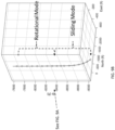
- the trajectory generator 20 determines the mode between the two survey points. If the angular difference ⁇ is smaller than a threshold value (e.g., 0.1 degrees), then the mode between the two survey points is classified as being a rotational mode (which refers to a mode where the drill bit moves forward with a substantially straight trajectory, with the drill bit rotating at a particular rotational rate, such as 25 rpm). If the angular difference ⁇ exceeds the threshold value, then the mode between the two survey points is classified as a sliding mode (which refers to a mode where the drill bit moves with a curved trajectory, and where the drill bit does not rotate).
- a threshold value e.g., 0.1 degrees
- mode between the two survey points is a rotational mode
- the A and I coordinates are calculated as being the same during the moving time, because the angular change of the unit attitude vector is smaller than the threshold (e.g., a threshold such as 0.1 degrees).
- the toolface angle T is not calculated because the toolface angle is kept the same during the sliding mode.
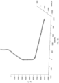
- FIG. 7A is a graph depicting the realization of the angular rates as a function of time in a rotational drilling mode with a normalized double-Gaussian distribution function.
- FIG. 7B is a graph of the angular difference between the attitude at a first station and the attitude at a second station as a function of time. Accordingly, each of the trajectory coordinates can be considered as being associated with a timestamp.
- FIG. 8A is a graph depicting azimuth, inclination, and toolface (AIT) coordinates as a function of time, as generated according to one example of the present invention.
- FIG. 8B is an enlargement of the portion of FIG. 8A indicated with an ellipse. Accordingly, each of the trajectory coordinates can be considered as being associated with a timestamp.
- a "sanity check" computation is performed on the generated attitude (AIT) coordinates to ensure that they are reasonable and/or well-defined.
- the angular coordinates would be ill-defined if the inclination (I) coordinate satisfied the relationship sin( I ) ⁇ 0, because, in any attitude that is pointing straight down or straight up, the azimuth (A) angle becomes ill-defined.
- FIG. 10 is a functional block diagram illustrating components of a sensor output generator 40 according to one example of the present invention.
- the sensor output generator 300 includes an input module that is provided with the generated trajectory from the trajectory generator 20 along with the geodetic parameters 41.
- the geodetic parameters 41 include magnetic strength (Bt) and the dip and declination angles, as described above.
- the generated trajectory and the geodetic parameters are used to generate the outputs of accelerometers 43, gyroscopes 45, and magnetometers 47 to generate nine-degree-of-freedom (9-DOF) sensor data.
- This generated sensor data does not include noise, and merely represents an idealized output from the sensor output generators.
- the output generators 43 generate three axis data at the navigation frame f ib n , as illustrated in FIG. 10 .
- the three axis data at the navigation frame f ib n can be generated in accordance with the following equation: f ib n ⁇ V ⁇ sb s + 2 ⁇ ie n V eb s ⁇ g b n N s E s D s
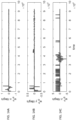
- FIGS. 11A, 11B, and 11C are graphs depicting acceleration vectors, with respect to the navigation frame, generated by a sensor output generator 40 according to one example of the present invention.
- FIGS. 12A, 12B, and 12C are graphs depicting 3-axis accelerometer data generated by a sensor output generator 40, with respect to the body frame, without added noise, according to one example of the present invention.
- FIGS. 14A, 14B, and 14C are graphs depicting 3-axis gyroscopic data generated by a sensor output generator 40, with respect to the inertial frame ⁇ ib b , without added noise, according to one example of the present invention.
- the outputs of the generated three axis magnetometer data can then be converted to the body frame B ib b in accordance with the relationship: B ib b ⁇ C n b B N B E B D ′
- FIGS. 15A, 15B, and 15C are graphs depicting 3-axis magnetometer data generated by a sensor output generator 40, in the body frame without added noise, according to one example of the present invention.
- the generated IMU data is verified by comparing the calculated positional coordinates from the trajectory generator 20 with the output of an inertial navigation system (INS) that is supplied with the generated IMU data.
- INS inertial navigation system
- INS model is described in Paul D. Groves, Principles of GNSS, Inertial and Multisensor Integrated Navigation Systems, Artech House (2001)
- FIGS. 16A , 16B , and 16C are graphs depicting differences between the north, east, and depth positional differences between the trajectory generator and the output of an inertial navigation system (INS) that is supplied with generated IMU sensor data according to one example of the present invention. As shown in FIGS. 16A , 16B , and 16C , there is a less than 20 foot error at the end of the generated thousands of feet of drilling over a generated 20 hours.
- INS inertial navigation system
- the present invention relates to a noise generator module 60 configured to add noise to the generated IMU data in accordance with noise models for the various sensors of the IMU.
- sensor noise due to drilling dynamics (e.g., linear and torsional vibration, shock, temperature swings and temperature gradients).
- drilling dynamics e.g., linear and torsional vibration, shock, temperature swings and temperature gradients.
- sensor noise due to drilling dynamics (e.g., linear and torsional vibration, shock, temperature swings and temperature gradients).
- drilling dynamics e.g., linear and torsional vibration, shock, temperature swings and temperature gradients.
- the noise profile added to the synthesized IMU signal is shaped by characterization parameters determined from measurements, allowing the sensor output generator 40 to produce, with the noise generator module 60, realistic IMU signals.
- An inertial sensor's output contains a multitude of noise components which affect the accuracy of measurements.
- Various analysis methods exist to identify and characterize these noise components such as Power Spectral Density and Allan Deviation analysis (see, e.g., Allan, D. W., "Statistics of atomic frequency standards," Proceedings of the IEEE, vol. 54, no. 2, pp. 221-230, Feb. 1966 .).
- Allan Deviation analysis See, e.g., Allan, D. W., "Statistics of atomic frequency standards," Proceedings of the IEEE, vol. 54, no. 2, pp. 221-230, Feb. 1966 .
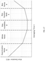
- Allan deviation analysis is performed on the output of a sensor under static conditions, producing a curve of Allan Deviation versus averaging time, as shown in FIG. 17 , which is an Allan deviation curve characterizing the different components of noise in a sensor output.
- Different types of noise are identified based on the slope at different sections of the curve and noise coefficients, including quantization noise (Q), white noise(N), bias instability (B), bias random walk (K), and bias ramp (R) are derived according to El-Sheimy, Naser, Haiying Hou, and Xiaoji Niu. "Analysis and modeling of inertial sensors using Allan variance.” IEEE Transactions on Instrumentation and Measurement 57.1 (2008): 140-149 . These coefficients are then used to generate the individual noise components which are summed to produce a composite noise signal that is added to the clean sensor signal in the generator, as shown in FIG. 18 .
- the IMU When the drill bit is operating, the IMU is subject to e.g. mechanical vibrations which are picked up by its sensors. To generate this type of noise, real field data is processed to compute the typical noise spectrum for each drilling mode (rotating and sliding).
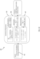
- FIG. 18 is a block diagram depicting a downhole IMU noise generator 60 according to the present invention.
- the IMU noise generator 60 includes sensor noise generators 62, including quantization noise (Q), white noise (N), bias instability (B), bias random walk (K), and bias ramp (R) noise generators which are summed to form a composite sensor noise.
- the composite sensor noise 63 is added to the clean generated sensor signal 61 generated by the sensor output generator 40 to generate a noisy generated sensor signal 64.
- the downhole IMU noise generator 60 includes a drilling noise component 65.
- the drilling noise component 65 may include three types of noise corresponding to the three drilling modes: survey mode (e.g., a mode where the drill bit is stationary and therefore not drilling, resulting in no drilling noise), a rotating mode (or rotational mode), and a sliding mode. Because the drill bit can only operate in one of these modes at a time, a mode-based selector switch 66 is used to select between the different noise generators in accordance with the current mode of the generated IMU (e.g., for data points corresponding to a rotational mode, the selector switch is set to supply the rotating mode noise, and for data points corresponding to a sliding mode, the selector switch is set to supply the sliding mode noise).
- the additional noise 67 generated by the drilling noise component is added to the noisy generated sensor signal 64 to generate a drilling sensor signal 68.
- FIG. 19 is a flowchart illustrating the computation of position and attitude profiles to be twice differentiable according to one example of the present invention.
- the IMU generator 10 generates an acceleration profile 1910 (e.g., including a positive Gaussian 1912 and a negative Gaussian 1914 followed by a dwell time 1916, where the dwell time represents time spent at the survey points).
- the acceleration is normalized so that, when it is twice integrated (once to generate velocity and rate profiles 1920, and a second time to generate position and attitude profiles 1930), it creates a position/attitude profile that rises to a value of 1. This acceleration can then be scaled to the desired position or angle.
- FIG. 20 is a flowchart illustrating the computation of a current position and attitude using a lookup table according to one example of the present invention.
- a lookup table 2010 is implemented that uses the current time to compute the correct output from the position and attitude profiles 1930.
- the current position and attitudes 2020 are then fed into a kinematic generator (see, e.g., FIG. 2B ) to generate specific forces, angular rates, and magnetic field measurements.
- examples of the present invention provide systems and methods for generating the output of a downhole inertial measurement unit (IMU).
- IMU downhole inertial measurement unit
- the downhole inertial measurement unit is implemented on a real-time target machine and is used as hardware-in-the-loop (HIL).
- a real-time target machine is a computer designed and built specifically for a particular application (such as testing an autonomous guidance while drilling system) and may include field programmable gate arrays (FPGAs), vector processors, memory and the like such that the machine will complete all computations to support testing of an IMU in a finite amount of time.
- FPGAs field programmable gate arrays
- examples of the present invention can be used to provide simulated measurements of acceleration, orientation, and magnetic field to the IMU such that the AGWD controller generates commands to the drill head.
- Examples of the present invention simulate accelerometers, gyroscopes and magnetometers to support hardware-in-the-loop (HIL) simulation.
- the real-time target machine is configured to send commands to a motion controller to control a nonmagnetic motion simulator apparatus. Accordingly, examples of the present invention may be used to test the operation of an autonomous guidance while drilling (AGWD) system that is mounted in the simulator apparatus.
- AGWD autonomous guidance while drilling
- pressure data and measured depth data can also be generated in accordance with the geodetic data. More specifically, in some examples pressure data is generated in accordance with depth (e.g., pressure increases with depth) and may also be adjusted based on local conditions (e.g., characteristics of the particular subsurface structures captured through geological studies).
- processing unit may be implemented with logic gates, or with any other example of a processing unit or processor.
- processing unit or “processor” is used herein to include any combination of hardware, firmware, and software, employed to process data or digital signals.
- Processing unit hardware may include, for example, application specific integrated circuits (ASICs), general purpose or special purpose central processing units (CPUs), digital signal processors (DSPs), graphics processing units (GPUs), and programmable logic devices such as field programmable gate arrays (FPGAs).
- ASICs application specific integrated circuits
- CPUs general purpose or special purpose central processing units
- DSPs digital signal processors
- GPUs graphics processing units
- FPGAs field programmable gate arrays
- FIG. 21 is a block diagram illustrating a processing system, a processor, or a portion of a processing system or processor, referred to herein as a computer system, used in conjunction with at least one example of the present invention.
- Exemplary computer system 1200 in accordance with an example is shown in FIG. 21 .
- Exemplary computer system 1200 is configured to perform calculations, processes, operations, and/or functions associated with a program or algorithm.
- certain processes and steps discussed herein are realized as a series of instructions (e.g., software program) that reside within computer readable memory units and are executed by one or more processors of exemplary computer system 1200. When executed, the instructions cause exemplary computer system 1200 to perform specific actions and exhibit specific behavior, such as described herein.
- Exemplary computer system 1200 may include an address/data bus 1210 that is configured to communicate information. Additionally, one or more data processing unit, such as processor 1220, are coupled with address/data bus 1210. Processor 1220 is configured to process information and instructions. In an example, processor 1220 is a microprocessor. Alternatively, processor 1220 may be a different type of processor such as a parallel processor, or a field programmable gate array.
- Exemplary computer system 1200 is configured to utilize one or more data storage units.
- Exemplary computer system 1200 may include a volatile memory unit 1230 (e.g., random access memory (“RAM”), static RAM, dynamic RAM, etc.) coupled with address/data bus 1210, wherein volatile memory unit 1230 is configured to store information and instructions for processor 1220.
- volatile memory unit 1230 e.g., random access memory (“RAM”), static RAM, dynamic RAM, etc.
- Exemplary computer system 1200 further may include a non-volatile memory unit 1240 (e.g., read-only memory (“ROM”), programmable ROM (“PROM”), erasable programmable ROM (“EPROM”), electrically erasable programmable ROM “EEPROM”), flash memory, etc.) coupled with address/data bus 1210, wherein non-volatile memory unit 1240 is configured to store static information and instructions for processor 1220.
- exemplary computer system 1200 may execute instructions retrieved from an online data storage unit such as in "Cloud” computing.
- exemplary computer system 1200 also may include one or more interfaces, such as interface 1250, coupled with address/data bus 1210.
- the one or more interfaces are configured to enable exemplary computer system 1200 to interface with other electronic devices and computer systems.
- the communication interfaces implemented by the one or more interfaces may include wireline (e.g., serial cables, modems, network adaptors, etc.) and/or wireless (e.g., wireless modems, wireless network adaptors, etc.) communication technology.
- exemplar computer system 1200 may include an input device 1260 coupled with address/data bus 1210, wherein input device 1260 is configured to communicate information and command selections to processor 1220.
- input device 1260 is an alphanumeric input device, such as a keyboard, that may include alphanumeric and/or function keys.
- input device 1260 may be an input device other than an alphanumeric input device.
- exemplar computer system 1200 may include a cursor control device 1270 coupled with address/data bus 1210, wherein cursor control device 1270 is configured to communicate user input information and/or command selections to processor 1220.
- cursor control device 1270 is implemented using a device such as a mouse, a track-ball, a track-pad, an optical tracking device, or a touch screen.
- cursor control device 1270 is directed and/or activated via input from input device 1260, such as in response to the use of special keys and key sequence commands associated with input device 1260.
- cursor control device 1270 is configured to be directed or guided by voice commands.
- exemplary computer system 1200 further may include one or more optional computer usable data storage devices, such as storage device 1280, coupled with address/data bus 1210.
- Storage device 1280 is configured to store information and/or computer executable instructions.
- storage device 1280 is a storage device such as a magnetic or optical disk drive (e.g., hard disk drive (“HDD”), floppy diskette, compact disk read only memory (“CD-ROM”), digital versatile disk (“DVD”)).
- HDD hard disk drive
- CD-ROM compact disk read only memory
- DVD digital versatile disk
- a display device 1290 is coupled with address/data bus 1210, wherein display device 1290 is configured to display video and/or graphics.
- display device 1290 may include a cathode ray tube (“CRT”), liquid crystal display (“LCD”), field emission display (“FED”), plasma display or any other display device suitable for displaying video and/or graphic images and alphanumeric characters recognizable to a user.
- CTR cathode ray tube
- LCD liquid crystal display
- FED field emission display
- plasma display any other display device suitable for displaying video and/or graphic images and alphanumeric characters recognizable to a user.
- Exemplary computer system 1200 is presented herein as an exemplary computing environment in accordance with an example.
- exemplary computer system 1200 is not strictly limited to being a computer system.
- exemplary computer system 1200 represents a type of data processing analysis that may be used in accordance with various examples described herein.
- other computing systems may also be implemented.
- one or more operations of various examples of the present technology are controlled or implemented using computer-executable instructions, such as program modules, being executed by a computer.
- program modules include routines, programs, objects, components and/or data structures that are configured to perform particular tasks or implement particular abstract data types.
- an example provides that one or more aspects of the present technology are implemented by utilizing one or more distributed computing environments, such as where tasks are performed by remote processing devices that are linked through a communications network, or such as where various program modules are located in both local and remote computer-storage media including memory-storage devices.
Landscapes
- Engineering & Computer Science (AREA)
- Geology (AREA)
- Life Sciences & Earth Sciences (AREA)
- Mining & Mineral Resources (AREA)
- Physics & Mathematics (AREA)
- General Life Sciences & Earth Sciences (AREA)
- Fluid Mechanics (AREA)
- Environmental & Geological Engineering (AREA)
- Geochemistry & Mineralogy (AREA)
- Geophysics (AREA)
- Electromagnetism (AREA)
- Navigation (AREA)
- Radar, Positioning & Navigation (AREA)
- Remote Sensing (AREA)
- Geophysics And Detection Of Objects (AREA)
- Automation & Control Theory (AREA)
- General Physics & Mathematics (AREA)
- Gyroscopes (AREA)
Claims (12)
- Procédé mis en œuvre sur un ordinateur pour simuler une sortie d'une unité de mesure inertielle, IMU (Inertial Measure Unit), de forage, en tant que moyen de vérifier et de valider que les capteurs de l'IMU de forage fonctionnent correctement, et pour améliorer plus avant des algorithmes mis en œuvre, l'IMU de forage étant composée de boîtiers de capteurs qui incluent des accéléromètres, des gyroscopes, des magnétomètres et des capteurs de pression destinés à fournir des informations en temps réel pour permettre un guidage autonome en cours de forage (Autonomous Guidance While Drilling), un système de guidage autonome en cours de forage consistant en un système qui estime la trajectoire du trou de forage en temps réel et fournit un guidage et une navigation autonomes en temps réel pour un ensemble de fond de puits, les algorithmes mis en œuvre consistant en des algorithmes de navigation pour contrôler le système de guidage autonome en cours de forage, le procédé comprenantune génération d'une trajectoire (200) entre une pluralité de points de sondage de données de puits planifié (12) en tant que fonction temporelle, les données de puits planifié comprenant une pluralité de coordonnées tridimensionnelles correspondant aux points de sondage d'un puits planifié souterrain, la trajectoire comprenant une pluralité de coordonnées de trajectoire entre des consécutifs des points de sondage ;une génération, par simulation, de données de capteur (400) pour chacune des coordonnées de trajectoire en tant que fonction temporelle reposant sur des paramètres de référence géodésiques (41), les données de capteur générées comprenant : une sortie d'accéléromètre générée (43) ; une sortie gyroscopique générée (45) ; et une sortie de magnétomètre générée (47) ;une réception de paramètres de bruit de capteur ;un ajout de bruit de capteur à la sortie d'accéléromètre sur trois axes générée, la sortie gyroscopique générée et la sortie de magnétomètre générée ; etune génération en sortie, consécutivement à l'étape d'ajout de bruit de capteur, de la sortie d'accéléromètre générée ; la sortie de gyroscope générée ; et la sortie de magnétomètre générée en tant que fonction temporelle comme sortie simulée de l'IMU de forage.
- Le procédé mis en œuvre sur un ordinateur de la revendication 1, dans lequel la génération de la trajectoire entre des points de sondage est exécutée selon un pas temporel de 1 par seconde à 1000 par seconde.
- Le procédé mis en œuvre sur un ordinateur de la revendication 1, dans lequel chacune des coordonnées de trajectoire générées comprend une position tridimensionnelle, une orientation tridimensionnelle et un horodatage.
- Le procédé mis en œuvre sur un ordinateur de la revendication 3, dans lequel chaque orientation tridimensionnelle comprend un angle azimutal, un angle d'inclinaison et un angle de face d'outil d'une mèche de forage.
- Le procédé mis en œuvre sur un ordinateur de la revendication 3, comprenant en outre :une génération de la sortie d'accéléromètre conformément aux positions tridimensionnelles et aux horodatages des coordonnées de trajectoire ;une génération de la sortie gyroscopique conformément à l'orientation tridimensionnelle et aux horodatages des coordonnées de trajectoire ; etune génération de la sortie de magnétomètre d'axe conformément :aux paramètres de référence géodésiques ; etaux positions tridimensionnelles et aux horodatages des coordonnées de trajectoire.
- Le procédé mis en œuvre sur un ordinateur de la revendication 5, dans lequel le calcul de la sortie d'accéléromètre générée comprend une conversion de données d'accéléromètre générées d'un cadre de navigation vers un châssis de mèche de forage,dans lequel le calcul de la sortie gyroscopique générée comprend une conversion de données gyroscopiques générées du cadre de navigation vers le châssis de la mèche de forage, etdans lequel le calcul de la sortie de magnétomètre générée comprend une conversion d'une sortie de magnétomètre générée du cadre de navigation vers le châssis de la mèche de forage.
- Le procédé mis en œuvre sur un ordinateur de la revendication 1, dans lequel le bruit de capteur comprend au moins un de :bruit de quantification (Q) ;bruit blanc (N) ;instabilité du biais (B) ;marche aléatoire à angle (K) ; etaccélération du biais (R).
- Le procédé mis en œuvre par un ordinateur de la revendication 1, comprenant en outre, entre chaque paire consécutive de points de sondage :une détermination que la trajectoire entre la paire consécutive de points de sondage est une trajectoire de mode de rotation ou une trajectoire de mode de coulissement ;en réaction à une détermination de la trajectoire de mode de rotation, un ajout de bruit de forage de mode de rotation à la sortie d'accéléromètre générée, la sortie gyroscopique générée et la sortie de magnétomètre générée ; eten réaction à une détermination de la trajectoire de mode de coulissement, un ajout de bruit de forage de mode de coulissement à la sortie d'accéléromètre générée, la sortie gyroscopique générée et la sortie de magnétomètre générée.
- Le procédé mis en œuvre sur un ordinateur de la revendication 1, comprenant en outre une vérification de la sortie générée de l'IMU par :une fourniture de la sortie d'accéléromètre sur trois axes générée, la sortie gyroscopique sur trois axes générée et la sortie de magnétomètre sur trois axes générée à un système de navigation inertielle, INS (Inertial Navigation System), pour générer une trajectoire de système INS ; etune vérification de la sortie générée de l'IMU lorsqu'une différence entre la trajectoire de système INS et la trajectoire calculée issue des données de puits planifié est inférieure à une valeur de seuil.
- Support de stockage non transitoire lisible par un ordinateur ayant stockées en son sein des instructions qui, lorsqu'exécutées par un processeur, font exécuter au processeur le procédé de la revendication 1.
- Système informatique (1200) pour générer une sortie de données d'une unité de mesure inertielle, IMU (Inertial Measure Unit), de forage, le système comprenant :un processeur (1220) ; etune mémoire (1240) stockant des instructions qui, lorsqu'exécutées par le processeur, font exécuter au processeur le procédé de la revendication 1.
- Le système informatique de la revendication 11, dans lequel le système informatique est mis en œuvre sur une machine cible en temps réel et utilisé comme simulation HITL (Hardware-In-The-Loop).
Applications Claiming Priority (2)
| Application Number | Priority Date | Filing Date | Title |
|---|---|---|---|
| US201762525051P | 2017-06-26 | 2017-06-26 | |
| PCT/US2018/039534 WO2019005819A1 (fr) | 2017-06-26 | 2018-06-26 | Système et procédé de production de sortie d'unité de mesure inertielle de fond de trou |
Publications (3)
| Publication Number | Publication Date |
|---|---|
| EP3645836A1 EP3645836A1 (fr) | 2020-05-06 |
| EP3645836A4 EP3645836A4 (fr) | 2021-04-07 |
| EP3645836B1 true EP3645836B1 (fr) | 2025-02-26 |
Family
ID=64691561
Family Applications (1)
| Application Number | Title | Priority Date | Filing Date |
|---|---|---|---|
| EP18823984.2A Active EP3645836B1 (fr) | 2017-06-26 | 2018-06-26 | Système et procédé de production de sortie d'unité de mesure inertielle de fond de trou |
Country Status (4)
| Country | Link |
|---|---|
| US (1) | US11066923B2 (fr) |
| EP (1) | EP3645836B1 (fr) |
| CN (1) | CN110799727B (fr) |
| WO (1) | WO2019005819A1 (fr) |
Families Citing this family (20)
| Publication number | Priority date | Publication date | Assignee | Title |
|---|---|---|---|---|
| US9297205B2 (en) | 2011-12-22 | 2016-03-29 | Hunt Advanced Drilling Technologies, LLC | System and method for controlling a drilling path based on drift estimates |
| US8210283B1 (en) | 2011-12-22 | 2012-07-03 | Hunt Energy Enterprises, L.L.C. | System and method for surface steerable drilling |
| US8596385B2 (en) | 2011-12-22 | 2013-12-03 | Hunt Advanced Drilling Technologies, L.L.C. | System and method for determining incremental progression between survey points while drilling |
| US11085283B2 (en) | 2011-12-22 | 2021-08-10 | Motive Drilling Technologies, Inc. | System and method for surface steerable drilling using tactical tracking |
| US9428961B2 (en) | 2014-06-25 | 2016-08-30 | Motive Drilling Technologies, Inc. | Surface steerable drilling system for use with rotary steerable system |
| US11106185B2 (en) | 2014-06-25 | 2021-08-31 | Motive Drilling Technologies, Inc. | System and method for surface steerable drilling to provide formation mechanical analysis |
| SE538872C2 (en) * | 2015-05-04 | 2017-01-17 | Lkab Wassara Ab | Gyro-based surveying tool and method for surveying |
| US11933158B2 (en) | 2016-09-02 | 2024-03-19 | Motive Drilling Technologies, Inc. | System and method for mag ranging drilling control |
| US11268810B2 (en) * | 2019-07-10 | 2022-03-08 | United States Of America As Represented By The Secretary Of The Navy | Angle random walk minimization for frequency modulated gyroscopes |
| KR102105516B1 (ko) * | 2020-01-28 | 2020-05-29 | (주)지오투정보기술 | Gis를 기반으로 측량하는 측지측량시스템 |
| US12006793B2 (en) | 2020-01-30 | 2024-06-11 | Advanced Upstream Ltd. | Devices, systems, and methods for selectively engaging downhole tool for wellbore operations |
| CN120889563A (zh) | 2020-01-30 | 2025-11-04 | 先进上游有限公司 | 用于井筒操作的选择性接合井下工具的装置、系统和方法 |
| US12023769B2 (en) | 2020-02-14 | 2024-07-02 | Caterpillar Global Mining Llc. | System and method for automated drilling activity monitoring |
| US11891891B2 (en) * | 2020-07-28 | 2024-02-06 | Geodynamics, Inc. | Switch device with non-addressable scheme for wellbore operations |
| CN114001757B (zh) * | 2021-11-05 | 2023-05-12 | 北京航空航天大学 | 一种磁力计零偏校准方法 |
| CA3156467A1 (fr) * | 2022-04-25 | 2023-10-25 | Hazen International Energy Services Inc. | Appareil et methode de telemetrie magnetique deployee par drone |
| US12276183B2 (en) * | 2022-08-03 | 2025-04-15 | Probe Technology Services, Inc. | Perforating-gun initiator circuit |
| CN115597619B (zh) * | 2022-09-30 | 2026-04-14 | 阿波罗智能技术(北京)有限公司 | 车辆的路径规划方法、装置、电子设备及自动驾驶车辆 |
| CN117090558B (zh) * | 2023-08-16 | 2024-08-06 | 中国石油天然气集团有限公司 | 救援井轨迹调整方法及装置 |
| CN120926965B (zh) * | 2025-10-13 | 2025-12-09 | 中国石油集团渤海钻探工程有限公司 | 一种钻具回转体角速度测量方法、系统、设备及存储介质 |
Family Cites Families (37)
| Publication number | Priority date | Publication date | Assignee | Title |
|---|---|---|---|---|
| US4454756A (en) * | 1982-11-18 | 1984-06-19 | Wilson Industries, Inc. | Inertial borehole survey system |
| GB2351807B (en) * | 1999-07-01 | 2001-08-22 | Schlumberger Holdings | Reverse inertial navigation method for high precision wellbore surveying |
| DE19950340B4 (de) * | 1999-10-19 | 2005-12-22 | Halliburton Energy Services, Inc., Houston | Verfahren und Vorrichtung zum Messen des Verlaufs eines Bohrlochs |
| US6405808B1 (en) * | 2000-03-30 | 2002-06-18 | Schlumberger Technology Corporation | Method for increasing the efficiency of drilling a wellbore, improving the accuracy of its borehole trajectory and reducing the corresponding computed ellise of uncertainty |
| PY0111577A (es) | 2000-05-23 | 2017-01-02 | Idenix Cayman Ltd | Métodos y composiciones para el tratamiento del virus de la hepatitis c |
| AP2006003708A0 (en) | 2000-05-26 | 2006-08-31 | Idenix Cayman Ltd | Methods and compositions for treating flavivirusesand pestiviruses |
| AU2001249000A1 (en) * | 2000-10-27 | 2002-05-06 | Vermeer Manufacturing Company | Solid-state inertial navigation control system for a horizontal drilling machine |
| US6668465B2 (en) * | 2001-01-19 | 2003-12-30 | University Technologies International Inc. | Continuous measurement-while-drilling surveying |
| US6823602B2 (en) * | 2001-02-23 | 2004-11-30 | University Technologies International Inc. | Continuous measurement-while-drilling surveying |
| AU2002330154A1 (en) | 2001-09-28 | 2003-04-07 | Centre National De La Recherche Scientifique | Methods and compositions for treating hepatitis c virus using 4'-modified nucleosides |
| AU2002357415A1 (en) * | 2002-11-22 | 2004-06-18 | Reduct | Method for determining a track of a geographical trajectory |
| CA2725717C (fr) * | 2003-01-31 | 2014-04-15 | Weatherford/Lamb, Inc. | Appareil et procedes permettant de forer un puits utilisant un cuvelage |
| GB2415972A (en) * | 2004-07-09 | 2006-01-11 | Halliburton Energy Serv Inc | Closed loop steerable drilling tool |
| CN101263276B (zh) * | 2005-08-04 | 2011-12-21 | 英特里瑟夫国际控股有限公司 | 用于井筒遥测系统的界面和方法 |
| NO326572B1 (no) * | 2007-04-16 | 2009-01-12 | Marine Cybernetics As | System og fremgangsmate for testing av borereguleringssystemer |
| MX341532B (es) * | 2007-08-15 | 2016-08-24 | Schlumberger Tech B V * | Sistema y metodo para perforar direccionalmente un pozo con un sistema de perforacion giratorio. |
| US7886844B2 (en) * | 2007-11-12 | 2011-02-15 | Schlumberger Technology Corporation | Borehole survey method and apparatus |
| US7823661B2 (en) * | 2008-06-24 | 2010-11-02 | Mintchev Martin P | In-drilling alignment |
| US8065087B2 (en) * | 2009-01-30 | 2011-11-22 | Gyrodata, Incorporated | Reducing error contributions to gyroscopic measurements from a wellbore survey system |
| CN101493008A (zh) * | 2009-02-17 | 2009-07-29 | 北京六合伟业科技有限公司 | 基于mems器件的捷联惯性导航陀螺测斜仪 |
| CN101876244A (zh) * | 2010-06-03 | 2010-11-03 | 西安思坦仪器股份有限公司 | 一种惯性测量单元以及动力调谐陀螺连续测斜仪 |
| US20150247729A1 (en) * | 2012-09-04 | 2015-09-03 | Deborah Meduna | System and method for device bearing estimation |
| US10274509B1 (en) * | 2014-04-09 | 2019-04-30 | Inertialwave | Inertial motion tracking device |
| US20170218747A1 (en) * | 2014-08-06 | 2017-08-03 | Schlumberger Technology Corporation | Determining expected sensor values for drilling to monitor the sensor |
| MX383426B (es) * | 2014-09-10 | 2025-03-14 | Fracture Id Inc | Aparato y metodo que utiliza las mediciones tomadas durante la perforacion para trazar un mapa de los limites mecanicos y las propiedades mecanicas de la roca a lo largo del pozo |
| CA2967324C (fr) * | 2014-10-02 | 2019-03-12 | Todd W. Benson | Systeme de forage orientable de surface destine a etre utilise avec un systeme rotary orientable |
| KR101684005B1 (ko) * | 2014-11-25 | 2016-12-08 | 한국과학기술원 | 지하 위치인식 방법 및 시스템 |
| SG11201707441XA (en) * | 2015-03-12 | 2017-10-30 | Transocean Sedco Forex Ventures Ltd | Dynamic positioning (dp) drive-off (do) mitigation with inertial navigation system |
| SE538872C2 (en) * | 2015-05-04 | 2017-01-17 | Lkab Wassara Ab | Gyro-based surveying tool and method for surveying |
| US20160363460A1 (en) * | 2015-06-12 | 2016-12-15 | 7725965 Canada Inc. | Orientation model for inertial devices |
| CN105041303B (zh) * | 2015-07-27 | 2018-10-02 | 电子科技大学 | 钻井液随钻数据传输系统的泵冲干扰信号消除方法 |
| CN108603405A (zh) * | 2015-09-28 | 2018-09-28 | 赫尔实验室有限公司 | 利用多站分析进行的实时轨迹估计 |
| CN205232235U (zh) * | 2015-11-20 | 2016-05-11 | 宝鸡文理学院 | 声波信号检测装置 |
| US9909877B2 (en) * | 2016-06-06 | 2018-03-06 | Honeywell International Inc. | Heading inconsistency mitigation for inertial navigation using low-performance inertial measurement units with relative aiding |
| CN105909238B (zh) * | 2016-06-07 | 2023-04-25 | 北京科技大学 | 一种惯性测量单元及单轴伺服连续测斜方法 |
| EP3267152B1 (fr) * | 2016-07-05 | 2019-11-13 | The Boeing Company | Aides à la navigation pour systèmes aériens télépilotés dans un environnement sans gps |
| US10408622B2 (en) * | 2016-11-29 | 2019-09-10 | Hrl Laboratories, Llc | System for incremental trajectory estimation based on real time inertial sensing |
-
2018
- 2018-06-26 EP EP18823984.2A patent/EP3645836B1/fr active Active
- 2018-06-26 WO PCT/US2018/039534 patent/WO2019005819A1/fr not_active Ceased
- 2018-06-26 US US16/018,695 patent/US11066923B2/en active Active
- 2018-06-26 CN CN201880042718.3A patent/CN110799727B/zh active Active
Also Published As
| Publication number | Publication date |
|---|---|
| US20180371894A1 (en) | 2018-12-27 |
| WO2019005819A1 (fr) | 2019-01-03 |
| US11066923B2 (en) | 2021-07-20 |
| CN110799727B (zh) | 2023-06-27 |
| EP3645836A4 (fr) | 2021-04-07 |
| EP3645836A1 (fr) | 2020-05-06 |
| WO2019005819A4 (fr) | 2019-02-21 |
| CN110799727A (zh) | 2020-02-14 |
Similar Documents
| Publication | Publication Date | Title |
|---|---|---|
| US11066923B2 (en) | System and method for generating output of a downhole inertial measurement unit | |
| Noureldin et al. | Accuracy limitations of FOG-based continuous measurement-while-drilling surveying instruments for horizontal wells | |
| US8788249B2 (en) | Gyrocompass modeling and simulation system (GMSS) and method thereof | |
| US10323501B2 (en) | Method and apparatus for generating weighted average survey | |
| US10408622B2 (en) | System for incremental trajectory estimation based on real time inertial sensing | |
| CN111076717B (zh) | 基于全球地磁异常场的地磁辅助惯性导航仿真系统及方法 | |
| US10246988B2 (en) | Real-time trajectory estimation with multi-station analysis | |
| Wang et al. | Rotary in-drilling alignment using an autonomous MEMS-based inertial measurement unit for measurement-while-drilling processes | |
| CN102997913A (zh) | 用于确定物体姿态的方法及装置 | |
| EP3123209B1 (fr) | Gravimètre vectoriel absolu et procédés de mesure d'un vecteur de gravité absolu | |
| Wang et al. | A reduced inertial sensor system based on MEMS for wellbore continuous surveying while horizontal drilling | |
| CN120293159A (zh) | 基于多源数据的掘进装备自主导航定位方法及系统 | |
| CN106643726A (zh) | 一种统一惯性导航解算方法 | |
| Weston et al. | New gyro while drilling technology delivers accurate azimuth and real-time quality control for all well trajectories | |
| JP2013122384A (ja) | カルマンフィルタ、及び、状態推定装置 | |
| Binder | Construction of a geographically oriented horizon trihedron in gyroscopic orientation systems intended to aid navigation dead reckoning part 1. Gyroscopic orientation with a correctable pendulum. Implementation in a free gyroscope | |
| Ramadass et al. | A modeling tool for sensor selection for inertial navigation systems used in underwater vehicles | |
| Chao et al. | An innovative MEMS-based MWD method for directional drilling | |
| MORITA et al. | Hayabusa descent navigation based on accurate landmark tracking scheme | |
| ElGizawy et al. | Continuous wellbore surveying while drilling utilizing MEMS gyroscopes based on Kalman filtering | |
| Cheng et al. | Modeling and simulation of low-cost integrated navigation system on vehicle | |
| Chao et al. | Continuous measurement-while-drilling surveying system utilizing low-cost SINS | |
| Weston et al. | New Gyro Drilling Technology Delivers Accurate Azimuth and Real Time Quality Control for All Well Trajectories | |
| Noureldin et al. | Measurement-while-drilling surveying of near-vertical wells and in sections of multi-well structure using FOG-based INS | |
| Cloutier | Experimental feasibility of the in-drilling alignment method for INS-based measurement-while-drilling |
Legal Events
| Date | Code | Title | Description |
|---|---|---|---|
| STAA | Information on the status of an ep patent application or granted ep patent |
Free format text: STATUS: THE INTERNATIONAL PUBLICATION HAS BEEN MADE |
|
| PUAI | Public reference made under article 153(3) epc to a published international application that has entered the european phase |
Free format text: ORIGINAL CODE: 0009012 |
|
| STAA | Information on the status of an ep patent application or granted ep patent |
Free format text: STATUS: REQUEST FOR EXAMINATION WAS MADE |
|
| 17P | Request for examination filed |
Effective date: 20191203 |
|
| AK | Designated contracting states |
Kind code of ref document: A1 Designated state(s): AL AT BE BG CH CY CZ DE DK EE ES FI FR GB GR HR HU IE IS IT LI LT LU LV MC MK MT NL NO PL PT RO RS SE SI SK SM TR |
|
| AX | Request for extension of the european patent |
Extension state: BA ME |
|
| DAV | Request for validation of the european patent (deleted) | ||
| DAX | Request for extension of the european patent (deleted) | ||
| A4 | Supplementary search report drawn up and despatched |
Effective date: 20210309 |
|
| RIC1 | Information provided on ipc code assigned before grant |
Ipc: E21B 7/04 20060101ALI20210302BHEP Ipc: E21B 47/024 20060101AFI20210302BHEP Ipc: E21B 47/09 20120101ALI20210302BHEP Ipc: E21B 47/022 20120101ALI20210302BHEP Ipc: E21B 41/00 20060101ALI20210302BHEP |
|
| RIN1 | Information on inventor provided before grant (corrected) |
Inventor name: CHANG, DAVID, T. Inventor name: PARAHIA, RAVIV Inventor name: NGUYEN, HUNG Inventor name: KABAKIAN, ADOUR V. Inventor name: WALTER, DAVID L. Inventor name: SORENSON, LOGAN D. Inventor name: WANG, SHUOQIN |
|
| STAA | Information on the status of an ep patent application or granted ep patent |
Free format text: STATUS: EXAMINATION IS IN PROGRESS |
|
| 17Q | First examination report despatched |
Effective date: 20230406 |
|
| GRAP | Despatch of communication of intention to grant a patent |
Free format text: ORIGINAL CODE: EPIDOSNIGR1 |
|
| STAA | Information on the status of an ep patent application or granted ep patent |
Free format text: STATUS: GRANT OF PATENT IS INTENDED |
|
| INTG | Intention to grant announced |
Effective date: 20241014 |
|
| GRAS | Grant fee paid |
Free format text: ORIGINAL CODE: EPIDOSNIGR3 |
|
| P01 | Opt-out of the competence of the unified patent court (upc) registered |
Free format text: CASE NUMBER: APP_66738/2024 Effective date: 20241217 |
|
| GRAA | (expected) grant |
Free format text: ORIGINAL CODE: 0009210 |
|
| STAA | Information on the status of an ep patent application or granted ep patent |
Free format text: STATUS: THE PATENT HAS BEEN GRANTED |
|
| AK | Designated contracting states |
Kind code of ref document: B1 Designated state(s): AL AT BE BG CH CY CZ DE DK EE ES FI FR GB GR HR HU IE IS IT LI LT LU LV MC MK MT NL NO PL PT RO RS SE SI SK SM TR |
|
| REG | Reference to a national code |
Ref country code: GB Ref legal event code: FG4D |
|
| REG | Reference to a national code |
Ref country code: CH Ref legal event code: EP |
|
| REG | Reference to a national code |
Ref country code: DE Ref legal event code: R096 Ref document number: 602018079648 Country of ref document: DE |
|
| REG | Reference to a national code |
Ref country code: IE Ref legal event code: FG4D |
|
| REG | Reference to a national code |
Ref country code: NL Ref legal event code: MP Effective date: 20250226 |
|
| PG25 | Lapsed in a contracting state [announced via postgrant information from national office to epo] |
Ref country code: RS Free format text: LAPSE BECAUSE OF FAILURE TO SUBMIT A TRANSLATION OF THE DESCRIPTION OR TO PAY THE FEE WITHIN THE PRESCRIBED TIME-LIMIT Effective date: 20250526 |
|
| PG25 | Lapsed in a contracting state [announced via postgrant information from national office to epo] |
Ref country code: FI Free format text: LAPSE BECAUSE OF FAILURE TO SUBMIT A TRANSLATION OF THE DESCRIPTION OR TO PAY THE FEE WITHIN THE PRESCRIBED TIME-LIMIT Effective date: 20250226 |
|
| PG25 | Lapsed in a contracting state [announced via postgrant information from national office to epo] |
Ref country code: PL Free format text: LAPSE BECAUSE OF FAILURE TO SUBMIT A TRANSLATION OF THE DESCRIPTION OR TO PAY THE FEE WITHIN THE PRESCRIBED TIME-LIMIT Effective date: 20250226 |
|
| PGFP | Annual fee paid to national office [announced via postgrant information from national office to epo] |
Ref country code: DE Payment date: 20250627 Year of fee payment: 8 |
|
| PG25 | Lapsed in a contracting state [announced via postgrant information from national office to epo] |
Ref country code: ES Free format text: LAPSE BECAUSE OF FAILURE TO SUBMIT A TRANSLATION OF THE DESCRIPTION OR TO PAY THE FEE WITHIN THE PRESCRIBED TIME-LIMIT Effective date: 20250226 |
|
| REG | Reference to a national code |
Ref country code: LT Ref legal event code: MG9D |
|
| PG25 | Lapsed in a contracting state [announced via postgrant information from national office to epo] |
Ref country code: NO Free format text: LAPSE BECAUSE OF FAILURE TO SUBMIT A TRANSLATION OF THE DESCRIPTION OR TO PAY THE FEE WITHIN THE PRESCRIBED TIME-LIMIT Effective date: 20250526 Ref country code: IS Free format text: LAPSE BECAUSE OF FAILURE TO SUBMIT A TRANSLATION OF THE DESCRIPTION OR TO PAY THE FEE WITHIN THE PRESCRIBED TIME-LIMIT Effective date: 20250626 |
|
| PG25 | Lapsed in a contracting state [announced via postgrant information from national office to epo] |
Ref country code: NL Free format text: LAPSE BECAUSE OF FAILURE TO SUBMIT A TRANSLATION OF THE DESCRIPTION OR TO PAY THE FEE WITHIN THE PRESCRIBED TIME-LIMIT Effective date: 20250226 |
|
| PG25 | Lapsed in a contracting state [announced via postgrant information from national office to epo] |
Ref country code: HR Free format text: LAPSE BECAUSE OF FAILURE TO SUBMIT A TRANSLATION OF THE DESCRIPTION OR TO PAY THE FEE WITHIN THE PRESCRIBED TIME-LIMIT Effective date: 20250226 |
|
| PG25 | Lapsed in a contracting state [announced via postgrant information from national office to epo] |
Ref country code: LV Free format text: LAPSE BECAUSE OF FAILURE TO SUBMIT A TRANSLATION OF THE DESCRIPTION OR TO PAY THE FEE WITHIN THE PRESCRIBED TIME-LIMIT Effective date: 20250226 Ref country code: PT Free format text: LAPSE BECAUSE OF FAILURE TO SUBMIT A TRANSLATION OF THE DESCRIPTION OR TO PAY THE FEE WITHIN THE PRESCRIBED TIME-LIMIT Effective date: 20250626 |
|
| PG25 | Lapsed in a contracting state [announced via postgrant information from national office to epo] |
Ref country code: BG Free format text: LAPSE BECAUSE OF FAILURE TO SUBMIT A TRANSLATION OF THE DESCRIPTION OR TO PAY THE FEE WITHIN THE PRESCRIBED TIME-LIMIT Effective date: 20250226 Ref country code: GR Free format text: LAPSE BECAUSE OF FAILURE TO SUBMIT A TRANSLATION OF THE DESCRIPTION OR TO PAY THE FEE WITHIN THE PRESCRIBED TIME-LIMIT Effective date: 20250527 |
|
| REG | Reference to a national code |
Ref country code: AT Ref legal event code: MK05 Ref document number: 1770783 Country of ref document: AT Kind code of ref document: T Effective date: 20250226 |
|
| PG25 | Lapsed in a contracting state [announced via postgrant information from national office to epo] |
Ref country code: SE Free format text: LAPSE BECAUSE OF FAILURE TO SUBMIT A TRANSLATION OF THE DESCRIPTION OR TO PAY THE FEE WITHIN THE PRESCRIBED TIME-LIMIT Effective date: 20250226 |
|
| PG25 | Lapsed in a contracting state [announced via postgrant information from national office to epo] |
Ref country code: SM Free format text: LAPSE BECAUSE OF FAILURE TO SUBMIT A TRANSLATION OF THE DESCRIPTION OR TO PAY THE FEE WITHIN THE PRESCRIBED TIME-LIMIT Effective date: 20250226 |
|
| PG25 | Lapsed in a contracting state [announced via postgrant information from national office to epo] |
Ref country code: DK Free format text: LAPSE BECAUSE OF FAILURE TO SUBMIT A TRANSLATION OF THE DESCRIPTION OR TO PAY THE FEE WITHIN THE PRESCRIBED TIME-LIMIT Effective date: 20250226 |
|
| PG25 | Lapsed in a contracting state [announced via postgrant information from national office to epo] |
Ref country code: IT Free format text: LAPSE BECAUSE OF FAILURE TO SUBMIT A TRANSLATION OF THE DESCRIPTION OR TO PAY THE FEE WITHIN THE PRESCRIBED TIME-LIMIT Effective date: 20250226 |
|
| PG25 | Lapsed in a contracting state [announced via postgrant information from national office to epo] |
Ref country code: AT Free format text: LAPSE BECAUSE OF FAILURE TO SUBMIT A TRANSLATION OF THE DESCRIPTION OR TO PAY THE FEE WITHIN THE PRESCRIBED TIME-LIMIT Effective date: 20250226 |
|
| PG25 | Lapsed in a contracting state [announced via postgrant information from national office to epo] |
Ref country code: EE Free format text: LAPSE BECAUSE OF FAILURE TO SUBMIT A TRANSLATION OF THE DESCRIPTION OR TO PAY THE FEE WITHIN THE PRESCRIBED TIME-LIMIT Effective date: 20250226 Ref country code: CZ Free format text: LAPSE BECAUSE OF FAILURE TO SUBMIT A TRANSLATION OF THE DESCRIPTION OR TO PAY THE FEE WITHIN THE PRESCRIBED TIME-LIMIT Effective date: 20250226 |
|
| PG25 | Lapsed in a contracting state [announced via postgrant information from national office to epo] |
Ref country code: RO Free format text: LAPSE BECAUSE OF FAILURE TO SUBMIT A TRANSLATION OF THE DESCRIPTION OR TO PAY THE FEE WITHIN THE PRESCRIBED TIME-LIMIT Effective date: 20250226 |
|
| PG25 | Lapsed in a contracting state [announced via postgrant information from national office to epo] |
Ref country code: SK Free format text: LAPSE BECAUSE OF FAILURE TO SUBMIT A TRANSLATION OF THE DESCRIPTION OR TO PAY THE FEE WITHIN THE PRESCRIBED TIME-LIMIT Effective date: 20250226 |
|
| REG | Reference to a national code |
Ref country code: DE Ref legal event code: R097 Ref document number: 602018079648 Country of ref document: DE |
|
| PLBE | No opposition filed within time limit |
Free format text: ORIGINAL CODE: 0009261 |
|
| STAA | Information on the status of an ep patent application or granted ep patent |
Free format text: STATUS: NO OPPOSITION FILED WITHIN TIME LIMIT |
|
| REG | Reference to a national code |
Ref country code: CH Ref legal event code: L10 Free format text: ST27 STATUS EVENT CODE: U-0-0-L10-L00 (AS PROVIDED BY THE NATIONAL OFFICE) Effective date: 20260107 |
|
| REG | Reference to a national code |
Ref country code: CH Ref legal event code: H13 Free format text: ST27 STATUS EVENT CODE: U-0-0-H10-H13 (AS PROVIDED BY THE NATIONAL OFFICE) Effective date: 20260127 |
|
| PG25 | Lapsed in a contracting state [announced via postgrant information from national office to epo] |
Ref country code: MC Free format text: LAPSE BECAUSE OF FAILURE TO SUBMIT A TRANSLATION OF THE DESCRIPTION OR TO PAY THE FEE WITHIN THE PRESCRIBED TIME-LIMIT Effective date: 20250226 |
|
| 26N | No opposition filed |
Effective date: 20251127 |
|
| PG25 | Lapsed in a contracting state [announced via postgrant information from national office to epo] |
Ref country code: LU Free format text: LAPSE BECAUSE OF NON-PAYMENT OF DUE FEES Effective date: 20250626 |
|
| GBPC | Gb: european patent ceased through non-payment of renewal fee |
Effective date: 20250626 |
|
| REG | Reference to a national code |
Ref country code: BE Ref legal event code: MM Effective date: 20250630 |
|
| PG25 | Lapsed in a contracting state [announced via postgrant information from national office to epo] |
Ref country code: GB Free format text: LAPSE BECAUSE OF NON-PAYMENT OF DUE FEES Effective date: 20250626 |
|
| PG25 | Lapsed in a contracting state [announced via postgrant information from national office to epo] |
Ref country code: IE Free format text: LAPSE BECAUSE OF NON-PAYMENT OF DUE FEES Effective date: 20250626 |
|
| PG25 | Lapsed in a contracting state [announced via postgrant information from national office to epo] |
Ref country code: BE Free format text: LAPSE BECAUSE OF NON-PAYMENT OF DUE FEES Effective date: 20250630 |
|
| PG25 | Lapsed in a contracting state [announced via postgrant information from national office to epo] |
Ref country code: FR Free format text: LAPSE BECAUSE OF NON-PAYMENT OF DUE FEES Effective date: 20250630 |
|
| PG25 | Lapsed in a contracting state [announced via postgrant information from national office to epo] |
Ref country code: CH Free format text: LAPSE BECAUSE OF NON-PAYMENT OF DUE FEES Effective date: 20250630 |