EP3645908B1 - Isolateur de vibrations de fluide et d'élastomère - Google Patents
Isolateur de vibrations de fluide et d'élastomère Download PDFInfo
- Publication number
- EP3645908B1 EP3645908B1 EP18822993.4A EP18822993A EP3645908B1 EP 3645908 B1 EP3645908 B1 EP 3645908B1 EP 18822993 A EP18822993 A EP 18822993A EP 3645908 B1 EP3645908 B1 EP 3645908B1
- Authority
- EP
- European Patent Office
- Prior art keywords
- chamber
- backpressure
- isolator
- housing
- liquid
- Prior art date
- Legal status (The legal status is an assumption and is not a legal conclusion. Google has not performed a legal analysis and makes no representation as to the accuracy of the status listed.)
- Active
Links
Images

Classifications
-
- F—MECHANICAL ENGINEERING; LIGHTING; HEATING; WEAPONS; BLASTING
- F16—ENGINEERING ELEMENTS AND UNITS; GENERAL MEASURES FOR PRODUCING AND MAINTAINING EFFECTIVE FUNCTIONING OF MACHINES OR INSTALLATIONS; THERMAL INSULATION IN GENERAL
- F16F—SPRINGS; SHOCK-ABSORBERS; MEANS FOR DAMPING VIBRATION
- F16F15/00—Suppression of vibrations in systems; Means or arrangements for avoiding or reducing out-of-balance forces, e.g. due to motion
- F16F15/02—Suppression of vibrations of non-rotating, e.g. reciprocating systems; Suppression of vibrations of rotating systems by use of members not moving with the rotating systems
- F16F15/023—Suppression of vibrations of non-rotating, e.g. reciprocating systems; Suppression of vibrations of rotating systems by use of members not moving with the rotating systems using fluid means
- F16F15/027—Suppression of vibrations of non-rotating, e.g. reciprocating systems; Suppression of vibrations of rotating systems by use of members not moving with the rotating systems using fluid means comprising control arrangements
- F16F15/0275—Control of stiffness
-
- E—FIXED CONSTRUCTIONS
- E21—EARTH OR ROCK DRILLING; MINING
- E21B—EARTH OR ROCK DRILLING; OBTAINING OIL, GAS, WATER, SOLUBLE OR MELTABLE MATERIALS OR A SLURRY OF MINERALS FROM WELLS
- E21B12/00—Accessories for drilling tools
-
- F—MECHANICAL ENGINEERING; LIGHTING; HEATING; WEAPONS; BLASTING
- F16—ENGINEERING ELEMENTS AND UNITS; GENERAL MEASURES FOR PRODUCING AND MAINTAINING EFFECTIVE FUNCTIONING OF MACHINES OR INSTALLATIONS; THERMAL INSULATION IN GENERAL
- F16F—SPRINGS; SHOCK-ABSORBERS; MEANS FOR DAMPING VIBRATION
- F16F13/00—Units comprising springs of the non-fluid type as well as vibration-dampers, shock-absorbers, or fluid springs
- F16F13/04—Units comprising springs of the non-fluid type as well as vibration-dampers, shock-absorbers, or fluid springs comprising both a plastics spring and a damper, e.g. a friction damper
- F16F13/06—Units comprising springs of the non-fluid type as well as vibration-dampers, shock-absorbers, or fluid springs comprising both a plastics spring and a damper, e.g. a friction damper the damper being a fluid damper, e.g. the plastics spring not forming a part of the wall of the fluid chamber of the damper
- F16F13/08—Units comprising springs of the non-fluid type as well as vibration-dampers, shock-absorbers, or fluid springs comprising both a plastics spring and a damper, e.g. a friction damper the damper being a fluid damper, e.g. the plastics spring not forming a part of the wall of the fluid chamber of the damper the plastics spring forming at least a part of the wall of the fluid chamber of the damper
- F16F13/10—Units comprising springs of the non-fluid type as well as vibration-dampers, shock-absorbers, or fluid springs comprising both a plastics spring and a damper, e.g. a friction damper the damper being a fluid damper, e.g. the plastics spring not forming a part of the wall of the fluid chamber of the damper the plastics spring forming at least a part of the wall of the fluid chamber of the damper the wall being at least in part formed by a flexible membrane or the like
-
- F—MECHANICAL ENGINEERING; LIGHTING; HEATING; WEAPONS; BLASTING
- F16—ENGINEERING ELEMENTS AND UNITS; GENERAL MEASURES FOR PRODUCING AND MAINTAINING EFFECTIVE FUNCTIONING OF MACHINES OR INSTALLATIONS; THERMAL INSULATION IN GENERAL
- F16F—SPRINGS; SHOCK-ABSORBERS; MEANS FOR DAMPING VIBRATION
- F16F15/00—Suppression of vibrations in systems; Means or arrangements for avoiding or reducing out-of-balance forces, e.g. due to motion
- F16F15/002—Suppression of vibrations in systems; Means or arrangements for avoiding or reducing out-of-balance forces, e.g. due to motion characterised by the control method or circuitry
-
- F—MECHANICAL ENGINEERING; LIGHTING; HEATING; WEAPONS; BLASTING
- F16—ENGINEERING ELEMENTS AND UNITS; GENERAL MEASURES FOR PRODUCING AND MAINTAINING EFFECTIVE FUNCTIONING OF MACHINES OR INSTALLATIONS; THERMAL INSULATION IN GENERAL
- F16F—SPRINGS; SHOCK-ABSORBERS; MEANS FOR DAMPING VIBRATION
- F16F15/00—Suppression of vibrations in systems; Means or arrangements for avoiding or reducing out-of-balance forces, e.g. due to motion
- F16F15/02—Suppression of vibrations of non-rotating, e.g. reciprocating systems; Suppression of vibrations of rotating systems by use of members not moving with the rotating systems
- F16F15/022—Suppression of vibrations of non-rotating, e.g. reciprocating systems; Suppression of vibrations of rotating systems by use of members not moving with the rotating systems using dampers and springs in combination
-
- F—MECHANICAL ENGINEERING; LIGHTING; HEATING; WEAPONS; BLASTING
- F16—ENGINEERING ELEMENTS AND UNITS; GENERAL MEASURES FOR PRODUCING AND MAINTAINING EFFECTIVE FUNCTIONING OF MACHINES OR INSTALLATIONS; THERMAL INSULATION IN GENERAL
- F16F—SPRINGS; SHOCK-ABSORBERS; MEANS FOR DAMPING VIBRATION
- F16F2222/00—Special physical effects, e.g. nature of damping effects
- F16F2222/12—Fluid damping
-
- F—MECHANICAL ENGINEERING; LIGHTING; HEATING; WEAPONS; BLASTING
- F16—ENGINEERING ELEMENTS AND UNITS; GENERAL MEASURES FOR PRODUCING AND MAINTAINING EFFECTIVE FUNCTIONING OF MACHINES OR INSTALLATIONS; THERMAL INSULATION IN GENERAL
- F16F—SPRINGS; SHOCK-ABSORBERS; MEANS FOR DAMPING VIBRATION
- F16F2224/00—Materials; Material properties
- F16F2224/02—Materials; Material properties solids
- F16F2224/025—Elastomers
-
- F—MECHANICAL ENGINEERING; LIGHTING; HEATING; WEAPONS; BLASTING
- F16—ENGINEERING ELEMENTS AND UNITS; GENERAL MEASURES FOR PRODUCING AND MAINTAINING EFFECTIVE FUNCTIONING OF MACHINES OR INSTALLATIONS; THERMAL INSULATION IN GENERAL
- F16F—SPRINGS; SHOCK-ABSORBERS; MEANS FOR DAMPING VIBRATION
- F16F2224/00—Materials; Material properties
- F16F2224/04—Fluids
- F16F2224/048—High viscosity, semi-solid pastiness
Definitions
- the present disclosure relates generally to fluid and elastomer vibrations isolators.
- isolators are commonly utilized to isolate sensitive components, such as a sensor chassis in a drill pipe or an electronics suite in a missile, from unwanted vibrations and/or shocks.
- Related art isolators include mechanical snubbers, solid elastomer mounts or barriers, hydraulic engine mounts, and bushings.
- these related art isolators may provide relatively low levels of vibration isolation due to the relatively small amount of travel of the isolator and/or the inherent material properties of the isolator.
- some related art isolators may be configured to attenuate vibrations in only one primary direction, such as an axial direction.
- US2013264756 A1 discusses a fluid filled vibration damping device including: a first mounting member; a second mounting member having a cylindrical portion; and a main rubber elastic body elastically connecting the first and second mounting members.
- US2004245690 A1 discusses a hydro-mount comprising a support bearing and an end bearing which support each other by means of a spring element made of a resilient material.
- the spring element encloses a work space filled with a damping liquid.
- the spring element is made of silicone and, on its side facing the work space, is provided with a protective layer consisting of a material that is resistant to the damping liquid and is impervious thereto.
- US2006220289 A1 discusses a vibration-damping device having a first and a second mounting member elastically connected together by means of a main rubber elastic body; a resin bracket of generally tubular shape fastened fitting externally onto said second mounting member; and a rubber stopper having a through-hole formed in its basal end portion and supported by means of an engaging recess of the resin bracket.
- An inside width dimension of the engaging recess is wider at a bottom side portion than an opening portion so that an anchor shaped basal end portion of the rubber stopper fits inserted within said engaging recess, and the through-hole in the basal end portion of the rubber stopper is filled with the retaining resin element.
- US4787610 relates to a liquid filled type vibration insulating device disclosing the features according to the preamble of claim 1.
- the isolator configured to isolate a payload from unwanted vibrations and shocks.
- the isolator includes a housing having a first end and a second end opposite the first end, a primary chamber defined in the housing, a backpressure chamber defined in the housing, a conduit placing the primary chamber in fluid communication with the backpressure chamber, a backpressure membrane in the housing proximate the first end, an elastomer dome in the housing proximate the second end, and a shaft connected to the elastomer dome.
- the primary chamber and the backpressure chamber are between the backpressure membrane and the elastomer dome.
- the shaft is configured to be connected to the payload.
- the elastomer dome When vibrations or a shock are transmitted to the housing, the elastomer dome deflects to attenuate the vibrations or the shock reaching the payload through the shaft, the deflection of the elastomer dome forces a volume of the liquid in the primary chamber through the conduit into the backpressure chamber, and an influx of the volume of the liquid into the backpressure chamber deflects the backpressure membrane.
- the deflection of the backpressure membrane generates a restorative force configured to force a volume of the liquid in the backpressure chamber into the primary chamber through the conduit.
- the housing may include a partition separating the primary chamber from the backpressure chamber.
- the conduit may be an opening defined in the partition.
- the isolator may include a liquid contained in the primary chamber and the backpressure chamber.
- the liquid in the primary chamber and the backpressure chamber may be oil, such as mineral oil.
- the backpressure membrane includes a resilient material, such as silicone elastomer.
- the isolator includes a lateral bump stop connected to the second end of the housing. The lateral bump stop extends inward from the housing toward the shaft.
- the isolator may also include an axial bump stop connected to the housing.
- the present disclosure is also directed to various methods of isolating a payload from unwanted vibrations and shocks.
- the method includes deforming an elastomer dome disposed between a vibration source and the payload to provide multi-axis damping, and pumping a volume of liquid from a first chamber to a backpressure chamber through a conduit with the elastomer dome to provide fluidic damping.
- the method may include pumping a volume of the liquid from the backpressure chamber to the first chamber with a backpressure membrane.
- the liquid may be mineral oil.
- the present disclosure is directed to various examples of an isolator.
- the isolator is configured to provide both multi-axis elastomeric damping and fluidic damping (e.g., hydraulic damping) to attenuate vibrations and thereby isolate a payload from unwanted vibrations.
- the isolators of the present disclosure may be utilized to isolate a variety of different payloads, such as a sensor chassis in a hydrocarbon drill well or an electronics suite in a missile, from unwanted vibrations and/or shocks, which might otherwise damage or inhibit proper performance of the payload.
- an isolator 100 includes a first chamber 101 (e.g., a primary chamber), a second chamber 102 (e.g., a backpressure chamber), and a conduit 103 extending between the first and second chambers 101 , 102 .
- the isolator 100 also includes a liquid 104 (e.g., an oil such as mineral oil) contained in the first and second chambers 101 , 102 .
- the conduit 103 defines a fluid path (e.g., a fluid track) placing the first chamber 101 in fluid communication with the second chamber 102 such that the liquid 104 can flow between the first and second chambers 101 , 102 .
- first chamber 101 is in-line (e.g., aligned) with the second chamber 103
- first and second chambers 101 , 102 may have any other suitable relative positions (e.g., the first and second chambers 101 , 102 may be misaligned or offset from each other).
- the isolator 100 also includes an elastomer dome 105 at least partially surrounding the first chamber 101 (e.g., the elastomer dome 105 defines at least a portion of the first chamber 101 ), and a backpressure membrane 106 at least partially surrounding the second chamber 102 (e.g., the backpressure membrane 106 defines at least a portion of the second chamber 102 ).
- the elastomer dome 105 and the backpressure membrane 106 are each dome-shaped members extending in opposite directions away from each other.
- the backpressure membrane 106 may have any other suitable configuration (e.g., the backpressure membrane 106 may not be dome-shaped).
- the elastomer dome 105 and the backpressure membrane 106 are each made out of a resilient (e.g., elastic) material.
- the elastomer dome 105 and the backpressure membrane 106 may each be made out of any suitable type or kind of elastomer, such as silicone elastomers (e.g., NuSil TM 5840), ethylene propylene rubber (EPM), ethylene propylene diene rubber (EPDM), ethylene-vinyl acetate EVA), thermoplastic elastomers (TPE), natural polyisoprene, synthetic polyisoprene, Buna-N rubber (nitrile rubber), or combinations thereof.
- silicone elastomers e.g., NuSil TM 5840
- EPM ethylene propylene rubber
- EPDM ethylene propylene diene rubber
- TPE thermoplastic elastomers
- natural polyisoprene synthetic polyisoprene
- Buna-N rubber nitrile rubber
- the isolator 100 also includes a base 107 coupled to the elastomer dome 105 and the backpressure membrane 106 .
- the base 107 is configured to facilitate attaching the isolator 100 to any component or components in an environment in which the isolator 100 will be utilized to attenuate unwanted vibrations and/or shocks.
- the isolator 100 includes a shaft 108 connected to the elastomer dome 105 .
- the shaft 108 is configured to be connected to a payload, and the isolator 100 is configured to isolate the payload from unwanted vibrations and/or shocks transmitted to the base 107 of the isolator 100 from a source of vibrations and/or shocks (i.e., the isolator 100 is configured to attenuate the transmission of unwanted vibrations and/or shocks from the source to the payload connected to the shaft 108 ).
- the payload may be any component or components that is desired to be isolated from unwanted vibrations and/or shocks, such as, for instance, a sensor chassis or an electronics suite, and the source of the vibrations and/or shocks may be any component or components in the environment in which the payload is present, such as, for instance, a missile body or the pressure casing and/or the drill string of a petroleum drill well.
- the elastomer dome 105 In operation, movement of the base 107 caused by vibrations and/or a shock transmitted to the base 107 of the isolator 100 causes the elastomer dome 105 to deflect (e.g., deform), which reduces or limits transmission of the vibrations and/or the shock to the payload connected to the shaft 108 . That is, the elastomer dome 105 effectively decouples the shaft 108 from the base 107 to reduce the transmission of vibrations and/or a shock to the payload connected to the shaft 108 .
- the elastomer dome 105 is configured to deflect both radially (i.e., the x-direction in FIG. 1 ) and axially (i.e., the y-direction in FIG.
- the elastomer dome 105 is configured to provide multi-axis damping to attenuate the transmission of the vibrations and/or the shock to the isolated payload through the shaft 108 .
- the elastomer dome 105 is also configured to deflect rotationally about the axial direction (i.e., rotationally around the y-axis in FIG. 1 ) to provide vibration isolation in a rotational direction.
- the configuration of the elastomer dome 105 (e.g., the geometry of the elastomer dome 105 , including the shape, size, and thickness of the elastomer dome 105 ) and the material properties of the elastomer dome 105 (e.g., the material, hardness (durometer), and stiffness of the elastomer dome) may be selected depending on the magnitude of the vibrations and/or the shock input to the base 107 from the vibration source and/or the desired degree of vibrational isolation provided to the payload connected to the shaft 108 .
- the material properties of the elastomer dome 105 e.g., the material, hardness (durometer), and stiffness of the elastomer dome
- the elastomer dome 105 deflects axially in the opposite direction (e.g., at least a portion of the elastomer dome 105 deflects in the negative y-direction in FIG. 1 ).
- the deflection of the elastomer dome 105 in the axial direction reduces the volume of the first chamber 101 and thereby increases the pressure of the liquid 104 in the first chamber 101 .
- a volume of liquid 104 in the first chamber 101 corresponding to the volume of liquid 104 in the first chamber 101 that was displaced by the deflection or deformation of the elastomer dome 105 is forced through the conduit 103 into the second chamber 102 .
- the elastomer dome 105 is configured to function as a piston to pump a volume of the fluid 104 in the first chamber 101 to the second chamber 102 through the conduit 103 in response to vibrations and/or a shock imparted to the base 107 of the isolator 100 .
- the stiffness of the elastomer dome 105 is sufficiently soft to provide multi-axis damping, but stiff enough to pump the volume of the liquid 104 from the first chamber 101 to the second chamber 102 through the conduit 103 .
- the isolator 100 may include one or more mechanisms (not shown) for deflecting at least a portion of the elastomer dome 105 axially (e.g., in the negative y-direction) and thereby pumping a volume of the liquid 104 into the second chamber 102 when a rotational force (e.g., a rotational force about the y-axis) is imparted to the base 107, such as, for instance, a shaft passing through a threaded fitting that shortens the shaft and thereby compresses the elastomer dome 105 when the shaft rotates and/or an arm attached radially to the axis and offset from the elastomer dome 105 such that rotation causes the arm to compress the elast
- the backpressure membrane 106 is configured to deflect and/or deform in the axial direction (e.g., the negative y-direction in FIG. 1 ) in response to the influx of additional liquid 104 into the second chamber 102 (e.g., the backpressure membrane 106 is configured to expand axially, which increases the size of the second chamber 102 to accommodate the influx of additional liquid 104 ).
- the deflection and/or deformation of the backpressure membrane 106 in the axial direction due to the influx of an additional volume of the liquid 104 into the second chamber 102 provides fluidic damping (e.g., hydraulic damping) along the axial direction (e.g., the y-axis in FIG. 1 ) of the shaft 108 .
- fluidic damping e.g., hydraulic damping
- the cross-sectional size of the conduit 103 is smaller than the cross-sectional size of each of the first and second chambers 101 , 102 such that the conduit 103 restricts the flow of the liquid 104 between the first chamber 101 and the second chamber 102 .
- This restriction of the liquid flow through the conduit 103 is configured to provide fluidic damping to limit the transmission of vibrations and/or shock to the payload connected to the shaft 108 .
- the configuration (e.g., shape and size) of the conduit 103 may be selected depending on the magnitude of the vibrations and/or shock input to the base 107 from the vibration source and/or the desired level of fluidic damping.
- the deflection and/or deformation of the backpressure membrane 106 which is formed of a resilient (e.g., elastic) material, generates a restorative force in an axial direction (e.g., the positive y-direction in FIG. 1 ) opposite to the direction in which the backpressure membrane 106 was deflected and/or deformed.
- This restorative force is configured to force (e.g., pump) a volume of the liquid 104 in the second chamber 102 back through the conduit 103 into the first chamber 101 .
- the restorative force supplied by the deflected backpressure membrane 106 is configured to force a volume of the liquid 104 into the first chamber 101 through the conduit 103 until the pressure of the liquid 104 in the first chamber 101 is equal or substantially equal to the pressure of the liquid 104 in the second chamber 102 (i.e., the deflection and/or deformation of the backpressure membrane 106 is configured to change the pressure of the liquid 104 in the second chamber 102 until a pressure equilibrium or substantially a pressure equilibrium is reached between the liquid 104 in the first chamber 101 and the second chamber 102 ).
- This cycle of pumping the liquid 104 between the first chamber 101 and the second chamber 102 through the conduit 103 may continue as long as unwanted vibrations and/or shocks are input to the base 107 of the isolator 100 in order to provide fluidic damping to attenuate the transmission of the vibrations and/or the shocks to the isolated payload.
- the example of the isolator 100 illustrated in FIG. 1 is configured to provide both multi-axis isolation (e.g., translational and rotational vibration isolation) due to the elastomer dome 105 being coupled between the base 107 and the shaft 108 , and fluidic damping (e.g., hydraulic damping) along the axial direction (e.g., the y-axis in FIG. 1 ) due to the pumping of the fluid between the first and second chambers 101 , 102 through the conduit 103 .
- multi-axis isolation e.g., translational and rotational vibration isolation
- fluidic damping e.g., hydraulic damping
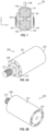
- an isolator 200 includes a case or a housing 201, a primary isolation chamber 202 in the housing 201, a backpressure chamber 203 in the housing 201, an elastomer dome 204 in the housing 201, and a backpressure membrane 205 in the housing 201 .
- the elastomer dome 204 and the backpressure membrane 205 are each dome-shaped members extending in opposite directions away from each other.
- the backpressure membrane 205 may have any other suitable shape (e.g., the backpressure membrane 205 may not be dome-shaped).
- the elastomer dome 204 and the backpressure membrane 205 are each made out of a resilient (e.g., elastic) material.
- the elastomer dome 204 and the backpressure membrane 205 are made out of any suitable type or kind of elastomer, such as silicone elastomers (e.g., NuSil TM 5840), ethylene propylene rubber (EPM), ethylene propylene diene rubber (EPDM), ethylene-vinyl acetate EVA), thermoplastic elastomers (TPE), natural polyisoprene, synthetic polyisoprene, Buna-N rubber (nitrile rubber), or combinations thereof.
- silicone elastomers e.g., NuSil TM 5840
- EPM ethylene propylene rubber
- EPDM ethylene propylene diene rubber
- TPE thermoplastic elastomers
- natural polyisoprene synthetic polyisoprene
- Buna-N rubber nitrile rubber
- the housing 201 includes a sidewall 206 (e.g., a cylindrical sidewall) extending between a first end 207 of the housing 201 and a second end 208 of the housing 201 opposite the first end 207 .
- the housing 201 is generally cylindrical, in one or more examples the housing 201 may have any other shape suitable for the environment in which the isolator 200 is intended to be utilized (e.g., a missile body or an oil well) to attenuate unwanted vibrations and/or shock.
- the housing 207 may have a prismatic shape.
- the backpressure chamber 203 is proximate to the first end 207 of the housing 201 and the primary isolation chamber 202 is proximate to the second end 208 of the housing 201 .
- the housing 201 includes a wall or partition 209 connected to the sidewall 206 .
- the partition 209 is positioned at an intermediate position between the first and second ends 207 , 208 of the housing 201 .
- the partition 209 separates the backpressure chamber 203 from the primary isolation chamber 202 .
- the partition 209 defines an opening 210 (e.g., a conduit) placing the primary isolation chamber 202 in fluid communication with the backpressure chamber 203 .
- the primary isolation chamber 202 is defined between the elastomer dome 204 , the partition 209, and a portion of the sidewall 206 proximate to the second end 208 of the housing 201.
- the backpressure chamber 203 is defined between the backpressure membrane 205 , the partition 209, and a portion of the sidewall 206 proximate to the first end 207 of the housing 201 .
- the isolator 200 includes a volume of liquid 211 in the primary isolation chamber 202 and the backpressure chamber 203 .
- the liquid 211 contained in the primary isolation chamber 202 and the backpressure chamber 203 is oil (e.g., a high viscosity oil such as high viscosity mineral oil).
- the opening 210 defines a fluid path (e.g., a fluid track) placing the primary isolation chamber 202 in fluid communication with the backpressure chamber 203 such that the liquid 211 can flow between the primary isolation chamber 202 and the backpressure chamber 203 .
- the first end 207 of the housing 201 is configured to be connected to a vibration source (e.g., a drill string).
- a vibration source e.g., a drill string
- an outer surface of the sidewall 206 at the first end 207 includes external threads and/or the first end 207 of the housing 201 may define a series of internally threaded openings configured to accommodate fasteners coupling the isolator 200 to the vibration source.
- the isolator 200 also includes a shaft 212 connected to the elastomer dome 204 .
- the shaft 212 is connected to the housing 201 by the elastomer dome 204 .
- the shaft 212 extends out through an opening 213 in the second end 208 of the housing 201 .
- the shaft 212 is configured to be connected to a payload, and the isolator 200 is configured to isolate the payload from unwanted vibrations and/or shocks transmitted to the housing 201 from the vibration source (i.e., the isolator 200 is configured to attenuate the transmission of unwanted vibrations from the vibration source to the payload connected to the shaft 212 ).
- the elastomer dome 204 In operation, movement of the housing 201 caused by vibrations and/or a shock transmitted to the housing 201 of the isolator 200 causes the elastomer dome 204 to deflect (e.g., deform), which reduces or limits transmission of the vibrations and/or the shock to the payload connected to the shaft 212 . That is, the deformable elastomer dome 204 effectively decouples the shaft 212 from the housing 201 to reduce the transmission of vibrations and/or shock to the payload connected to the shaft 212 .
- the elastomer dome 204 is configured to deflect both radially (e.g., the x-direction in FIG.
- the elastomer dome 204 is configured to provide multi-axis damping to attenuate the transmission of the vibrations and shocks to the isolated payload through the shaft 212 .
- the elastomer dome 204 is also configured to deflect rotationally about the axial direction (e.g., rotationally around the y-axis in FIG. 2C ) to provide vibration isolation in a rotational direction.
- the configuration of the elastomer dome 204 (e.g., the geometry of the elastomer dome 204 , including the shape, size, and thickness of the elastomer dome 204) and the material properties of the elastomer dome 204 (e.g., the material, hardness, and stiffness of the elastomer dome 204 ) may be selected depending on the magnitude of the vibrations and/or the shock input to the housing 201 from the vibration source and/or the desired degree of vibrational isolation provided to the payload connected to the shaft 212 .
- the elastomer dome 204 deflects axially in the direction of the first end 207 of the housing 201 (e.g., the -y-direction in FIG. 2C ).
- the deflection of the elastomer dome 204 in the direction of the first end 207 of the housing 201 reduces the volume of the primary isolation chamber 202 and thereby increases the pressure of the liquid 211 in the primary isolation chamber 202 .
- a volume of liquid 211 in the primary isolation chamber 202 corresponding to the volume of liquid 211 in the primary isolation chamber 202 that was displaced by the deflection or deformation of the elastomer dome 204 is forced through the opening 210 (e.g., the conduit) in the partition 209 into the backpressure chamber 203 .
- the elastomer dome 204 is configured to function as a piston to pump a volume of the liquid 211 in the primary isolation chamber 202 to the backpressure chamber 203 through the opening 210 in response to vibrations and/or a shock imparted to the housing 201 of the isolator 200 .
- the backpressure membrane 205 is configured to deflect and/or deform (e.g., in the direction of the first end 207 of the housing 201 ) in response to the influx of additional liquid 211 into the backpressure chamber 203 (e.g., the backpressure membrane 205 is configured to expand axially in the direction of the first end 207 of the housing 201, which increases the size of the backpressure chamber 203 to accommodate the influx of additional liquid 211 ).
- the deflection or deformation of the backpressure membrane 205 in the axial direction e.g., the negative y-direction in FIG.
- fluidic damping e.g., hydraulic damping
- the axial direction e.g., the y-axis in FIG. 2C
- the cross-sectional size of the opening 210 in the partition 209 (e.g., the conduit) is smaller than the cross-sectional size of the chambers 202, 203 such that the opening 210 restricts the flow of the fluid between the primary chamber 202 and the backpressure chamber 203 .
- This restriction of the liquid flow through the opening 210 is configured to provide fluidic damping to limit the transmission of vibrations and/or shock to the payload connected to the shaft 212 .
- the configuration (e.g., shape and size) of the opening 210 in the partition 209 may be selected depending on the magnitude of the vibrations and/or shock input to the housing 201 from the vibration source and/or the desired level of fluidic damping.
- the stiffness of the elastomer dome 204 is sufficiently soft to provide multi-axis damping, but stiff enough to pump a volume of the liquid 211 from the primary isolation chamber 202 to the backpressure chamber 203 through the opening 210 in the partition 209 .
- the deflection and/or deformation of the backpressure membrane 205 which is formed of a resilient (e.g., elastic) material, generates a restorative force in an axial direction (e.g., the positive y-direction in FIG. 2C ) opposite to the direction in which the backpressure membrane 205 was deflected and/or deformed.
- This restorative force is configured to force (e.g., pump) a volume of the liquid 211 in the backpressure chamber 203 back through the opening 210 in the partition 209 into the primary isolation chamber 202 .
- the restorative force supplied by the deflected backpressure membrane 205 is configured to force a volume of the liquid 211 into the primary isolation chamber 202 through the opening 210 until the pressure of the liquid 211 in the primary isolation chamber 202 substantially equals the pressure of the liquid 211 in the backpressure chamber 203 (e.g., the deflection and/or deformation of the backpressure membrane 205 is configured to change the pressure of the liquid 211 in the backpressure chamber 203 until a pressure equilibrium is reached between the liquid 211 in the primary isolation chamber 202 and the backpressure chamber 203 ).
- This cycle of pumping the liquid 211 between the primary isolation chamber 202 and the backpressure chamber 203 through the opening 210 in the partition 209 may continue as long as unwanted vibrations and/or shock are input to the housing 201 of the isolator 200 in order to provide fluidic damping to attenuate the transmission of the vibrations and/or the shocks to the isolated payload coupled to the shaft 212 .
- the example of the isolator 200 illustrated in FIGS. 2A-2C is configured to provide both multi-axis isolation (e.g., translational and rotational isolation) due to the elastomer dome 204 being coupled between the housing 201 and the shaft 212 , and fluidic damping (e.g., hydraulic damping) along the axial direction (e.g., the y-axis in FIG. 2C ) due to the pumping of the liquid 211 between the chambers 202, 203 through the opening 210 (e.g., the conduit) in the partition 209 .
- multi-axis isolation e.g., translational and rotational isolation
- fluidic damping e.g., hydraulic damping
- the isolator 200 includes a lateral bump stop contact 214 and an axial bump stop contact 215 .
- the bump stop contacts 214, 215 are coupled to the housing 201 proximate to the second end 208 of the housing 201 .
- the lateral bump stop contact 214 extends around an interior circumference of the opening 213 at the second end 208 of the housing 201 and extends radially inward from the sidewall 206 of the housing 201 (e.g., the annular bump contact 214 is an annular member extending radially inward from the sidewall 206 of the housing 201 ).
- the lateral bump stop contact 214 is spaced apart from and extends around a portion of the shaft 212 .
- the lateral bump stop contact 214 is configured to prevent lateral contact between the shaft 212 and the housing 201 (e.g., the sidewall 206 of the housing 201 ), which might otherwise occur if the housing 201 is subjected to large amplitude lateral vibrations and/or large amplitude lateral shocks.
- the axial bump stop contact 215 is an annular member extending around the second end 208 of the housing 201 .
- the axial bump stop contact 215 is configured to prevent axial contact between the shaft 212 and the second end 208 of the housing 201, which might otherwise occur if the housing 201 is subjected to large amplitude axial vibrations and/or axial shock. Accordingly, the lateral bump stop contact 214 and the axial bump stop contact 215 are configured to prevent lateral and axial contact, respectively, between the shaft 212 and the housing 201 which would transmit unwanted vibrations to the payload coupled to the shaft 212 . In the illustrated example, the lateral bump stop contact 214 and the axial bump stop contact 215 are integrally formed from a single, monolithic component extending around the second end 208 of the housing 201 .
- the lateral bump stop contact 214 and the axial bump stop contact 215 may be separate components.
- the configuration of the bump stop contacts 214, 215 (e.g., the size and thickness) and the material of the bump stop contacts 214, 215 (e.g., the hardness or durometer) may be selected depending on the amplitude of the vibration and/or shock events in the environment in which the isolator 200 will be utilized, and the desired damping provided by the bump stop contacts 214, 215 in the event of large amplitude axial and/or lateral vibrations and/or shocks.
- the bump stop contacts 214, 215 may be made out of an elastic material.
- the bump stop contacts 214, 215 are separate components, in one or more examples, the lateral bump stop contact 214 and the axial bump stop contact 215 may be integrally provided in a single component.
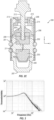
- FIG. 3 depicts the transmissibility of vibrations through an isolator 100, 200 according to one example of the present disclosure as a function of the vibration frequency.
- the isolator 100, 200 has a relatively low resonant frequency of approximately 40 Hz or less and a damping ratio of approximately 0.4.
- the isolator 100, 200 may have any other damping ratio suitable for the environment in which the isolator 100, 200 is intended to be utilized and/or the nature of the isolated payload, such as, for instance, a damping ratio greater than approximately 0.4 or less than approximately 0.4.
- An isolator according to one or more examples of the present disclosure was tested by subjecting the isolator to vibration levels up to approximately 18 g rms at frequencies from approximately 20 Hz to approximately 200 Hz.
- the tested isolator achieved a travel of approximately +/- 0.25 inches in the axial and radial directions, which demonstrates that the isolator provided adequate damping of unwanted vibrations under these conditions.
- FIG. 4 depicts two isolators according to one or more examples of the present disclosure (e.g., the isolator 100 illustrated in FIG. 1 or the isolator 200 illustrated in FIGS. 2A-2C ) utilized in a petroleum drill well 301 to isolate a sensor chassis 302 containing one or more sensors from unwanted vibrations and/or shocks.
- the isolators 100, 200 are connected to opposite ends of the sensor chassis 302 .
- the isolators 100, 200 are configured to attenuate unwanted vibrations from a pressure casing 303 rigidly connected to a vibrating drill string 304 of the petroleum drill well 301 .
- the isolators 100, 200 are configured to allow the sensor chassis 302 to translate and/or rotate with the pressure casing 303 with a prescribed amount of stiffness and damping such that desired degrees of freedom of motion of the sensor chassis 302 are isolated from the vibration of the drill string 304 and the pressure casing 303 rigidly connected thereto.
- the isolators 100, 200 of the present disclosure may be utilized to isolate any other component or components from unwanted vibrations (e.g., the isolators 100, 200 may be utilized to isolate sensitive electronic payloads, such as sensor suites in missile bodies).
- the term "substantially,” “about,” and similar terms are used as terms of approximation and not as terms of degree, and are intended to account for the inherent deviations in measured or calculated values that would be recognized by those of ordinary skill in the art.
- the tasks described above may be performed in the order described or in any other suitable sequence. Additionally, the methods described above are not limited to the tasks described. Instead, for each example, one or more of the tasks described above may be absent and/or additional tasks may be performed.
- when a component is referred to as being “on” another component it can be directly on the other component or components may also be present therebetween.
- a component is component is referred to as being “coupled” to another component, it can be directly attached to the other component or intervening components may be present therebetween.
Landscapes
- Engineering & Computer Science (AREA)
- General Engineering & Computer Science (AREA)
- Mechanical Engineering (AREA)
- Physics & Mathematics (AREA)
- Acoustics & Sound (AREA)
- Aviation & Aerospace Engineering (AREA)
- Life Sciences & Earth Sciences (AREA)
- Geology (AREA)
- Mining & Mineral Resources (AREA)
- Environmental & Geological Engineering (AREA)
- Fluid Mechanics (AREA)
- General Life Sciences & Earth Sciences (AREA)
- Geochemistry & Mineralogy (AREA)
- Combined Devices Of Dampers And Springs (AREA)
Claims (10)
- Isolateur (100, 200) configuré pour isoler une charge utile de vibrations et de chocs indésirables, l'isolateur comprenant :un boîtier (201) présentant une première extrémité (207) et une deuxième extrémité (208) opposée à la première extrémité ;une chambre principale (202) définie dans le boîtier ;une chambre de contre-pression (203) définie dans le boîtier ;un conduit (103, 210) plaçant la chambre principale en communication fluidique avec la chambre de contre-pression ;une membrane de contre-pression (106, 205) dans le boîtier proche de la première extrémité,dans lequel la membrane de contre-pression (106, 205) comprend un matériau élastique, et dans lequel une déformation de la membrane de contre-pression (106, 205) dans une direction axiale a pour objet de générer une force restauratrice dans la membrane de contre-pression (106, 205) dans une direction axiale opposée à la direction dans laquelle la membrane de contre-pression (106, 205) a été déviée et/ou déformée ;un dôme en élastomère (105, 204) dans le boîtier proche de la deuxième extrémité, dans lequel la chambre principale et la chambre de contre-pression sont placées entre la membrane de contre-pression et le dôme en élastomère, et le dôme en élastomère est configuré pour se dévier à la fois axialement et radialement pour fournir une isolation vibratoire dans toutes les directions de translation ;un arbre (108, 212) connecté au dôme en élastomère, l'arbre configuré pour être connecté à la charge utile,caractérisé en ce que l'isolateur (100, 200) comprend en outreune butée latérale (214) connectée à la deuxième extrémité du boîtier, la butée latérale s'étendant vers l'intérieur du boîtier vers l'arbre, étant éloignée par espacement et s'étendant autour d'une partie de l'arbre (108, 212).
- L'isolateur de la revendication 1, dans lequel, lorsque des vibrations ou des chocs sont transmis au boîtier :le dôme en élastomère se dévie pour atténuer les vibrations ou les chocs atteignant la charge utile par le biais de l'arbre,la déviation du dôme en élastomère force un volume d'un liquide présent dans la chambre principale via le conduit dans la chambre de contre-pression, etun flux entrant du volume du liquide dans la chambre de contre-pression dévie la membrane de contre-pression, et la déviation de la membrane de contre-pression génère une force restauratrice configurée pour forcer un volume du liquide présent dans la chambre de contre-pression dans la chambre principale via le conduit.
- L'isolateur de la revendication 1 ou la revendication 2, dans lequel le boîtier comprend une cloison séparant la chambre principale de la chambre de contre-pression, et dans lequel le conduit est une ouverture définie dans la cloison.
- L'isolateur de l'une quelconque des revendications précédentes, comprenant en outre un liquide dans la chambre principale et dans la chambre de contre-pression.
- L'isolateur de la revendication 4, dans lequel le liquide est une huile.
- L'isolateur de l'une quelconque des revendications précédentes, dans lequel le matériau élastique est un élastomère de silicone.
- L'isolateur de l'une quelconque des revendications précédentes, comprenant en outre une butée axiale connectée au boîtier.
- Procédé d'isolation d'une charge utile de vibrations et de chocs indésirables utilisant l'isolateur de la revendication 1, le procédé comprenant :une déformation du dôme en élastomère disposé entre une source de vibrations et la charge utile pour fournir un amortissement sur des axes multiples ; etun pompage d'un volume de liquide de la chambre principale dans la chambre de contre-pression via le conduit avec le dôme en élastomère pour fournir un amortissement fluidique.
- Le procédé de la revendication 8, comprenant en outre un pompage d'un volume du liquide de la chambre de contre-pression dans la chambre principale avec la membrane de contre-pression.
- Le procédé de la revendication 8 ou la revendication 9, dans lequel le liquide est une huile minérale.
Applications Claiming Priority (2)
| Application Number | Priority Date | Filing Date | Title |
|---|---|---|---|
| US201762524941P | 2017-06-26 | 2017-06-26 | |
| PCT/US2018/028299 WO2019005269A1 (fr) | 2017-06-26 | 2018-04-19 | Isolateur de vibrations de fluide et d'élastomère |
Publications (3)
| Publication Number | Publication Date |
|---|---|
| EP3645908A1 EP3645908A1 (fr) | 2020-05-06 |
| EP3645908A4 EP3645908A4 (fr) | 2021-03-24 |
| EP3645908B1 true EP3645908B1 (fr) | 2025-02-26 |
Family
ID=64692106
Family Applications (1)
| Application Number | Title | Priority Date | Filing Date |
|---|---|---|---|
| EP18822993.4A Active EP3645908B1 (fr) | 2017-06-26 | 2018-04-19 | Isolateur de vibrations de fluide et d'élastomère |
Country Status (4)
| Country | Link |
|---|---|
| US (1) | US10788095B2 (fr) |
| EP (1) | EP3645908B1 (fr) |
| CN (1) | CN110770467B (fr) |
| WO (1) | WO2019005269A1 (fr) |
Families Citing this family (4)
| Publication number | Priority date | Publication date | Assignee | Title |
|---|---|---|---|---|
| EP3721055B1 (fr) | 2017-12-04 | 2023-04-26 | HRL Laboratories, LLC | Calcul de trajectoire continue pour forage directionnel |
| CN111852369B (zh) * | 2020-08-04 | 2021-08-06 | 中国地质大学(北京) | 一种新型多煤层敲击振动增产系统 |
| CN112356924B (zh) * | 2020-10-26 | 2022-08-23 | 东风越野车有限公司 | 一种复合液压阻尼装置和车身悬置 |
| WO2023118619A1 (fr) | 2021-12-23 | 2023-06-29 | Airbus Defence And Space, S.A. | Dispositif d'atténuation de chocs |
Citations (1)
| Publication number | Priority date | Publication date | Assignee | Title |
|---|---|---|---|---|
| US4787610A (en) * | 1984-09-05 | 1988-11-29 | Bridgestone Corporation | Vibration isolating devices |
Family Cites Families (38)
| Publication number | Priority date | Publication date | Assignee | Title |
|---|---|---|---|---|
| US3137466A (en) | 1962-05-23 | 1964-06-16 | Gen Motors Corp | Engine mount |
| FR2533506B1 (fr) * | 1982-09-28 | 1987-06-26 | Ouest Cie | Support elastique antivibratoire |
| DE3244296A1 (de) * | 1982-11-30 | 1984-05-30 | Metzeler Kautschuk GmbH, 8000 München | Zweikammer-motorlager mit hydraulischer daempfung |
| US4583723A (en) * | 1983-06-10 | 1986-04-22 | Toyoda Gosei Co., Ltd. | Elastically damping device for suspension of engine |
| JP2693434B2 (ja) * | 1986-12-29 | 1997-12-24 | 株式会社ブリヂストン | サスペンション用減衰力発生装置およびそれの作動制御装置 |
| US4779852A (en) | 1987-08-17 | 1988-10-25 | Teleco Oilfield Services Inc. | Vibration isolator and shock absorber device with conical disc springs |
| US4895353A (en) | 1988-06-28 | 1990-01-23 | The Pullman Company | Fluid filled elastomeric damping device |
| US4962915A (en) | 1989-07-18 | 1990-10-16 | Lord Corporation | Three-axis fluid-filled mount |
| JPH03234938A (ja) * | 1989-08-25 | 1991-10-18 | Bridgestone Corp | 振動減衰装置 |
| JPH04219536A (ja) * | 1990-09-25 | 1992-08-10 | Bridgestone Corp | 振動減衰装置 |
| JPH04302728A (ja) * | 1991-03-29 | 1992-10-26 | Toyoda Gosei Co Ltd | 液封入防振装置 |
| FR2675558A1 (fr) * | 1991-04-22 | 1992-10-23 | Hutchinson | Barre elastique de liaison a systeme de controle actif des vibrations. |
| US5180145A (en) * | 1991-05-30 | 1993-01-19 | Bridgestone Corporation | Vibration damping device |
| JPH07133840A (ja) * | 1993-11-11 | 1995-05-23 | Bridgestone Corp | 電気粘性流体を用いた装置 |
| DE19508980C2 (de) * | 1995-03-13 | 2000-06-15 | Daimler Chrysler Ag | Luftfederbein |
| US5516084A (en) | 1995-04-14 | 1996-05-14 | General Motors Corporation | Hydraulic engine mount with diaphragm decoupler |
| US5878851A (en) * | 1996-07-02 | 1999-03-09 | Lord Corporation | Controllable vibration apparatus |
| JPH10252829A (ja) | 1997-03-10 | 1998-09-22 | Nippon Oil Co Ltd | セミアクティブ制振ダンパ |
| JPH10331907A (ja) | 1997-06-04 | 1998-12-15 | Bridgestone Corp | 防振装置 |
| US6386134B1 (en) | 2000-03-13 | 2002-05-14 | Lockheed Martin Corporation | Elastomeric six degree of freedom isolator |
| JP2001343045A (ja) * | 2000-03-30 | 2001-12-14 | Tokai Rubber Ind Ltd | 空気圧加振式の流体封入式防振装置 |
| US6565061B1 (en) | 2000-09-28 | 2003-05-20 | Honeywell International Inc. | Radial snubber for vibration isolator |
| US20030178267A1 (en) * | 2002-03-20 | 2003-09-25 | Doyle James D. | Fluid separator for a shock absorber |
| US6758466B2 (en) * | 2002-11-06 | 2004-07-06 | Lord Corporation | Fluid-elastomeric damper assembly including internal pumping mechanism |
| DE10307680A1 (de) | 2003-02-21 | 2004-09-30 | Carl Freudenberg Kg | Hydrolager |
| JP2005009626A (ja) | 2003-06-20 | 2005-01-13 | Toyo Tire & Rubber Co Ltd | 防振装置 |
| US7219752B2 (en) * | 2003-11-07 | 2007-05-22 | Aps Technologies, Inc. | System and method for damping vibration in a drill string |
| JP4277316B2 (ja) * | 2005-03-30 | 2009-06-10 | 東海ゴム工業株式会社 | 防振装置 |
| JP4861880B2 (ja) * | 2007-03-30 | 2012-01-25 | 東海ゴム工業株式会社 | 流体封入式防振装置及び該流体封入式防振装置の製造方法 |
| JP5210558B2 (ja) * | 2007-07-12 | 2013-06-12 | 株式会社ブリヂストン | 防振装置 |
| US8016274B2 (en) * | 2007-09-26 | 2011-09-13 | Paulstra Crc | Antivibration device, and vehicle comprising same |
| JP5307486B2 (ja) * | 2008-09-16 | 2013-10-02 | 株式会社ブリヂストン | 空気ばね |
| CN102414474B (zh) * | 2009-04-28 | 2013-11-20 | 株式会社普利司通 | 隔振装置 |
| US8152145B2 (en) * | 2009-04-29 | 2012-04-10 | Honeywell International Inc. | Isoelastic magneto-rheological elastomer isolator |
| JP2012202512A (ja) * | 2011-03-28 | 2012-10-22 | Tokai Rubber Ind Ltd | 多方向防振型の流体封入式防振装置 |
| CN102588502B (zh) * | 2011-12-30 | 2013-12-04 | 宁波泛亚汽车部件有限公司 | 一种发动机液压悬置 |
| US9187997B2 (en) | 2012-02-13 | 2015-11-17 | General Downhole Technologies, Ltd. | System, method and apparatus for reducing shock and vibration in down hole tools |
| JP5907783B2 (ja) * | 2012-04-06 | 2016-04-26 | 住友理工株式会社 | 流体封入式防振装置 |
-
2018
- 2018-04-19 CN CN201880041063.8A patent/CN110770467B/zh active Active
- 2018-04-19 EP EP18822993.4A patent/EP3645908B1/fr active Active
- 2018-04-19 US US15/957,202 patent/US10788095B2/en active Active
- 2018-04-19 WO PCT/US2018/028299 patent/WO2019005269A1/fr not_active Ceased
Patent Citations (1)
| Publication number | Priority date | Publication date | Assignee | Title |
|---|---|---|---|---|
| US4787610A (en) * | 1984-09-05 | 1988-11-29 | Bridgestone Corporation | Vibration isolating devices |
Also Published As
| Publication number | Publication date |
|---|---|
| EP3645908A4 (fr) | 2021-03-24 |
| CN110770467A (zh) | 2020-02-07 |
| WO2019005269A1 (fr) | 2019-01-03 |
| EP3645908A1 (fr) | 2020-05-06 |
| US10788095B2 (en) | 2020-09-29 |
| US20180372180A1 (en) | 2018-12-27 |
| CN110770467B (zh) | 2021-09-17 |
Similar Documents
| Publication | Publication Date | Title |
|---|---|---|
| US10788095B2 (en) | Fluid and elastomer vibration isolator | |
| JP4714226B2 (ja) | 外部から加圧されるシールベローズを使用する改善された隔離器 | |
| JP4919783B2 (ja) | 液封防振装置 | |
| US6138980A (en) | Pilot mounting | |
| US10393213B2 (en) | Vibration-damping device | |
| KR20090032018A (ko) | 진동방지장치 및 그를 포함하는 차량 | |
| US6598865B1 (en) | Fluid-filled vibration damping device | |
| US7007934B2 (en) | Fluid-filled vibration damping device | |
| WO2018135312A1 (fr) | Dispositif d'amortissement de vibrations | |
| KR101329478B1 (ko) | 액체봉입식마운트 및 그 조립방법 | |
| CN116324211B (zh) | 隔振装置 | |
| WO2010106192A1 (fr) | Système de montage pour pistolet à gaz | |
| EP1571369B1 (fr) | Arrangement fluidique et élastomérique avec compensateur de volume discret et seconde unité d'adaptation | |
| US7128311B2 (en) | Active vibration damping actuator and active damping apparatus using the same | |
| JP4023462B2 (ja) | 能動型流体封入式防振装置 | |
| JP4075062B2 (ja) | 能動型流体封入式防振装置 | |
| JP4238128B2 (ja) | 防振装置 | |
| EP1137889B1 (fr) | Cartouche d'amortissement hydraulique pour tendeur de courroie | |
| JP4079072B2 (ja) | 能動型流体封入式防振装置 | |
| JP6122376B2 (ja) | 防振装置 | |
| US11187047B1 (en) | Multi-degree of freedom vibration isolator | |
| JP2009281536A (ja) | 防振装置 | |
| JP6814615B2 (ja) | 流体封入式防振装置 | |
| JPH09280299A (ja) | 防振装置 | |
| JP2007032745A (ja) | 流体封入式防振装置 |
Legal Events
| Date | Code | Title | Description |
|---|---|---|---|
| STAA | Information on the status of an ep patent application or granted ep patent |
Free format text: STATUS: THE INTERNATIONAL PUBLICATION HAS BEEN MADE |
|
| PUAI | Public reference made under article 153(3) epc to a published international application that has entered the european phase |
Free format text: ORIGINAL CODE: 0009012 |
|
| STAA | Information on the status of an ep patent application or granted ep patent |
Free format text: STATUS: REQUEST FOR EXAMINATION WAS MADE |
|
| 17P | Request for examination filed |
Effective date: 20191203 |
|
| AK | Designated contracting states |
Kind code of ref document: A1 Designated state(s): AL AT BE BG CH CY CZ DE DK EE ES FI FR GB GR HR HU IE IS IT LI LT LU LV MC MK MT NL NO PL PT RO RS SE SI SK SM TR |
|
| AX | Request for extension of the european patent |
Extension state: BA ME |
|
| DAV | Request for validation of the european patent (deleted) | ||
| DAX | Request for extension of the european patent (deleted) | ||
| A4 | Supplementary search report drawn up and despatched |
Effective date: 20210222 |
|
| RIC1 | Information provided on ipc code assigned before grant |
Ipc: F16F 13/10 20060101AFI20210216BHEP |
|
| STAA | Information on the status of an ep patent application or granted ep patent |
Free format text: STATUS: EXAMINATION IS IN PROGRESS |
|
| 17Q | First examination report despatched |
Effective date: 20240214 |
|
| GRAP | Despatch of communication of intention to grant a patent |
Free format text: ORIGINAL CODE: EPIDOSNIGR1 |
|
| STAA | Information on the status of an ep patent application or granted ep patent |
Free format text: STATUS: GRANT OF PATENT IS INTENDED |
|
| INTG | Intention to grant announced |
Effective date: 20240930 |
|
| P01 | Opt-out of the competence of the unified patent court (upc) registered |
Free format text: CASE NUMBER: APP_65078/2024 Effective date: 20241210 |
|
| GRAS | Grant fee paid |
Free format text: ORIGINAL CODE: EPIDOSNIGR3 |
|
| GRAA | (expected) grant |
Free format text: ORIGINAL CODE: 0009210 |
|
| STAA | Information on the status of an ep patent application or granted ep patent |
Free format text: STATUS: THE PATENT HAS BEEN GRANTED |
|
| AK | Designated contracting states |
Kind code of ref document: B1 Designated state(s): AL AT BE BG CH CY CZ DE DK EE ES FI FR GB GR HR HU IE IS IT LI LT LU LV MC MK MT NL NO PL PT RO RS SE SI SK SM TR |
|
| REG | Reference to a national code |
Ref country code: GB Ref legal event code: FG4D |
|
| REG | Reference to a national code |
Ref country code: CH Ref legal event code: EP |
|
| REG | Reference to a national code |
Ref country code: DE Ref legal event code: R096 Ref document number: 602018079647 Country of ref document: DE |
|
| REG | Reference to a national code |
Ref country code: IE Ref legal event code: FG4D |
|
| REG | Reference to a national code |
Ref country code: NL Ref legal event code: MP Effective date: 20250226 |
|
| PG25 | Lapsed in a contracting state [announced via postgrant information from national office to epo] |
Ref country code: RS Free format text: LAPSE BECAUSE OF FAILURE TO SUBMIT A TRANSLATION OF THE DESCRIPTION OR TO PAY THE FEE WITHIN THE PRESCRIBED TIME-LIMIT Effective date: 20250526 |
|
| PG25 | Lapsed in a contracting state [announced via postgrant information from national office to epo] |
Ref country code: FI Free format text: LAPSE BECAUSE OF FAILURE TO SUBMIT A TRANSLATION OF THE DESCRIPTION OR TO PAY THE FEE WITHIN THE PRESCRIBED TIME-LIMIT Effective date: 20250226 |
|
| PG25 | Lapsed in a contracting state [announced via postgrant information from national office to epo] |
Ref country code: PL Free format text: LAPSE BECAUSE OF FAILURE TO SUBMIT A TRANSLATION OF THE DESCRIPTION OR TO PAY THE FEE WITHIN THE PRESCRIBED TIME-LIMIT Effective date: 20250226 |
|
| PGFP | Annual fee paid to national office [announced via postgrant information from national office to epo] |
Ref country code: DE Payment date: 20250429 Year of fee payment: 8 |
|
| PG25 | Lapsed in a contracting state [announced via postgrant information from national office to epo] |
Ref country code: ES Free format text: LAPSE BECAUSE OF FAILURE TO SUBMIT A TRANSLATION OF THE DESCRIPTION OR TO PAY THE FEE WITHIN THE PRESCRIBED TIME-LIMIT Effective date: 20250226 |
|
| REG | Reference to a national code |
Ref country code: LT Ref legal event code: MG9D |
|
| PG25 | Lapsed in a contracting state [announced via postgrant information from national office to epo] |
Ref country code: NO Free format text: LAPSE BECAUSE OF FAILURE TO SUBMIT A TRANSLATION OF THE DESCRIPTION OR TO PAY THE FEE WITHIN THE PRESCRIBED TIME-LIMIT Effective date: 20250526 Ref country code: IS Free format text: LAPSE BECAUSE OF FAILURE TO SUBMIT A TRANSLATION OF THE DESCRIPTION OR TO PAY THE FEE WITHIN THE PRESCRIBED TIME-LIMIT Effective date: 20250626 |
|
| PG25 | Lapsed in a contracting state [announced via postgrant information from national office to epo] |
Ref country code: NL Free format text: LAPSE BECAUSE OF FAILURE TO SUBMIT A TRANSLATION OF THE DESCRIPTION OR TO PAY THE FEE WITHIN THE PRESCRIBED TIME-LIMIT Effective date: 20250226 |
|
| PG25 | Lapsed in a contracting state [announced via postgrant information from national office to epo] |
Ref country code: HR Free format text: LAPSE BECAUSE OF FAILURE TO SUBMIT A TRANSLATION OF THE DESCRIPTION OR TO PAY THE FEE WITHIN THE PRESCRIBED TIME-LIMIT Effective date: 20250226 |
|
| PG25 | Lapsed in a contracting state [announced via postgrant information from national office to epo] |
Ref country code: LV Free format text: LAPSE BECAUSE OF FAILURE TO SUBMIT A TRANSLATION OF THE DESCRIPTION OR TO PAY THE FEE WITHIN THE PRESCRIBED TIME-LIMIT Effective date: 20250226 Ref country code: PT Free format text: LAPSE BECAUSE OF FAILURE TO SUBMIT A TRANSLATION OF THE DESCRIPTION OR TO PAY THE FEE WITHIN THE PRESCRIBED TIME-LIMIT Effective date: 20250626 |
|
| PG25 | Lapsed in a contracting state [announced via postgrant information from national office to epo] |
Ref country code: BG Free format text: LAPSE BECAUSE OF FAILURE TO SUBMIT A TRANSLATION OF THE DESCRIPTION OR TO PAY THE FEE WITHIN THE PRESCRIBED TIME-LIMIT Effective date: 20250226 Ref country code: GR Free format text: LAPSE BECAUSE OF FAILURE TO SUBMIT A TRANSLATION OF THE DESCRIPTION OR TO PAY THE FEE WITHIN THE PRESCRIBED TIME-LIMIT Effective date: 20250527 |
|
| REG | Reference to a national code |
Ref country code: AT Ref legal event code: MK05 Ref document number: 1770896 Country of ref document: AT Kind code of ref document: T Effective date: 20250226 |
|
| PG25 | Lapsed in a contracting state [announced via postgrant information from national office to epo] |
Ref country code: SE Free format text: LAPSE BECAUSE OF FAILURE TO SUBMIT A TRANSLATION OF THE DESCRIPTION OR TO PAY THE FEE WITHIN THE PRESCRIBED TIME-LIMIT Effective date: 20250226 |
|
| PG25 | Lapsed in a contracting state [announced via postgrant information from national office to epo] |
Ref country code: SM Free format text: LAPSE BECAUSE OF FAILURE TO SUBMIT A TRANSLATION OF THE DESCRIPTION OR TO PAY THE FEE WITHIN THE PRESCRIBED TIME-LIMIT Effective date: 20250226 |
|
| PG25 | Lapsed in a contracting state [announced via postgrant information from national office to epo] |
Ref country code: DK Free format text: LAPSE BECAUSE OF FAILURE TO SUBMIT A TRANSLATION OF THE DESCRIPTION OR TO PAY THE FEE WITHIN THE PRESCRIBED TIME-LIMIT Effective date: 20250226 |
|
| PG25 | Lapsed in a contracting state [announced via postgrant information from national office to epo] |
Ref country code: IT Free format text: LAPSE BECAUSE OF FAILURE TO SUBMIT A TRANSLATION OF THE DESCRIPTION OR TO PAY THE FEE WITHIN THE PRESCRIBED TIME-LIMIT Effective date: 20250226 |
|
| PG25 | Lapsed in a contracting state [announced via postgrant information from national office to epo] |
Ref country code: AT Free format text: LAPSE BECAUSE OF FAILURE TO SUBMIT A TRANSLATION OF THE DESCRIPTION OR TO PAY THE FEE WITHIN THE PRESCRIBED TIME-LIMIT Effective date: 20250226 |
|
| PG25 | Lapsed in a contracting state [announced via postgrant information from national office to epo] |
Ref country code: EE Free format text: LAPSE BECAUSE OF FAILURE TO SUBMIT A TRANSLATION OF THE DESCRIPTION OR TO PAY THE FEE WITHIN THE PRESCRIBED TIME-LIMIT Effective date: 20250226 Ref country code: CZ Free format text: LAPSE BECAUSE OF FAILURE TO SUBMIT A TRANSLATION OF THE DESCRIPTION OR TO PAY THE FEE WITHIN THE PRESCRIBED TIME-LIMIT Effective date: 20250226 |
|
| PG25 | Lapsed in a contracting state [announced via postgrant information from national office to epo] |
Ref country code: RO Free format text: LAPSE BECAUSE OF FAILURE TO SUBMIT A TRANSLATION OF THE DESCRIPTION OR TO PAY THE FEE WITHIN THE PRESCRIBED TIME-LIMIT Effective date: 20250226 |
|
| PG25 | Lapsed in a contracting state [announced via postgrant information from national office to epo] |
Ref country code: SK Free format text: LAPSE BECAUSE OF FAILURE TO SUBMIT A TRANSLATION OF THE DESCRIPTION OR TO PAY THE FEE WITHIN THE PRESCRIBED TIME-LIMIT Effective date: 20250226 |
|
| REG | Reference to a national code |
Ref country code: CH Ref legal event code: H13 Free format text: ST27 STATUS EVENT CODE: U-0-0-H10-H13 (AS PROVIDED BY THE NATIONAL OFFICE) Effective date: 20251125 |
|
| REG | Reference to a national code |
Ref country code: DE Ref legal event code: R097 Ref document number: 602018079647 Country of ref document: DE |
|
| PG25 | Lapsed in a contracting state [announced via postgrant information from national office to epo] |
Ref country code: LU Free format text: LAPSE BECAUSE OF NON-PAYMENT OF DUE FEES Effective date: 20250419 |
|
| PG25 | Lapsed in a contracting state [announced via postgrant information from national office to epo] |
Ref country code: MC Free format text: LAPSE BECAUSE OF FAILURE TO SUBMIT A TRANSLATION OF THE DESCRIPTION OR TO PAY THE FEE WITHIN THE PRESCRIBED TIME-LIMIT Effective date: 20250226 |
|
| REG | Reference to a national code |
Ref country code: BE Ref legal event code: MM Effective date: 20250430 |
|
| PLBE | No opposition filed within time limit |
Free format text: ORIGINAL CODE: 0009261 |
|
| STAA | Information on the status of an ep patent application or granted ep patent |
Free format text: STATUS: NO OPPOSITION FILED WITHIN TIME LIMIT |
|
| PG25 | Lapsed in a contracting state [announced via postgrant information from national office to epo] |
Ref country code: FR Free format text: LAPSE BECAUSE OF NON-PAYMENT OF DUE FEES Effective date: 20250426 |
|
| PG25 | Lapsed in a contracting state [announced via postgrant information from national office to epo] |
Ref country code: BE Free format text: LAPSE BECAUSE OF NON-PAYMENT OF DUE FEES Effective date: 20250430 |
|
| PG25 | Lapsed in a contracting state [announced via postgrant information from national office to epo] |
Ref country code: CH Free format text: LAPSE BECAUSE OF NON-PAYMENT OF DUE FEES Effective date: 20250430 |
|
| GBPC | Gb: european patent ceased through non-payment of renewal fee |
Effective date: 20250526 |
|
| 26N | No opposition filed |
Effective date: 20251127 |
|
| PG25 | Lapsed in a contracting state [announced via postgrant information from national office to epo] |
Ref country code: GB Free format text: LAPSE BECAUSE OF NON-PAYMENT OF DUE FEES Effective date: 20250526 |
|
| PG25 | Lapsed in a contracting state [announced via postgrant information from national office to epo] |
Ref country code: IE Free format text: LAPSE BECAUSE OF NON-PAYMENT OF DUE FEES Effective date: 20250419 |