EP3645954B1 - Heat transfer elements for rotary heat exchangers - Google Patents
Heat transfer elements for rotary heat exchangers Download PDFInfo
- Publication number
- EP3645954B1 EP3645954B1 EP18746286.6A EP18746286A EP3645954B1 EP 3645954 B1 EP3645954 B1 EP 3645954B1 EP 18746286 A EP18746286 A EP 18746286A EP 3645954 B1 EP3645954 B1 EP 3645954B1
- Authority
- EP
- European Patent Office
- Prior art keywords
- heat transfer
- transfer element
- relative
- angle
- plate
- Prior art date
- Legal status (The legal status is an assumption and is not a legal conclusion. Google has not performed a legal analysis and makes no representation as to the accuracy of the status listed.)
- Active
Links
Images




Classifications
-
- F—MECHANICAL ENGINEERING; LIGHTING; HEATING; WEAPONS; BLASTING
- F28—HEAT EXCHANGE IN GENERAL
- F28D—HEAT-EXCHANGE APPARATUS, NOT PROVIDED FOR IN ANOTHER SUBCLASS, IN WHICH THE HEAT-EXCHANGE MEDIA DO NOT COME INTO DIRECT CONTACT
- F28D19/00—Regenerative heat-exchange apparatus in which the intermediate heat-transfer medium or body is moved successively into contact with each heat-exchange medium
- F28D19/04—Regenerative heat-exchange apparatus in which the intermediate heat-transfer medium or body is moved successively into contact with each heat-exchange medium using rigid bodies, e.g. mounted on a movable carrier
- F28D19/041—Regenerative heat-exchange apparatus in which the intermediate heat-transfer medium or body is moved successively into contact with each heat-exchange medium using rigid bodies, e.g. mounted on a movable carrier with axial flow through the intermediate heat-transfer medium
- F28D19/042—Rotors; Assemblies of heat absorbing masses
- F28D19/044—Rotors; Assemblies of heat absorbing masses shaped in sector form, e.g. with baskets
-
- F—MECHANICAL ENGINEERING; LIGHTING; HEATING; WEAPONS; BLASTING
- F28—HEAT EXCHANGE IN GENERAL
- F28F—DETAILS OF HEAT-EXCHANGE AND HEAT-TRANSFER APPARATUS, OF GENERAL APPLICATION
- F28F3/00—Plate-like or laminated elements; Assemblies of plate-like or laminated elements
- F28F3/02—Elements or assemblies thereof with means for increasing heat-transfer area, e.g. with fins, with recesses, with corrugations
- F28F3/025—Elements or assemblies thereof with means for increasing heat-transfer area, e.g. with fins, with recesses, with corrugations the means being corrugated, plate-like elements
-
- F—MECHANICAL ENGINEERING; LIGHTING; HEATING; WEAPONS; BLASTING
- F28—HEAT EXCHANGE IN GENERAL
- F28F—DETAILS OF HEAT-EXCHANGE AND HEAT-TRANSFER APPARATUS, OF GENERAL APPLICATION
- F28F3/00—Plate-like or laminated elements; Assemblies of plate-like or laminated elements
- F28F3/02—Elements or assemblies thereof with means for increasing heat-transfer area, e.g. with fins, with recesses, with corrugations
- F28F3/04—Elements or assemblies thereof with means for increasing heat-transfer area, e.g. with fins, with recesses, with corrugations the means being integral with the element
- F28F3/042—Elements or assemblies thereof with means for increasing heat-transfer area, e.g. with fins, with recesses, with corrugations the means being integral with the element in the form of local deformations of the element
- F28F3/044—Elements or assemblies thereof with means for increasing heat-transfer area, e.g. with fins, with recesses, with corrugations the means being integral with the element in the form of local deformations of the element the deformations being pontual, e.g. dimples
-
- F—MECHANICAL ENGINEERING; LIGHTING; HEATING; WEAPONS; BLASTING
- F28—HEAT EXCHANGE IN GENERAL
- F28F—DETAILS OF HEAT-EXCHANGE AND HEAT-TRANSFER APPARATUS, OF GENERAL APPLICATION
- F28F3/00—Plate-like or laminated elements; Assemblies of plate-like or laminated elements
- F28F3/02—Elements or assemblies thereof with means for increasing heat-transfer area, e.g. with fins, with recesses, with corrugations
- F28F3/04—Elements or assemblies thereof with means for increasing heat-transfer area, e.g. with fins, with recesses, with corrugations the means being integral with the element
- F28F3/042—Elements or assemblies thereof with means for increasing heat-transfer area, e.g. with fins, with recesses, with corrugations the means being integral with the element in the form of local deformations of the element
- F28F3/046—Elements or assemblies thereof with means for increasing heat-transfer area, e.g. with fins, with recesses, with corrugations the means being integral with the element in the form of local deformations of the element the deformations being linear, e.g. corrugations
-
- F—MECHANICAL ENGINEERING; LIGHTING; HEATING; WEAPONS; BLASTING
- F28—HEAT EXCHANGE IN GENERAL
- F28F—DETAILS OF HEAT-EXCHANGE AND HEAT-TRANSFER APPARATUS, OF GENERAL APPLICATION
- F28F5/00—Elements specially adapted for movement
-
- F—MECHANICAL ENGINEERING; LIGHTING; HEATING; WEAPONS; BLASTING
- F01—MACHINES OR ENGINES IN GENERAL; ENGINE PLANTS IN GENERAL; STEAM ENGINES
- F01K—STEAM ENGINE PLANTS; STEAM ACCUMULATORS; ENGINE PLANTS NOT OTHERWISE PROVIDED FOR; ENGINES USING SPECIAL WORKING FLUIDS OR CYCLES
- F01K11/00—Plants characterised by the engines being structurally combined with boilers or condensers
- F01K11/02—Plants characterised by the engines being structurally combined with boilers or condensers the engines being turbines
Definitions
- Present invention embodiments are related to heat transfer elements for rotary heat exchangers.
- Natural gas is an attractive alternative to coal in terms of thermal efficiency and reduced emissions, but until recently was more expensive and not as readily available as coal.
- Recent developments in hydraulic fracturing have increased the availability and reduced the cost of natural gas.
- many coal-fired boilers are now being converted to natural gas firing.
- components such as rotary heat exchangers originally designed for coal-fired boilers do not take full advantage of the cleaner, lower emission gas flow and higher thermal potential associated with natural or "fracked" gas.
- US4930569A discloses a heat transfer element assembly comprised of a plurality of first and second profiled heat transfer plates which incorporate a series of first and second single-lobed outwardly protruding notches which extend obliquely relative to the general direction of fluid flow through the assembled plates.
- a heat transfer element for a rotary heat exchanger having a flow direction.
- the heat transfer element comprises a plate having a plurality of elongate notches formed therein at spaced intervals.
- the elongate notches are each oriented at a first angle relative to the flow direction and have a first height relative to a surface of the plate.
- the first angle is in the range of 5° to 45° relative to the flow direction.
- the plate further has a plurality of elongate undulations formed therein at spaced intervals.
- the elongate undulations are each oriented at a second angle relative to the flow direction and have a second height relative to a surface of the plate.
- the second angle is in the range of 0° to -90° relative to the flow direction.
- the first height of each of the plurality of elongate notches is larger than the second height of each of the plurality of elongate undulations, and the first angle is different than the second angle.
- a heat transfer element container for a rotary heat exchanger having a housing with a first opening in fluid communication with a first gas flow and a second opening in fluid communication with a second gas flow, the first and second gas flows having a flow direction.
- the heat transfer element container comprises a pair of support members defining a space therebetween, and a plurality of heat transfer elements stacked in the space between the pair of support members.
- the plurality of heat transfer elements includes at least one first plate comprising the heat transfer element of the first aspect of the invention.
- the configuration of the notches helps maintain a desired spacing between the element and adjacent elements when stacked in a heat transfer element container, and the configuration of the undulations helps induce turbulence in order to increase heat exchange between air or gas and the element.
- the inventive heat transfer element and container may enable flue gas exit temperatures from a rotary heat exchanger to be significantly reduced and may result in reduced heat rates, the benefits of which may offset any slight fan power increase needed to deal with the pressure drop due to increased turbulence.
- fouling should be minimal so there should be no tendency for pressure drop drift.
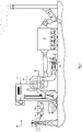
- FIG. 1 An example power plant 10 of a type that may incorporate a rotary heat exchanger 12 with heat transfer elements according to the present invention is illustrated in Fig. 1 .
- the power plant 10 includes a generator 14 coupled with a steam turbine 16 to produce electricity.
- the turbine 16 is driven by steam from a boiler 18, which receives air for combustion via an air intake 20 and expels combustion gases via an exhaust 22.
- Fans 24a and 24b may be used to supply air to the boiler intake 20 and to draw combustion gases from the exhaust 22 through a dust removal system 26 before it is released to the atmosphere.
- a rotary regenerative heat exchanger 12 may be positioned adjacent the air intake 20 and the exhaust 22 to preheat air entering the boiler 18 using heat from combustion gases expelled from the boiler.
- Rotary regenerative heat exchangers may also be used in gas-gas heaters to control emissions from the plant.
- the rotary heat exchanger 12 includes a housing 28 with a first duct or opening 30 and a second duct or opening 32.
- the first opening 30 communicates with the boiler air intake 20 and the second opening 32 communicates with the boiler exhaust 22.
- a rotor 34 containing a plurality of heat transfer element containers 36 is mounted for rotation in the housing 28 such that the heat transfer element containers 36 in the rotor circulate past the openings 30 and 32, thus causing heat transfer elements in the containers to be heated by exhaust gases when aligned with the second opening and preheating incoming air when aligned with the first opening.
- Fig. 3 is a perspective view of a heat transfer element container or pack 36 for a rotary heat exchanger according to an example embodiment of the present invention.
- the heat transfer element container 36 includes a plurality of heat transfer elements 38 in the form of sheets or plates arranged in a stack between a pair of support members 40.
- the support members may be end plates.
- the sheets are rectangular sheets oriented vertically between horizontally spaced end plates. The sheets are of the same height and of increasing width in a horizontal direction to provide a trapezoidal cross-section when viewed from above.
- the trapezoidal shape of the container 36 in this example permits multiple containers of this type to be arranged in a circular pattern or ring within a rotor of a rotary heat exchanger.
- the example heat transfer element container 36 may also include one or more support bars 42 extending above and below the heat transfer elements 38 between the support members 40 to help provide structural support for the assembly and/or one or more stiffening bars 44 extending transversely across the one or more support bars 42 for additional support.
- One or more steel bands 46 may be wrapped around the assembly to help retain the elements 38 in position during transportation. Any of the heat transfer elements described herein may be used in such a container.
- Fig. 4 is a planar view of a heat transfer element 38 according to an example embodiment of the present invention.
- the heat transfer element 38 comprises a rectangular sheet or plate formed of a thermally conductive material, such as steels, that can withstand being repeatedly heated to high temperatures when exposed to exhaust gases and cooled when exposed to incoming air at ambient temperature.
- a plurality of ribs or notches 48 are formed in the sheet at a first angle ⁇ 1 relative to the direction of air or gas flowing through the heat transfer element container (e.g., by feeding sheet stock through a pair of rollers with notched profiles).
- the notches 48 may be parallel as shown, with a first pitch Pi between notches.
- each notch 48 has a peak with a first height Hi and a trough with a first depth Di, which are selected to establish a desired spacing between stacked elements.
- the spacing between stacked elements is chosen to define a channel through which air and/or exhaust gases can flow.
- a plurality of undulations 50 are also formed in the sheet between the notches 48 (e.g., by feeding sheet stock through a pair of rollers with undulated profiles beforeor simultaneously as the notches are formed).
- the undulations 50 are configured to induce turbulence in the air and/or gas flowing through the channel defined between adjacent heat transfer elements 38.
- the undulations 50 are oriented at a second angle ⁇ 2 relative to the direction of air or gas flowing through the heat transfer element container.
- the second angle ⁇ 2 is selected to be in a direction opposite the first angle ⁇ 1 relative to the flow direction (e.g., clockwise vs. counterclockwise) so that the undulations 50 cross the notches 48.
- the second angle may be measured clockwise from the direction of air/gas flow.
- the undulations 50 may be parallel to one another as shown, with a second pitch P 2 that is smaller than the first pitch Pi.
- the undulations 50 may each have a second height H 2 that is smaller than the first height Hi and a second depth D 2 that is smaller than the first depth D 1 .
- the first angle ⁇ 1 may be in the range of 5° to 45°, and the second angle ⁇ 2 may be in the range of 0° to -90°. In another example, the first angle ⁇ 1 may be 20° and the second angle ⁇ 2 may be -30°.
- the first height Hi and depth Di may each be 5 - 9 mm
- the second height and depth H 2 and D 2 may each be 3 mm
- the first pitch Pi may be 35 mm
- the second pitch P 2 may be 15 mm.
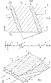
- Fig. 5 is a perspective view of a pair of heat transfer elements 38 and 38' stacked according to an example embodiment of the present invention.
- the first heat transfer element 38 is shown in partial cutaway so that details of the second heat transfer element 38' can be seen.
- Both heat transfer elements 38 and 38' have a configuration as shown in Figure 4 . However, their respective orientations relative to the direction of air flow are reversed relative to one another. That is, the first heat transfer element 38 has a first orientation and the second heat transfer element 38' has a second orientation that is rotated 180° relative to the first orientation so that the diagonally spaced notches on one heat transfer element cross the diagonally spaced notches on adjacent heat transfer elements and so on through the stack.
- the diagonally spaced crossed notches 48 and 48' perform the function of keeping a desired gap or spacing between adjacent heat transfer elements.
- the number of notches, their angle and their pitch contribute to having sufficient contact points to achieve a good tight, rigid pack when compressed.
- the diagonal crossing of the notches 48 and 48' also helps avoid skew flow, keeping an even flow across the full cross sectional flow area of the element pack.
- the angled undulations 50 and 50' between the notches in respective heat transfer elements 38 and 38' act as turbulators to induce turbulence.
- the turbulence inducing angled undulations 50 and 50' are incorporated to improve heat transfer, particularly at lower gas velocities and Reynolds Numbers.
- High efficiency heat transfer elements of the type described herein are thus suitable for fracked gas firing, in which flue gas exit temperatures may be significantly reduced in comparison with conventional coal fired boilers.
- the increased pressure drop resulting from higher turbulence is minimal and the heat rate benefits far outweigh any slight fan power increase that may be required.
- the clean flue gas will also not cause fouling so there is no tendency for pressure drop drift.
- a stack may comprise more than two heat transfer elements of alternating orientation as shown.
- the heat transfer elements shown in Fig. 5 may be stacked in an alternating manner with each other or with any of the other heat transfer elements described herein.
- Fig. 6 is a perspective view of a pair of stacked heat transfer elements 52 and 52' according to another example not forming part of the present invention.
- the heat transfer elements 52 and 52' are configured the same but are of reversed orientation.
- Each of the heat transfer elements 52 and 52' includes a plurality of angled notches 48 or 48', respectively, separated by a plurality of dimples 54 or 54', respectively.
- the angled notches 48 and 48' are the same as described above.
- dimples 54 and 54' are formed in between the notches 48 and 48' (e.g., by feeding sheet stock through a pair of dimpled rollers before or simultaneously as the notches are formed), instead of undulations.
- the dimples 54 and 54' may be hemispherical and either concave or convex.
- two or three rows of dimples are formed between each pair of angled notches. The rows may be parallel to the notches as shown or oriented at an angle relative to the notches. Dimples in adjacent rows may be aligned with each other or staggered.
- the depth of the dimples is less than the height/depth of the notches, and the spacing between adjacent dimples is smaller than the spacing between the notches.
- the dimples between the notches act as turbulators to induce turbulence. The turbulence inducing dimples improve heat transfer to facilitate use in fracked gas firing and other applications.
- a stack may comprise more than two heat transfer elements of alternating orientation as shown.
- the heat transfer elements of Fig. 6 may be stacked in an alternating manner with any of the other heat transfer elements described herein.
- Fig. 7 is a planar view of heat transfer element 56 according to yet another example not forming part of the present invention.
- Fig. 7A is a cross-sectional view of the heat transfer element 56 of Fig. 7 taken through section 7A-7A.
- the heat transfer element 56 includes a pair of notches 48 oriented parallel to the direction of air flow and a plurality of dimples 54 formed in between the notches.
- the dimples 54 are arranged in two columns of angled rows, with each row comprising three dimples and being oriented at an angle relative to the direction of air and/or gas flow.
- the rows of dimples 54 are each arranged at an angle of about 45° relative to the direction of air and/or gas flow.
- the dimples in the heat transfer element of Fig. 7 may be hemispherical in shape and may have a depth less than the height/depth of the notches, and a spacing between adjacent dimples that is smaller than the spacing between the notches.
- the dimples between the notches act as turbulators to induce turbulence.
- the turbulence inducing dimples improve heat transfer to facilitate use in fracked gas firing and other applications.
- the heat transfer element of Fig. 7 may be stacked in an alternating manner with the heat transfer element of Fig. 6 or with any of the other heat transfer elements described herein.
- Fig. 8 is a planar view of a heat transfer element 58 according to still another example not forming part of the present invention.
- Fig. 8A is a cross-sectional view of the heat transfer element 58 of Fig. 8 taken through section 8A-8A.
- a plurality of dimples 54 are formed in the heat transfer element 58 in a plurality of columns and rows.
- at least three columns of rows comprising three dimples each are shown.
- the rows may contain fewer or more dimples than shown.
- the rows of dimples are oriented at an angle relative to the direction of air flow.
- the rows of dimples are arranged at an angle of about 45° relative to the direction of air flow.
- the dimples act as turbulators to induce turbulence.
- the turbulence inducing dimples improve heat transfer to facilitate use in fracked gas firing and other applications.
- the heat transfer element of Fig. 8 may be stacked in an alternating manner with the heat transfer element of Fig. 7 or with any of the other heat transfer elements described herein.
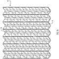
- Fig. 9 is a perspective view of a heat transfer element 60 according to a further example not forming part of the present invention.
- the heat transfer element 60 of Fig. 9 includes a repeating pattern of diamond shaped bumps or ridges 62 that serve as turbulators to induce turbulence.
- the turbulence inducing diamond pattern 62 increases the number of contact points and improves heat transfer to facilitate use in fracked gas firing and other applications.
- the diamond shaped bumps or ridges 62 may be formed by double rolling a sheet with the angle of the undulations on the first roller opposite the angle of the undulations on the second roller.
- the first roller may be configured to produce undulations oriented at an angle of +30° relative to the direction of air/gas flow and the second roller may be configured to produce undulations oriented at an angle of -30° relative to the direction of air/gas flow.
- This process results in a diamond profile and the angles of the undulations can be varied to alter the diamond shape.
- the heat transfer element of Fig. 9 may be stacked in an alternating manner with the heat transfer element of Fig. 7 , with a heat transfer element having an undulating or corrugated profile parallel to the direction of air/gas flow, or with any of the other heat transfer elements described herein.
- Fig. 10 is a perspective view of a heat transfer element 64 according to an additional example not forming part of the present invention.
- the heat transfer element 64 of Fig. 10 includes a complex pattern of bumps or ridges 66 that serve as turbulators to induce turbulence.
- the turbulence inducing pattern of Fig. 10 increases the number of contact points and improves heat transfer to facilitate use in fracked gas firing and other applications.
- the pattern shown in Fig. 10 may be formed by putting a sheet through an undulated roller to produce undulations oriented at an angle relative to the direction of air/gas flow, followed by a corrugated roller that produces corrugations oriented parallel to the direction of air/gas flow.
- the heat transfer element of Fig. 10 may be stacked in an alternating manner with a heat transfer element having angled undulations (e.g., oriented at an angle opposite the undulations in the heat transfer element of Fig. 10 ), with the heat transfer element of Fig. 9 , or with any of the other heat transfer elements described herein.
- the embodiments described above and illustrated in the drawings represent only a few of the many ways of implementing embodiments of the present invention.
- the angle of the undulations relative to the notch angles and the height of the undulations relative to the notch height can be varied to optimize heat transfer/pressure drop performance depending on the particular application or client specification.
- the dimples have been described as being hemispherical, it will be appreciated that they may comprise a smaller spherical segment (e.g., the height or depth of the dimples may be less than the radius) or have other configurations such as a pyramidal shape.
- heat transfer element container having a trapezoidal cross section
- the container can be configured to have a rectangular cross-section, a curved cross-section, or any other shape suitable for installation in a rotary heat exchanger.
Landscapes
- Engineering & Computer Science (AREA)
- Physics & Mathematics (AREA)
- Thermal Sciences (AREA)
- Mechanical Engineering (AREA)
- General Engineering & Computer Science (AREA)
- Heat-Exchange Devices With Radiators And Conduit Assemblies (AREA)
Priority Applications (1)
| Application Number | Priority Date | Filing Date | Title |
|---|---|---|---|
| EP22183823.8A EP4095473B1 (en) | 2017-06-29 | 2018-06-18 | Heat transfer elements for rotary heat exchangers |
Applications Claiming Priority (3)
| Application Number | Priority Date | Filing Date | Title |
|---|---|---|---|
| US15/636,673 US10837714B2 (en) | 2017-06-29 | 2017-06-29 | Heat transfer elements for rotary heat exchangers |
| US15/703,092 US10837715B2 (en) | 2017-06-29 | 2017-09-13 | Heat transfer elements for rotary heat exchangers |
| PCT/IB2018/054477 WO2019003044A1 (en) | 2017-06-29 | 2018-06-18 | HEAT TRANSFER ELEMENTS FOR ROTARY HEAT EXCHANGERS |
Related Child Applications (2)
| Application Number | Title | Priority Date | Filing Date |
|---|---|---|---|
| EP22183823.8A Division-Into EP4095473B1 (en) | 2017-06-29 | 2018-06-18 | Heat transfer elements for rotary heat exchangers |
| EP22183823.8A Division EP4095473B1 (en) | 2017-06-29 | 2018-06-18 | Heat transfer elements for rotary heat exchangers |
Publications (2)
| Publication Number | Publication Date |
|---|---|
| EP3645954A1 EP3645954A1 (en) | 2020-05-06 |
| EP3645954B1 true EP3645954B1 (en) | 2022-08-24 |
Family
ID=64738580
Family Applications (2)
| Application Number | Title | Priority Date | Filing Date |
|---|---|---|---|
| EP18746286.6A Active EP3645954B1 (en) | 2017-06-29 | 2018-06-18 | Heat transfer elements for rotary heat exchangers |
| EP22183823.8A Active EP4095473B1 (en) | 2017-06-29 | 2018-06-18 | Heat transfer elements for rotary heat exchangers |
Family Applications After (1)
| Application Number | Title | Priority Date | Filing Date |
|---|---|---|---|
| EP22183823.8A Active EP4095473B1 (en) | 2017-06-29 | 2018-06-18 | Heat transfer elements for rotary heat exchangers |
Country Status (9)
| Country | Link |
|---|---|
| US (2) | US10837714B2 (pl) |
| EP (2) | EP3645954B1 (pl) |
| JP (3) | JP7198230B2 (pl) |
| CN (1) | CN110799798A (pl) |
| CA (2) | CA3146402C (pl) |
| ES (1) | ES2927509T3 (pl) |
| MX (2) | MX394198B (pl) |
| PL (1) | PL3645954T3 (pl) |
| WO (1) | WO2019003044A1 (pl) |
Families Citing this family (3)
| Publication number | Priority date | Publication date | Assignee | Title |
|---|---|---|---|---|
| GB2570627B (en) * | 2017-11-03 | 2020-02-19 | Intersurgical Ag | Heat and moisture exchange media |
| CN113339992B (zh) * | 2021-06-02 | 2025-07-29 | 中山市骏伟电器有限公司 | 热交换模块及新风机 |
| CN113405117B (zh) * | 2021-06-08 | 2022-11-29 | 国家能源集团国源电力有限公司 | 空气预热设备 |
Family Cites Families (35)
| Publication number | Priority date | Publication date | Assignee | Title |
|---|---|---|---|---|
| US2438851A (en) | 1943-11-01 | 1948-03-30 | Air Preheater | Plate arrangement for preheaters |
| SE127755C1 (sv) * | 1945-05-28 | 1950-03-28 | Ljungstroms Angturbin Ab | Elementsats för värmeväxlare |
| US2940736A (en) * | 1949-05-25 | 1960-06-14 | Svenska Rotor Maskiner Ab | Element set for heat exchangers |
| US4449573A (en) | 1969-06-16 | 1984-05-22 | Svenska Rotor Maskiner Aktiebolag | Regenerative heat exchangers |
| GB2060657B (en) | 1979-10-22 | 1983-03-09 | Dulux Australia Ltd | Water-miscible crosslinkable coating compositions |
| SE8206246L (sv) * | 1981-11-12 | 1983-05-13 | Northern Solar Systems Inc | Roterande vermevexlare |
| US4396058A (en) * | 1981-11-23 | 1983-08-02 | The Air Preheater Company | Heat transfer element assembly |
| US4553458A (en) | 1984-03-28 | 1985-11-19 | The Air Preheater Company, Inc. | Method for manufacturing heat transfer element sheets for a rotary regenerative heat exchanger |
| SE459826B (sv) * | 1984-10-03 | 1989-08-07 | Munters Ab Carl | Insatskropp av veckade skikt med speciellt utformade kantpartier |
| US4744410A (en) * | 1987-02-24 | 1988-05-17 | The Air Preheater Company, Inc. | Heat transfer element assembly |
| SE455883B (sv) * | 1987-02-27 | 1988-08-15 | Svenska Rotor Maskiner Ab | Sats av vermeoverforingsplatar, der platarnas dubbelasar har en specifik inbordes orientering |
| US4838342A (en) | 1988-06-01 | 1989-06-13 | The Air Preheater Company, Inc. | Element basket assembly for heat exchanger |
| US4930569A (en) * | 1989-10-25 | 1990-06-05 | The Air Preheater Company, Inc. | Heat transfer element assembly |
| DE19528634A1 (de) | 1995-08-04 | 1997-02-06 | Rothemuehle Brandt Kritzler | Heizblechpaket für Regenerativ-Wärmetauscher |
| JPH09280761A (ja) | 1996-04-09 | 1997-10-31 | Abb Kk | 伝熱要素板の積層体を備えた熱交換器 |
| US5803158A (en) * | 1996-10-04 | 1998-09-08 | Abb Air Preheater, Inc. | Air preheater heat transfer surface |
| US5836379A (en) * | 1996-11-22 | 1998-11-17 | Abb Air Preheater, Inc. | Air preheater heat transfer surface |
| DE19652999C2 (de) * | 1996-12-19 | 1999-06-24 | Steag Ag | Wärmespeicherblock für regenerative Wärmetauscher |
| US5979050A (en) * | 1997-06-13 | 1999-11-09 | Abb Air Preheater, Inc. | Air preheater heat transfer elements and method of manufacture |
| US5899261A (en) * | 1997-09-15 | 1999-05-04 | Abb Air Preheater, Inc. | Air preheater heat transfer surface |
| US6019160A (en) * | 1998-12-16 | 2000-02-01 | Abb Air Preheater, Inc. | Heat transfer element assembly |
| US6179276B1 (en) * | 1999-02-17 | 2001-01-30 | Abb Air Preheater, Inc. | Heat and mass transfer element assembly |
| US6516871B1 (en) | 1999-08-18 | 2003-02-11 | Alstom (Switzerland) Ltd. | Heat transfer element assembly |
| US6892795B1 (en) * | 2000-10-04 | 2005-05-17 | Airxchange, Inc. | Embossed regenerator matrix for heat exchanger |
| DE60320681T2 (de) | 2002-10-31 | 2009-06-10 | Sharp K.K. | Regenerator, verfahren zur herstellung des regenerators, system zur herstellung des regenerators und stirling-kältemaschine |
| GB2429054A (en) | 2005-07-29 | 2007-02-14 | Howden Power Ltd | A heating surface element |
| US20090250201A1 (en) | 2008-04-02 | 2009-10-08 | Grippe Frank M | Heat exchanger having a contoured insert and method of assembling the same |
| US9557119B2 (en) | 2009-05-08 | 2017-01-31 | Arvos Inc. | Heat transfer sheet for rotary regenerative heat exchanger |
| US8622115B2 (en) * | 2009-08-19 | 2014-01-07 | Alstom Technology Ltd | Heat transfer element for a rotary regenerative heat exchanger |
| TWM381055U (en) | 2009-11-25 | 2010-05-21 | Asia Vital Components Co Ltd | Fin structure for heat exchanger and heat exchanger thereof |
| US9644899B2 (en) | 2011-06-01 | 2017-05-09 | Arvos, Inc. | Heating element undulation patterns |
| US9921000B2 (en) * | 2011-07-22 | 2018-03-20 | 8 Rivers Capital, Llc | Heat exchanger comprising one or more plate assemblies with a plurality of interconnected channels and related method |
| JP6312355B2 (ja) * | 2012-08-24 | 2018-04-18 | 三菱重工サーマルシステムズ株式会社 | 熱交換器 |
| US10175006B2 (en) * | 2013-11-25 | 2019-01-08 | Arvos Ljungstrom Llc | Heat transfer elements for a closed channel rotary regenerative air preheater |
| US10094626B2 (en) | 2015-10-07 | 2018-10-09 | Arvos Ljungstrom Llc | Alternating notch configuration for spacing heat transfer sheets |
-
2017
- 2017-06-29 US US15/636,673 patent/US10837714B2/en active Active
- 2017-09-13 US US15/703,092 patent/US10837715B2/en active Active
-
2018
- 2018-06-18 JP JP2019572502A patent/JP7198230B2/ja active Active
- 2018-06-18 EP EP18746286.6A patent/EP3645954B1/en active Active
- 2018-06-18 MX MX2019014496A patent/MX394198B/es unknown
- 2018-06-18 CN CN201880043272.6A patent/CN110799798A/zh active Pending
- 2018-06-18 PL PL18746286.6T patent/PL3645954T3/pl unknown
- 2018-06-18 WO PCT/IB2018/054477 patent/WO2019003044A1/en not_active Ceased
- 2018-06-18 CA CA3146402A patent/CA3146402C/en active Active
- 2018-06-18 CA CA3066702A patent/CA3066702C/en active Active
- 2018-06-18 EP EP22183823.8A patent/EP4095473B1/en active Active
- 2018-06-18 ES ES18746286T patent/ES2927509T3/es active Active
-
2019
- 2019-12-02 MX MX2022002048A patent/MX2022002048A/es unknown
-
2022
- 2022-01-07 JP JP2022001421A patent/JP7514866B2/ja active Active
- 2022-01-07 JP JP2022001422A patent/JP2022043312A/ja not_active Withdrawn
Non-Patent Citations (2)
| Title |
|---|
| ALSTOM: "DUN Advanced Heating surface", 21 December 2013 (2013-12-21), XP055830726, Retrieved from the Internet <URL:https://diplus.internal.epo.org/app/?num=EP18746286&type=application&format=original> [retrieved on 20210806] * |
| ALSTOM: "The DN7 Advanced Air Preheater Surface", 31 December 2005 (2005-12-31), XP055830689, Retrieved from the Internet <URL:https://diplus.internal.epo.org/app/?num=EP18746286&type=application&format=original> [retrieved on 20210806] * |
Also Published As
| Publication number | Publication date |
|---|---|
| US10837714B2 (en) | 2020-11-17 |
| US20190003778A1 (en) | 2019-01-03 |
| CA3146402C (en) | 2023-07-25 |
| CA3066702C (en) | 2022-05-03 |
| JP2020525750A (ja) | 2020-08-27 |
| EP4095473A1 (en) | 2022-11-30 |
| ES2927509T3 (es) | 2022-11-07 |
| JP2022043312A (ja) | 2022-03-15 |
| WO2019003044A1 (en) | 2019-01-03 |
| PL3645954T3 (pl) | 2023-01-16 |
| EP4095473B1 (en) | 2025-11-05 |
| JP2022043311A (ja) | 2022-03-15 |
| US20190003779A1 (en) | 2019-01-03 |
| MX2019014496A (es) | 2020-02-20 |
| JP7198230B2 (ja) | 2022-12-28 |
| MX2022002048A (es) | 2022-03-11 |
| MX394198B (es) | 2025-03-24 |
| CA3146402A1 (en) | 2019-01-03 |
| CN110799798A (zh) | 2020-02-14 |
| US10837715B2 (en) | 2020-11-17 |
| JP7514866B2 (ja) | 2024-07-11 |
| EP3645954A1 (en) | 2020-05-06 |
| CA3066702A1 (en) | 2019-01-03 |
Similar Documents
| Publication | Publication Date | Title |
|---|---|---|
| KR100445821B1 (ko) | 열 및 물질 전달 요소 조립체 | |
| JP7514866B2 (ja) | 回転式熱交換器用熱伝達エレメント | |
| EP1144932B1 (en) | Heat transfer element assembly | |
| US4744410A (en) | Heat transfer element assembly | |
| EP2667138B1 (en) | Heat transfer sheet for rotary regenerative heat exchanger | |
| EP1910766B1 (en) | Heat exchange surface | |
| US4930569A (en) | Heat transfer element assembly | |
| JP6050567B2 (ja) | フィン管式熱交換器 | |
| WO2004040221A1 (en) | Air preheater heat transfer elements |
Legal Events
| Date | Code | Title | Description |
|---|---|---|---|
| STAA | Information on the status of an ep patent application or granted ep patent |
Free format text: STATUS: UNKNOWN |
|
| STAA | Information on the status of an ep patent application or granted ep patent |
Free format text: STATUS: THE INTERNATIONAL PUBLICATION HAS BEEN MADE |
|
| PUAI | Public reference made under article 153(3) epc to a published international application that has entered the european phase |
Free format text: ORIGINAL CODE: 0009012 |
|
| STAA | Information on the status of an ep patent application or granted ep patent |
Free format text: STATUS: REQUEST FOR EXAMINATION WAS MADE |
|
| 17P | Request for examination filed |
Effective date: 20191115 |
|
| AK | Designated contracting states |
Kind code of ref document: A1 Designated state(s): AL AT BE BG CH CY CZ DE DK EE ES FI FR GB GR HR HU IE IS IT LI LT LU LV MC MK MT NL NO PL PT RO RS SE SI SK SM TR |
|
| AX | Request for extension of the european patent |
Extension state: BA ME |
|
| DAV | Request for validation of the european patent (deleted) | ||
| DAX | Request for extension of the european patent (deleted) | ||
| STAA | Information on the status of an ep patent application or granted ep patent |
Free format text: STATUS: EXAMINATION IS IN PROGRESS |
|
| 17Q | First examination report despatched |
Effective date: 20201022 |
|
| TPAC | Observations filed by third parties |
Free format text: ORIGINAL CODE: EPIDOSNTIPA |
|
| GRAP | Despatch of communication of intention to grant a patent |
Free format text: ORIGINAL CODE: EPIDOSNIGR1 |
|
| STAA | Information on the status of an ep patent application or granted ep patent |
Free format text: STATUS: GRANT OF PATENT IS INTENDED |
|
| INTG | Intention to grant announced |
Effective date: 20220317 |
|
| RIN1 | Information on inventor provided before grant (corrected) |
Inventor name: HOGG, DOUGAL Inventor name: REID, MERON |
|
| GRAS | Grant fee paid |
Free format text: ORIGINAL CODE: EPIDOSNIGR3 |
|
| GRAA | (expected) grant |
Free format text: ORIGINAL CODE: 0009210 |
|
| STAA | Information on the status of an ep patent application or granted ep patent |
Free format text: STATUS: THE PATENT HAS BEEN GRANTED |
|
| AK | Designated contracting states |
Kind code of ref document: B1 Designated state(s): AL AT BE BG CH CY CZ DE DK EE ES FI FR GB GR HR HU IE IS IT LI LT LU LV MC MK MT NL NO PL PT RO RS SE SI SK SM TR |
|
| REG | Reference to a national code |
Ref country code: CH Ref legal event code: EP |
|
| REG | Reference to a national code |
Ref country code: DE Ref legal event code: R096 Ref document number: 602018039724 Country of ref document: DE |
|
| REG | Reference to a national code |
Ref country code: IE Ref legal event code: FG4D |
|
| REG | Reference to a national code |
Ref country code: AT Ref legal event code: REF Ref document number: 1513932 Country of ref document: AT Kind code of ref document: T Effective date: 20220915 |
|
| REG | Reference to a national code |
Ref country code: ES Ref legal event code: FG2A Ref document number: 2927509 Country of ref document: ES Kind code of ref document: T3 Effective date: 20221107 |
|
| REG | Reference to a national code |
Ref country code: LT Ref legal event code: MG9D |
|
| REG | Reference to a national code |
Ref country code: NL Ref legal event code: MP Effective date: 20220824 |
|
| PG25 | Lapsed in a contracting state [announced via postgrant information from national office to epo] |
Ref country code: SE Free format text: LAPSE BECAUSE OF FAILURE TO SUBMIT A TRANSLATION OF THE DESCRIPTION OR TO PAY THE FEE WITHIN THE PRESCRIBED TIME-LIMIT Effective date: 20220824 Ref country code: RS Free format text: LAPSE BECAUSE OF FAILURE TO SUBMIT A TRANSLATION OF THE DESCRIPTION OR TO PAY THE FEE WITHIN THE PRESCRIBED TIME-LIMIT Effective date: 20220824 Ref country code: PT Free format text: LAPSE BECAUSE OF FAILURE TO SUBMIT A TRANSLATION OF THE DESCRIPTION OR TO PAY THE FEE WITHIN THE PRESCRIBED TIME-LIMIT Effective date: 20221226 Ref country code: NO Free format text: LAPSE BECAUSE OF FAILURE TO SUBMIT A TRANSLATION OF THE DESCRIPTION OR TO PAY THE FEE WITHIN THE PRESCRIBED TIME-LIMIT Effective date: 20221124 Ref country code: NL Free format text: LAPSE BECAUSE OF FAILURE TO SUBMIT A TRANSLATION OF THE DESCRIPTION OR TO PAY THE FEE WITHIN THE PRESCRIBED TIME-LIMIT Effective date: 20220824 Ref country code: LV Free format text: LAPSE BECAUSE OF FAILURE TO SUBMIT A TRANSLATION OF THE DESCRIPTION OR TO PAY THE FEE WITHIN THE PRESCRIBED TIME-LIMIT Effective date: 20220824 Ref country code: LT Free format text: LAPSE BECAUSE OF FAILURE TO SUBMIT A TRANSLATION OF THE DESCRIPTION OR TO PAY THE FEE WITHIN THE PRESCRIBED TIME-LIMIT Effective date: 20220824 Ref country code: FI Free format text: LAPSE BECAUSE OF FAILURE TO SUBMIT A TRANSLATION OF THE DESCRIPTION OR TO PAY THE FEE WITHIN THE PRESCRIBED TIME-LIMIT Effective date: 20220824 |
|
| PG25 | Lapsed in a contracting state [announced via postgrant information from national office to epo] |
Ref country code: IS Free format text: LAPSE BECAUSE OF FAILURE TO SUBMIT A TRANSLATION OF THE DESCRIPTION OR TO PAY THE FEE WITHIN THE PRESCRIBED TIME-LIMIT Effective date: 20221224 Ref country code: HR Free format text: LAPSE BECAUSE OF FAILURE TO SUBMIT A TRANSLATION OF THE DESCRIPTION OR TO PAY THE FEE WITHIN THE PRESCRIBED TIME-LIMIT Effective date: 20220824 Ref country code: GR Free format text: LAPSE BECAUSE OF FAILURE TO SUBMIT A TRANSLATION OF THE DESCRIPTION OR TO PAY THE FEE WITHIN THE PRESCRIBED TIME-LIMIT Effective date: 20221125 |
|
| PG25 | Lapsed in a contracting state [announced via postgrant information from national office to epo] |
Ref country code: SM Free format text: LAPSE BECAUSE OF FAILURE TO SUBMIT A TRANSLATION OF THE DESCRIPTION OR TO PAY THE FEE WITHIN THE PRESCRIBED TIME-LIMIT Effective date: 20220824 Ref country code: RO Free format text: LAPSE BECAUSE OF FAILURE TO SUBMIT A TRANSLATION OF THE DESCRIPTION OR TO PAY THE FEE WITHIN THE PRESCRIBED TIME-LIMIT Effective date: 20220824 Ref country code: DK Free format text: LAPSE BECAUSE OF FAILURE TO SUBMIT A TRANSLATION OF THE DESCRIPTION OR TO PAY THE FEE WITHIN THE PRESCRIBED TIME-LIMIT Effective date: 20220824 Ref country code: CZ Free format text: LAPSE BECAUSE OF FAILURE TO SUBMIT A TRANSLATION OF THE DESCRIPTION OR TO PAY THE FEE WITHIN THE PRESCRIBED TIME-LIMIT Effective date: 20220824 |
|
| REG | Reference to a national code |
Ref country code: DE Ref legal event code: R097 Ref document number: 602018039724 Country of ref document: DE |
|
| PG25 | Lapsed in a contracting state [announced via postgrant information from national office to epo] |
Ref country code: SK Free format text: LAPSE BECAUSE OF FAILURE TO SUBMIT A TRANSLATION OF THE DESCRIPTION OR TO PAY THE FEE WITHIN THE PRESCRIBED TIME-LIMIT Effective date: 20220824 Ref country code: EE Free format text: LAPSE BECAUSE OF FAILURE TO SUBMIT A TRANSLATION OF THE DESCRIPTION OR TO PAY THE FEE WITHIN THE PRESCRIBED TIME-LIMIT Effective date: 20220824 |
|
| PG25 | Lapsed in a contracting state [announced via postgrant information from national office to epo] |
Ref country code: AL Free format text: LAPSE BECAUSE OF FAILURE TO SUBMIT A TRANSLATION OF THE DESCRIPTION OR TO PAY THE FEE WITHIN THE PRESCRIBED TIME-LIMIT Effective date: 20220824 |
|
| PLBE | No opposition filed within time limit |
Free format text: ORIGINAL CODE: 0009261 |
|
| STAA | Information on the status of an ep patent application or granted ep patent |
Free format text: STATUS: NO OPPOSITION FILED WITHIN TIME LIMIT |
|
| P01 | Opt-out of the competence of the unified patent court (upc) registered |
Effective date: 20230531 |
|
| 26N | No opposition filed |
Effective date: 20230525 |
|
| PG25 | Lapsed in a contracting state [announced via postgrant information from national office to epo] |
Ref country code: SI Free format text: LAPSE BECAUSE OF FAILURE TO SUBMIT A TRANSLATION OF THE DESCRIPTION OR TO PAY THE FEE WITHIN THE PRESCRIBED TIME-LIMIT Effective date: 20220824 |
|
| REG | Reference to a national code |
Ref country code: AT Ref legal event code: UEP Ref document number: 1513932 Country of ref document: AT Kind code of ref document: T Effective date: 20220824 |
|
| PG25 | Lapsed in a contracting state [announced via postgrant information from national office to epo] |
Ref country code: MC Free format text: LAPSE BECAUSE OF FAILURE TO SUBMIT A TRANSLATION OF THE DESCRIPTION OR TO PAY THE FEE WITHIN THE PRESCRIBED TIME-LIMIT Effective date: 20220824 |
|
| PG25 | Lapsed in a contracting state [announced via postgrant information from national office to epo] |
Ref country code: MC Free format text: LAPSE BECAUSE OF FAILURE TO SUBMIT A TRANSLATION OF THE DESCRIPTION OR TO PAY THE FEE WITHIN THE PRESCRIBED TIME-LIMIT Effective date: 20220824 |
|
| REG | Reference to a national code |
Ref country code: CH Ref legal event code: PL |
|
| PG25 | Lapsed in a contracting state [announced via postgrant information from national office to epo] |
Ref country code: LU Free format text: LAPSE BECAUSE OF NON-PAYMENT OF DUE FEES Effective date: 20230618 |
|
| REG | Reference to a national code |
Ref country code: IE Ref legal event code: MM4A |
|
| PG25 | Lapsed in a contracting state [announced via postgrant information from national office to epo] |
Ref country code: LU Free format text: LAPSE BECAUSE OF NON-PAYMENT OF DUE FEES Effective date: 20230618 |
|
| PG25 | Lapsed in a contracting state [announced via postgrant information from national office to epo] |
Ref country code: IE Free format text: LAPSE BECAUSE OF NON-PAYMENT OF DUE FEES Effective date: 20230618 |
|
| PG25 | Lapsed in a contracting state [announced via postgrant information from national office to epo] |
Ref country code: IE Free format text: LAPSE BECAUSE OF NON-PAYMENT OF DUE FEES Effective date: 20230618 Ref country code: CH Free format text: LAPSE BECAUSE OF NON-PAYMENT OF DUE FEES Effective date: 20230630 |
|
| PG25 | Lapsed in a contracting state [announced via postgrant information from national office to epo] |
Ref country code: BG Free format text: LAPSE BECAUSE OF FAILURE TO SUBMIT A TRANSLATION OF THE DESCRIPTION OR TO PAY THE FEE WITHIN THE PRESCRIBED TIME-LIMIT Effective date: 20220824 |
|
| PG25 | Lapsed in a contracting state [announced via postgrant information from national office to epo] |
Ref country code: BG Free format text: LAPSE BECAUSE OF FAILURE TO SUBMIT A TRANSLATION OF THE DESCRIPTION OR TO PAY THE FEE WITHIN THE PRESCRIBED TIME-LIMIT Effective date: 20220824 |
|
| PG25 | Lapsed in a contracting state [announced via postgrant information from national office to epo] |
Ref country code: CY Free format text: LAPSE BECAUSE OF FAILURE TO SUBMIT A TRANSLATION OF THE DESCRIPTION OR TO PAY THE FEE WITHIN THE PRESCRIBED TIME-LIMIT; INVALID AB INITIO Effective date: 20180618 |
|
| PG25 | Lapsed in a contracting state [announced via postgrant information from national office to epo] |
Ref country code: HU Free format text: LAPSE BECAUSE OF FAILURE TO SUBMIT A TRANSLATION OF THE DESCRIPTION OR TO PAY THE FEE WITHIN THE PRESCRIBED TIME-LIMIT; INVALID AB INITIO Effective date: 20180618 |
|
| PGFP | Annual fee paid to national office [announced via postgrant information from national office to epo] |
Ref country code: ES Payment date: 20250701 Year of fee payment: 8 |
|
| PG25 | Lapsed in a contracting state [announced via postgrant information from national office to epo] |
Ref country code: TR Free format text: LAPSE BECAUSE OF FAILURE TO SUBMIT A TRANSLATION OF THE DESCRIPTION OR TO PAY THE FEE WITHIN THE PRESCRIBED TIME-LIMIT Effective date: 20220824 |
|
| PGFP | Annual fee paid to national office [announced via postgrant information from national office to epo] |
Ref country code: PL Payment date: 20260603 Year of fee payment: 9 Ref country code: GB Payment date: 20260629 Year of fee payment: 9 |
|
| PGFP | Annual fee paid to national office [announced via postgrant information from national office to epo] |
Ref country code: IT Payment date: 20260622 Year of fee payment: 9 |
|
| PGFP | Annual fee paid to national office [announced via postgrant information from national office to epo] |
Ref country code: DE Payment date: 20260629 Year of fee payment: 9 |
|
| PGFP | Annual fee paid to national office [announced via postgrant information from national office to epo] |
Ref country code: AT Payment date: 20260629 Year of fee payment: 9 |
|
| PGFP | Annual fee paid to national office [announced via postgrant information from national office to epo] |
Ref country code: BE Payment date: 20260629 Year of fee payment: 9 |
|
| PGFP | Annual fee paid to national office [announced via postgrant information from national office to epo] |
Ref country code: FR Payment date: 20260625 Year of fee payment: 9 |