EP3646000B1 - Prüfvorrichtung zum ermitteln der partikelbelastung von unter einem hohen druck stehendem wasserstoff - Google Patents
Prüfvorrichtung zum ermitteln der partikelbelastung von unter einem hohen druck stehendem wasserstoff Download PDFInfo
- Publication number
- EP3646000B1 EP3646000B1 EP18734536.8A EP18734536A EP3646000B1 EP 3646000 B1 EP3646000 B1 EP 3646000B1 EP 18734536 A EP18734536 A EP 18734536A EP 3646000 B1 EP3646000 B1 EP 3646000B1
- Authority
- EP
- European Patent Office
- Prior art keywords
- test device
- test
- inlet
- hydrogen
- valve
- Prior art date
- Legal status (The legal status is an assumption and is not a legal conclusion. Google has not performed a legal analysis and makes no representation as to the accuracy of the status listed.)
- Active
Links
Images

Classifications
-
- G—PHYSICS
- G01—MEASURING; TESTING
- G01N—INVESTIGATING OR ANALYSING MATERIALS BY DETERMINING THEIR CHEMICAL OR PHYSICAL PROPERTIES
- G01N15/00—Investigating characteristics of particles; Investigating permeability, pore-volume or surface-area of porous materials
- G01N15/06—Investigating concentration of particle suspensions
- G01N15/0606—Investigating concentration of particle suspensions by collecting particles on a support
- G01N15/0618—Investigating concentration of particle suspensions by collecting particles on a support of the filter type
-
- F—MECHANICAL ENGINEERING; LIGHTING; HEATING; WEAPONS; BLASTING
- F17—STORING OR DISTRIBUTING GASES OR LIQUIDS
- F17C—VESSELS FOR CONTAINING OR STORING COMPRESSED, LIQUEFIED OR SOLIDIFIED GASES; FIXED-CAPACITY GAS-HOLDERS; FILLING VESSELS WITH, OR DISCHARGING FROM VESSELS, COMPRESSED, LIQUEFIED, OR SOLIDIFIED GASES
- F17C1/00—Pressure vessels, e.g. gas cylinder, gas tank, replaceable cartridge
-
- F—MECHANICAL ENGINEERING; LIGHTING; HEATING; WEAPONS; BLASTING
- F17—STORING OR DISTRIBUTING GASES OR LIQUIDS
- F17C—VESSELS FOR CONTAINING OR STORING COMPRESSED, LIQUEFIED OR SOLIDIFIED GASES; FIXED-CAPACITY GAS-HOLDERS; FILLING VESSELS WITH, OR DISCHARGING FROM VESSELS, COMPRESSED, LIQUEFIED, OR SOLIDIFIED GASES
- F17C13/00—Details of vessels or of the filling or discharging of vessels
-
- G—PHYSICS
- G01—MEASURING; TESTING
- G01N—INVESTIGATING OR ANALYSING MATERIALS BY DETERMINING THEIR CHEMICAL OR PHYSICAL PROPERTIES
- G01N1/00—Sampling; Preparing specimens for investigation
- G01N1/02—Devices for withdrawing samples
- G01N1/22—Devices for withdrawing samples in the gaseous state
- G01N1/2202—Devices for withdrawing samples in the gaseous state involving separation of sample components during sampling
- G01N1/2205—Devices for withdrawing samples in the gaseous state involving separation of sample components during sampling with filters
-
- F—MECHANICAL ENGINEERING; LIGHTING; HEATING; WEAPONS; BLASTING
- F17—STORING OR DISTRIBUTING GASES OR LIQUIDS
- F17C—VESSELS FOR CONTAINING OR STORING COMPRESSED, LIQUEFIED OR SOLIDIFIED GASES; FIXED-CAPACITY GAS-HOLDERS; FILLING VESSELS WITH, OR DISCHARGING FROM VESSELS, COMPRESSED, LIQUEFIED, OR SOLIDIFIED GASES
- F17C2205/00—Vessel construction, in particular mounting arrangements, attachments or identifications means
- F17C2205/03—Fluid connections, filters, valves, closure means or other attachments
- F17C2205/0302—Fittings, valves, filters, or components in connection with the gas storage device
- F17C2205/0323—Valves
- F17C2205/0335—Check-valves or non-return valves
-
- F—MECHANICAL ENGINEERING; LIGHTING; HEATING; WEAPONS; BLASTING
- F17—STORING OR DISTRIBUTING GASES OR LIQUIDS
- F17C—VESSELS FOR CONTAINING OR STORING COMPRESSED, LIQUEFIED OR SOLIDIFIED GASES; FIXED-CAPACITY GAS-HOLDERS; FILLING VESSELS WITH, OR DISCHARGING FROM VESSELS, COMPRESSED, LIQUEFIED, OR SOLIDIFIED GASES
- F17C2205/00—Vessel construction, in particular mounting arrangements, attachments or identifications means
- F17C2205/03—Fluid connections, filters, valves, closure means or other attachments
- F17C2205/0302—Fittings, valves, filters, or components in connection with the gas storage device
- F17C2205/0341—Filters
-
- F—MECHANICAL ENGINEERING; LIGHTING; HEATING; WEAPONS; BLASTING
- F17—STORING OR DISTRIBUTING GASES OR LIQUIDS
- F17C—VESSELS FOR CONTAINING OR STORING COMPRESSED, LIQUEFIED OR SOLIDIFIED GASES; FIXED-CAPACITY GAS-HOLDERS; FILLING VESSELS WITH, OR DISCHARGING FROM VESSELS, COMPRESSED, LIQUEFIED, OR SOLIDIFIED GASES
- F17C2205/00—Vessel construction, in particular mounting arrangements, attachments or identifications means
- F17C2205/03—Fluid connections, filters, valves, closure means or other attachments
- F17C2205/0302—Fittings, valves, filters, or components in connection with the gas storage device
- F17C2205/037—Quick connecting means, e.g. couplings
-
- F—MECHANICAL ENGINEERING; LIGHTING; HEATING; WEAPONS; BLASTING
- F17—STORING OR DISTRIBUTING GASES OR LIQUIDS
- F17C—VESSELS FOR CONTAINING OR STORING COMPRESSED, LIQUEFIED OR SOLIDIFIED GASES; FIXED-CAPACITY GAS-HOLDERS; FILLING VESSELS WITH, OR DISCHARGING FROM VESSELS, COMPRESSED, LIQUEFIED, OR SOLIDIFIED GASES
- F17C2221/00—Handled fluid, in particular type of fluid
- F17C2221/01—Pure fluids
- F17C2221/012—Hydrogen
-
- F—MECHANICAL ENGINEERING; LIGHTING; HEATING; WEAPONS; BLASTING
- F17—STORING OR DISTRIBUTING GASES OR LIQUIDS
- F17C—VESSELS FOR CONTAINING OR STORING COMPRESSED, LIQUEFIED OR SOLIDIFIED GASES; FIXED-CAPACITY GAS-HOLDERS; FILLING VESSELS WITH, OR DISCHARGING FROM VESSELS, COMPRESSED, LIQUEFIED, OR SOLIDIFIED GASES
- F17C2223/00—Handled fluid before transfer, i.e. state of fluid when stored in the vessel or before transfer from the vessel
- F17C2223/01—Handled fluid before transfer, i.e. state of fluid when stored in the vessel or before transfer from the vessel characterised by the phase
- F17C2223/0107—Single phase
- F17C2223/0123—Single phase gaseous, e.g. CNG, GNC
-
- F—MECHANICAL ENGINEERING; LIGHTING; HEATING; WEAPONS; BLASTING
- F17—STORING OR DISTRIBUTING GASES OR LIQUIDS
- F17C—VESSELS FOR CONTAINING OR STORING COMPRESSED, LIQUEFIED OR SOLIDIFIED GASES; FIXED-CAPACITY GAS-HOLDERS; FILLING VESSELS WITH, OR DISCHARGING FROM VESSELS, COMPRESSED, LIQUEFIED, OR SOLIDIFIED GASES
- F17C2223/00—Handled fluid before transfer, i.e. state of fluid when stored in the vessel or before transfer from the vessel
- F17C2223/03—Handled fluid before transfer, i.e. state of fluid when stored in the vessel or before transfer from the vessel characterised by the pressure level
- F17C2223/036—Very high pressure (>80 bar)
-
- F—MECHANICAL ENGINEERING; LIGHTING; HEATING; WEAPONS; BLASTING
- F17—STORING OR DISTRIBUTING GASES OR LIQUIDS
- F17C—VESSELS FOR CONTAINING OR STORING COMPRESSED, LIQUEFIED OR SOLIDIFIED GASES; FIXED-CAPACITY GAS-HOLDERS; FILLING VESSELS WITH, OR DISCHARGING FROM VESSELS, COMPRESSED, LIQUEFIED, OR SOLIDIFIED GASES
- F17C2250/00—Accessories; Control means; Indicating, measuring or monitoring of parameters
- F17C2250/04—Indicating or measuring of parameters as input values
- F17C2250/0404—Parameters indicated or measured
- F17C2250/0447—Composition; Humidity
-
- F—MECHANICAL ENGINEERING; LIGHTING; HEATING; WEAPONS; BLASTING
- F17—STORING OR DISTRIBUTING GASES OR LIQUIDS
- F17C—VESSELS FOR CONTAINING OR STORING COMPRESSED, LIQUEFIED OR SOLIDIFIED GASES; FIXED-CAPACITY GAS-HOLDERS; FILLING VESSELS WITH, OR DISCHARGING FROM VESSELS, COMPRESSED, LIQUEFIED, OR SOLIDIFIED GASES
- F17C2270/00—Applications
- F17C2270/01—Applications for fluid transport or storage
- F17C2270/0165—Applications for fluid transport or storage on the road
- F17C2270/0168—Applications for fluid transport or storage on the road by vehicles
-
- G—PHYSICS
- G01—MEASURING; TESTING
- G01N—INVESTIGATING OR ANALYSING MATERIALS BY DETERMINING THEIR CHEMICAL OR PHYSICAL PROPERTIES
- G01N1/00—Sampling; Preparing specimens for investigation
- G01N1/02—Devices for withdrawing samples
- G01N1/22—Devices for withdrawing samples in the gaseous state
- G01N1/2226—Sampling from a closed space, e.g. food package, head space
- G01N2001/2238—Sampling from a closed space, e.g. food package, head space the gas being compressed or pressurized
-
- Y—GENERAL TAGGING OF NEW TECHNOLOGICAL DEVELOPMENTS; GENERAL TAGGING OF CROSS-SECTIONAL TECHNOLOGIES SPANNING OVER SEVERAL SECTIONS OF THE IPC; TECHNICAL SUBJECTS COVERED BY FORMER USPC CROSS-REFERENCE ART COLLECTIONS [XRACs] AND DIGESTS
- Y02—TECHNOLOGIES OR APPLICATIONS FOR MITIGATION OR ADAPTATION AGAINST CLIMATE CHANGE
- Y02P—CLIMATE CHANGE MITIGATION TECHNOLOGIES IN THE PRODUCTION OR PROCESSING OF GOODS
- Y02P90/00—Enabling technologies with a potential contribution to greenhouse gas [GHG] emissions mitigation
- Y02P90/45—Hydrogen technologies in production processes
Definitions
- the invention relates to a test device for determining the particle load of hydrogen under high pressure, with a housing which has an inlet and an outlet for the inflow of the hydrogen or the outflow of the same and a sample chamber in which a filter holder for a test filter is provided is, through which a sample amount of hydrogen can flow during a test process and can be removed from the sample chamber for evaluating the accumulation of particles after the test process has ended, and with a venting device that enables the sample chamber to be depressurized.
- test device of this type is known, s. WO 2013/139462 A1 .
- Such devices can mainly be used for an application in hydrogen refueling systems, that is to say in particular in engine applications in which hydrogen is used as a gaseous fuel, or for the supply of fuel cells with hydrogen.
- hydrogen is used as a gaseous fuel
- the test for the absence of particles therefore makes an important contribution to ensuring safe operation of the facilities to be supplied with hydrogen.
- the test process is carried out in the course of a refueling process in which the inlet of the housing of the test device is connected to an H 2 filling station and the outlet is connected to a fuel nozzle via a tank hose, for example for refueling a vehicle.
- the test filter located in the sample chamber is traversed by the tank volume forming the sample volume.
- the sample chamber which is under the high refueling pressure of 800 bar or higher, must be depressurized.
- a manually operable vent valve located on the outside of the housing must be opened as a venting device, which has an outlet through which the gas volume that is in the sample chamber and in the tank hose and in the connection to the H 2 blows out to the environment Gas station is located.
- the object of the invention is to provide a test device of the type mentioned at the beginning, which is characterized by particularly safe operating behavior.
- this object is achieved by a test device which has the features of claim 1 in its entirety.
- an essential feature of the invention is that the venting device within of the housing and, after the outflow of hydrogen in the test device has ended, discharges any remaining hydrogen, at least partially, in the direction of the inlet from the test device.
- the venting device has two valves, of which the first valve releases the flow path from the inlet to the outlet via the test filter when the second valve is closed, which after the end of the outflow at the outlet under the pressure of the hydrogen remaining in the test device at a predefinable threshold value opens and venting in the direction of the inlet with the first valve closed.
- the two valves can advantageously be formed from spring-loaded check valves, of which the first valve, starting from its closed position, opens in the direction of the outlet and the second valve opens in the opposite direction in the direction of the inlet.
- the arrangement is advantageously such that the second valve is arranged in the bypass to the first valve in a connecting line, which with its one end into a connection point between the test filter and the outlet and with its other end into a further connection point between the inlet and the first valve of the flow path opens.
- the connecting line With this arrangement of the connecting line, the flow path, which runs over the connecting line when the second valve is open, bypasses the test filter so that there is no undesired backflow through it.
- the inlet can be connected to a hydrogen storage tank, in particular at a motor vehicle filling station, and the outlet can be connected via a hose line to a fuel nozzle for the delivery of hydrogen to a vehicle, so that ventilation by means of the ventilation device can be connected to a tank. or the removal process is carried out automatically by a ventilation system at the petrol station.
- the housing is constructed in several parts, in particular in two parts, the two housing parts being connected to one another by means of a releasable union nut.
- An anti-rotation device can be provided for this, which detachably fixes the union nut in the tightened rotational position.
- the two valves can advantageously be received in the form of built-in check valves in one housing part that has the inlet.
- test filter can advantageously be fixed between the two housing parts in the sample chamber with the filter holder, the sample chamber each having a conical enlargement on the two free end faces of the test filter, which taper away from the test filter in opposite directions and into the flow path between the inlet and outlet open.
- a connecting pipe can advantageously be arranged in the connecting line and between the two housing parts and engaging in this, which is guided in a sealed manner in the respective housing part by means of at least one sealing element and reaches through the separation point between the two housing parts.
- the components of the test device are preferably formed from stainless steel materials.
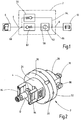
- the schematic representation of the Fig. 1 illustrates the arrangement in a process to be carried out in the course of a refueling process, in which the device housing 2 is connected with its inlet 4 to a source for hydrogen under high pressure in the form of an H 2 filling station 6 and the housing 2 with its outlet 8 is connected to a vehicle 10 to be refueled is in connection.
- the housing 2 has a tank nipple 12 at the inlet 4 a screw-in part seated in an internally threaded bore 14 at the inlet 4.
- a connecting pipe 18 is screwed to the internal thread in a bore 16, which can be connected to a tank hose, also not shown, on which a fuel nozzle for refueling the vehicle 10 is located.
- the housing 2 made of stainless steel has two housing parts, each of which has a circular cylindrical flange part 20 and 22, which have the same diameter and are adjoined by coaxial connection parts 24 and 26, of which the connection part 24 has the bore at the free end 14 of the inlet 4 and the connection part 26 has the bore 16 of the inlet 8 at the outer end.
- the connection parts 24, 26 are largely in the form of circular cylinders with a reduced diameter compared to the flange parts 20, 22 with flattened areas lying opposite one another, see FIG Fig. 2 . When the housing 2 is closed, the flange parts 20 and 22 abut one another at end faces 28 and 30 which lie in a radial plane.
- a union nut 32 is provided, which is rotatable on an external thread 34 of the flange part 22 and has an annular part 36 that extends over the other flange part 20.
- the union nut 32 has bores 38 located radially on the outside. The union nut 32 can be secured in the tightened position by means of a spring-loaded locking bolt 40 which passes through the ring part 36.
- the end surface 30 has a concentric, axially projecting annular rib 42 which fits into an annular groove 44 in the other end surface 30, with a sealing ring 46 in an extension the annular groove 44 is used.
- coaxial depressions 48 and 50 are formed in the flange parts 20 and 22 and delimit a sample chamber 52.
- the recesses 48, 50 are each formed by a cone with a right-angled apex, a coaxial inflow channel 54 opening out at the apex of the recess 48, which is connected to the tank nipple 12 via the inlet 4.
- An outflow channel 56 extends from the apex of the other recess 50 via the outlet 8 to the connection pipe 18.
- a test filter 58 in the form of a leaf-shaped, circular membrane. It may be laminated with a support structure for a paper filter with a filtration rating in the range of 0.2 ⁇ m or a PTFD membrane. Such filters can have a thickness of 0.15 mm.
- a support filter 60 in the form of a circular plate is provided as a holder, on whose side facing the inflow channel 54 the test filter 58 rests.
- the thickness of the plate of the support filter 60 is 5 mm in the present example, and the support filter 60 is formed from a sintered metal with a porosity which corresponds to a filter fineness in the range of 150 ⁇ m.
- the plate of the support filter 60 is held between the annular rib 42 of the end face 28 and the base of the annular groove 44 in the end face 30.
- a first valve in the form of a spring-loaded check valve 62 which opens in the direction of the sample chamber 52, is located in the end region of the inlet line 54 which opens into the sample chamber 52.
- a connecting line 64 (see Sect. Fig. 3 ) is provided, which opens with its one end into a connection point 66 between test filter 58 and outlet 8, and with its other end opens into a connection point 68 between inlet 4 and the check valve 62 forming the first valve.
- a Second valve is arranged, which is also designed as a spring-loaded check valve 70 and opens in the direction of the connection point 68 and thus in the direction of the outlet 4.
- Both check valves 62 and 70 are designed as built-in check valves in the so-called cartridge design, all of their components being made of stainless steel.
- bores 72 and 74 which form the ends of the connecting line 64, are closed by threaded plugs 76 and 78.
- the transition of the connecting line 64 at the separation point formed between the end faces 28 and 30 is formed by a connecting pipe 80 which is sealed in the respective flange part 20, 22 by sealing elements 82.
- grip strips 84 are provided on the housing 2 on the end face of the connection part 24 next to the tank nipple 12.
- the tank nipple 12 is connected to the filling coupling of the H 2 filling station 6, and a tank hose with a filling nozzle is attached to the connecting pipe 18.
- Conventional hose rupture safeguards present on the tank hose can be secured to the housing 2 by means of retaining bolts 86 which protrude laterally from the connection part 24 and can be suspended in the retaining eyelets.
- the first check valve 62 opens so that the flow through the test filter 58. Closing the filling nozzle at the end of the refueling process activates the ventilation system of the filling station 6.
- the hydrogen pressure in the sample chamber 52 and in the tank hose connected to the outlet 8 closes the first check valve 62 and opens the second check valve 70 in the connecting line 64, so that this serves as a vent valve, via which the pressure reduction to the outlet 4 and thereby to the venting system of the petrol station 6 takes place.
- the test device can now be used without manual venting via a drain valve can be uncoupled and opened in a laboratory in order to analyze deposits on the test filter 58.
Landscapes
- Engineering & Computer Science (AREA)
- Health & Medical Sciences (AREA)
- Life Sciences & Earth Sciences (AREA)
- Chemical & Material Sciences (AREA)
- Immunology (AREA)
- General Physics & Mathematics (AREA)
- Pathology (AREA)
- General Engineering & Computer Science (AREA)
- Analytical Chemistry (AREA)
- Biochemistry (AREA)
- General Health & Medical Sciences (AREA)
- Physics & Mathematics (AREA)
- Mechanical Engineering (AREA)
- Dispersion Chemistry (AREA)
- Biomedical Technology (AREA)
- Molecular Biology (AREA)
- Filling Or Discharging Of Gas Storage Vessels (AREA)
- Sampling And Sample Adjustment (AREA)
- Cooling, Air Intake And Gas Exhaust, And Fuel Tank Arrangements In Propulsion Units (AREA)
Description
- Die Erfindung betrifft eine Prüfvorrichtung zum Ermitteln der Partikelbelastung von unter einem hohen Druck stehendem Wasserstoff, mit einem Gehäuse, das einen Einlass und einen Auslass für das Einströmen des Wasserstoffs bzw. das Ausströmen desselben sowie eine Probenkammer aufweist, in der eine Filteraufnahme für einen Prüffilter vorgesehen ist, der bei einem Prüfvorgang von einer Probenmenge Wasserstoff durchströmbar und nach Ende des Prüfvorgangs aus der Probenkammer für die Auswertung der Anlagerung von Partikeln herausnehmbar ist, und mit einer einen Druckabbau der Probenkammer ermöglichenden Entlüftungseinrichtung.
- Eine Prüfvorrichtung dieser Art ist bekannt, s.
WO 2013/139462 A1 . Solche Vorrichtungen sind hauptsächlich für eine Anwendung bei Wasserstoff-Betankungssystemen benutzbar, also namentlich bei motorischen Anwendungen, bei denen Wasserstoff als gasförmiger Kraftstoff benutzt wird, oder für die Versorgung von Brennstoffzellen mit Wasserstoff. Bei mit Wasserstoff betriebenen Verbrennungsmotoren, ebenso wie bei Brennstoffzellen, ist es für den störungsfreien Betrieb ausschlaggebend, dass der Wasserstoff von partikulären Fremdstoffen völlig frei ist. Die Prüfung auf Partikelfreiheit leistet daher einen wichtigen Beitrag zur Gewährleistung eines sicheren Betriebs der mit Wasserstoff zu versorgenden Einrichtungen. - Bei der Benutzung der erwähnten, bekannten Prüfvorrichtung wird der Prüfvorgang im Zuge eines Betankungsvorgangs durchgeführt, bei dem der Einlass des Gehäuses der Prüfvorrichtung mit einer H2-Tankstelle in Verbindung gebracht ist und der Auslass über einen Tankschlauch mit einer Zapfpistole in Verbindung ist, beispielsweise für die Betankung eines Fahrzeugs. Während diesem Vorgang, bei dem über die Zapfpistole die Verbindung zum Tank des Verbrauchers hergestellt ist, ist der in der Probenkammer befindliche Prüffilter von der die Probenmenge bildenden Tankmenge durchströmt. Um nach Beendigung des Tankvorgangs den Prüffilter für die Untersuchung auf Anlagerungen entnehmen zu können, ist die unter dem hohen Betankungsdruck von 800 bar oder höher stehende Probenkammer drucklos zu machen. Hierfür ist bei der erwähnten, bekannten Prüfvorrichtung als Entlüftungseinrichtung ein an der Gehäuseaußenseite befindliches, manuell betätigbares Entlüftungsventil zu öffnen, das einen Ausgangsstutzen aufweist, über den das Gasvolumen zur Umgebung ausbläst, das sich in der Probenkammer sowie im Tankschlauch und in der Verbindung zur H2-Tankstelle befindet. Diese Verbindungen können nunmehr vom Einlass und vom Auslass des Gehäuses abgenommen werden, so dass das Gehäuse in ein Labor verbracht und geöffnet werden kann, um den Prüffilter auf Anlagerungen zu untersuchen und festgestellte Anlagerungen zu analysieren.
- Ausgehend von diesem Stand der Technik stellt sich die Erfindung die Aufgabe, eine Prüfvorrichtung der eingangs genannten Gattung zur Verfügung zu stellen, die sich durch ein besonders sicheres Betriebsverhalten auszeichnet.
- Erfindungsgemäß ist diese Aufgabe durch eine Prüfvorrichtung gelöst, die die Merkmale des Patentanspruchs 1 in seiner Gesamtheit aufweist.
- Gemäß dem kennzeichnenden Teil des Anspruchs 1 besteht eine wesentliche Besonderheit der Erfindung darin, dass die Entlüftungseinrichtung innerhalb des Gehäuses angeordnet und nach einer Beendigung des Ausströmens von Wasserstoff in der Prüfvorrichtung noch verbliebenen Wasserstoff, zumindest teilweise, in Richtung des Einlasses aus der Prüfvorrichtung abführt. Dadurch erfolgt bei Beendigung des Tankvorgangs der Entlüftungsvorgang automatisch über das Entlüftungssystem, das in den Tankstellen, die für die Hochdruck-Wasserstoffbetankung zugelassen sind, vorgesehen ist. Eine von Hand über ein Ablassventil durchzuführende Entlüftung, bei der in der Umgebung eine gefährliche Wasserstoffatmosphäre entstehen könnte, erübrigt sich daher.
- Bei vorteilhaften Ausführungsbeispielen weist die Entlüftungseinrichtung zwei Ventile auf, von denen das erste Ventil den Strömungsweg vom Einlass zum Auslass über den Prüffilter freigibt bei geschlossenem zweiten Ventil, das nach Beendigung des Ausströmens am Auslass unter dem Druck des in der Prüfvorrichtung zurückgebliebenen Wasserstoffs bei einem vorgebbaren Schwellenwert öffnet und dabei die Entlüftung in Richtung des Einlasses vornimmt bei geschlossenem ersten Ventil.
- Mit Vorteil können die beiden Ventile aus federbelasteten Rückschlagventilen gebildet sein, von denen das erste Ventil, ausgehend von seiner Schließstellung, in Richtung des Auslasses und das zweite Ventil entgegengesetzt in Richtung des Einlasses öffnet.
- Mit Vorteil ist die Anordnung derart getroffen, dass das zweite Ventil im Bypass zum ersten Ventil in einer Verbindungsleitung angeordnet ist, die mit ihrem einen Ende in eine Verbindungstelle zwischen Prüffilter und Auslass und mit ihrem anderen Ende in eine weitere Verbindungsstelle zwischen Einlass und dem ersten Ventil des Strömungswegs einmündet. Bei dieser Anordnung der Verbindungsleitung umgeht der Strömungsweg, der bei geöffnetem zweitem Ventil über die Verbindungsleitung verläuft, den Prüffilter, so dass über diesen kein unerwünschter Rückstrom stattfindet.
- Für die Durchführung eines Prüfvorgangs sind der Einlass fluidführend an einen Wasserstoff-Vorratstank, insbesondere bei einer Kraftfahrzeug-Tankstelle, und der Auslass über eine Schlauchleitung an eine Zapfpistole für die Wasserstoffabgabe an ein Fahrzeug anschließbar, so dass eine Entlüftung mittels der Entlüftungseinrichtung nach einem Tank- oder Entnahmevorgang durch ein Entlüftungssystem der Tankstelle automatisch erfolgt.
- Das Gehäuse ist bei bevorzugten Ausführungsbeispielen mehrteilig, insbesondere zweiteilig, ausgebildet, wobei die beiden Gehäuseteile mittels einer wieder lösbaren Überwurfmutter miteinander verbunden sind. Für diese kann eine Verdrehsicherung vorgesehen sein, die die Überwurfmutter in der angezogenen Drehstellung lösbar festlegt.
- Mit Vorteil können die beiden Ventile in Form von Einbau-Rückschlagventilen in das eine Gehäuseteil aufgenommen sein, das den Einlass aufweist.
- Der Prüffilter kann in vorteilhafter Weise zwischen den beiden Gehäuseteilen in der Probenkammer mit der Filteraufnahme festgelegt sein, wobei die Probenkammer an den beiden freien Stirnseiten des Prüffilters jeweils eine konische Erweiterung aufweist, die sich in entgegengesetzten Richtungen vom Prüffilter abgewandt verjüngen und in den Strömungsweg zwischen Einlass und Auslass einmünden.
- Zur Bildung eines abgedichteten Übergangs der das zweite Ventil enthaltenden Verbindungsleitung zwischen den beiden Gehäuseteilen kann mit Vorteil in der Verbindungsleitung und zwischen den beiden Gehäuseteilen angeordnet sowie in diese eingreifend ein Verbindungsrohr vorhanden sein, das mittels mindestens eines Dichtelements in abgedichteter Weise im jeweiligen Gehäuseteil geführt ist und die Trennstelle zwischen den beiden Gehäuseteilen durchgreift.
- Vorzugsweise sind die Bestandteile der Prüfvorrichtung, einschließlich der eingesetzten Ventile nebst ihren Dichtelementen, aus Edelstahl-Materialien gebildet.
- Nachstehend ist die Erfindung anhand eines in der Zeichnung dargestellten Ausführungsbeispiels im Einzelnen erläutert.
- Es zeigen:
- Fig. 1
- in Symboldarstellung die Fluidschaltung des Ausführungsbeispiels der erfindungsgemäßen Prüfvorrichtung, eingefügt zwischen einer H2-Tankstelle und einem zu betankenden Kraftfahrzeug;
- Fig. 2
- eine perspektivische Schrägansicht des Ausführungsbeispiels, gesehen auf den mit der Tankstelle zu verbindenden Einlass des Vorrichtungsgehäuses;
- Fig. 3
- einen Längsschnitt des Ausführungsbeispiels; und
- Fig. 4
- einen Längsschnitt des Ausführungsbeispiels mit gegenüber
Fig. 3 um 90° verdrehter Schnittebene. - Die schematische Darstellung der
Fig. 1 verdeutlicht die Anordnung bei einem im Zuge eines Betankungsvorgangs durchzuführenden Vorgang, bei dem das Vorrichtungsgehäuse 2 mit seinem Einlass 4 mit einer Quelle für unter hohem Druck stehendem Wasserstoff in Form einer H2-Tankstelle 6 in Verbindung ist und das Gehäuse 2 mit seinem Auslass 8 mit einem zu betankenden Fahrzeug 10 in Verbindung ist. Für die Verbindung mit der Tankstelle 6 weist das Gehäuse 2 am Einlass 4 einen Tanknippel 12 in Form eines in einer mit Innengewinde versehenen Bohrung 14 am Eingang 4 sitzenden Einschraubteils auf. Am gegenüberliegenden Auslass 8 ist mit dem Innengewinde in einer Bohrung 16 ein Anschlussrohr 18 verschraubt, das mit einem ebenfalls nicht gezeigten Tankschlauch verbindbar ist, an dem sich eine Zapfpistole zur Betankung des Fahrzeugs 10 befindet. - Das aus Edelstahl gefertigte Gehäuse 2 weist zwei Gehäuseteile auf, die jedes jeweils ein kreiszylindrisches Flanschteil 20 und 22 aufweisen, die den gleichen Durchmesser aufweisen und an die sich jeweils koaxiale Anschlussteile 24 bzw. 26 anschließen, von denen das Anschlussteil 24 am freien Ende die Bohrung 14 des Einlasses 4 aufweist und das Anschlussteil 26 am äußeren Ende die Bohrung 16 des Einlasses 8 aufweist. Die Anschlussteile 24, 26 haben im großen Ganzen die Form von im Durchmesser gegenüber den Flanschteilen 20, 22 verringerten Kreiszylindern mit einander gegenüberliegenden Abflachungen, siehe
Fig. 2 . Bei geschlossenem Gehäuse 2 liegen die Flanschteile 20 und 22 an Endflächen 28 und 30 aneinander, die in einer Radialebene liegen. Für die druckfeste und lösbare Aneinanderlage der Endflächen 28, 30 ist eine Überwurfmutter 32 vorgesehen, die auf einem Außengewinde 34 des Flanschteils 22 drehbar ist und ein das andere Flanschteil 20 übergreifendes Ringteil 36 aufweist. Zum Festziehen mittels eines Hakenschlüssels weist die Überwurfmutter 32 radial außenliegende Bohrungen 38 auf. Mittels eines federbelasteten, das Ringteil 36 durchgreifenden Sperrbolzens 40 ist die Überwurfmutter 32 in der festgezogenen Stellung sicherbar. - Für die Zentrierung und gegenseitige Abdichtung der aneinanderliegenden Endflächen 28 und 30 der Flanschteile 20, 22 weist die Endfläche 30 eine konzentrische, axial vorspringende Ringrippe 42 auf, die in eine Ringnut 44 in der anderen Endfläche 30 passend eingreift, wobei ein Dichtring 46 in eine Erweiterung der Ringnut 44 eingesetzt ist. In entsprechender Weise wie bei der erwähnten, aus
WO 2013/139462 A1 bekannten Prüfvorrichtung sind von den Endflächen 28 und 30 ausgehend in den Flanschteilen 20 und 22 koaxiale Vertiefungen 48 und 50 ausgebildet, die eine Probenkammer 52 begrenzen. Die Vertiefungen 48, 50 sind, wie bei der genannten, bekannten Vorrichtung, durch je einen Konus mit rechtwinkligem Scheitel gebildet, wobei am Scheitel der Vertiefung 48 ein koaxialer Zuströmkanal 54 einmündet, der über den Einlass 4 mit dem Tanknippel 12 in Verbindung ist. Vom Scheitel der anderen Vertiefung 50 erstreckt sich ein Abströmkanal 56 über den Auslass 8 zum Anschlussrohr 18. - In der Probenkammer 52 befindet sich ein Prüffilter 58 in Form einer blattförmigen, kreisrunden Membran. Dabei kann es sich um ein Papierfilter mit einer Filterfeinheit im Bereich von 0,2 µm oder um eine PTFD-Membran mit laminierter Stützstruktur handeln. Derartige Filter können eine Dicke von 0,15 mm aufweisen. Als Halterung für ein derartiges blattförmiges Element ist als Halterung ein Abstützfilter 60 in Form einer kreisrunden Platte vorgesehen, an deren dem Zuströmkanal 54 zugewandten Seite der Prüffilter 58 anliegt. Die Dicke der Platte des Abstützfilters 60 beträgt beim vorliegenden Beispiel 5 mm, und der Abstützfilter 60 ist aus einem Sintermetall mit einer Porosität gebildet, die einer Filterfeinheit im Bereich von 150 µm entspricht. Die Platte des Abstützfilters 60 ist zwischen der Ringrippe 42 der Endfläche 28 und dem Grund der Ringnut 44 in der Endfläche 30 gehalten.
- In dem in die Probenkammer 52 einmündenden Endbereich der Zulaufleitung 54 befindet sich ein erstes Ventil in Form eines federbelasteten Rückschlagventils 62, das in Richtung zur Probenkammer 52 öffnet. Als Bypass zum Rückschlagventil 62 ist eine Verbindungsleitung 64 (s.
Fig. 3 ) vorgesehen, die mit ihrem einen Ende in eine Verbindungsstelle 66 zwischen Prüffilter 58 und Auslass 8 einmündet, und mit ihrem anderen Ende in eine Verbindungsstelle 68 zwischen Einlass 4 und dem das erste Ventil bildenden Rückschlagventil 62 einmündet. In dieser Verbindungsleitung 64 ist ein zweites Ventil angeordnet, das ebenfalls als federbelastetes Rückschlagventil 70 ausgebildet ist und in Richtung auf die Verbindungsstelle 68 und damit in Richtung zum Auslass 4 öffnet. Beide Rückschlagventile 62 und 70 sind als Einbau-Rückschlagventile in der sog. Cartridge-Bauweise ausgebildet, wobei ihre sämtlichen Bestandteile aus Edelstahl bestehen. Wie dieFig. 3 zeigt, sind Bohrungen 72 und 74, die die Enden der Verbindungsleitung 64 bilden, durch Gewindestopfen 76 und 78 geschlossen. Wie ebenfallsFig. 3 zeigt, ist der Übergang der Verbindungsleitung 64 an der zwischen den Endflächen 28 und 30 gebildeten Trennstelle durch ein Verbindungsrohr 80 gebildet, das im jeweiligen Flanschteil 20, 22 durch Dichtelemente 82 abgedichtet ist. - Zur Erleichterung der Handhabung der Prüfvorrichtung zur Durchführung eines Betankungs- und Prüfvorgangs sind am Gehäuse 2 an der Stirnseite des Anschlussteils 24 neben dem Tanknippel 12 Griffleisten 84 vorgesehen. Für den während der Betankung des Fahrzeugs 10 stattfindenden Prüfvorgang wird der Tanknippel 12 an der Füllkupplung der H2-Tankstelle 6 angeschlossen, und am Anschlussrohr 18 wird ein Tankschlauch mit einer Zapfpistole angebracht. Dabei können am Tankschlauch vorhandene übliche Schlauchbruchsicherungen am Gehäuse 2 mittels Haltebolzen 86 gesichert werden, die vom Anschlussteil 24 seitlich vorstehen und in die Halteösen einhängbar sind. Bei dem nun durchgeführten Betankungsvorgang öffnet das erste Rückschlagventil 62, so dass der Prüffilter 58 durchströmt ist. Das Schließen der Zapfpistole am Ende des Betankungsvorgangs aktiviert das Entlüftungssystem der Tankstelle 6. Der in der Probenkammer 52 und im an den Auslass 8 angeschlossenen Tankschlauch herrschende Wasserstoffdruck schließt das erste Rückschlagventil 62 und öffnet das in der Verbindungsleitung 64 befindliche zweite Rückschlagventil 70, so dass dieses als Entlüftungsventil dient, über das der Druckabbau zum Auslass 4 und dadurch zum Entlüftungssystem der Tankstelle 6 hin erfolgt. Ohne dass eine manuelle Entlüftung über ein Ablassventil erfolgen müsste, kann nunmehr die Prüfvorrichtung abgekuppelt und in einem Labor geöffnet werden, um Ablagerungen auf dem Prüffilter 58 zu analysieren.
Claims (10)
- Prüfvorrichtung zum Ermitteln der Partikelbelastung von unter einem hohen Druck stehendem Wasserstoff, mit einem Gehäuse (2), das einen Einlass (4) und einen Auslass (8) für das Einströmen des Wasserstoffs bzw. das Ausströmen desselben sowie eine Probenkammer (52) aufweist, in der eine Filteraufnahme (44) für einen Prüffilter (58) vorgesehen ist, der bei einem Prüfvorgang von einer Probenmenge Wasserstoff durchströmbar und nach Ende des Prüfvorgangs aus der Probenkammer (52) für die Auswertung der Anlagerung von Partikeln herausnehmbar ist, und mit einer einen Druckabbau der Probenkammer (52) ermöglichenden Entlüftungseinrichtung (64, 70), dadurch gekennzeichnet, dass die Entlüftungseinrichtung (64, 70) innerhalb des Gehäuses (2) angeordnet ist und nach einer Beendigung des Ausströmens von Wasserstoff in der Prüfvorrichtung noch verbliebenen Wasserstoff, zumindest teilweise, in Richtung des Einlasses (4) aus der Prüfvorrichtung abführt.
- Prüfvorrichtung nach Anspruch 1, dadurch gekennzeichnet, dass die Entlüftungseinrichtung zwei Ventile (62, 70) aufweist, von denen das erste Ventil (62) den Strömungsweg vom Einlass (4) zum Auslass (8) über den Prüffilter (58) freigibt bei geschlossenem zweiten Ventil (70), das nach Beendigung des Ausströmens am Auslass (8) unter dem Druck des in der Prüfvorrichtung zurückgebliebenen Wasserstoffs bei einem vorgebbaren Schwellenwert öffnet und dabei die Entlüftung in Richtung des Einlasses (4) vornimmt bei geschlossenem erstem Ventil (62).
- Prüfvorrichtung nach Anspruch 1 oder 2, dadurch gekennzeichnet, dass die beiden Ventile aus federbelasteten Rückschlagventilen (62, 70) gebildet sind, von denen das erste Ventil (62), ausgehend von seiner Schließstellung, in Richtung des Auslasses (8) und das zweite Ventil (70) entgegengesetzt in Richtung des Einlasses (4) öffnet.
- Prüfvorrichtung nach einem der vorstehenden Ansprüche, dadurch gekennzeichnet, dass das zweite Ventil (70) im Bypass zum ersten Ventil (62) in einer Verbindungsleitung (64) angeordnet ist, die mit ihrem einen Ende in eine Verbindungsstelle (66) zwischen Prüffilter (58) und Auslass (8) und mit ihrem anderen Ende in eine weitere Verbindungsstelle (68) zwischen Einlass (4) und dem ersten Ventil (62) des Strömungsweges einmündet.
- Prüfvorrichtung nach einem der vorstehenden Ansprüche, dadurch gekennzeichnet, dass der Einlass (4) fluidführend an einen Wasserstoff-Vorratstank, insbesondere bei einer Kraftfahrzeug-Tankstelle (6), und der Auslass (8) über eine Schlauchleitung an eine Zapfpistole für die Wasserstoffabgabe an ein Fahrzeug (10) anschließbar sind und dass eine Entlüftung mittels der Entlüftungseinrichtung (64, 70) nach einem Tank- oder Entnahmevorgang durch ein Entlüftungssystem der Tankstelle (6) automatisch erfolgt.
- Prüfvorrichtung nach einem der vorstehenden Ansprüche, dadurch gekennzeichnet, dass das Gehäuse (2) mehrteilig, insbesondere zweiteilig, ausgebildet ist und dass die beiden Gehäuseteile (20, 22) mittels einer wieder lösbaren Überwurfmutter (32) miteinander verbunden sind.
- Prüfvorrichtung nach einem der vorstehenden Ansprüche, dadurch gekennzeichnet, dass die beiden Ventile in Form von Einbau-Rückschlagventilen (62, 70) in das eine Gehäuseteil (20) aufgenommen sind, das den Einlass (4) aufweist.
- Prüfvorrichtung nach einem der vorstehenden Ansprüche, dadurch gekennzeichnet, dass der Prüffilter (58) zwischen den beiden Gehäuseteilen (20, 22) in der Probenkammer (52) mit der Filteraufnahme (44) festgelegt ist und dass die Probenkammer (52) an den beiden freien Stirnseiten des Prüffilters jeweils eine konische Erweiterung (48, 50) aufweist, die sich in entgegengesetzten Richtungen vom Prüffilter (58) abgewandt verjüngen und in den Strömungsweg zwischen Einlass (4) und Auslass (8) einmünden.
- Prüfvorrichtung nach einem der vorstehenden Ansprüche, dadurch gekennzeichnet, dass in der Verbindungsleitung (64) und zwischen den beiden Gehäuseteilen (20, 22) angeordnet sowie in diese eingreifend ein Verbindungsrohr (80) vorhanden ist, das mittels mindestens eines Dichtelements (82) in abgedichteter Weise im jeweiligen Gehäuseteil (20, 22) geführt ist und die Trennstelle zwischen den beiden Gehäuseteilen (20, 22) durchgreift.
- Prüfvorrichtung nach einem der vorstehenden Ansprüche, dadurch gekennzeichnet, dass ihre Bestandteile, einschließlich der eingesetzten Ventile (62, 70) nebst ihren Dichtelementen, aus Edelstahl-Materialien gebildet sind.
Applications Claiming Priority (2)
| Application Number | Priority Date | Filing Date | Title |
|---|---|---|---|
| DE102017006063.0A DE102017006063A1 (de) | 2017-06-27 | 2017-06-27 | Prüfvorrichtung zum Ermitteln der Partikelbelastung von unter einem hohen Druck stehendem Wasserstoff |
| PCT/EP2018/067057 WO2019002260A1 (de) | 2017-06-27 | 2018-06-26 | Prüfvorrichtung zum ermitteln der partikelbelastung von unter einem hohen druck stehendem wasserstoff |
Publications (2)
| Publication Number | Publication Date |
|---|---|
| EP3646000A1 EP3646000A1 (de) | 2020-05-06 |
| EP3646000B1 true EP3646000B1 (de) | 2021-03-31 |
Family
ID=62750996
Family Applications (1)
| Application Number | Title | Priority Date | Filing Date |
|---|---|---|---|
| EP18734536.8A Active EP3646000B1 (de) | 2017-06-27 | 2018-06-26 | Prüfvorrichtung zum ermitteln der partikelbelastung von unter einem hohen druck stehendem wasserstoff |
Country Status (7)
| Country | Link |
|---|---|
| US (1) | US11408810B2 (de) |
| EP (1) | EP3646000B1 (de) |
| JP (1) | JP6867515B2 (de) |
| KR (1) | KR102324299B1 (de) |
| CN (1) | CN110678733B (de) |
| DE (1) | DE102017006063A1 (de) |
| WO (1) | WO2019002260A1 (de) |
Families Citing this family (3)
| Publication number | Priority date | Publication date | Assignee | Title |
|---|---|---|---|---|
| CN111504732A (zh) * | 2020-05-27 | 2020-08-07 | 佛山绿色发展创新研究院 | 一种高压气体颗粒物采样装置 |
| KR102508825B1 (ko) * | 2022-08-05 | 2023-03-10 | 엘제이솔루션 | 수소 충전소용 다이렉트 수소 연료 품질 분석기 |
| CN115939446B (zh) * | 2022-12-02 | 2025-05-13 | 国能氢创科技(北京)有限责任公司 | 一种用于移动实验室的燃料电池车 |
Family Cites Families (19)
| Publication number | Priority date | Publication date | Assignee | Title |
|---|---|---|---|---|
| US3015228A (en) * | 1955-09-12 | 1962-01-02 | Cornelius J Shuttleworth | Air quality gauge |
| GB1358102A (en) * | 1971-05-28 | 1974-06-26 | Saf Gard Products Inc | Method and apparatus for purging air from internal combustion engine |
| US5196170A (en) * | 1990-11-13 | 1993-03-23 | Rupprecht & Patashnick Company, Inc. | Carbon particulate monitor |
| DE4430471A1 (de) * | 1994-08-27 | 1996-02-29 | Bosch Gmbh Robert | Flüssigkeitsfilter mit eingebautem Druckregler |
| DE19736846A1 (de) * | 1997-08-23 | 1999-03-04 | Mannesmann Vdo Ag | Druckregelanordnung |
| DE19963388A1 (de) * | 1999-12-28 | 2001-07-05 | Bosch Gmbh Robert | Filtervorrichtung für ein Kraftstoffversorgungssystem einer Brennkraftmaschine eines Fahrzeugs |
| US7097925B2 (en) * | 2000-10-30 | 2006-08-29 | Questair Technologies Inc. | High temperature fuel cell power plant |
| WO2005018034A1 (en) | 2003-08-19 | 2005-02-24 | Hydrogenics Corporation | Method and system for distributing hydrogen |
| US7325561B2 (en) * | 2004-12-02 | 2008-02-05 | Honda Motor Co., Ltd. | Hydrogen vehicle gas utilization and refueling system |
| EP1688731A1 (de) * | 2005-02-03 | 2006-08-09 | Air Products and Chemicals, Inc. | Vorrichtung und Verfahren zur Messung und/oder Analyse von Teilchen in einem Gasstrom |
| KR100837973B1 (ko) | 2007-05-22 | 2008-06-13 | 현대자동차주식회사 | 미분말 필터링 구조를 갖는 수소저장합금 탱크 |
| US7631568B2 (en) * | 2007-08-28 | 2009-12-15 | Quest Technologies | Particulate monitor |
| NL2003427C2 (en) * | 2009-09-02 | 2011-03-03 | Parker Filtration B V | FILTER PACKAGE. |
| US8378535B2 (en) * | 2010-02-26 | 2013-02-19 | General Electric Company | Scavenging filter system for hydrogen-cooled dynamoelectric machines |
| CN102182916A (zh) * | 2011-02-11 | 2011-09-14 | 张家港富瑞特种装备股份有限公司 | 液化天然气加注机 |
| DE102012005719A1 (de) | 2012-03-20 | 2013-09-26 | Hydac Accessories Gmbh | Prüfvorrichtung zum Ermitteln der Partikelbelastung von unter einem hohen Druck stehendem Wasserstoff |
| FR3010482B1 (fr) * | 2013-09-12 | 2015-10-16 | Air Liquide | Dispositif d'echantillonnage de gaz et station de remplissage comprenant un tel dispositif |
| KR101514326B1 (ko) | 2013-10-23 | 2015-04-22 | 한국표준과학연구원 | 수소 투과량 측정 장치 및 방법 |
| JP6369075B2 (ja) * | 2014-03-20 | 2018-08-08 | 株式会社Ihi | 排気ガスサンプリング装置 |
-
2017
- 2017-06-27 DE DE102017006063.0A patent/DE102017006063A1/de not_active Withdrawn
-
2018
- 2018-06-26 US US16/623,867 patent/US11408810B2/en active Active
- 2018-06-26 JP JP2019567637A patent/JP6867515B2/ja active Active
- 2018-06-26 KR KR1020197037954A patent/KR102324299B1/ko active Active
- 2018-06-26 WO PCT/EP2018/067057 patent/WO2019002260A1/de not_active Ceased
- 2018-06-26 EP EP18734536.8A patent/EP3646000B1/de active Active
- 2018-06-26 CN CN201880035630.9A patent/CN110678733B/zh active Active
Non-Patent Citations (1)
| Title |
|---|
| None * |
Also Published As
| Publication number | Publication date |
|---|---|
| KR20200018789A (ko) | 2020-02-20 |
| CN110678733B (zh) | 2022-06-14 |
| KR102324299B1 (ko) | 2021-11-15 |
| JP2020525759A (ja) | 2020-08-27 |
| WO2019002260A1 (de) | 2019-01-03 |
| JP6867515B2 (ja) | 2021-04-28 |
| CN110678733A (zh) | 2020-01-10 |
| EP3646000A1 (de) | 2020-05-06 |
| US20200166447A1 (en) | 2020-05-28 |
| US11408810B2 (en) | 2022-08-09 |
| DE102017006063A1 (de) | 2018-12-27 |
Similar Documents
| Publication | Publication Date | Title |
|---|---|---|
| EP3479008B1 (de) | Tankventil | |
| DE102020201172A1 (de) | Vorrichtung zum Speichern von Druckgas, Fahrzeug | |
| EP3646000B1 (de) | Prüfvorrichtung zum ermitteln der partikelbelastung von unter einem hohen druck stehendem wasserstoff | |
| DE102016008079A1 (de) | Tankventil | |
| DE2639533C3 (de) | Druckprobe-Stopfen für eine Rohrleitung | |
| DE112016004523T5 (de) | Systeme und Verfahren zur Integration eines Druckdifferentsensors | |
| EP2333291A1 (de) | Kraftstofftank | |
| EP2828638B1 (de) | Prüfvorrichtung zum ermitteln der partikelbelastung von unter einem hohen druck stehendem wasserstoff | |
| DE69001352T2 (de) | Dichtendes Absperrventil. | |
| WO2020169763A1 (de) | Modulares ventilkörpersystem | |
| EP1950354B1 (de) | Systemtrenner | |
| EP3524871B1 (de) | Druckgasflasche mit gasentnahmeventil | |
| DE102016008106A1 (de) | Tankventil | |
| EP3999369A1 (de) | Ablaufstutzen zum getrennten auslassen von flüssigkeiten unterschiedlicher dichte | |
| WO2015128326A1 (de) | Druckreduzier-ventil für eine löschanlage sowie löschanlage mit einem derartigen druckreduzier-ventil | |
| DE112020000819T5 (de) | Schnüffelsonde und Lecksucher | |
| DE102014006029C5 (de) | Austragsystem | |
| DE102024107068A1 (de) | Systemtrennereinheit | |
| DE102022104637A1 (de) | Einleiten eines Fluids in einen Anschluss | |
| DE102022001144A1 (de) | Ausdehnungsvorrichtung | |
| DE3446095C1 (de) | Elektrodenhalter für Vielpunkt-Schweißmaschinen | |
| DE102022104641A1 (de) | Einleiten eines Fluids in einen Anschluss | |
| DE102022104638A1 (de) | Einleiten eines Fluids in einen Anschluss | |
| DE492113C (de) | Pruef- und Sicherheitsvorrichtung fuer das einem Filter zugefuehrte Schmieroel | |
| WO2017137388A1 (de) | Vorrichtung zur zentralen gasversorgung |
Legal Events
| Date | Code | Title | Description |
|---|---|---|---|
| STAA | Information on the status of an ep patent application or granted ep patent |
Free format text: STATUS: UNKNOWN |
|
| STAA | Information on the status of an ep patent application or granted ep patent |
Free format text: STATUS: THE INTERNATIONAL PUBLICATION HAS BEEN MADE |
|
| PUAI | Public reference made under article 153(3) epc to a published international application that has entered the european phase |
Free format text: ORIGINAL CODE: 0009012 |
|
| STAA | Information on the status of an ep patent application or granted ep patent |
Free format text: STATUS: REQUEST FOR EXAMINATION WAS MADE |
|
| 17P | Request for examination filed |
Effective date: 20200127 |
|
| AK | Designated contracting states |
Kind code of ref document: A1 Designated state(s): AL AT BE BG CH CY CZ DE DK EE ES FI FR GB GR HR HU IE IS IT LI LT LU LV MC MK MT NL NO PL PT RO RS SE SI SK SM TR |
|
| AX | Request for extension of the european patent |
Extension state: BA ME |
|
| DAV | Request for validation of the european patent (deleted) | ||
| DAX | Request for extension of the european patent (deleted) | ||
| GRAP | Despatch of communication of intention to grant a patent |
Free format text: ORIGINAL CODE: EPIDOSNIGR1 |
|
| STAA | Information on the status of an ep patent application or granted ep patent |
Free format text: STATUS: GRANT OF PATENT IS INTENDED |
|
| INTG | Intention to grant announced |
Effective date: 20201110 |
|
| GRAS | Grant fee paid |
Free format text: ORIGINAL CODE: EPIDOSNIGR3 |
|
| GRAA | (expected) grant |
Free format text: ORIGINAL CODE: 0009210 |
|
| STAA | Information on the status of an ep patent application or granted ep patent |
Free format text: STATUS: THE PATENT HAS BEEN GRANTED |
|
| AK | Designated contracting states |
Kind code of ref document: B1 Designated state(s): AL AT BE BG CH CY CZ DE DK EE ES FI FR GB GR HR HU IE IS IT LI LT LU LV MC MK MT NL NO PL PT RO RS SE SI SK SM TR |
|
| REG | Reference to a national code |
Ref country code: GB Ref legal event code: FG4D Free format text: NOT ENGLISH Ref country code: CH Ref legal event code: EP |
|
| REG | Reference to a national code |
Ref country code: DE Ref legal event code: R096 Ref document number: 502018004569 Country of ref document: DE Ref country code: AT Ref legal event code: REF Ref document number: 1377489 Country of ref document: AT Kind code of ref document: T Effective date: 20210415 |
|
| REG | Reference to a national code |
Ref country code: IE Ref legal event code: FG4D Free format text: LANGUAGE OF EP DOCUMENT: GERMAN |
|
| REG | Reference to a national code |
Ref country code: NL Ref legal event code: FP |
|
| REG | Reference to a national code |
Ref country code: LT Ref legal event code: MG9D |
|
| PG25 | Lapsed in a contracting state [announced via postgrant information from national office to epo] |
Ref country code: FI Free format text: LAPSE BECAUSE OF FAILURE TO SUBMIT A TRANSLATION OF THE DESCRIPTION OR TO PAY THE FEE WITHIN THE PRESCRIBED TIME-LIMIT Effective date: 20210331 Ref country code: HR Free format text: LAPSE BECAUSE OF FAILURE TO SUBMIT A TRANSLATION OF THE DESCRIPTION OR TO PAY THE FEE WITHIN THE PRESCRIBED TIME-LIMIT Effective date: 20210331 Ref country code: BG Free format text: LAPSE BECAUSE OF FAILURE TO SUBMIT A TRANSLATION OF THE DESCRIPTION OR TO PAY THE FEE WITHIN THE PRESCRIBED TIME-LIMIT Effective date: 20210630 Ref country code: NO Free format text: LAPSE BECAUSE OF FAILURE TO SUBMIT A TRANSLATION OF THE DESCRIPTION OR TO PAY THE FEE WITHIN THE PRESCRIBED TIME-LIMIT Effective date: 20210630 |
|
| PG25 | Lapsed in a contracting state [announced via postgrant information from national office to epo] |
Ref country code: SE Free format text: LAPSE BECAUSE OF FAILURE TO SUBMIT A TRANSLATION OF THE DESCRIPTION OR TO PAY THE FEE WITHIN THE PRESCRIBED TIME-LIMIT Effective date: 20210331 Ref country code: RS Free format text: LAPSE BECAUSE OF FAILURE TO SUBMIT A TRANSLATION OF THE DESCRIPTION OR TO PAY THE FEE WITHIN THE PRESCRIBED TIME-LIMIT Effective date: 20210331 Ref country code: LV Free format text: LAPSE BECAUSE OF FAILURE TO SUBMIT A TRANSLATION OF THE DESCRIPTION OR TO PAY THE FEE WITHIN THE PRESCRIBED TIME-LIMIT Effective date: 20210331 |
|
| PG25 | Lapsed in a contracting state [announced via postgrant information from national office to epo] |
Ref country code: LT Free format text: LAPSE BECAUSE OF FAILURE TO SUBMIT A TRANSLATION OF THE DESCRIPTION OR TO PAY THE FEE WITHIN THE PRESCRIBED TIME-LIMIT Effective date: 20210331 Ref country code: CZ Free format text: LAPSE BECAUSE OF FAILURE TO SUBMIT A TRANSLATION OF THE DESCRIPTION OR TO PAY THE FEE WITHIN THE PRESCRIBED TIME-LIMIT Effective date: 20210331 Ref country code: EE Free format text: LAPSE BECAUSE OF FAILURE TO SUBMIT A TRANSLATION OF THE DESCRIPTION OR TO PAY THE FEE WITHIN THE PRESCRIBED TIME-LIMIT Effective date: 20210331 Ref country code: SM Free format text: LAPSE BECAUSE OF FAILURE TO SUBMIT A TRANSLATION OF THE DESCRIPTION OR TO PAY THE FEE WITHIN THE PRESCRIBED TIME-LIMIT Effective date: 20210331 |
|
| PG25 | Lapsed in a contracting state [announced via postgrant information from national office to epo] |
Ref country code: SK Free format text: LAPSE BECAUSE OF FAILURE TO SUBMIT A TRANSLATION OF THE DESCRIPTION OR TO PAY THE FEE WITHIN THE PRESCRIBED TIME-LIMIT Effective date: 20210331 Ref country code: RO Free format text: LAPSE BECAUSE OF FAILURE TO SUBMIT A TRANSLATION OF THE DESCRIPTION OR TO PAY THE FEE WITHIN THE PRESCRIBED TIME-LIMIT Effective date: 20210331 Ref country code: PT Free format text: LAPSE BECAUSE OF FAILURE TO SUBMIT A TRANSLATION OF THE DESCRIPTION OR TO PAY THE FEE WITHIN THE PRESCRIBED TIME-LIMIT Effective date: 20210802 Ref country code: PL Free format text: LAPSE BECAUSE OF FAILURE TO SUBMIT A TRANSLATION OF THE DESCRIPTION OR TO PAY THE FEE WITHIN THE PRESCRIBED TIME-LIMIT Effective date: 20210331 Ref country code: IS Free format text: LAPSE BECAUSE OF FAILURE TO SUBMIT A TRANSLATION OF THE DESCRIPTION OR TO PAY THE FEE WITHIN THE PRESCRIBED TIME-LIMIT Effective date: 20210731 |
|
| REG | Reference to a national code |
Ref country code: DE Ref legal event code: R097 Ref document number: 502018004569 Country of ref document: DE |
|
| PG25 | Lapsed in a contracting state [announced via postgrant information from national office to epo] |
Ref country code: MC Free format text: LAPSE BECAUSE OF FAILURE TO SUBMIT A TRANSLATION OF THE DESCRIPTION OR TO PAY THE FEE WITHIN THE PRESCRIBED TIME-LIMIT Effective date: 20210331 Ref country code: AL Free format text: LAPSE BECAUSE OF FAILURE TO SUBMIT A TRANSLATION OF THE DESCRIPTION OR TO PAY THE FEE WITHIN THE PRESCRIBED TIME-LIMIT Effective date: 20210331 Ref country code: DK Free format text: LAPSE BECAUSE OF FAILURE TO SUBMIT A TRANSLATION OF THE DESCRIPTION OR TO PAY THE FEE WITHIN THE PRESCRIBED TIME-LIMIT Effective date: 20210331 Ref country code: ES Free format text: LAPSE BECAUSE OF FAILURE TO SUBMIT A TRANSLATION OF THE DESCRIPTION OR TO PAY THE FEE WITHIN THE PRESCRIBED TIME-LIMIT Effective date: 20210331 |
|
| REG | Reference to a national code |
Ref country code: CH Ref legal event code: PL |
|
| PLBE | No opposition filed within time limit |
Free format text: ORIGINAL CODE: 0009261 |
|
| STAA | Information on the status of an ep patent application or granted ep patent |
Free format text: STATUS: NO OPPOSITION FILED WITHIN TIME LIMIT |
|
| 26N | No opposition filed |
Effective date: 20220104 |
|
| REG | Reference to a national code |
Ref country code: BE Ref legal event code: MM Effective date: 20210630 |
|
| PG25 | Lapsed in a contracting state [announced via postgrant information from national office to epo] |
Ref country code: LU Free format text: LAPSE BECAUSE OF NON-PAYMENT OF DUE FEES Effective date: 20210626 |
|
| PG25 | Lapsed in a contracting state [announced via postgrant information from national office to epo] |
Ref country code: LI Free format text: LAPSE BECAUSE OF NON-PAYMENT OF DUE FEES Effective date: 20210630 Ref country code: IE Free format text: LAPSE BECAUSE OF NON-PAYMENT OF DUE FEES Effective date: 20210626 Ref country code: CH Free format text: LAPSE BECAUSE OF NON-PAYMENT OF DUE FEES Effective date: 20210630 |
|
| PG25 | Lapsed in a contracting state [announced via postgrant information from national office to epo] |
Ref country code: IS Free format text: LAPSE BECAUSE OF FAILURE TO SUBMIT A TRANSLATION OF THE DESCRIPTION OR TO PAY THE FEE WITHIN THE PRESCRIBED TIME-LIMIT Effective date: 20210731 |
|
| PG25 | Lapsed in a contracting state [announced via postgrant information from national office to epo] |
Ref country code: IT Free format text: LAPSE BECAUSE OF FAILURE TO SUBMIT A TRANSLATION OF THE DESCRIPTION OR TO PAY THE FEE WITHIN THE PRESCRIBED TIME-LIMIT Effective date: 20210331 Ref country code: BE Free format text: LAPSE BECAUSE OF NON-PAYMENT OF DUE FEES Effective date: 20210630 |
|
| PG25 | Lapsed in a contracting state [announced via postgrant information from national office to epo] |
Ref country code: CY Free format text: LAPSE BECAUSE OF FAILURE TO SUBMIT A TRANSLATION OF THE DESCRIPTION OR TO PAY THE FEE WITHIN THE PRESCRIBED TIME-LIMIT Effective date: 20210331 |
|
| PG25 | Lapsed in a contracting state [announced via postgrant information from national office to epo] |
Ref country code: HU Free format text: LAPSE BECAUSE OF FAILURE TO SUBMIT A TRANSLATION OF THE DESCRIPTION OR TO PAY THE FEE WITHIN THE PRESCRIBED TIME-LIMIT; INVALID AB INITIO Effective date: 20180626 Ref country code: GR Free format text: LAPSE BECAUSE OF FAILURE TO SUBMIT A TRANSLATION OF THE DESCRIPTION OR TO PAY THE FEE WITHIN THE PRESCRIBED TIME-LIMIT Effective date: 20210331 |
|
| PG25 | Lapsed in a contracting state [announced via postgrant information from national office to epo] |
Ref country code: MK Free format text: LAPSE BECAUSE OF FAILURE TO SUBMIT A TRANSLATION OF THE DESCRIPTION OR TO PAY THE FEE WITHIN THE PRESCRIBED TIME-LIMIT Effective date: 20210331 |
|
| REG | Reference to a national code |
Ref country code: AT Ref legal event code: MM01 Ref document number: 1377489 Country of ref document: AT Kind code of ref document: T Effective date: 20230626 |
|
| PG25 | Lapsed in a contracting state [announced via postgrant information from national office to epo] |
Ref country code: MT Free format text: LAPSE BECAUSE OF FAILURE TO SUBMIT A TRANSLATION OF THE DESCRIPTION OR TO PAY THE FEE WITHIN THE PRESCRIBED TIME-LIMIT Effective date: 20210331 |
|
| PG25 | Lapsed in a contracting state [announced via postgrant information from national office to epo] |
Ref country code: AT Free format text: LAPSE BECAUSE OF NON-PAYMENT OF DUE FEES Effective date: 20230626 |
|
| PG25 | Lapsed in a contracting state [announced via postgrant information from national office to epo] |
Ref country code: AT Free format text: LAPSE BECAUSE OF NON-PAYMENT OF DUE FEES Effective date: 20230626 |
|
| PGFP | Annual fee paid to national office [announced via postgrant information from national office to epo] |
Ref country code: DE Payment date: 20250630 Year of fee payment: 8 |
|
| PGFP | Annual fee paid to national office [announced via postgrant information from national office to epo] |
Ref country code: GB Payment date: 20250408 Year of fee payment: 8 |
|
| PGFP | Annual fee paid to national office [announced via postgrant information from national office to epo] |
Ref country code: NL Payment date: 20250623 Year of fee payment: 8 |
|
| PGFP | Annual fee paid to national office [announced via postgrant information from national office to epo] |
Ref country code: FR Payment date: 20250407 Year of fee payment: 8 |
|
| PG25 | Lapsed in a contracting state [announced via postgrant information from national office to epo] |
Ref country code: TR Free format text: LAPSE BECAUSE OF FAILURE TO SUBMIT A TRANSLATION OF THE DESCRIPTION OR TO PAY THE FEE WITHIN THE PRESCRIBED TIME-LIMIT Effective date: 20210331 |
|
| PGFP | Annual fee paid to national office [announced via postgrant information from national office to epo] |
Ref country code: AT Payment date: 20260410 Year of fee payment: 5 |