EP3646406B1 - Procédé de renforcement d'un poteau télescopique - Google Patents
Procédé de renforcement d'un poteau télescopique Download PDFInfo
- Publication number
- EP3646406B1 EP3646406B1 EP18824838.9A EP18824838A EP3646406B1 EP 3646406 B1 EP3646406 B1 EP 3646406B1 EP 18824838 A EP18824838 A EP 18824838A EP 3646406 B1 EP3646406 B1 EP 3646406B1
- Authority
- EP
- European Patent Office
- Prior art keywords
- canister
- stiffener members
- stealth
- splice plate
- pole
- Prior art date
- Legal status (The legal status is an assumption and is not a legal conclusion. Google has not performed a legal analysis and makes no representation as to the accuracy of the status listed.)
- Active
Links
Images


Classifications
-
- E—FIXED CONSTRUCTIONS
- E04—BUILDING
- E04H—BUILDINGS OR LIKE STRUCTURES FOR PARTICULAR PURPOSES; SWIMMING OR SPLASH BATHS OR POOLS; MASTS; FENCING; TENTS OR CANOPIES, IN GENERAL
- E04H12/00—Towers; Masts or poles; Chimney stacks; Water-towers; Methods of erecting such structures
- E04H12/16—Prestressed structures
-
- E—FIXED CONSTRUCTIONS
- E04—BUILDING
- E04H—BUILDINGS OR LIKE STRUCTURES FOR PARTICULAR PURPOSES; SWIMMING OR SPLASH BATHS OR POOLS; MASTS; FENCING; TENTS OR CANOPIES, IN GENERAL
- E04H12/00—Towers; Masts or poles; Chimney stacks; Water-towers; Methods of erecting such structures
- E04H12/003—Access covers or locks therefor
-
- E—FIXED CONSTRUCTIONS
- E04—BUILDING
- E04H—BUILDINGS OR LIKE STRUCTURES FOR PARTICULAR PURPOSES; SWIMMING OR SPLASH BATHS OR POOLS; MASTS; FENCING; TENTS OR CANOPIES, IN GENERAL
- E04H12/00—Towers; Masts or poles; Chimney stacks; Water-towers; Methods of erecting such structures
- E04H12/02—Structures made of specified materials
- E04H12/08—Structures made of specified materials of metal
- E04H12/085—Details of flanges for tubular masts
-
- H—ELECTRICITY
- H01—ELECTRIC ELEMENTS
- H01Q—ANTENNAS, i.e. RADIO AERIALS
- H01Q1/00—Details of, or arrangements associated with, antennas
- H01Q1/005—Damping of vibrations; Means for reducing wind-induced forces
-
- H—ELECTRICITY
- H01—ELECTRIC ELEMENTS
- H01Q—ANTENNAS, i.e. RADIO AERIALS
- H01Q1/00—Details of, or arrangements associated with, antennas
- H01Q1/12—Supports; Mounting means
- H01Q1/1207—Supports; Mounting means for fastening a rigid aerial element
- H01Q1/1228—Supports; Mounting means for fastening a rigid aerial element on a boom
-
- H—ELECTRICITY
- H01—ELECTRIC ELEMENTS
- H01Q—ANTENNAS, i.e. RADIO AERIALS
- H01Q1/00—Details of, or arrangements associated with, antennas
- H01Q1/12—Supports; Mounting means
- H01Q1/1242—Rigid masts specially adapted for supporting an aerial
-
- H—ELECTRICITY
- H01—ELECTRIC ELEMENTS
- H01Q—ANTENNAS, i.e. RADIO AERIALS
- H01Q1/00—Details of, or arrangements associated with, antennas
- H01Q1/12—Supports; Mounting means
- H01Q1/22—Supports; Mounting means by structural association with other equipment or articles
- H01Q1/24—Supports; Mounting means by structural association with other equipment or articles with receiving set
- H01Q1/241—Supports; Mounting means by structural association with other equipment or articles with receiving set used in mobile communications, e.g. GSM
- H01Q1/246—Supports; Mounting means by structural association with other equipment or articles with receiving set used in mobile communications, e.g. GSM specially adapted for base stations
-
- H—ELECTRICITY
- H01—ELECTRIC ELEMENTS
- H01Q—ANTENNAS, i.e. RADIO AERIALS
- H01Q1/00—Details of, or arrangements associated with, antennas
- H01Q1/42—Housings not intimately mechanically associated with radiating elements, e.g. radome
Definitions
- the present disclosure relates to telecommunications poles, and in particular to stealth poles that include a plurality of stiffener members that reinforce the stealth pole.
- US2005/0007295A1 describes an antenna tower and support structure for use with an antenna tower, which allow a number of antennas or antenna panels to be mounted thereto, while maintaining the compactness of the overall structure and still providing high strength, such as is needed to resist high winds.
- the antenna tower includes an antenna support structure mounted to the antenna mast for supporting one or more antennas or antenna panels.
- the antenna support structure includes a bottom plate for mounting to the mast (or to another antenna support structure) and a top plate spaced from bottom plate.
- a beam with multiple webs extends between the bottom plate and the top plate.
- the beam includes a central post and a number of stiffening webs extending generally radially outwardly from the central post. The stiffening webs help to provide substantially greater stiffness against flexure and bending, without making the overall structure larger (or not much larger effectively).
- EP1341255A1 describes an aerial module for attaching to a structure, in particular a lamp post, with a central column which has fastening devices for attaching transmitting and/or receiving aerials, in particular for telecommunications, and which is surrounded by a facing made from a material through which radio waves can permeate.
- the plurality of canister sections are adjacent each other on the stealth pole such that the first splice plate of a first canister section abuts a second splice plate of a second canister section at an interface between the first canister section and the second canister section, and the plurality of stiffener members extend through the first splice plate of the first canister section and the second splice plate of the second canister section such that the plurality of stiffener members reinforce the interface of the first canister section and the second canister section.
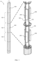
- the present disclosure relates to a stealth pole including a plurality of canister sections, each of the plurality of canister sections including a spine, a first splice plate located on a first end of the spine, a second splice plate located on a second end of the spine, and a canister cover that covers the spine, the first splice plate and the second splice plate.
- the terms “about” and “at or about” mean that the amount or value in question can be the designated value, approximately the designated value, or about the same as the designated value. It is generally understood, as used herein, that it is the nominal value indicated ⁇ 10% variation unless otherwise indicated or inferred. The term is intended to convey that similar values promote equivalent results or effects recited in the claims. That is, it is understood that amounts, sizes, formulations, parameters, and other quantities and characteristics are not and need not be exact, but can be approximate and/or larger or smaller, as desired, reflecting tolerances, conversion factors, rounding off, measurement error and the like, and other factors known to those of skill in the art.
- an amount, size, formulation, parameter or other quantity or characteristic is “about” or “approximate” whether or not expressly stated to be such. It is understood that where "about” is used before a quantitative value, the parameter also includes the specific quantitative value itself, unless specifically stated otherwise.
- the plurality of stiffener members 180 extend through two or more canister sections 100 so that a single stiffener member 180 reinforces a plurality of canister sections 100.
- the plurality of canister sections 100 are adjacent each other on the stealth pole 10 such that the first splice plate 140 of a first canister section 610 abuts a second splice plate 160 of a second canister section 620 at an interface between the first canister section 610 and the second canister section 620, and the plurality of stiffener members 180 extend through the first splice plate 140 of the first canister section 610 and the second splice plate 160 of the second canister section 620 such that the plurality of stiffener members 180 reinforce the interface of the first canister section 610 and the second canister section 620.
- a coupling 1000 may be included to connect stiffener members 180 where one stiffener member 180 ends and another stiffener member 180 begins.
- one or more of the plurality of stiffener members 180 are placed in tension, and one or more of the plurality of stiffener members 180 are also placed in compression. It may be desirable to place one or more stiffener members 180 that face a direction from which the wind predominantly blows into compression, and to place one or more stiffener members 180 that face a direction away from which the wind predominantly blows into tension.
- a canister section 100 includes three stiffener members 180, and in which the wind predominantly blows from the Southwest, two of the stiffener members 180 predominantly facing Southwest may be placed in compression and the one stiffener member predominantly facing Northeast may be placed in tension.
- the stiffener members 180 in compression will absorb some of the tension force applied to the stealth pole 10 (and become less compressed or even tensioned), and the stiffener member 180 in tension on the other side of the stealth pole 10 will become less tensioned or even compressed.
- the net result in the shift in tension/compression is that the overall stress on the spine 120 of the canister section 100 will be reduced.
- the method 300 described herein may be performed on the stealth pole 10 without removing the plurality of telecommunications antennas 250 from the stealth pole 10.
- the plurality of stiffener members 180 can be installed in the canister section 100 between the plurality of telecommunications antennas 250. This allows the method 300 to be performed without taking the plurality of telecommunications antennas 250 offline, saving the Carriers time and money. Further, the method 300 may be performed without the use of a welding process. This reduces the substantial risk of equipment damage and fire due to the presence of cables in the stealth pole.
Landscapes
- Engineering & Computer Science (AREA)
- Architecture (AREA)
- Civil Engineering (AREA)
- Structural Engineering (AREA)
- Chemical & Material Sciences (AREA)
- Life Sciences & Earth Sciences (AREA)
- Computer Networks & Wireless Communication (AREA)
- Materials Engineering (AREA)
- Wood Science & Technology (AREA)
- Working Measures On Existing Buildindgs (AREA)
- Wind Motors (AREA)
- Support Of Aerials (AREA)
- Electric Cable Installation (AREA)
Claims (11)
- Procédé de renforcement d'un poteau discret (10), le poteau discret (10) comprenant une pluralité de sections boîte (100), chaque section boîte de la pluralité de sections boîte comprenant un support (120), une première plaque de jointure (140) située sur une première extrémité du support, une seconde plaque de jointure (160) située sur une seconde extrémité du support, et un premier couvercle de boîte (200) qui couvre le support (120), la première plaque de jointure (140) et la seconde plaque de jointure (160), caractérisé en ce que le procédé comprend :le retrait du premier couvercle de boîte (200) d'au moins une section boîte de la pluralité de sections boîte (100) ;la fixation d'une pluralité d'éléments raidisseurs (180) à la première plaque de jointure (140) et à la seconde plaque de jointure (160) ; etl'application d'une tension, d'une compression ou d'une combinaison de celles-ci à la pluralité d'éléments raidisseurs (180),dans lequel la pluralité d'éléments raidisseurs (180) renforce le support (120) de la section boîte.
- Procédé selon la revendication 1, dans lequel au moins une des sections boîte (100) comprend une pluralité d'antennes de télécommunications (250) qui envoient ou reçoivent des signaux de communication sans fil, et le procédé est exécuté sur le poteau discret (10) sans mettre hors ligne la pluralité d'antennes de télécommunications (250).
- Procédé selon l'une quelconque des revendications 1 à 2, dans lequel l'étape de fixation de la pluralité d'éléments raidisseurs (180) à la première plaque de jointure (140) et à la seconde plaque de jointure (160) est réalisée sans procédé de soudage.
- Procédé selon l'une quelconque des revendications 1 à 3, dans lequel la pluralité d'éléments raidisseurs (180) comprend un matériau transparent aux radiofréquences (RF).
- Poteau discret (10), comprenant :une pluralité de sections boîte (100), chaque section boîte de la pluralité de sections boîte comprenant un support (120), une première plaque de jointure (140) située sur une première extrémité du support, une seconde plaque de jointure (160) située sur une seconde extrémité du support ; etune pluralité d'éléments raidisseurs (180) fixés à la première plaque de jointure (140) et à la seconde plaque de jointure (160) ;dans lequel la pluralité d'éléments raidisseurs (180) est en tension, en compression ou une combinaison de celles-ci, et la pluralité d'éléments raidisseurs (180) renforce le support (120),caractérisé en ce que les multiples sections boîte (100) sont adjacentes les unes aux autres sur le poteau discret (10) de telle sorte que la première plaque de jointure (140) d'une première section boîte (610) vienne en butée contre une seconde plaque de jointure (160) d'une seconde section boîte (620) au niveau d'une interface entre la première section boîte (610) et la seconde section boîte (620), et la pluralité d'éléments raidisseurs (180) s'étend à travers la première plaque de jointure (140) de la première section boîte (610) et la seconde plaque de jointure (160) de la seconde section boîte (620) de telle sorte que la pluralité d'éléments raidisseurs (180) renforce l'interface de la première section boîte (610) et de la seconde section boîte (620).
- Procédé selon la revendication 1 ou 2, ou poteau discret selon la revendication 5, dans lequel la pluralité d'éléments raidisseurs (180) comprend une tige, un fil, une corde en fibre polymère à haute ténacité, une barre ou une combinaison de ceux-ci.
- Procédé selon l'une quelconque des revendications 1, 2, 3 et 6, ou poteau discret selon l'une quelconque des revendications 5 à 6, dans lequel une tension est appliquée à un ou plusieurs éléments de la pluralité d'éléments raidisseurs (180), chaque élément de la pluralité d'éléments raidisseurs (180) a une capacité de tension maximale, et la tension appliquée à un ou plusieurs éléments de la pluralité d'éléments raidisseurs (180) est d'environ 1 % à environ 5 % de la capacité de tension maximale.
- Procédé selon l'une quelconque des revendications 1, 2, 3, 6 et 7, ou poteau discret selon l'une quelconque des revendications 5 à 7, dans lequel une compression est appliquée à un ou plusieurs éléments de la pluralité d'éléments raidisseurs (180), chaque élément de la pluralité d'éléments raidisseurs a une capacité de compression maximale, et la compression appliquée à un ou plusieurs éléments de la pluralité d'éléments raidisseurs (180) est d'environ 1 % à environ 5 % de la capacité de compression maximale.
- Procédé selon la revendication 8, ou poteau discret selon la revendication 8, dans lequel une combinaison de tension et de compression est appliquée à la pluralité d'éléments raidisseurs (180).
- Procédé selon l'une quelconque des revendications 1, 2, 3, 4, 6, 7, 8 et 9, ou poteau discret selon l'une quelconque des revendications 5 à 9, dans lequel au moins une des sections boîte (100) comprend une pluralité d'antennes de télécommunications (250) qui envoient ou reçoivent des signaux de communication sans fil, et la pluralité d'éléments raidisseurs (180) est située à l'intérieur de la section boîte (100) entre la pluralité d'antennes de télécommunications (250) de telle sorte qu'elle soit décalée par rapport à la pluralité d'antennes de télécommunications (250), et ne la recouvre pas.
- Procédé selon l'une quelconque des revendications 1, 2, 3, 4, 6, 7, 8, 9 et 10, comprenant en outre :la réinstallation du premier couvercle de boîte (200) autour de l'au moins une section boîte de la pluralité de sections boîte (100) ; oul'installation d'un second couvercle de boîte autour d'au moins une section boîte de la pluralité de sections boîte (100),dans lequel le second couvercle de boîte est différent du premier couvercle de boîte (200).
Applications Claiming Priority (3)
| Application Number | Priority Date | Filing Date | Title |
|---|---|---|---|
| US201762524954P | 2017-06-26 | 2017-06-26 | |
| US201762608729P | 2017-12-21 | 2017-12-21 | |
| PCT/US2018/027894 WO2019005267A1 (fr) | 2017-06-26 | 2018-04-17 | Procédés de renforcement d'un poteau télescopique |
Publications (4)
| Publication Number | Publication Date |
|---|---|
| EP3646406A1 EP3646406A1 (fr) | 2020-05-06 |
| EP3646406A4 EP3646406A4 (fr) | 2021-03-10 |
| EP3646406C0 EP3646406C0 (fr) | 2023-10-25 |
| EP3646406B1 true EP3646406B1 (fr) | 2023-10-25 |
Family
ID=64692038
Family Applications (1)
| Application Number | Title | Priority Date | Filing Date |
|---|---|---|---|
| EP18824838.9A Active EP3646406B1 (fr) | 2017-06-26 | 2018-04-17 | Procédé de renforcement d'un poteau télescopique |
Country Status (6)
| Country | Link |
|---|---|
| US (1) | US11359399B2 (fr) |
| EP (1) | EP3646406B1 (fr) |
| BR (1) | BR112019027512A2 (fr) |
| CA (1) | CA3068432A1 (fr) |
| MX (1) | MX2019015683A (fr) |
| WO (1) | WO2019005267A1 (fr) |
Families Citing this family (7)
| Publication number | Priority date | Publication date | Assignee | Title |
|---|---|---|---|---|
| US11359399B2 (en) * | 2017-06-26 | 2022-06-14 | Tower Engineering Solutions, Llc | Methods for reinforcing a stealth pole |
| DE102018131443A1 (de) * | 2018-12-07 | 2020-06-10 | Wobben Properties Gmbh | Fundamentanordnung, Adapterelement, Spannvorrichtung und Turm einer Windenergieanlage sowie Verfahren zum Vorspannen eines Turms einer Windenergieanlage |
| JP7135974B2 (ja) * | 2019-03-28 | 2022-09-13 | トヨタ自動車株式会社 | 支柱 |
| RU2743477C1 (ru) * | 2020-02-26 | 2021-02-18 | Федеральное Государственное Бюджетное Образовательное Учреждение Высшего Образования "Сибирский Государственный Университет Водного Транспорта" (Фгбоу Во "Сгувт") | Опора для воздушной линии электропередачи |
| WO2021206824A1 (fr) * | 2020-04-07 | 2021-10-14 | Commscope Technologies Llc | Module destiné à un poteau de télécommunication |
| US12098561B2 (en) * | 2020-10-28 | 2024-09-24 | Innovatech Systems, Llc | Temporary brace system for a structure |
| JP2025527199A (ja) * | 2022-06-29 | 2025-08-20 | ドミンゲス,エディ,イー. | 炭素繊維ポール建設のためのシステム及び方法 |
Family Cites Families (28)
| Publication number | Priority date | Publication date | Assignee | Title |
|---|---|---|---|---|
| US1786631A (en) * | 1928-04-25 | 1930-12-30 | Stephen W Borden | Supporting pole for electrical conductors |
| US3571991A (en) * | 1969-02-06 | 1971-03-23 | Anderson Electric Corp | Metal pole |
| SU750032A1 (ru) * | 1978-03-21 | 1980-07-23 | Грузинский научно-исследовательский институт энергетики и гидротехнических сооружений | Сборна башенна конструкци |
| US5266738A (en) * | 1991-10-25 | 1993-11-30 | United Lighting Standards, Inc. | Universal fixture mount and method of assembly |
| US5333436A (en) * | 1992-09-14 | 1994-08-02 | Pirod, Inc. | Modular antenna pole |
| US5687537A (en) * | 1996-05-24 | 1997-11-18 | Pi Rod Inc. | Modular antenna pole |
| US5995063A (en) * | 1998-08-13 | 1999-11-30 | Nortel Networks Corporation | Antenna structure |
| US6705058B1 (en) * | 1999-02-12 | 2004-03-16 | Newmark International Inc. | Multiple-part pole |
| US6658797B2 (en) * | 2001-01-31 | 2003-12-09 | Absolute Stealth Ltd. | Antenna support structure with palm tree skirt |
| US6901717B2 (en) | 2001-05-16 | 2005-06-07 | Pennsummit Tubular, Llc | Pole reinforcing arrangement |
| ATE298936T1 (de) * | 2002-02-25 | 2005-07-15 | Ewo Gmbh | Antennenmodul und lichtmast mit einem solchen antennenmodul |
| US6694698B2 (en) * | 2002-05-03 | 2004-02-24 | Creative Design & Maching, Inc. | Reinforcement apparatus for monopole towers |
| US20040139665A1 (en) * | 2003-03-07 | 2004-07-22 | Ray Ullrich | Method and arrangement for utility pole reinforcement |
| US6915618B2 (en) * | 2003-04-01 | 2005-07-12 | Spectrasite Communications, Inc. | Tower monopole reinforcement |
| US6982680B2 (en) | 2003-07-08 | 2006-01-03 | Ems Technologies, Inc. | Antenna tower and support structure therefor |
| WO2006094229A2 (fr) * | 2005-03-02 | 2006-09-08 | Bci Wireless Llc | Systemes et procedes pour le renforcement de structure a poteau unique |
| WO2007002147A2 (fr) * | 2005-06-21 | 2007-01-04 | Tim Jones | Systeme de renforcement de tours et equivalent |
| EP2207943B1 (fr) * | 2007-10-09 | 2016-11-23 | Jeffrey O. Willis | Structure de tour et procédé d'assemblage |
| US8749449B2 (en) * | 2009-09-14 | 2014-06-10 | Towerco Staffing, Inc. | Methods of modifying erect concealed antenna towers and associated modified towers and devices therefor |
| US20110140447A1 (en) * | 2010-11-10 | 2011-06-16 | Ingo Paura | Reinforcement assembly for use with a support tower of a wind turbine |
| ES2525405T3 (es) * | 2011-01-24 | 2014-12-22 | Alstom Renewable Technologies | Procedimiento para montar elementos de torre para formar secciones de una torre híbrida de un aerogenerador |
| EP2780977A1 (fr) * | 2011-11-18 | 2014-09-24 | Telefonaktiebolaget LM Ericsson (Publ) | Procédé et agencements ayant trait à un mât d'antenne d'un système de communication sans fil |
| US9153853B2 (en) | 2012-08-24 | 2015-10-06 | Wake Skykeeper, Llc | Monopole tower reinforcement configuration and related methods |
| EP2767654B1 (fr) * | 2013-02-19 | 2015-07-29 | Siemens Aktiengesellschaft | Assistant de bride servant à raccorder des sections de tour adjacentes |
| KR101340625B1 (ko) | 2013-06-18 | 2013-12-11 | (주)누리일렉콤 | 조립식 강관주 보강장치 |
| US9447580B2 (en) * | 2014-03-11 | 2016-09-20 | Bay Insulation Systems, Inc. | Covered flange brace and flange brace cover |
| MX395363B (es) * | 2015-08-31 | 2025-03-25 | Siemens Gamesa Renewable Energy Inc | Segmento de torre y metodo que utiliza placa segmentada de soporte. |
| US11359399B2 (en) * | 2017-06-26 | 2022-06-14 | Tower Engineering Solutions, Llc | Methods for reinforcing a stealth pole |
-
2018
- 2018-04-17 US US15/954,985 patent/US11359399B2/en active Active
- 2018-04-17 BR BR112019027512-6A patent/BR112019027512A2/pt unknown
- 2018-04-17 MX MX2019015683A patent/MX2019015683A/es unknown
- 2018-04-17 WO PCT/US2018/027894 patent/WO2019005267A1/fr not_active Ceased
- 2018-04-17 CA CA3068432A patent/CA3068432A1/fr active Pending
- 2018-04-17 EP EP18824838.9A patent/EP3646406B1/fr active Active
Also Published As
| Publication number | Publication date |
|---|---|
| MX2019015683A (es) | 2020-08-03 |
| EP3646406A1 (fr) | 2020-05-06 |
| BR112019027512A2 (pt) | 2020-07-07 |
| WO2019005267A1 (fr) | 2019-01-03 |
| US11359399B2 (en) | 2022-06-14 |
| EP3646406A4 (fr) | 2021-03-10 |
| EP3646406C0 (fr) | 2023-10-25 |
| US20180371783A1 (en) | 2018-12-27 |
| CA3068432A1 (fr) | 2019-01-03 |
Similar Documents
| Publication | Publication Date | Title |
|---|---|---|
| EP3646406B1 (fr) | Procédé de renforcement d'un poteau télescopique | |
| CN101410581B (zh) | 模块天线塔结构 | |
| EP1561947B1 (fr) | Pale d'éolienne transportable à troncons | |
| US20060028391A1 (en) | Antenna tower and support structure therefor | |
| JP2000509230A (ja) | アンテナシステム | |
| US12362467B2 (en) | Small cell installation structure | |
| WO2017196809A1 (fr) | Terminaison d'ancrage direct destinée à un renforcement de poteau | |
| Nielsen | Analysis and design of masts and towers | |
| SMITH | 50 years in the design of towers and masts. From IASS recommendations to current procedures | |
| US7609224B2 (en) | Reducing wind loads on monopoles to provide increased capacity without structural reinforcement | |
| DE20218101U1 (de) | Verkleideter Antennenträger | |
| Nielsen | The analysis of masts and towers | |
| Filipe et al. | Impact of geometrical and environmental parameters on wind action in telecommunication monopoles | |
| CN223190140U (zh) | 具有底部加强结构的远程通信塔 | |
| Støttrup‐Andersen et al. | 18.02: Optimisation of masts and towers | |
| CN218508475U (zh) | 一种信号发射塔的地基结构 | |
| CN220439882U (zh) | 一种用于天线单元安装的天线罩 | |
| CN220797072U (zh) | 一种多点定位天线屋面板安装装置 | |
| CN216042990U (zh) | 一种5g通信网络通讯塔 | |
| CN216957528U (zh) | 一种高强度抗拉耐腐蚀网络线缆 | |
| CN210838101U (zh) | 一种天线保护外罩 | |
| CN208267514U (zh) | 一种通信拉线塔用加固防护套 | |
| CN114497971A (zh) | 一种电子通讯天线用的固定设备及其固定方法 | |
| KR20030059044A (ko) | 수직 안테나와 레디얼의 결속방법 | |
| US20050109531A1 (en) | Polymer post insulator apparatus |
Legal Events
| Date | Code | Title | Description |
|---|---|---|---|
| STAA | Information on the status of an ep patent application or granted ep patent |
Free format text: STATUS: THE INTERNATIONAL PUBLICATION HAS BEEN MADE |
|
| PUAI | Public reference made under article 153(3) epc to a published international application that has entered the european phase |
Free format text: ORIGINAL CODE: 0009012 |
|
| STAA | Information on the status of an ep patent application or granted ep patent |
Free format text: STATUS: REQUEST FOR EXAMINATION WAS MADE |
|
| 17P | Request for examination filed |
Effective date: 20200115 |
|
| AK | Designated contracting states |
Kind code of ref document: A1 Designated state(s): AL AT BE BG CH CY CZ DE DK EE ES FI FR GB GR HR HU IE IS IT LI LT LU LV MC MK MT NL NO PL PT RO RS SE SI SK SM TR |
|
| AX | Request for extension of the european patent |
Extension state: BA ME |
|
| DAV | Request for validation of the european patent (deleted) | ||
| DAX | Request for extension of the european patent (deleted) | ||
| A4 | Supplementary search report drawn up and despatched |
Effective date: 20210209 |
|
| RIC1 | Information provided on ipc code assigned before grant |
Ipc: E02D 27/42 20060101ALI20210203BHEP Ipc: H01Q 1/24 20060101ALI20210203BHEP Ipc: E04H 12/22 20060101ALI20210203BHEP Ipc: H01Q 1/42 20060101ALI20210203BHEP Ipc: E04H 12/00 20060101ALI20210203BHEP Ipc: E04H 12/16 20060101ALI20210203BHEP Ipc: H01Q 1/00 20060101ALI20210203BHEP Ipc: E04H 12/08 20060101ALI20210203BHEP Ipc: H01Q 1/12 20060101AFI20210203BHEP |
|
| RIC1 | Information provided on ipc code assigned before grant |
Ipc: H01Q 1/42 20060101ALI20221024BHEP Ipc: H01Q 1/24 20060101ALI20221024BHEP Ipc: H01Q 1/00 20060101ALI20221024BHEP Ipc: E04H 12/16 20060101ALI20221024BHEP Ipc: E04H 12/08 20060101ALI20221024BHEP Ipc: E04H 12/00 20060101ALI20221024BHEP Ipc: E04H 12/22 20060101ALI20221024BHEP Ipc: E02D 27/42 20060101ALI20221024BHEP Ipc: H01Q 1/12 20060101AFI20221024BHEP |
|
| GRAP | Despatch of communication of intention to grant a patent |
Free format text: ORIGINAL CODE: EPIDOSNIGR1 |
|
| STAA | Information on the status of an ep patent application or granted ep patent |
Free format text: STATUS: GRANT OF PATENT IS INTENDED |
|
| INTG | Intention to grant announced |
Effective date: 20221207 |
|
| RIN1 | Information on inventor provided before grant (corrected) |
Inventor name: YOU, HANMING Inventor name: REYES, JAIME Inventor name: SEMAAN, ROBERT |
|
| GRAJ | Information related to disapproval of communication of intention to grant by the applicant or resumption of examination proceedings by the epo deleted |
Free format text: ORIGINAL CODE: EPIDOSDIGR1 |
|
| STAA | Information on the status of an ep patent application or granted ep patent |
Free format text: STATUS: REQUEST FOR EXAMINATION WAS MADE |
|
| GRAS | Grant fee paid |
Free format text: ORIGINAL CODE: EPIDOSNIGR3 |
|
| STAA | Information on the status of an ep patent application or granted ep patent |
Free format text: STATUS: GRANT OF PATENT IS INTENDED |
|
| GRAP | Despatch of communication of intention to grant a patent |
Free format text: ORIGINAL CODE: EPIDOSNIGR1 |
|
| INTC | Intention to grant announced (deleted) | ||
| INTG | Intention to grant announced |
Effective date: 20230508 |
|
| GRAF | Information related to payment of grant fee modified |
Free format text: ORIGINAL CODE: EPIDOSCIGR3 |
|
| GRAA | (expected) grant |
Free format text: ORIGINAL CODE: 0009210 |
|
| STAA | Information on the status of an ep patent application or granted ep patent |
Free format text: STATUS: THE PATENT HAS BEEN GRANTED |
|
| AK | Designated contracting states |
Kind code of ref document: B1 Designated state(s): AL AT BE BG CH CY CZ DE DK EE ES FI FR GB GR HR HU IE IS IT LI LT LU LV MC MK MT NL NO PL PT RO RS SE SI SK SM TR |
|
| REG | Reference to a national code |
Ref country code: GB Ref legal event code: FG4D |
|
| REG | Reference to a national code |
Ref country code: CH Ref legal event code: EP |
|
| REG | Reference to a national code |
Ref country code: DE Ref legal event code: R096 Ref document number: 602018060084 Country of ref document: DE |
|
| REG | Reference to a national code |
Ref country code: IE Ref legal event code: FG4D |
|
| U01 | Request for unitary effect filed |
Effective date: 20231121 |
|
| U07 | Unitary effect registered |
Designated state(s): AT BE BG DE DK EE FI FR IT LT LU LV MT NL PT SE SI Effective date: 20231128 |
|
| PG25 | Lapsed in a contracting state [announced via postgrant information from national office to epo] |
Ref country code: GR Free format text: LAPSE BECAUSE OF FAILURE TO SUBMIT A TRANSLATION OF THE DESCRIPTION OR TO PAY THE FEE WITHIN THE PRESCRIBED TIME-LIMIT Effective date: 20240126 |
|
| PG25 | Lapsed in a contracting state [announced via postgrant information from national office to epo] |
Ref country code: IS Free format text: LAPSE BECAUSE OF FAILURE TO SUBMIT A TRANSLATION OF THE DESCRIPTION OR TO PAY THE FEE WITHIN THE PRESCRIBED TIME-LIMIT Effective date: 20240225 |
|
| U20 | Renewal fee for the european patent with unitary effect paid |
Year of fee payment: 7 Effective date: 20240304 |
|
| PG25 | Lapsed in a contracting state [announced via postgrant information from national office to epo] |
Ref country code: ES Free format text: LAPSE BECAUSE OF FAILURE TO SUBMIT A TRANSLATION OF THE DESCRIPTION OR TO PAY THE FEE WITHIN THE PRESCRIBED TIME-LIMIT Effective date: 20231025 |
|
| PG25 | Lapsed in a contracting state [announced via postgrant information from national office to epo] |
Ref country code: IS Free format text: LAPSE BECAUSE OF FAILURE TO SUBMIT A TRANSLATION OF THE DESCRIPTION OR TO PAY THE FEE WITHIN THE PRESCRIBED TIME-LIMIT Effective date: 20240225 Ref country code: GR Free format text: LAPSE BECAUSE OF FAILURE TO SUBMIT A TRANSLATION OF THE DESCRIPTION OR TO PAY THE FEE WITHIN THE PRESCRIBED TIME-LIMIT Effective date: 20240126 Ref country code: ES Free format text: LAPSE BECAUSE OF FAILURE TO SUBMIT A TRANSLATION OF THE DESCRIPTION OR TO PAY THE FEE WITHIN THE PRESCRIBED TIME-LIMIT Effective date: 20231025 |
|
| PG25 | Lapsed in a contracting state [announced via postgrant information from national office to epo] |
Ref country code: RS Free format text: LAPSE BECAUSE OF FAILURE TO SUBMIT A TRANSLATION OF THE DESCRIPTION OR TO PAY THE FEE WITHIN THE PRESCRIBED TIME-LIMIT Effective date: 20231025 Ref country code: PL Free format text: LAPSE BECAUSE OF FAILURE TO SUBMIT A TRANSLATION OF THE DESCRIPTION OR TO PAY THE FEE WITHIN THE PRESCRIBED TIME-LIMIT Effective date: 20231025 Ref country code: NO Free format text: LAPSE BECAUSE OF FAILURE TO SUBMIT A TRANSLATION OF THE DESCRIPTION OR TO PAY THE FEE WITHIN THE PRESCRIBED TIME-LIMIT Effective date: 20240125 Ref country code: HR Free format text: LAPSE BECAUSE OF FAILURE TO SUBMIT A TRANSLATION OF THE DESCRIPTION OR TO PAY THE FEE WITHIN THE PRESCRIBED TIME-LIMIT Effective date: 20231025 |
|
| PG25 | Lapsed in a contracting state [announced via postgrant information from national office to epo] |
Ref country code: CZ Free format text: LAPSE BECAUSE OF FAILURE TO SUBMIT A TRANSLATION OF THE DESCRIPTION OR TO PAY THE FEE WITHIN THE PRESCRIBED TIME-LIMIT Effective date: 20231025 |
|
| REG | Reference to a national code |
Ref country code: DE Ref legal event code: R097 Ref document number: 602018060084 Country of ref document: DE |
|
| PG25 | Lapsed in a contracting state [announced via postgrant information from national office to epo] |
Ref country code: SK Free format text: LAPSE BECAUSE OF FAILURE TO SUBMIT A TRANSLATION OF THE DESCRIPTION OR TO PAY THE FEE WITHIN THE PRESCRIBED TIME-LIMIT Effective date: 20231025 |
|
| PG25 | Lapsed in a contracting state [announced via postgrant information from national office to epo] |
Ref country code: SM Free format text: LAPSE BECAUSE OF FAILURE TO SUBMIT A TRANSLATION OF THE DESCRIPTION OR TO PAY THE FEE WITHIN THE PRESCRIBED TIME-LIMIT Effective date: 20231025 Ref country code: SK Free format text: LAPSE BECAUSE OF FAILURE TO SUBMIT A TRANSLATION OF THE DESCRIPTION OR TO PAY THE FEE WITHIN THE PRESCRIBED TIME-LIMIT Effective date: 20231025 Ref country code: RO Free format text: LAPSE BECAUSE OF FAILURE TO SUBMIT A TRANSLATION OF THE DESCRIPTION OR TO PAY THE FEE WITHIN THE PRESCRIBED TIME-LIMIT Effective date: 20231025 Ref country code: CZ Free format text: LAPSE BECAUSE OF FAILURE TO SUBMIT A TRANSLATION OF THE DESCRIPTION OR TO PAY THE FEE WITHIN THE PRESCRIBED TIME-LIMIT Effective date: 20231025 |
|
| PLBE | No opposition filed within time limit |
Free format text: ORIGINAL CODE: 0009261 |
|
| STAA | Information on the status of an ep patent application or granted ep patent |
Free format text: STATUS: NO OPPOSITION FILED WITHIN TIME LIMIT |
|
| 26N | No opposition filed |
Effective date: 20240726 |
|
| PG25 | Lapsed in a contracting state [announced via postgrant information from national office to epo] |
Ref country code: MC Free format text: LAPSE BECAUSE OF FAILURE TO SUBMIT A TRANSLATION OF THE DESCRIPTION OR TO PAY THE FEE WITHIN THE PRESCRIBED TIME-LIMIT Effective date: 20231025 |
|
| PG25 | Lapsed in a contracting state [announced via postgrant information from national office to epo] |
Ref country code: MC Free format text: LAPSE BECAUSE OF FAILURE TO SUBMIT A TRANSLATION OF THE DESCRIPTION OR TO PAY THE FEE WITHIN THE PRESCRIBED TIME-LIMIT Effective date: 20231025 |
|
| REG | Reference to a national code |
Ref country code: CH Ref legal event code: PL |
|
| GBPC | Gb: european patent ceased through non-payment of renewal fee |
Effective date: 20240417 |
|
| PG25 | Lapsed in a contracting state [announced via postgrant information from national office to epo] |
Ref country code: GB Free format text: LAPSE BECAUSE OF NON-PAYMENT OF DUE FEES Effective date: 20240417 |
|
| PG25 | Lapsed in a contracting state [announced via postgrant information from national office to epo] |
Ref country code: GB Free format text: LAPSE BECAUSE OF NON-PAYMENT OF DUE FEES Effective date: 20240417 Ref country code: CH Free format text: LAPSE BECAUSE OF NON-PAYMENT OF DUE FEES Effective date: 20240430 |
|
| PG25 | Lapsed in a contracting state [announced via postgrant information from national office to epo] |
Ref country code: IE Free format text: LAPSE BECAUSE OF NON-PAYMENT OF DUE FEES Effective date: 20240417 |
|
| U20 | Renewal fee for the european patent with unitary effect paid |
Year of fee payment: 8 Effective date: 20250425 |
|
| PG25 | Lapsed in a contracting state [announced via postgrant information from national office to epo] |
Ref country code: CY Free format text: LAPSE BECAUSE OF FAILURE TO SUBMIT A TRANSLATION OF THE DESCRIPTION OR TO PAY THE FEE WITHIN THE PRESCRIBED TIME-LIMIT; INVALID AB INITIO Effective date: 20180417 |
|
| PG25 | Lapsed in a contracting state [announced via postgrant information from national office to epo] |
Ref country code: HU Free format text: LAPSE BECAUSE OF FAILURE TO SUBMIT A TRANSLATION OF THE DESCRIPTION OR TO PAY THE FEE WITHIN THE PRESCRIBED TIME-LIMIT; INVALID AB INITIO Effective date: 20180417 |
|
| U20 | Renewal fee for the european patent with unitary effect paid |
Year of fee payment: 9 Effective date: 20260310 |