EP3646843B1 - Vorrichtung zur unterstützung der körperbewegung - Google Patents
Vorrichtung zur unterstützung der körperbewegung Download PDFInfo
- Publication number
- EP3646843B1 EP3646843B1 EP18823136.9A EP18823136A EP3646843B1 EP 3646843 B1 EP3646843 B1 EP 3646843B1 EP 18823136 A EP18823136 A EP 18823136A EP 3646843 B1 EP3646843 B1 EP 3646843B1
- Authority
- EP
- European Patent Office
- Prior art keywords
- strap
- unit
- tension
- patient
- driving unit
- Prior art date
- Legal status (The legal status is an assumption and is not a legal conclusion. Google has not performed a legal analysis and makes no representation as to the accuracy of the status listed.)
- Active
Links
Images



Classifications
-
- A—HUMAN NECESSITIES
- A61—MEDICAL OR VETERINARY SCIENCE; HYGIENE
- A61H—PHYSICAL THERAPY APPARATUS, e.g. DEVICES FOR LOCATING OR STIMULATING REFLEX POINTS IN THE BODY; ARTIFICIAL RESPIRATION; MASSAGE; BATHING DEVICES FOR SPECIAL THERAPEUTIC OR HYGIENIC PURPOSES OR SPECIFIC PARTS OF THE BODY
- A61H1/00—Apparatus for passive exercising; Vibrating apparatus; Chiropractic devices, e.g. body impacting devices, external devices for briefly extending or aligning unbroken bones
- A61H1/02—Stretching or bending or torsioning apparatus for exercising
- A61H1/0274—Stretching or bending or torsioning apparatus for exercising for the upper limbs
-
- A—HUMAN NECESSITIES
- A61—MEDICAL OR VETERINARY SCIENCE; HYGIENE
- A61H—PHYSICAL THERAPY APPARATUS, e.g. DEVICES FOR LOCATING OR STIMULATING REFLEX POINTS IN THE BODY; ARTIFICIAL RESPIRATION; MASSAGE; BATHING DEVICES FOR SPECIAL THERAPEUTIC OR HYGIENIC PURPOSES OR SPECIFIC PARTS OF THE BODY
- A61H1/00—Apparatus for passive exercising; Vibrating apparatus; Chiropractic devices, e.g. body impacting devices, external devices for briefly extending or aligning unbroken bones
-
- A—HUMAN NECESSITIES
- A61—MEDICAL OR VETERINARY SCIENCE; HYGIENE
- A61H—PHYSICAL THERAPY APPARATUS, e.g. DEVICES FOR LOCATING OR STIMULATING REFLEX POINTS IN THE BODY; ARTIFICIAL RESPIRATION; MASSAGE; BATHING DEVICES FOR SPECIAL THERAPEUTIC OR HYGIENIC PURPOSES OR SPECIFIC PARTS OF THE BODY
- A61H1/00—Apparatus for passive exercising; Vibrating apparatus; Chiropractic devices, e.g. body impacting devices, external devices for briefly extending or aligning unbroken bones
- A61H1/02—Stretching or bending or torsioning apparatus for exercising
-
- A—HUMAN NECESSITIES
- A61—MEDICAL OR VETERINARY SCIENCE; HYGIENE
- A61H—PHYSICAL THERAPY APPARATUS, e.g. DEVICES FOR LOCATING OR STIMULATING REFLEX POINTS IN THE BODY; ARTIFICIAL RESPIRATION; MASSAGE; BATHING DEVICES FOR SPECIAL THERAPEUTIC OR HYGIENIC PURPOSES OR SPECIFIC PARTS OF THE BODY
- A61H1/00—Apparatus for passive exercising; Vibrating apparatus; Chiropractic devices, e.g. body impacting devices, external devices for briefly extending or aligning unbroken bones
- A61H1/02—Stretching or bending or torsioning apparatus for exercising
- A61H1/0274—Stretching or bending or torsioning apparatus for exercising for the upper limbs
- A61H1/0277—Elbow
-
- A—HUMAN NECESSITIES
- A61—MEDICAL OR VETERINARY SCIENCE; HYGIENE
- A61H—PHYSICAL THERAPY APPARATUS, e.g. DEVICES FOR LOCATING OR STIMULATING REFLEX POINTS IN THE BODY; ARTIFICIAL RESPIRATION; MASSAGE; BATHING DEVICES FOR SPECIAL THERAPEUTIC OR HYGIENIC PURPOSES OR SPECIFIC PARTS OF THE BODY
- A61H1/00—Apparatus for passive exercising; Vibrating apparatus; Chiropractic devices, e.g. body impacting devices, external devices for briefly extending or aligning unbroken bones
- A61H1/02—Stretching or bending or torsioning apparatus for exercising
- A61H1/0274—Stretching or bending or torsioning apparatus for exercising for the upper limbs
- A61H1/0285—Hand
-
- A—HUMAN NECESSITIES
- A61—MEDICAL OR VETERINARY SCIENCE; HYGIENE
- A61H—PHYSICAL THERAPY APPARATUS, e.g. DEVICES FOR LOCATING OR STIMULATING REFLEX POINTS IN THE BODY; ARTIFICIAL RESPIRATION; MASSAGE; BATHING DEVICES FOR SPECIAL THERAPEUTIC OR HYGIENIC PURPOSES OR SPECIFIC PARTS OF THE BODY
- A61H1/00—Apparatus for passive exercising; Vibrating apparatus; Chiropractic devices, e.g. body impacting devices, external devices for briefly extending or aligning unbroken bones
- A61H1/02—Stretching or bending or torsioning apparatus for exercising
- A61H1/0274—Stretching or bending or torsioning apparatus for exercising for the upper limbs
- A61H1/0285—Hand
- A61H1/0288—Fingers
-
- A—HUMAN NECESSITIES
- A61—MEDICAL OR VETERINARY SCIENCE; HYGIENE
- A61H—PHYSICAL THERAPY APPARATUS, e.g. DEVICES FOR LOCATING OR STIMULATING REFLEX POINTS IN THE BODY; ARTIFICIAL RESPIRATION; MASSAGE; BATHING DEVICES FOR SPECIAL THERAPEUTIC OR HYGIENIC PURPOSES OR SPECIFIC PARTS OF THE BODY
- A61H1/00—Apparatus for passive exercising; Vibrating apparatus; Chiropractic devices, e.g. body impacting devices, external devices for briefly extending or aligning unbroken bones
- A61H1/02—Stretching or bending or torsioning apparatus for exercising
- A61H2001/0203—Rotation of a body part around its longitudinal axis
-
- A—HUMAN NECESSITIES
- A61—MEDICAL OR VETERINARY SCIENCE; HYGIENE
- A61H—PHYSICAL THERAPY APPARATUS, e.g. DEVICES FOR LOCATING OR STIMULATING REFLEX POINTS IN THE BODY; ARTIFICIAL RESPIRATION; MASSAGE; BATHING DEVICES FOR SPECIAL THERAPEUTIC OR HYGIENIC PURPOSES OR SPECIFIC PARTS OF THE BODY
- A61H1/00—Apparatus for passive exercising; Vibrating apparatus; Chiropractic devices, e.g. body impacting devices, external devices for briefly extending or aligning unbroken bones
- A61H1/02—Stretching or bending or torsioning apparatus for exercising
- A61H2001/0207—Nutating movement of a body part around its articulation
-
- A—HUMAN NECESSITIES
- A61—MEDICAL OR VETERINARY SCIENCE; HYGIENE
- A61H—PHYSICAL THERAPY APPARATUS, e.g. DEVICES FOR LOCATING OR STIMULATING REFLEX POINTS IN THE BODY; ARTIFICIAL RESPIRATION; MASSAGE; BATHING DEVICES FOR SPECIAL THERAPEUTIC OR HYGIENIC PURPOSES OR SPECIFIC PARTS OF THE BODY
- A61H2201/00—Characteristics of apparatus not provided for in the preceding codes
- A61H2201/01—Constructive details
- A61H2201/0192—Specific means for adjusting dimensions
-
- A—HUMAN NECESSITIES
- A61—MEDICAL OR VETERINARY SCIENCE; HYGIENE
- A61H—PHYSICAL THERAPY APPARATUS, e.g. DEVICES FOR LOCATING OR STIMULATING REFLEX POINTS IN THE BODY; ARTIFICIAL RESPIRATION; MASSAGE; BATHING DEVICES FOR SPECIAL THERAPEUTIC OR HYGIENIC PURPOSES OR SPECIFIC PARTS OF THE BODY
- A61H2201/00—Characteristics of apparatus not provided for in the preceding codes
- A61H2201/12—Driving means
- A61H2201/1207—Driving means with electric or magnetic drive
- A61H2201/1215—Rotary drive
-
- A—HUMAN NECESSITIES
- A61—MEDICAL OR VETERINARY SCIENCE; HYGIENE
- A61H—PHYSICAL THERAPY APPARATUS, e.g. DEVICES FOR LOCATING OR STIMULATING REFLEX POINTS IN THE BODY; ARTIFICIAL RESPIRATION; MASSAGE; BATHING DEVICES FOR SPECIAL THERAPEUTIC OR HYGIENIC PURPOSES OR SPECIFIC PARTS OF THE BODY
- A61H2201/00—Characteristics of apparatus not provided for in the preceding codes
- A61H2201/14—Special force transmission means, i.e. between the driving means and the interface with the user
-
- A—HUMAN NECESSITIES
- A61—MEDICAL OR VETERINARY SCIENCE; HYGIENE
- A61H—PHYSICAL THERAPY APPARATUS, e.g. DEVICES FOR LOCATING OR STIMULATING REFLEX POINTS IN THE BODY; ARTIFICIAL RESPIRATION; MASSAGE; BATHING DEVICES FOR SPECIAL THERAPEUTIC OR HYGIENIC PURPOSES OR SPECIFIC PARTS OF THE BODY
- A61H2201/00—Characteristics of apparatus not provided for in the preceding codes
- A61H2201/16—Physical interface with patient
- A61H2201/1602—Physical interface with patient kind of interface, e.g. head rest, knee support or lumbar support
- A61H2201/1635—Hand or arm, e.g. handle
-
- A—HUMAN NECESSITIES
- A61—MEDICAL OR VETERINARY SCIENCE; HYGIENE
- A61H—PHYSICAL THERAPY APPARATUS, e.g. DEVICES FOR LOCATING OR STIMULATING REFLEX POINTS IN THE BODY; ARTIFICIAL RESPIRATION; MASSAGE; BATHING DEVICES FOR SPECIAL THERAPEUTIC OR HYGIENIC PURPOSES OR SPECIFIC PARTS OF THE BODY
- A61H2201/00—Characteristics of apparatus not provided for in the preceding codes
- A61H2201/16—Physical interface with patient
- A61H2201/1602—Physical interface with patient kind of interface, e.g. head rest, knee support or lumbar support
- A61H2201/1635—Hand or arm, e.g. handle
- A61H2201/1638—Holding means therefor
-
- A—HUMAN NECESSITIES
- A61—MEDICAL OR VETERINARY SCIENCE; HYGIENE
- A61H—PHYSICAL THERAPY APPARATUS, e.g. DEVICES FOR LOCATING OR STIMULATING REFLEX POINTS IN THE BODY; ARTIFICIAL RESPIRATION; MASSAGE; BATHING DEVICES FOR SPECIAL THERAPEUTIC OR HYGIENIC PURPOSES OR SPECIFIC PARTS OF THE BODY
- A61H2201/00—Characteristics of apparatus not provided for in the preceding codes
- A61H2201/16—Physical interface with patient
- A61H2201/1602—Physical interface with patient kind of interface, e.g. head rest, knee support or lumbar support
- A61H2201/165—Wearable interfaces
-
- A—HUMAN NECESSITIES
- A61—MEDICAL OR VETERINARY SCIENCE; HYGIENE
- A61H—PHYSICAL THERAPY APPARATUS, e.g. DEVICES FOR LOCATING OR STIMULATING REFLEX POINTS IN THE BODY; ARTIFICIAL RESPIRATION; MASSAGE; BATHING DEVICES FOR SPECIAL THERAPEUTIC OR HYGIENIC PURPOSES OR SPECIFIC PARTS OF THE BODY
- A61H2201/00—Characteristics of apparatus not provided for in the preceding codes
- A61H2201/16—Physical interface with patient
- A61H2201/1657—Movement of interface, i.e. force application means
- A61H2201/1671—Movement of interface, i.e. force application means rotational
-
- A—HUMAN NECESSITIES
- A61—MEDICAL OR VETERINARY SCIENCE; HYGIENE
- A61H—PHYSICAL THERAPY APPARATUS, e.g. DEVICES FOR LOCATING OR STIMULATING REFLEX POINTS IN THE BODY; ARTIFICIAL RESPIRATION; MASSAGE; BATHING DEVICES FOR SPECIAL THERAPEUTIC OR HYGIENIC PURPOSES OR SPECIFIC PARTS OF THE BODY
- A61H2201/00—Characteristics of apparatus not provided for in the preceding codes
- A61H2201/16—Physical interface with patient
- A61H2201/1657—Movement of interface, i.e. force application means
- A61H2201/1676—Pivoting
-
- A—HUMAN NECESSITIES
- A61—MEDICAL OR VETERINARY SCIENCE; HYGIENE
- A61H—PHYSICAL THERAPY APPARATUS, e.g. DEVICES FOR LOCATING OR STIMULATING REFLEX POINTS IN THE BODY; ARTIFICIAL RESPIRATION; MASSAGE; BATHING DEVICES FOR SPECIAL THERAPEUTIC OR HYGIENIC PURPOSES OR SPECIFIC PARTS OF THE BODY
- A61H2201/00—Characteristics of apparatus not provided for in the preceding codes
- A61H2201/16—Physical interface with patient
- A61H2201/1683—Surface of interface
- A61H2201/169—Physical characteristics of the surface, e.g. material, relief, texture or indicia
-
- A—HUMAN NECESSITIES
- A61—MEDICAL OR VETERINARY SCIENCE; HYGIENE
- A61H—PHYSICAL THERAPY APPARATUS, e.g. DEVICES FOR LOCATING OR STIMULATING REFLEX POINTS IN THE BODY; ARTIFICIAL RESPIRATION; MASSAGE; BATHING DEVICES FOR SPECIAL THERAPEUTIC OR HYGIENIC PURPOSES OR SPECIFIC PARTS OF THE BODY
- A61H2201/00—Characteristics of apparatus not provided for in the preceding codes
- A61H2201/50—Control means thereof
-
- A—HUMAN NECESSITIES
- A61—MEDICAL OR VETERINARY SCIENCE; HYGIENE
- A61H—PHYSICAL THERAPY APPARATUS, e.g. DEVICES FOR LOCATING OR STIMULATING REFLEX POINTS IN THE BODY; ARTIFICIAL RESPIRATION; MASSAGE; BATHING DEVICES FOR SPECIAL THERAPEUTIC OR HYGIENIC PURPOSES OR SPECIFIC PARTS OF THE BODY
- A61H2201/00—Characteristics of apparatus not provided for in the preceding codes
- A61H2201/50—Control means thereof
- A61H2201/5023—Interfaces to the user
- A61H2201/5043—Displays
-
- A—HUMAN NECESSITIES
- A61—MEDICAL OR VETERINARY SCIENCE; HYGIENE
- A61H—PHYSICAL THERAPY APPARATUS, e.g. DEVICES FOR LOCATING OR STIMULATING REFLEX POINTS IN THE BODY; ARTIFICIAL RESPIRATION; MASSAGE; BATHING DEVICES FOR SPECIAL THERAPEUTIC OR HYGIENIC PURPOSES OR SPECIFIC PARTS OF THE BODY
- A61H2201/00—Characteristics of apparatus not provided for in the preceding codes
- A61H2201/50—Control means thereof
- A61H2201/5058—Sensors or detectors
- A61H2201/5061—Force sensors
-
- A—HUMAN NECESSITIES
- A61—MEDICAL OR VETERINARY SCIENCE; HYGIENE
- A61H—PHYSICAL THERAPY APPARATUS, e.g. DEVICES FOR LOCATING OR STIMULATING REFLEX POINTS IN THE BODY; ARTIFICIAL RESPIRATION; MASSAGE; BATHING DEVICES FOR SPECIAL THERAPEUTIC OR HYGIENIC PURPOSES OR SPECIFIC PARTS OF THE BODY
- A61H2201/00—Characteristics of apparatus not provided for in the preceding codes
- A61H2201/50—Control means thereof
- A61H2201/5058—Sensors or detectors
- A61H2201/5064—Position sensors
-
- A—HUMAN NECESSITIES
- A61—MEDICAL OR VETERINARY SCIENCE; HYGIENE
- A61H—PHYSICAL THERAPY APPARATUS, e.g. DEVICES FOR LOCATING OR STIMULATING REFLEX POINTS IN THE BODY; ARTIFICIAL RESPIRATION; MASSAGE; BATHING DEVICES FOR SPECIAL THERAPEUTIC OR HYGIENIC PURPOSES OR SPECIFIC PARTS OF THE BODY
- A61H2201/00—Characteristics of apparatus not provided for in the preceding codes
- A61H2201/50—Control means thereof
- A61H2201/5058—Sensors or detectors
- A61H2201/5069—Angle sensors
-
- A—HUMAN NECESSITIES
- A61—MEDICAL OR VETERINARY SCIENCE; HYGIENE
- A61H—PHYSICAL THERAPY APPARATUS, e.g. DEVICES FOR LOCATING OR STIMULATING REFLEX POINTS IN THE BODY; ARTIFICIAL RESPIRATION; MASSAGE; BATHING DEVICES FOR SPECIAL THERAPEUTIC OR HYGIENIC PURPOSES OR SPECIFIC PARTS OF THE BODY
- A61H2201/00—Characteristics of apparatus not provided for in the preceding codes
- A61H2201/50—Control means thereof
- A61H2201/5097—Control means thereof wireless
Definitions
- Embodiments of the inventive concept relate to an apparatus for assisting physical movement of a patient with disability.
- parts adjacent to the joint part has a structure rotatable about the joint part.
- the elderly or rehabilitation patients with weak muscles have difficulties in the joint movement as compared to healthy people, and need to perform rehabilitation exercises, but it is difficult for them to perform the rehabilitation exercises using general fitness equipment.
- the rehabilitation treatment is performed such that the patient steadily exercises a hand having paralysis or disability, it is significantly important to maintain the maximum exercise capacity by promoting the blood circulation and neural communication.
- the rehabilitation exercise having a patient is required for a long time to prevent a joint from being deformed and to allow the patient to return to perform a normal life.
- Korean Patent Publication No. 10-1163903 (the title of the invention: "EXOSKELETON ROBOT FOR UPPER LIMB REHABILITATION OF PATIENT HAVING STROKE", issued on July 02, 2012.0).
- US 2016/213548 A1 discloses an assist garment worn on a part of a human body including a plurality of garment-fitting actuators that are placed linearly along at least one end portion of a garment body and driven to extend and contract, a plurality of assisting actuators that are placed linearly on the garment body to cross the fitting actuators and driven to extend and contract, and a controller that individually controls the drive of the assisting actuators and the drive of the fitting actuators.
- KR 2013/0045775 A discloses a muscle activation level measurement device including a strap unit, an encoder unit, a wire unit and a housing unit.
- Embodiments of the inventive concept provide an apparatus for assisting physical movement, capable of effectively providing rehabilitation training by detecting the intention of body movement of a patient based on the tension on a strap, which is obtained through a strain sensor and appropriately providing power for assisting the body movement.
- an apparatus for assisting physical movement includes a body wearing unit put on a specific body of a user, a strap linked to one side of the body wearing unit, a strain sensor provided on the strap to measure a tension applied to the strap, and a strap driving unit linked to the strap to wind or unwind the strap depending on rotation.
- the strap driving unit rotates in a stationary state such that a reference tension having a specific intensity is applied to the strain sensor, and rotates in a specific direction as the applied tension to the strap becomes higher or lower the reference tension depending on movement of a user.
- the apparatus further includes a control unit to control the strap driving unit based on a measurement value of the strain sensor, and the control unit sets the reference tension and a maximum tension.
- control unit rotate the strap driving unit in a direction of winding the strap when the applied tension becomes lower than the reference tension by a threshold value or more, and rotates the strap driving unit in a direction of unwinding the strap when the applied tension becomes greater than the reference tension by a threshold value or more.
- the body wearing unit includes a plurality of finger wearing units put on finger joints.
- the apparatus includes a plurality of strap driving units which wind or unwind straps linked to finger wearing units, respectively.
- the apparatus further includes an encoder to measure rotation data of the strap driving unit, and the rotation data is a revolution per minute (RPM) or a rotational angle.
- RPM revolution per minute
- the apparatus further includes a communication unit to transmit the rotation data to a terminal, and the terminal generates and outputs a body image corresponding to the rotation data.
- the apparatus further includes a wrist support unit provided on a wrist portion of a patient to support a wrist of the patient, and an upper limb support unit spaced apart from the wrist support unit to support an upper limb of the patient, when the body wearing unit is a finger wearing unit provided on a hand back of a patient to perform rehabilitation training for a finger of the patient.
- the upper limb support unit includes an elbow rest to rest an elbow of the patient, and a lifting unit to operate as the upper limb rested in the elbow rest moves up and down.
- the lifting unit may include a first joint link pivotably hinged to the elbow rest, a second joint link pivotably hinged to the first joint link, a pivot joint pivotably hinged to the first joint link and the second joint link, and a pivot moving unit to pivotably move the first joint link, the second joint link, and the pivot joint, as the upper limb rested in the elbow rest moves up and down.
- the apparatus includes an encoder to measure rotation data of the strap driving unit, an arrangement state measuring unit to generate arrangement state data by measuring a real-time arrangement state of the wrist support unit and the limb support unit, and a communication unit to transmit the rotation data and the arrangement state data.
- the terminal generates and outputs a real-time body image based on the rotation data and the arrangement state data.
- an 'applied tension' refers to a tension obtained by a strain sensor at every measurement time point.
- a 'reference tension' refers to a tension set as a reference for comparison with the applied tension to determine the movement direction of a user body.
- a 'minimum tension' refers to a tension set to be applied at least to the strap or strain sensor.
- the 'maximum tension' refers to the maximum tension allowed to be applied to the strap or the strain sensor.
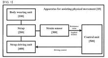
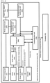
- FIG. 1 is a block diagram illustrating an apparatus for assisting physical movement, according to an embodiment of the inventive concept.
- an apparatus for assisting physical movement includes all or some of a body wearing unit 100, a strap 200, a strain sensor 300, a control unit 500, and a strap driving unit 400.
- the body wearing unit 100 is put on a specific body part of a user.
- the body wearing unit 100 is put on a body part to be assisted by the apparatus 10 for assisting physical movement and to be moved.
- the body wearing unit 100 may be a finger wearing unit.
- the body wearing unit 100 is put on a body part having a joint placed between the body part and a body part for placing the strap driving unit 400.
- the strap 200 is connected to one side of the body wearing unit 100. One end portion of the strap 200 is coupled to the body wearing unit 100, and an opposite end portion of the strap 200 is coupled to the strap driving unit 400 to be described later.
- the strap 200 includes a material elastically deformed in a length direction depending on bending (that is, the bending of a joint interposed between the body wearing unit 100 and the strap driving unit 400) of the body part having the body wearing unit 100.
- the strap 200 is designed to minimize resistance when a patient having a difficulty in applying force to the finger of the patient bends the finger,
- the strap 200 may have a band shape of a specific width such that the strain sensor 300 to be described later is disposed thereon.
- the strain sensor 300 is disposed on the strap 200 to measure the tension applied to the strap 200.
- the strain sensor 300 may be printed or attached onto one flat surface of the strap 200. In other words, the strain sensor 300 may be provided onto the one flat surface of the strap 200 to measure force applied to the strap 200 as the strap 200 is elastically deformed.
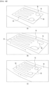
- the strain sensor 51 (or strain sensor 300) include a metal pattern 53 constituting a circuit, and a terminal 55 electrically connected with the metal pattern 53.
- the strain sensor 51 (or strain sensor 300) may be printed or attached onto one flat surface of the straps 200 and 41.
- the strain sensor 51 measures force applied to a strap 41 (or strap 200) by measuring resistance applied to the metal pattern 53 depending on the extent of the elastic deformation of the strain sensor 51 (or strain sensor 300), for example, the extent that the strap 41 (or strap 200) is stretched or shrunken in a lengthwise direction.
- the length of the metal pattern 53 of the strain sensor 51 (or strain sensor 300) increases, so the resistance value of the metal pattern 53 increases.
- the driving of the strap driving unit 400 is controlled based on the resistance value measured by the strain sensor 51 (or strain sensor 300).
- the strap driving unit 400 is linked to the strap 200. As the strap driving unit 400 rotates, the strap driving unit 400 winds or unwinds the strap 200. The strap driving unit 400 rotates in a stationary state such that a reference tension having a specific intensity is applied to the strain sensor 300. The strap driving unit 400 rotates in a specific direction as the tension applied to the strap 200 becomes higher or lower than the reference tension depending on the movement of a user.
- the strap driving unit 400 includes a strap winding roller 25, which is placed horizontally to a movement direction of the strap 200 to wind or unwind the strap 200 (or strap 41), and a strap driving motor 27 to reversibly rotate the strap winding roller 25. Accordingly, as the strap driving motor 27 reversibly rotates, the strap 200 (or strap 41) is wound around or unwound from the strap winding roller 25.
- the control unit 500 controls the strap driving unit 400 based on a measurement value (that is, resistance value) of the strain sensor 300.
- the control unit 500 controls the rotational direction of the strap driving unit 400 (for example, the rotation motor) by comparing the reference tension with the real-time applied tension as the control unit 500 sets the reference tension.
- the control unit 500 rotates the strap driving unit 400 in a direction of winding the strap 200, when the applied tension becomes less than the reference tension by a threshold value or more, and rotates the strap driving unit 400 in a direction unwinding the strap 200, when the applied tension becomes greater than the reference tension by a threshold value or more.
- the control unit 500 determines that the body part is in the stationary state without movement, so the control unit 500 does not drive the strap driving unit 400.
- the control unit 500 controls the strap driving unit 400 to apply the reference tension to the strap 200.
- the reference tension may be fixed to the minimum tension.
- the control unit 500 may repeatedly drive the strap driving unit 400 to apply the minimum tension to the strap when the user moves the body part.
- the reference tension may be set to a value equal to or greater than the minimum tension or periodically changed. For example, when the movement of the body part of the user is in the stationary state, the reference tension is set to the minimum tension. When the user body moves, the reference tension may be changed and set based on the applied tension.
- the control unit 500 may determine the movement direction of the user body without continuously driving the strap driving unit 400.
- the control unit 500 drives the strap driving unit 400 to reduce the applied tension of the strap and updates the reference tension such that the reference tension is matched to the applied tension.
- the control unit 500 determines the movement direction or the movement type (for example, bending or spreading) of the body part by comparing the reference tension with the applied tension. Accordingly, when the strap driving unit 400 stops after assisting the movement of the body part to be matched to the movement of the body part, the control unit 500 rotates and stops the strap driving unit 400 such that the resistance value corresponding to the reference tension is measured by the strain sensor 300. In other words, the control unit 500 controls the strap driving unit 400 to form a reference state in that the reference tension is applied to the strain sensor 300, such that the next movement direction of the body part is determined when the body part is stopped.
- the control unit 500 controls the strap driving unit 400 to form a reference state in that the reference tension is applied to the strain sensor 300, such that the next movement direction of the body part is determined when the body part is stopped.
- control unit 500 sets the maximum tension.
- the control unit 500 may stop the strap driving unit 400 or adjust the rotation speed of the strap driving unit 400, when the applied tension measured by the strain sensor 300 is within a specific range from the maximum tension.
- the body part of the patient is pulled with excessive tension, the body may be overwhelmed, so that the control unit 500 performs a control operation to prevent the maximum tension of from being applied in the exercise of the body part.
- the control unit 500 determines the bent joint as being spread due to the applied pressure equal to or lower than the reference tension and controls the strap driving unit 400 to rotate the strap 200 in a winding direction
- the moving speed of the body part becomes lower than the rotation speed of a motor, so the tension applied to the strap 200 may be increased to be almost the maximum tension.
- the control unit 500 may stop the motor rotation or reduce the rotation speed of the motor when the applied tension approaches the maximum tension.
- the bent posture may be a normal posture. Accordingly, the body part may be rapidly bent again as the patient loses the strength of the muscles of the body part after spreading the bent body part.
- the applied tension applied to the strap 200 may be gradually increased.
- the control unit 500 may increase the rotation speed of the strap driving unit 400 to rapidly unwind the strap 200, such that the applied tension is lowered.
- rehabilitation training suitable for the state of the patient may be provided.
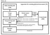
- an encoder 600 is further provided.
- the encoder 600 measures rotation data of the strap driving unit 400.
- the rotation data is a rotation speed or rotation angle.
- the rotation data may be used to calculate the extent to which the strap 200 is wound.
- the present length of the strap 200 between the body part and the strap driving unit 400 may be detected.
- the current length of the strap 200 between the body wearing unit 100 and the strap driving unit 400 may be used to calculate the present state of the body part.
- control unit 500 may store the maximum value and the minimum value of the encoder 600.
- control unit 500 sets the value of the encoder 600 to the minimum value when the body part is bent to the maximum extent, and sets the value of the encoder 600 to the maximum value when the body part is fully spread. Accordingly, the control unit 500 stops the rotation of the strap driving unit 400 when the measurement value of the encoder 600 reaches the maximum value or the minimum value, to prevent the strap driving unit 400 from assisting the body part beyond the movable rage of the body part.
- the control unit 500 may initially set the maximum value and minimum value of the measurement value of the encoder 600 by spreading and bending the body parts when the patient starts the rehabilitation training.
- the maximum value and the minimum value of the measurement value of the encoder 600 may be initially set by allowing the patient to exercise a joint from the maximum bending state to the maximum spread state in initial setting.
- a communication unit 700 may be further included.
- the communication unit 700 transmits rotation data, which is obtained from the encoder 600, to the terminal 20.
- the terminal 20 calculates the present length of the strap 200 between the body wearing unit 100 and the strap driving unit 400 by applying the rotation data to the entire length of the strap 200 and the circumferential length of the strap 200, and measures the arrangement state (for example, the bending angle of the body part) of the body part based on the present length of the strap 200 between the body wearing unit 100 and the strap driving unit 400. Thereafter, the terminal 20 generates and outputs a body image corresponding to the present arrangement state of the body part.
- the communication unit 700 transmits, to the terminal 20, the present arrangement state data of the body part calculated by the control unit 500 based on the rotation data obtained from the encoder 600.
- the encoder 600 transmits the rotation data to the control unit 500
- the control unit 500 calculates the present length of the strap 200 between the body wearing unit 100 and the strap driving unit 400 by applying the rotation data to the entire length of the strap 200 and the circumferential length of the strap 200, and measures the present arrangement state of the body part based on the present length of the strap 200 between the body wearing unit 100 and the strap driving unit 400.
- the control unit 500 transmits the arrangement state data to the communication unit 700
- the communication unit 700 transmits the arrangement state data to the terminal 20 through wired or wireless communication.
- the terminal 20 generates and output a body image corresponding to the present arrangement state of the body part.
- the body wearing unit 100 is a plurality of finger wearing units put on finger joints.
- the body wearing unit pulled by the strap driving unit 400 is a finger wearing unit will be described in detail with reference to FIGS. 4 to 8 .
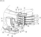
- the finger wearing unit 31 includes a silicon material, has the shape of a ring, and is coupled to each finger of the patient. Meanwhile, although the present embodiment has been described in that the finger wearing unit 31 is provided to correspond to, but is not limited thereto, each of an index finger, a middle finger, a ring finger, and a pinky finger.
- the apparatus 10 for assisting physical movement may further include a hand back wearing unit 21 having a strap driving unit 23.
- the hand back wearing unit 21 includes the strap driving unit 23 to wind or unwind a strap 41.
- the hand back wearing unit 21 includes a plurality of strap guide rollers 25 provided on the movement path of the strap 41 moving along a top surface of the hand back wearing unit 21, to guide the movement of the strap 41.
- the strap guide rollers 25 are provided corresponding to the number of straps 41, and spaced apart from each other by a specific distance.
- the strap 41 has the shape of a band having a specific width, and the hand back wearing unit 21 has a movement path including the strap 41.
- the hand back wearing unit 21 is provided on the back of the patient's hand, and the finger wearing unit 31 is coupled to each finger which is bent.
- the strap driving unit 23 is driven to wind or unwind the strap 41, the patient may perform the rehabilitation training by exercising the finger of the patient.
- a plurality of strap driving units wind or unwind straps linked to finger wearing units, respectively.
- the apparatus for assisting physical movement may further include a plurality of strap driving units to individually assist an exercise suitable for each finger connected with the strap.
- the control unit individually controls the strap driving unit connected with each strap, based on the applied tension measured by the strain sensor on each strap
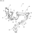
- a wrist support unit 61 and an upper limb support unit 101 are further provided.
- the wrist support unit 61 is provided on the wrist portion of the patient to support the wrist of the patient.
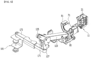
- the wrist support unit 61 includes a wrist rest 71 on which a wrist is rested, and a track 81 provided along the rotation trajectory of the wrist to guide the rotational movement of the wrist rest 71.
- the wrist rest 71 has a circular sectional shape, for example, a sectional shape of 'U' having an open upper portion to partially surround the wrist. Accordingly, the patient may stably rest the wrist to the wrist rest 71. In this case, a band is provided on the wrist rest 71 to fix the wrist such that the wrist is prevented from deviating from the wrist rest 71.
- a track 81 has a sectional shape of 'U' corresponding to the shape of the wrist rest 71.
- the track 81 is supported by a support 85.
- the support 85 includes a gap adjusting knob 87 to adjust a gap between the wrist rest 71 and an elbow rest 111 of the upper limb support unit 101 to be described later
- the track 81 includes a roller 91 corresponding to the rotational movement of the wrist rest 71 about the track 81.
- the roller 91 is provided to be movable while rolling the track 81, and linked to the wrist rest 71 by a roller support bracket 93.
- the wrist rest 71 moves along the track 81 by rotational force applied to the wrist of the patient.
- the wrist rest 71 moves along the track 81 such that the wrist smoothly rotates.
- the upper limb support unit 101 is disposed to be spaced apart from the wrist support unit, to support the upper limb of the patient.
- the upper limb support unit 101 includes an elbow rest 111 to rest an elbow of the patient and a lifting unit 121 to operate as the upper limb rested in the elbow rest 111 moves up and down.
- the elbow rest 111 has a sectional shape of 'U' having an open upper portion to partially surround the elbow. Accordingly, the patient may stably rest the elbow to the elbow rest 111. In this case, a band is provided on the elbow rest 111 to fix the elbow such that the elbow is prevented from deviating from the elbow rest 111.
- the elbow rest 111 is connected to a support 85 of the wrist support unit 61 by a connection bracket 115.
- the lifting unit 121 includes a pivot moving unit to pivot a pair of joint links 123 and 125 and a pivot joint 127 as a pair of joint links 123 and 125, a pivot joint 127, and the upper limb 7 rested on the elbow rest 111.
- the pivot moving unit includes a spring 133, a first wire pulley 141, a second wire pulley 143, a third wire pulley 145, a fourth wire pulley 147, and a wire 151.
- a pair of joint links include a first joint link 123 having one end portion coupled to the elbow rest 111 and a second joint link 125 coupled to an opposite end of the first joint link 123.
- the first joint link 123 has a hollowed bar shape. One end portion of the first joint link 123 is pivotally hinged to the elbow rest 111, and the opposite end portion of the first joint link 123 is pivotally hinged to one end portion of the second joint link 125 and the pivot joint 127.
- a spring 133 is received in the first joint link 123 to be compressed or extended.
- One end portion of the spring 133 is supported by the first joint link 123, and an opposite end portion of the spring 133 is linked to the wire 151.
- the first joint link 123 is not directly connected with the wire 151, and a connection block (not illustrated) is interposed between the first joint link 123 and the wire 151 such that the first joint link 123 is connected with the wire 151 through the connection block.
- One end portion of the second joint link 125 is hinged to tan opposite end portion of the first joint link 123 and the pivot joint 127.
- a plurality of wire pulleys are provided on the movement path of the wire 151.
- the plurality of wire pulleys include a first wire pulley 141 provided inside the first joint link 123 while being spaced apart a spring 133 by a specific distance, a second wire pulley 143 provided at a part where the first joint link 123 is hinged with one end portion of the second join link 125, a third wire pulley 145 provided at the pivot joint 127, and a fourth wire pulley 147 provided at an opposite end portion of the second joint link 125.
- the wire 151 has a specific length.
- the wire 151 is supported by the fourth wire pulley 147 through the first wire pulley 141, the second wire pulley 143, and the third wire pulley 145, while extending from an opposite end of the spring 133.
- the pivot joint 127 pivotally supports an opposite end portion of the first joint link 123 and one end portion of the second joint link 125.
- the third wire pulley 145 is provided at a lower portion of the pivot joint 127 to be exposed.
- the rehabilitation training for the upper limb 7 may be performed without force applied to the upper limb 7.
- the upper limb support unit 101 may further include a left-right operating unit 161 operating as the upper limb 7 moves left and right.
- the left-right operating unit 161 includes a pair of upper limbs 171 and 173 provided to be accessible each other and spaced apart from each other.
- Each end portion of the pair of arms 171 and 173, that is, each of end portions, which are opposite to each other, of the pair of arms 171 and 173 is pivotably hinged to the bracket 175 to correspond to the left and right movement of the upper limb 7.
- the opposite end portion of the arm 171, which is disposed adjacent to the pivot joint 127, of the pair of arms is hinged to the pivot joint 127, and the opposite end portion of the remaining arm 173 is hinged to a fixed member 181 to elastically support the robot 10 for upper limbs rehabilitation to a structure according to an embodiment of the inventive concept.
- the encoder 600 when the apparatus 10 for assisting physical movement includes a wrist support unit and an upper support unit, the encoder 600 further includes an arrangement state measuring unit 801 and a communication unit 700.
- the encoder 600 performs a role of measuring rotation data of the strap driving unit. Hereinafter, the details of the encoder 600 will be omitted.
- the arrangement state measuring unit 801 generates the arrangement state data by measuring the real-time arrangement state of the wrist support unit and the upper limb support unit.
- the real-time arrangement state may be measured through a sensor provided in the wrist support unit and the upper limb support unit.
- the arrangement state measuring unit 801 disposed on the wrist support unit may measure the rotation of the roller 91 on the U-shaped track 81 to measure the movement distance from one end portion of the track and to measure the present arrangement state.
- the arrangement state measuring unit 801 disposed at the upper limb support unit may calculate the present height of the upper limb unit based on the intensity of the tension applied to a spring 133.
- the manner that the arrangement state measuring unit 801 disposed on the wrist support unit and the upper limb support unit measures the real-time arrangement state is not limited thereto, but includes various manners.
- the communication unit 700 transmits, to the terminal 20, the rotation data or a finger arrangement state data obtained in the encoder 600, and the arrangement state data measured by the arrangement state measuring unit 801 disposed on the wrist support unit and the upper limb support unit.
- the terminal 20 generates and outputs a real-time body part image based on the received data. Accordingly, the user may perform the rehabilitation training while viewing an image representing the present operation of the patient, on a screen of the terminal 20.
- assist power appropriate to the exercise direction of a patient may be provided by detecting the physical movement of the patient through the comparison between the reference tension and the applied tension, thereby effectively providing the physical rehabilitation training.
Landscapes
- Health & Medical Sciences (AREA)
- Epidemiology (AREA)
- Pain & Pain Management (AREA)
- Physical Education & Sports Medicine (AREA)
- Rehabilitation Therapy (AREA)
- Life Sciences & Earth Sciences (AREA)
- Animal Behavior & Ethology (AREA)
- General Health & Medical Sciences (AREA)
- Public Health (AREA)
- Veterinary Medicine (AREA)
- Rehabilitation Tools (AREA)
Claims (9)
- Vorrichtung zum Unterstützen einer physischen Bewegung, wobei die Vorrichtung umfasst:eine Körpertrageeinheit (100), um, in Verwendung, an einem spezifischen Körper eines Benutzers angelegt zu sein;einen Gurt (200, 41), der mit einer Seite der Körpertrageeinheit (100) verbunden ist;einen Dehnungssensor (300, 51), der an dem Gurt (200, 41) vorgesehen ist, um einen Zug zu messen, der auf den Gurt (200, 41) aufgebracht wird;eine Gurtantriebseinheit (400, 23), die mit dem Gurt (200, 41) verbunden ist, um den Gurt abhängig von einer Drehung auf- oder abzuwickeln;eine Steuereinheit (500), die dazu konfiguriert ist, die Gurtantriebseinheit (400, 23) basierend auf einem Messwert des Dehnungssensors (300, 51) zu steuern; undeinen Encoder (600), um Drehdaten der Gurtantriebseinheit (400, 23) zu messen, undwobei die Gurtantriebseinheit (400, 23) dazu konfiguriert ist, sich in einem stationären Zustand derart zu drehen, dass ein Referenzzug, der eine spezifische Intensität aufweist, auf den Dehnungssensor (300, 51) aufgebracht wird; und sich in einer spezifischen Richtung zu drehen, wenn der auf den Gurt (200, 41) aufgebrachte Zug abhängig von einer Bewegung eines Benutzers höher oder niedriger als der Referenzzug wird, undwobei die Steuereinheit (500) dazu konfiguriert ist, den Referenzzug und einen maximalen Zug einzustellen, unddie Steuereinheit (500) dazu konfiguriert ist, die Gurtantriebseinheit (400, 23) in einer Richtung eines Aufwickelns des Gurts (200, 41) zu drehen, wenn der aufgebrachte Zug um einen Schwellenwert oder mehr niedriger als der Referenzzug wird; und die Gurtantriebseinheit (400, 23) in einer Richtung eines Abwickelns des Gurts (200, 41) zu drehen, wenn der aufgebrachte Zug um einen Schwellenwert oder mehr größer als der Referenzzug wird, unddadurch gekennzeichnet, dassdie Vorrichtung zum Unterstützen einer physischen Bewegung ferner umfasst:
eine Kommunikationseinheit (700), um die Drehdaten zu einem Terminal zu übertragen, undwobei das Terminal ein den Drehdaten entsprechendes Körperbild erzeugt und ausgibt. - Vorrichtung nach Anspruch 1, wobei, wenn der Referenzzug sich an den maximalen Zug annähert, die Steuereinheit (500) die Gurtantriebseinheit (400, 23) antreibt, um den aufgebrachten Zug des Gurts (200, 41) zu reduzieren, und den Referenzzug derart aktualisiert, dass der Referenzzug mit dem aufgebrachten Zug in Übereinstimmung gebracht wird.
- Vorrichtung nach Anspruch 1, wobei die Körpertrageeinheit (100) umfasst:
eine Vielzahl von Fingertrageeinheiten (31), die an Fingergelenken angelegt sind. - Vorrichtung nach Anspruch 3, ferner umfassend:
eine Vielzahl von Gurtantriebseinheiten (400, 23), die einen Gurt (200, 41) auf- oder abwickeln, der jeweils mit der Fingertrageeinheit (31) verbunden ist. - Vorrichtung nach Anspruch 1, wobei die Drehdaten eine Umdrehung pro Minute (RPM) oder ein Drehwinkel sind.
- Vorrichtung nach Anspruch 1, ferner umfassend:eine Handgelenkstützeinheit (61), die an einem Handgelenksabschnitt eines Patienten vorgesehen ist, um ein Handgelenk des Patienten zu stützen (85); undeine Oberarmstützeinheit (101), die von der Handgelenkstützeinheit (61) beabstandet ist, um einen Oberarm (7) des Patienten zu stützen,wenn die Körpertrageeinheit (100) eine Fingertrageeinheit (31) ist, die an einem Handrücken eines Patienten vorgesehen ist, um ein Rehabilitationstraining für einen Finger des Patienten durchzuführen.
- Vorrichtung nach Anspruch 6, wobei die Oberarmstützeinheit (101) umfasst:eine Ellenbogenstütze (111, 11), um einen Ellenbogen des Patienten abzustützen; undeine Anhebeeinheit (121), um zu arbeiten, wenn sich der Oberarm (7), der in der Ellenbogenstütze (111, 11) abgestützt ist, auf- und abbewegt.
- Vorrichtung nach Anspruch 7, wobei die Anhebeeinheit (121) umfasst:eine erste Gelenkverbindung (123), die an der Ellenbogenstütze (111, 11) schwenkbar angelenkt ist;eine zweite Gelenkverbindung (125), die an der ersten Gelenkverbindung (123) schwenkbar angelenkt ist;ein Drehgelenk (127), das an der ersten Gelenkverbindung (123) und der zweiten Gelenkverbindung (125) schwenkbar angelenkt ist; undeine Drehbewegungseinheit, um die erste Gelenkverbindung (123), die zweite Gelenkverbindung (125) und das Drehgelenk (127) schwenkbar zu bewegen, wenn sich der Oberarm (7), der in der Ellenbogenstütze (111, 11) abgestützt ist, auf- und abbewegt.
- Vorrichtung nach Anspruch 6, ferner umfassend:den Encoder (600), um Drehdaten der Gurtantriebseinheit (400, 23) zu messen;eine Anordnungszustandsmesseinheit (801), um durch Messen eines Echtzeitanordnungszustands der Handgelenkstützeinheit (61) und der Extremitätenstütz (85)-Einheit Anordnungszustandsdaten zu erzeugen; unddie Kommunikationseinheit (700), um die Drehdaten und die Anordnungszustandsdaten zu übertragen,wobei das Terminal ein Echtzeitkörperbild basierend auf den Drehdaten und den Anordnungszustandsdaten erzeugt und ausgibt.
Applications Claiming Priority (3)
| Application Number | Priority Date | Filing Date | Title |
|---|---|---|---|
| KR20170082706 | 2017-06-29 | ||
| KR1020170111093A KR102021744B1 (ko) | 2017-06-29 | 2017-08-31 | 신체움직임보조장치 |
| PCT/KR2018/007174 WO2019004676A1 (ko) | 2017-06-29 | 2018-06-25 | 신체움직임보조장치 |
Publications (3)
| Publication Number | Publication Date |
|---|---|
| EP3646843A1 EP3646843A1 (de) | 2020-05-06 |
| EP3646843A4 EP3646843A4 (de) | 2020-06-24 |
| EP3646843B1 true EP3646843B1 (de) | 2022-01-19 |
Family
ID=64742398
Family Applications (1)
| Application Number | Title | Priority Date | Filing Date |
|---|---|---|---|
| EP18823136.9A Active EP3646843B1 (de) | 2017-06-29 | 2018-06-25 | Vorrichtung zur unterstützung der körperbewegung |
Country Status (2)
| Country | Link |
|---|---|
| EP (1) | EP3646843B1 (de) |
| WO (1) | WO2019004676A1 (de) |
Families Citing this family (3)
| Publication number | Priority date | Publication date | Assignee | Title |
|---|---|---|---|---|
| FR3105056B1 (fr) * | 2019-12-20 | 2023-09-08 | Commissariat Energie Atomique | Equilibreur de charge passif |
| ES2974081T3 (es) | 2021-10-26 | 2024-06-25 | Gesnaer Consulting Slne | Sistema de exoesqueleto equipado con sensores |
| CN115227544B (zh) * | 2022-07-11 | 2025-01-03 | 复旦大学 | 一种上肢单臂康复训练机器人及其操作方法 |
Family Cites Families (9)
| Publication number | Priority date | Publication date | Assignee | Title |
|---|---|---|---|---|
| US8905950B2 (en) * | 2008-03-04 | 2014-12-09 | Bonutti Research, Inc. | Shoulder ROM orthosis |
| KR101163903B1 (ko) | 2010-08-13 | 2012-07-09 | 한국과학기술원 | 뇌졸중 환자의 상지 재활을 위한 외골격 로봇 |
| KR101290172B1 (ko) * | 2011-10-26 | 2013-07-30 | 한양대학교 에리카산학협력단 | 근육 활성화도 측정 장치 |
| US9120220B2 (en) * | 2012-02-29 | 2015-09-01 | GM Global Technology Operations LLC | Control of a glove-based grasp assist device |
| KR101511427B1 (ko) * | 2012-08-30 | 2015-04-10 | 서울대학교산학협력단 | 편마비 치료 장치 |
| KR102122856B1 (ko) * | 2013-12-17 | 2020-06-15 | 삼성전자주식회사 | 보행 보조 장치 및 그 제어 방법 |
| KR101578609B1 (ko) * | 2014-05-28 | 2015-12-17 | 경북대학교 산학협력단 | 하지 근력 측정 시스템 |
| KR101603162B1 (ko) * | 2014-11-24 | 2016-03-17 | 대한민국 | 모터에 의하여 하중을 보상하는 상지 보조 장치 |
| JP6489422B2 (ja) * | 2015-01-28 | 2019-03-27 | パナソニックIpマネジメント株式会社 | アシストウェア、アシストウェアの作動方法、及び、制御プログラム |
-
2018
- 2018-06-25 EP EP18823136.9A patent/EP3646843B1/de active Active
- 2018-06-25 WO PCT/KR2018/007174 patent/WO2019004676A1/ko not_active Ceased
Also Published As
| Publication number | Publication date |
|---|---|
| EP3646843A1 (de) | 2020-05-06 |
| EP3646843A4 (de) | 2020-06-24 |
| WO2019004676A1 (ko) | 2019-01-03 |
Similar Documents
| Publication | Publication Date | Title |
|---|---|---|
| US20200129360A1 (en) | Apparatus for assisting physical movement | |
| KR102284895B1 (ko) | 상지 재활 로봇 | |
| EP2723458B1 (de) | Vorrichtung und verfahren zur rehabilitation verletzter gliedmassen | |
| KR101099078B1 (ko) | 전동 팔꿈치 재활보조기구 | |
| KR101667179B1 (ko) | 사용자-연계 휴먼-머신 인터페이스 시스템 및 그의 외골격 제어 방법 | |
| EP2138146B1 (de) | Rehabilitationsunterstützungsvorrichtung | |
| US8968220B2 (en) | Wearable robotic system for rehabilitation training of the upper limbs | |
| EP3522838B1 (de) | Armhebeunterstützungsvorrichtung | |
| EP3646843B1 (de) | Vorrichtung zur unterstützung der körperbewegung | |
| EP2931203B1 (de) | Rehabilitationsvorrichtung mit schattenbein | |
| KR102207991B1 (ko) | 시트형 근력 보조 슈트 | |
| WO2008047355A2 (en) | Methods and gyroscopic apparatus for rehabilitation training | |
| RU2720323C1 (ru) | Тренажер с биологической обратной связью для реабилитации суставов кистей и пальцев рук и способ его работы | |
| JP2003190234A (ja) | 多自由度下肢リハビリ支援装置 | |
| CN110974600A (zh) | 一种基于柔性触觉的可穿戴式脑卒中康复装置 | |
| US11730658B2 (en) | Device for assisting body movement | |
| WO2018146378A1 (en) | Device for measuring and teaching human position and/or movement | |
| KR101500946B1 (ko) | 허리작업 부하경감을 위한 파워스틱 및 그 제어방법 | |
| Yu et al. | Development of an active arm weight-bearing unit and its application in hemiplegic arm rehabilitation | |
| CN118204953A (zh) | 柔性外骨骼穿戴设备 |
Legal Events
| Date | Code | Title | Description |
|---|---|---|---|
| STAA | Information on the status of an ep patent application or granted ep patent |
Free format text: STATUS: THE INTERNATIONAL PUBLICATION HAS BEEN MADE |
|
| PUAI | Public reference made under article 153(3) epc to a published international application that has entered the european phase |
Free format text: ORIGINAL CODE: 0009012 |
|
| STAA | Information on the status of an ep patent application or granted ep patent |
Free format text: STATUS: REQUEST FOR EXAMINATION WAS MADE |
|
| 17P | Request for examination filed |
Effective date: 20200120 |
|
| AK | Designated contracting states |
Kind code of ref document: A1 Designated state(s): AL AT BE BG CH CY CZ DE DK EE ES FI FR GB GR HR HU IE IS IT LI LT LU LV MC MK MT NL NO PL PT RO RS SE SI SK SM TR |
|
| AX | Request for extension of the european patent |
Extension state: BA ME |
|
| A4 | Supplementary search report drawn up and despatched |
Effective date: 20200527 |
|
| RIC1 | Information provided on ipc code assigned before grant |
Ipc: A61H 1/02 20060101AFI20200519BHEP Ipc: A61H 3/00 20060101ALI20200519BHEP |
|
| DAV | Request for validation of the european patent (deleted) | ||
| DAX | Request for extension of the european patent (deleted) | ||
| STAA | Information on the status of an ep patent application or granted ep patent |
Free format text: STATUS: EXAMINATION IS IN PROGRESS |
|
| 17Q | First examination report despatched |
Effective date: 20210125 |
|
| GRAP | Despatch of communication of intention to grant a patent |
Free format text: ORIGINAL CODE: EPIDOSNIGR1 |
|
| STAA | Information on the status of an ep patent application or granted ep patent |
Free format text: STATUS: GRANT OF PATENT IS INTENDED |
|
| INTG | Intention to grant announced |
Effective date: 20210907 |
|
| GRAS | Grant fee paid |
Free format text: ORIGINAL CODE: EPIDOSNIGR3 |
|
| GRAA | (expected) grant |
Free format text: ORIGINAL CODE: 0009210 |
|
| STAA | Information on the status of an ep patent application or granted ep patent |
Free format text: STATUS: THE PATENT HAS BEEN GRANTED |
|
| AK | Designated contracting states |
Kind code of ref document: B1 Designated state(s): AL AT BE BG CH CY CZ DE DK EE ES FI FR GB GR HR HU IE IS IT LI LT LU LV MC MK MT NL NO PL PT RO RS SE SI SK SM TR |
|
| REG | Reference to a national code |
Ref country code: GB Ref legal event code: FG4D |
|
| REG | Reference to a national code |
Ref country code: CH Ref legal event code: EP |
|
| REG | Reference to a national code |
Ref country code: DE Ref legal event code: R096 Ref document number: 602018029865 Country of ref document: DE |
|
| REG | Reference to a national code |
Ref country code: AT Ref legal event code: REF Ref document number: 1463370 Country of ref document: AT Kind code of ref document: T Effective date: 20220215 |
|
| REG | Reference to a national code |
Ref country code: IE Ref legal event code: FG4D |
|
| REG | Reference to a national code |
Ref country code: LT Ref legal event code: MG9D |
|
| REG | Reference to a national code |
Ref country code: NL Ref legal event code: MP Effective date: 20220119 |
|
| REG | Reference to a national code |
Ref country code: AT Ref legal event code: MK05 Ref document number: 1463370 Country of ref document: AT Kind code of ref document: T Effective date: 20220119 |
|
| PG25 | Lapsed in a contracting state [announced via postgrant information from national office to epo] |
Ref country code: NL Free format text: LAPSE BECAUSE OF FAILURE TO SUBMIT A TRANSLATION OF THE DESCRIPTION OR TO PAY THE FEE WITHIN THE PRESCRIBED TIME-LIMIT Effective date: 20220119 |
|
| PG25 | Lapsed in a contracting state [announced via postgrant information from national office to epo] |
Ref country code: SE Free format text: LAPSE BECAUSE OF FAILURE TO SUBMIT A TRANSLATION OF THE DESCRIPTION OR TO PAY THE FEE WITHIN THE PRESCRIBED TIME-LIMIT Effective date: 20220119 Ref country code: RS Free format text: LAPSE BECAUSE OF FAILURE TO SUBMIT A TRANSLATION OF THE DESCRIPTION OR TO PAY THE FEE WITHIN THE PRESCRIBED TIME-LIMIT Effective date: 20220119 Ref country code: PT Free format text: LAPSE BECAUSE OF FAILURE TO SUBMIT A TRANSLATION OF THE DESCRIPTION OR TO PAY THE FEE WITHIN THE PRESCRIBED TIME-LIMIT Effective date: 20220519 Ref country code: NO Free format text: LAPSE BECAUSE OF FAILURE TO SUBMIT A TRANSLATION OF THE DESCRIPTION OR TO PAY THE FEE WITHIN THE PRESCRIBED TIME-LIMIT Effective date: 20220419 Ref country code: LT Free format text: LAPSE BECAUSE OF FAILURE TO SUBMIT A TRANSLATION OF THE DESCRIPTION OR TO PAY THE FEE WITHIN THE PRESCRIBED TIME-LIMIT Effective date: 20220119 Ref country code: HR Free format text: LAPSE BECAUSE OF FAILURE TO SUBMIT A TRANSLATION OF THE DESCRIPTION OR TO PAY THE FEE WITHIN THE PRESCRIBED TIME-LIMIT Effective date: 20220119 Ref country code: ES Free format text: LAPSE BECAUSE OF FAILURE TO SUBMIT A TRANSLATION OF THE DESCRIPTION OR TO PAY THE FEE WITHIN THE PRESCRIBED TIME-LIMIT Effective date: 20220119 Ref country code: BG Free format text: LAPSE BECAUSE OF FAILURE TO SUBMIT A TRANSLATION OF THE DESCRIPTION OR TO PAY THE FEE WITHIN THE PRESCRIBED TIME-LIMIT Effective date: 20220419 |
|
| PG25 | Lapsed in a contracting state [announced via postgrant information from national office to epo] |
Ref country code: PL Free format text: LAPSE BECAUSE OF FAILURE TO SUBMIT A TRANSLATION OF THE DESCRIPTION OR TO PAY THE FEE WITHIN THE PRESCRIBED TIME-LIMIT Effective date: 20220119 Ref country code: LV Free format text: LAPSE BECAUSE OF FAILURE TO SUBMIT A TRANSLATION OF THE DESCRIPTION OR TO PAY THE FEE WITHIN THE PRESCRIBED TIME-LIMIT Effective date: 20220119 Ref country code: GR Free format text: LAPSE BECAUSE OF FAILURE TO SUBMIT A TRANSLATION OF THE DESCRIPTION OR TO PAY THE FEE WITHIN THE PRESCRIBED TIME-LIMIT Effective date: 20220420 Ref country code: FI Free format text: LAPSE BECAUSE OF FAILURE TO SUBMIT A TRANSLATION OF THE DESCRIPTION OR TO PAY THE FEE WITHIN THE PRESCRIBED TIME-LIMIT Effective date: 20220119 Ref country code: AT Free format text: LAPSE BECAUSE OF FAILURE TO SUBMIT A TRANSLATION OF THE DESCRIPTION OR TO PAY THE FEE WITHIN THE PRESCRIBED TIME-LIMIT Effective date: 20220119 |
|
| PG25 | Lapsed in a contracting state [announced via postgrant information from national office to epo] |
Ref country code: IS Free format text: LAPSE BECAUSE OF FAILURE TO SUBMIT A TRANSLATION OF THE DESCRIPTION OR TO PAY THE FEE WITHIN THE PRESCRIBED TIME-LIMIT Effective date: 20220519 |
|
| REG | Reference to a national code |
Ref country code: DE Ref legal event code: R097 Ref document number: 602018029865 Country of ref document: DE |
|
| PG25 | Lapsed in a contracting state [announced via postgrant information from national office to epo] |
Ref country code: SM Free format text: LAPSE BECAUSE OF FAILURE TO SUBMIT A TRANSLATION OF THE DESCRIPTION OR TO PAY THE FEE WITHIN THE PRESCRIBED TIME-LIMIT Effective date: 20220119 Ref country code: SK Free format text: LAPSE BECAUSE OF FAILURE TO SUBMIT A TRANSLATION OF THE DESCRIPTION OR TO PAY THE FEE WITHIN THE PRESCRIBED TIME-LIMIT Effective date: 20220119 Ref country code: RO Free format text: LAPSE BECAUSE OF FAILURE TO SUBMIT A TRANSLATION OF THE DESCRIPTION OR TO PAY THE FEE WITHIN THE PRESCRIBED TIME-LIMIT Effective date: 20220119 Ref country code: EE Free format text: LAPSE BECAUSE OF FAILURE TO SUBMIT A TRANSLATION OF THE DESCRIPTION OR TO PAY THE FEE WITHIN THE PRESCRIBED TIME-LIMIT Effective date: 20220119 Ref country code: DK Free format text: LAPSE BECAUSE OF FAILURE TO SUBMIT A TRANSLATION OF THE DESCRIPTION OR TO PAY THE FEE WITHIN THE PRESCRIBED TIME-LIMIT Effective date: 20220119 Ref country code: CZ Free format text: LAPSE BECAUSE OF FAILURE TO SUBMIT A TRANSLATION OF THE DESCRIPTION OR TO PAY THE FEE WITHIN THE PRESCRIBED TIME-LIMIT Effective date: 20220119 |
|
| PLBE | No opposition filed within time limit |
Free format text: ORIGINAL CODE: 0009261 |
|
| STAA | Information on the status of an ep patent application or granted ep patent |
Free format text: STATUS: NO OPPOSITION FILED WITHIN TIME LIMIT |
|
| PG25 | Lapsed in a contracting state [announced via postgrant information from national office to epo] |
Ref country code: AL Free format text: LAPSE BECAUSE OF FAILURE TO SUBMIT A TRANSLATION OF THE DESCRIPTION OR TO PAY THE FEE WITHIN THE PRESCRIBED TIME-LIMIT Effective date: 20220119 |
|
| 26N | No opposition filed |
Effective date: 20221020 |
|
| PG25 | Lapsed in a contracting state [announced via postgrant information from national office to epo] |
Ref country code: MC Free format text: LAPSE BECAUSE OF FAILURE TO SUBMIT A TRANSLATION OF THE DESCRIPTION OR TO PAY THE FEE WITHIN THE PRESCRIBED TIME-LIMIT Effective date: 20220119 |
|
| REG | Reference to a national code |
Ref country code: CH Ref legal event code: PL |
|
| REG | Reference to a national code |
Ref country code: BE Ref legal event code: MM Effective date: 20220630 |
|
| PG25 | Lapsed in a contracting state [announced via postgrant information from national office to epo] |
Ref country code: SI Free format text: LAPSE BECAUSE OF FAILURE TO SUBMIT A TRANSLATION OF THE DESCRIPTION OR TO PAY THE FEE WITHIN THE PRESCRIBED TIME-LIMIT Effective date: 20220119 |
|
| PG25 | Lapsed in a contracting state [announced via postgrant information from national office to epo] |
Ref country code: LU Free format text: LAPSE BECAUSE OF NON-PAYMENT OF DUE FEES Effective date: 20220625 Ref country code: LI Free format text: LAPSE BECAUSE OF NON-PAYMENT OF DUE FEES Effective date: 20220630 Ref country code: IE Free format text: LAPSE BECAUSE OF NON-PAYMENT OF DUE FEES Effective date: 20220625 Ref country code: CH Free format text: LAPSE BECAUSE OF NON-PAYMENT OF DUE FEES Effective date: 20220630 |
|
| PG25 | Lapsed in a contracting state [announced via postgrant information from national office to epo] |
Ref country code: BE Free format text: LAPSE BECAUSE OF NON-PAYMENT OF DUE FEES Effective date: 20220630 |
|
| PG25 | Lapsed in a contracting state [announced via postgrant information from national office to epo] |
Ref country code: IT Free format text: LAPSE BECAUSE OF FAILURE TO SUBMIT A TRANSLATION OF THE DESCRIPTION OR TO PAY THE FEE WITHIN THE PRESCRIBED TIME-LIMIT Effective date: 20220119 |
|
| PG25 | Lapsed in a contracting state [announced via postgrant information from national office to epo] |
Ref country code: MK Free format text: LAPSE BECAUSE OF FAILURE TO SUBMIT A TRANSLATION OF THE DESCRIPTION OR TO PAY THE FEE WITHIN THE PRESCRIBED TIME-LIMIT Effective date: 20220119 Ref country code: CY Free format text: LAPSE BECAUSE OF FAILURE TO SUBMIT A TRANSLATION OF THE DESCRIPTION OR TO PAY THE FEE WITHIN THE PRESCRIBED TIME-LIMIT Effective date: 20220119 |
|
| PG25 | Lapsed in a contracting state [announced via postgrant information from national office to epo] |
Ref country code: HU Free format text: LAPSE BECAUSE OF FAILURE TO SUBMIT A TRANSLATION OF THE DESCRIPTION OR TO PAY THE FEE WITHIN THE PRESCRIBED TIME-LIMIT; INVALID AB INITIO Effective date: 20180625 |
|
| PG25 | Lapsed in a contracting state [announced via postgrant information from national office to epo] |
Ref country code: MT Free format text: LAPSE BECAUSE OF FAILURE TO SUBMIT A TRANSLATION OF THE DESCRIPTION OR TO PAY THE FEE WITHIN THE PRESCRIBED TIME-LIMIT Effective date: 20220119 |
|
| PGFP | Annual fee paid to national office [announced via postgrant information from national office to epo] |
Ref country code: DE Payment date: 20250617 Year of fee payment: 8 |
|
| PGFP | Annual fee paid to national office [announced via postgrant information from national office to epo] |
Ref country code: GB Payment date: 20250620 Year of fee payment: 8 |
|
| PGFP | Annual fee paid to national office [announced via postgrant information from national office to epo] |
Ref country code: FR Payment date: 20250618 Year of fee payment: 8 |
|
| PG25 | Lapsed in a contracting state [announced via postgrant information from national office to epo] |
Ref country code: TR Free format text: LAPSE BECAUSE OF FAILURE TO SUBMIT A TRANSLATION OF THE DESCRIPTION OR TO PAY THE FEE WITHIN THE PRESCRIBED TIME-LIMIT Effective date: 20220119 |