EP3647004A1 - Maschine zum aufteilen von platten aus holz oder dergleichen - Google Patents
Maschine zum aufteilen von platten aus holz oder dergleichen Download PDFInfo
- Publication number
- EP3647004A1 EP3647004A1 EP19207201.5A EP19207201A EP3647004A1 EP 3647004 A1 EP3647004 A1 EP 3647004A1 EP 19207201 A EP19207201 A EP 19207201A EP 3647004 A1 EP3647004 A1 EP 3647004A1
- Authority
- EP
- European Patent Office
- Prior art keywords
- panels
- cutting machine
- support
- cutting
- panel
- Prior art date
- Legal status (The legal status is an assumption and is not a legal conclusion. Google has not performed a legal analysis and makes no representation as to the accuracy of the status listed.)
- Granted
Links
Images


Classifications
-
- B—PERFORMING OPERATIONS; TRANSPORTING
- B27—WORKING OR PRESERVING WOOD OR SIMILAR MATERIAL; NAILING OR STAPLING MACHINES IN GENERAL
- B27B—SAWS FOR WOOD OR SIMILAR MATERIAL; COMPONENTS OR ACCESSORIES THEREFOR
- B27B5/00—Sawing machines working with circular or cylindrical saw blades; Components or equipment therefor
- B27B5/02—Sawing machines working with circular or cylindrical saw blades; Components or equipment therefor characterised by a special purpose only
- B27B5/06—Sawing machines working with circular or cylindrical saw blades; Components or equipment therefor characterised by a special purpose only for dividing plates in parts of determined size, e.g. panels
- B27B5/065—Sawing machines working with circular or cylindrical saw blades; Components or equipment therefor characterised by a special purpose only for dividing plates in parts of determined size, e.g. panels with feedable saw blades, e.g. arranged on a carriage
-
- B—PERFORMING OPERATIONS; TRANSPORTING
- B25—HAND TOOLS; PORTABLE POWER-DRIVEN TOOLS; MANIPULATORS
- B25J—MANIPULATORS; CHAMBERS PROVIDED WITH MANIPULATION DEVICES
- B25J11/00—Manipulators not otherwise provided for
-
- B—PERFORMING OPERATIONS; TRANSPORTING
- B25—HAND TOOLS; PORTABLE POWER-DRIVEN TOOLS; MANIPULATORS
- B25J—MANIPULATORS; CHAMBERS PROVIDED WITH MANIPULATION DEVICES
- B25J15/00—Gripping heads and other end effectors
- B25J15/0052—Gripping heads and other end effectors multiple gripper units or multiple end effectors
- B25J15/0061—Gripping heads and other end effectors multiple gripper units or multiple end effectors mounted on a modular gripping structure
-
- B—PERFORMING OPERATIONS; TRANSPORTING
- B25—HAND TOOLS; PORTABLE POWER-DRIVEN TOOLS; MANIPULATORS
- B25J—MANIPULATORS; CHAMBERS PROVIDED WITH MANIPULATION DEVICES
- B25J15/00—Gripping heads and other end effectors
- B25J15/02—Gripping heads and other end effectors servo-actuated
- B25J15/0253—Gripping heads and other end effectors servo-actuated comprising parallel grippers
-
- B—PERFORMING OPERATIONS; TRANSPORTING
- B25—HAND TOOLS; PORTABLE POWER-DRIVEN TOOLS; MANIPULATORS
- B25J—MANIPULATORS; CHAMBERS PROVIDED WITH MANIPULATION DEVICES
- B25J15/00—Gripping heads and other end effectors
- B25J15/06—Gripping heads and other end effectors with vacuum or magnetic holding means
- B25J15/0616—Gripping heads and other end effectors with vacuum or magnetic holding means with vacuum
-
- B—PERFORMING OPERATIONS; TRANSPORTING
- B27—WORKING OR PRESERVING WOOD OR SIMILAR MATERIAL; NAILING OR STAPLING MACHINES IN GENERAL
- B27B—SAWS FOR WOOD OR SIMILAR MATERIAL; COMPONENTS OR ACCESSORIES THEREFOR
- B27B31/00—Arrangements for conveying, loading, turning, adjusting, or discharging the log or timber, specially designed for saw mills or sawing machines
Definitions
- the present invention relates to a cutting machine to cut panels made of wood or the like.
- a cutting machine comprising a support frame defining a substantially horizontal support surface for at least one panel made of wood or the like; a cutting station; a main pusher to move at least one first panel in a first direction through the cutting station; a secondary pusher to move at least one second panel in the first direction through the cutting station; and a cutting device mounted in the cutting station to move in a second direction and along a cutting surface, which are perpendicular to the first direction so as to cut the panels.
- the support surface is defined by a roller device mounted upstream of the cutting station, an output table mounted downstream of the cutting station, and a discharge trapdoor mounted between the roller device and the output table, downstream of the cutting surface, to discharge the swarf generated by the cutting device beneath the support surface.
- the cutting machine also comprises an end-of-travel device, which is mounted in the area of the output table parallel to the first direction and has at least one end-of-travel member movable between a raised operating position, in which the end-of-travel member protrudes above the support surface, and a lowered rest position, in which the end-of-travel member extends below the support surface.
- the cutting machine is further equipped with a robotic manipulator mounted downstream of the output table to collect the components separated from the panels by the cutting device and unload them from the cutting machine or feed them again to the main pusher and/or to the secondary pusher to perform further cuts.
- the robotic manipulator comprises a base, a system of articulated arms that are connected to each other and to the base, and a gripping unit attached to the articulated arms.
- the gripping unit comprises an elongated cross member, which is rotatably coupled to the telescopic arms and supports a pair of parallel gripping arms.
- the gripping arms extend transversely to the cross member, are movable relative to one another along the cross member, and are provided with respective suction cups that can be connected to a pneumatic suction device.
- Each gripping arm is also provided with a pushing device, which is movable along the gripping arm and comprises a pushing pin movable between an extracted operating position and a retracted rest position.
- the known cutting machines of the type described above have some drawbacks mainly due to the fact that the robotic manipulator has a relatively low flexibility, since the two pushing devices are unable to correctly position the components against the end-of-travel device and move stacks of overlapping components on the support surface.
- the object of the present invention is to provide a cutting machine to cut panels made of wood or the like, which is free from the drawbacks described above and simple and inexpensive to implement.
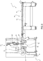
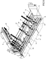
- number 1 indicates, as a whole, a cutting machine for cutting flat panels 2 made of wood or the like, substantially rectangular in shape.
- the machine 1 comprises a portal frame 3, which substantially has the shape of a parallelepiped with a rectangular base, extends in a horizontal direction 4, and is provided with four vertical edges, each defined by a respective upright 5 parallel to a vertical direction 6 transverse to direction 4.
- Each upright 5 is aligned with a corresponding upright 5 in direction 4 and with a corresponding upright 5 in a horizontal direction 7 orthogonal to directions 4 and 6.
- the frame 3 also comprises two longitudinal guide members 8 parallel to each other, each of which extends in direction 4 and connects two corresponding uprights 5 to each other; a cross member 9, which extends in direction 7, is delimited by a flat upper face 10 perpendicular to direction 6, and connects two of the four uprights 5 to each other; and two support devices 11, which are arranged on opposite sides of the cross member 9 in direction 4, and define, together with the face 10, a substantially horizontal support surface P for the panels 2.
- the device 11 upstream of the cross member 9 comprises a plurality of roller bars 12 parallel to each other and to direction 4, and the device 11 downstream of the cross member 9 comprises an output table 13.
- the frame 3 is further provided with a discharge trapdoor 14 mounted between the cross member 9 and the table 13 to discharge the swarf generated by the cutting of the panels 2 beneath the surface P.
- the trapdoor 14 comprises two support plates 15, 16, which are aligned with each other in direction 7, and are movable independently of one another, under the thrust of respective actuating devices (not shown), between respective raised closing positions, in which the plates 15, 16 are coplanar with the surface P, and respective lowered opening positions, in which the plates 15, 16 allow the swarf to fall below the surface P.
- the plate 15 has a length, as measured parallel to direction 7, less than the length of the plate 16, also as measured parallel to direction 7.
- the machine 1 also comprises a cutting station 17, which is formed next to the cross member 9 and the respective uprights 5, and is provided with a cutting assembly 18 of a known type coupled in a known manner to the cross member 9 so as to move rectilinearly in direction 7 relative to the frame 3 and under the thrust of a known, not shown actuating device.
- the cutting assembly 18 has a blade 19 and an engraver (not shown) mounted so as to rotate about respective axes of rotation, which are parallel to each other and to direction 4, and to move rectilinearly in direction 6 between respective lowered rest positions, in which the blade 19 and the engraver (not shown) are arranged below the surface P to allow the panels 2 to be fed along the surface P, and respective raised operating positions, in which the blade 19 and the engraver (not shown) protrude through the cross member 9 above the surface P in order to cut the panels 2.
- the blade 19 and the engraver (not shown) are also moved by the assembly 18 along a cutting surface T formed through the cross member 9 perpendicularly to direction 4 with alternating rectilinear motion comprising a forward stroke, in which the engraver (not shown), arranged in front of the blade 19 in the direction 7 of feeding of the assembly 18, engraves the panel 2 arranged on the surface P and the blade 19 cuts the panels 2, and a return stroke.
- the assembly 18 cooperates with a pressure device 20 of a known type, which extends above the surface P in direction 7, and is movable, relative to the frame 3, in direction 6 between a raised rest position and a lowered operating position, in which the panels 2 are locked on the surface P and then cut by the assembly 18 parallel to direction 7.
- a pressure device 20 of a known type, which extends above the surface P in direction 7, and is movable, relative to the frame 3, in direction 6 between a raised rest position and a lowered operating position, in which the panels 2 are locked on the surface P and then cut by the assembly 18 parallel to direction 7.
- the machine 1 also comprises a main pusher 21 and a secondary pusher 22, which are configured to feed the panels 2 along the surface P and through the station 17 back and forth in direction 4.
- the main pusher 21 comprises a motorized carriage 23, which is mounted above the aforementioned roller bars 12, extends between the two longitudinal members 8 in direction 7, and is movable along the longitudinal members 8 in direction 4 under the thrust of a known, not shown actuating device.
- the carriage 23 supports a plurality of gripping members 24, which are distributed along the carriage 23 in direction 7, and are movable along the carriage 23 in direction 7 during set-up of the pusher 21.
- Each member 24 is also movable between a raised rest position and a lowered operating position and is shaped like tongs comprising a lower jaw and an upper jaw, which are movable relative to one another between a gripping position and a position of release of at least one panel 2.
- the pusher 21 is also provided with two pushing bars 25 mounted along the carriage 23 in direction 7.
- Each bar 25 is movable between a raised rest position ( Figure 1 ), in which the bar 25 is arranged above the members 24, and a lowered operating position ( Figure 5 ), in which the bar 25 is arranged in front of the members 24 in direction 4 so as to feed the components C ( Figure 2 ) separated from the panels 2 by the blade 19 onto the table 13 and/or to push the swarf into the trapdoor 14.
- the secondary pusher 22 comprises a motorized carriage 26, which extends beneath one of the longitudinal members 8 and is movable along the longitudinal member 8 in direction 4 under the thrust of a known, not shown actuating device.
- the carriage 26 supports a first horizontal slide 27, which is slidably coupled to the carriage 26 so as to move relative to the carriage 26 in direction 7, and carries a gripping member 28 for at least one panel 2.
- the member 28 has a substantially parallelepiped elongated shape, extends in direction 4, and is defined by tongs comprising a lower jaw 29 and an upper jaw 30, which are movable relative to one another between a gripping position and a position of release of at least one panel 2.
- the member 28 is associated with a first pushing member 31, which has an elongated shape, extends in direction 4, and comprises two pushing arms 32 arranged on opposite sides of the member 28 in direction 7.
- the member 31 is slidably coupled to the member 28 so as to move, relative to the member 28 and under the thrust of an actuator cylinder 33, in direction 4 between a retracted position ( Figures 6 and 7 ), in which the member 28 projects from the member 31 in direction 4, and an extracted position ( Figure 8 ), in which the arms 32 project from the member 28 in the same direction 4 so as to feed the components C separated from the panels 2 by the blade 19 onto the table 13 and/or to push the swarf into the trapdoor 14.
- the pusher 22 also comprises a second horizontal slide 34 slidably coupled to the slide 27 so as to move, relative to the slide 27 and under the thrust of an actuator cylinder 35, in an inclined feed direction between the directions 4 and 7.
- the slide 34 supports a second pushing member 36, which has an elongated flat shape, extends in direction 4 parallel to the member 28, and is moved by the cylinder 35 between a rest position ( Figures 6 and 8 ) and an operating position ( Figure 7 ), in which the member 36 moves away from the member 28 and cooperates with the member 28 in feeding the panels 2 along the frame 3 in direction 4.
- a second pushing member 36 which has an elongated flat shape, extends in direction 4 parallel to the member 28, and is moved by the cylinder 35 between a rest position ( Figures 6 and 8 ) and an operating position ( Figure 7 ), in which the member 36 moves away from the member 28 and cooperates with the member 28 in feeding the panels 2 along the frame 3 in direction 4.
- the member 36 is also slidably coupled to the slide 34 so as to move, relative to the slide 34 and under the thrust of an actuator cylinder 37, in direction 4 between a retracted position ( Figures 6 , 7 and 8 ), in which the member 28 projects from the member 36 in direction 4, and an extracted position ( Figure 4 ), in which the member 36 projects from the member 28 in direction 4 and cooperates with the member 31 in feeding the components C separated from the panels 2 by the blade 19 onto the table 11 and/or in pushing the swarf into the trapdoor 14.
- the plate 15 is substantially aligned with the secondary pusher 22 in direction 4 and the plate 16 is substantially aligned with the main pusher 21 in the direction 4.
- the table 13 is also provided with a first end-of-travel device 38 comprising a plurality of pin members 39, which are aligned with each other in direction 4 and are movable between respective raised positions, in which the members 39 project above the surface P, and respective lowered positions, in which the members 39 are at most coplanar with the surface P.
- a first end-of-travel device 38 comprising a plurality of pin members 39, which are aligned with each other in direction 4 and are movable between respective raised positions, in which the members 39 project above the surface P, and respective lowered positions, in which the members 39 are at most coplanar with the surface P.
- the members 39 When arranged in their raised positions, the members 39 allow a correct positioning of the panels 2 in direction 7.
- the table 13 is also provided with a second end-of-travel device 40 comprising a plurality of pin members 41, which are aligned with each other in a horizontal direction 42 inclined at angles different from 0° and 90° relative to directions 4 and 7, and are movable between respective raised positions, in which the members 41 project above the surface P, and respective lowered positions, in which the members 41 are at most coplanar with the surface P.
- a second end-of-travel device 40 comprising a plurality of pin members 41, which are aligned with each other in a horizontal direction 42 inclined at angles different from 0° and 90° relative to directions 4 and 7, and are movable between respective raised positions, in which the members 41 project above the surface P, and respective lowered positions, in which the members 41 are at most coplanar with the surface P.
- the members 41 When arranged in their raised positions, the members 41 allow a correct positioning of the panels 2 in a horizontal direction 43 transverse to direction 42.
- the machine 1 is also provided with a robotic manipulator 44, which is arranged downstream of the table 13 in direction 4, and is configured to hold and move the components C separated from the panels 2 by the blade 19.
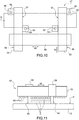
- the manipulator 44 comprises a base 45, a system of articulated arms 46 that are connected to each other and to the base 45, and a gripping unit 47 attached to the arms 46.
- the unit 47 comprises, in turn, an elongated support cross member 48, which extends in a direction 49 and is rotatably coupled to the arms 46 so as to rotate, with respect to the arms 46, around a rotation axis 50 parallel to a direction 51 transverse to direction 49.
- the orientation of the axis 50 depends on the position of the arms 46 and is preferably, but not necessarily, perpendicular to the surface P.
- the unit 47 further comprises two slides 52 slidably coupled to the cross member 48 so that they can move relative to one another along the cross member 48 in direction 49, and two elongated arms 53, which extend in a direction 54 orthogonal to directions 49 and 51 and are mounted on the slides 52 through the interposition of respective shock absorber devices 55.
- Each arm 53 extends on opposite sides of the cross member 48 in direction 54 and is provided with a plurality of suction cups 56, which are connected to a known, not shown, pneumatic suction device and are designed to hold an upper face of the component C or of a stack of overlapping components C.
- Each arm 53 is further delimited by two opposite side faces 57, 58, with the face 57 facing the face 57 of the other arm 53.
- Each face 57, 58 supports a respective pushing device 59, which is slidably coupled to the corresponding arm 53 to move rectilinearly along the corresponding arm 53 in direction 54 independently of the other devices 59.
- the devices 59 mounted on the faces 57 are fixed in direction 54, and the devices 59 mounted on the faces 58 are movable in direction 54, or vice versa.
- Each device 59 is provided with a pushing pin 60 ( Figures 10 and 11 ), which is movable in direction 51 between a retracted rest position and at least one extracted operating position.
- the simultaneous use of the four pushing devices 59 allows the manipulator 44 to correctly position each component C between the pins 60 in direction 54 and to feed it correctly to the main pusher 21 or the secondary pusher 22 or against the end-of-travel device 38 or the end-of-travel device 40.
- the simultaneous use of the four pushing devices 59 allows the manipulator 44 to correctly position and feed a stack of overlapping components C, which are firstly positioned correctly between the pins 60 and then moved on the surface P by the manipulator 44 by combining the action of the suction cups 56 with the action of the pins 60.
- each pin 60 is selectively movable in a plurality of extracted operating positions as a function of a height of the component C or of the stack of components C.
- each pin 60 is eliminated and replaced with a support element, which is L-shaped, comprises a support base for a component C or a stack of components C, and is mounted so as to rotate between an operating position, in which the support base is arranged under the component C or the stack of components C so as to allow the unit 47 to lift the component C or the stack of components C from the surface P, and a rest position, in which the support base disengages the component C or the stack of components C so as to allow the unit 47 to move the component C or the stack of components C on the surface P.
- a support element which is L-shaped, comprises a support base for a component C or a stack of components C, and is mounted so as to rotate between an operating position, in which the support base is arranged under the component C or the stack of components C so as to allow the unit 47 to lift the component C or the stack of components C from the surface P, and a rest position, in which the support base disengages the component C or the stack of components C so as to allow the unit 47 to move the component C
- each pin 60 is eliminated and replaced with a pin provided with a support base, which is movable between the aforementioned operating and rest positions.
- machine 1 has some further advantages mainly due to the fact that:
Landscapes
- Engineering & Computer Science (AREA)
- Mechanical Engineering (AREA)
- Robotics (AREA)
- Life Sciences & Earth Sciences (AREA)
- Wood Science & Technology (AREA)
- Forests & Forestry (AREA)
- De-Stacking Of Articles (AREA)
- Securing Of Glass Panes Or The Like (AREA)
- Sawing (AREA)
Applications Claiming Priority (1)
| Application Number | Priority Date | Filing Date | Title |
|---|---|---|---|
| IT102018000010039A IT201800010039A1 (it) | 2018-11-05 | 2018-11-05 | Macchina sezionatrice per il taglio di pannelli di legno o simili |
Publications (2)
| Publication Number | Publication Date |
|---|---|
| EP3647004A1 true EP3647004A1 (de) | 2020-05-06 |
| EP3647004B1 EP3647004B1 (de) | 2022-09-07 |
Family
ID=65496825
Family Applications (1)
| Application Number | Title | Priority Date | Filing Date |
|---|---|---|---|
| EP19207201.5A Revoked EP3647004B1 (de) | 2018-11-05 | 2019-11-05 | Maschine zum aufteilen von platten aus holz oder dergleichen |
Country Status (2)
| Country | Link |
|---|---|
| EP (1) | EP3647004B1 (de) |
| IT (1) | IT201800010039A1 (de) |
Cited By (2)
| Publication number | Priority date | Publication date | Assignee | Title |
|---|---|---|---|---|
| IT202100027578A1 (it) * | 2021-10-27 | 2023-04-27 | Tic Tac Srl | Processo ed impianto per la lavorazione di pannelli stampabili |
| EP4353432A1 (de) * | 2022-10-12 | 2024-04-17 | IMA Schelling Austria GmbH | Plattenaufteilanlage |
Families Citing this family (8)
| Publication number | Priority date | Publication date | Assignee | Title |
|---|---|---|---|---|
| IT202200020901A1 (it) | 2022-10-11 | 2024-04-11 | Scm Group Spa | Macchina robotizzata e dispositivo manipolatore. |
| IT202200021384A1 (it) | 2022-10-18 | 2024-04-18 | Scm Group Spa | Macchina levigatrice per la lavorazione di pezzi comprendente un dispositivo di regolazione di un componente di levigatura. |
| DE202023104430U1 (de) | 2023-08-04 | 2024-11-05 | Ima Schelling Deutschland Gmbh | Plattenaufteilanordnung |
| IT202300023613A1 (it) | 2023-11-09 | 2025-05-09 | Valter Naldi | Macchina sezionatrice di pannelli |
| IT202300023628A1 (it) | 2023-11-09 | 2025-05-09 | Valter Naldi | Macchina sezionatrice e metodo per la sezionatura di pannelli |
| IT202300023604A1 (it) | 2023-11-09 | 2025-05-09 | Valter Naldi | Macchina sezionatrice |
| IT202300023619A1 (it) | 2023-11-09 | 2025-05-09 | Valter Naldi | Macchina sezionatrice e metodo per la sezionatura di pannelli |
| EP4552777A1 (de) | 2023-11-09 | 2025-05-14 | Valter Naldi | Schneidemaschine und zugehörige betriebsverfahren |
Citations (2)
| Publication number | Priority date | Publication date | Assignee | Title |
|---|---|---|---|---|
| EP2832507A1 (de) * | 2013-07-29 | 2015-02-04 | Schelling Anlagenbau GmbH | Verfahren zum Zersägen von Werkstücken |
| EP3533572A1 (de) | 2018-02-21 | 2019-09-04 | HOMAG Plattenaufteiltechnik GmbH | Plattenaufteilanlage sowie verfahren zum betreiben einer plattenaufteilanlage |
Family Cites Families (10)
| Publication number | Priority date | Publication date | Assignee | Title |
|---|---|---|---|---|
| DE3320762C2 (de) | 1983-06-09 | 1994-10-27 | Trumpf Gmbh & Co | Stanzmaschine mit einem stationären Magazin |
| JPH0453914Y2 (de) | 1986-09-16 | 1992-12-17 | ||
| JPH07206211A (ja) | 1994-01-17 | 1995-08-08 | Toyota Motor Corp | 搬送装置 |
| DE29902968U1 (de) | 1999-02-19 | 1999-07-15 | Demel, Erhard, 42781 Haan | Greifvorrichtung für einen Roboter |
| EP1208933A1 (de) | 2000-11-21 | 2002-05-29 | Giben Scandinavia A/S | System zur Verarbeitung von plattenförmigen Holzteilen mit Roboter zur Behandlung von einer oder mehreren Platten |
| US7409812B2 (en) | 2006-06-29 | 2008-08-12 | Smart Motion Robotics, Inc. | Robotic packaging device and method |
| US7967354B2 (en) | 2008-05-06 | 2011-06-28 | Fanuc Robotics America, Inc. | Mixed size product handling end of arm tool |
| DE102008036501B4 (de) | 2008-08-05 | 2015-01-15 | Dürr Somac GmbH | Verfahren zum Betrieb eines Robotergreifers und Robotergreifer |
| DE102014225074A1 (de) | 2014-12-05 | 2016-06-09 | Holzma Plattenaufteiltechnik Gmbh | Plattenaufteilanlage zum Aufteilen von plattenförmigen Werkstücken sowie Verfahren zu deren Betrieb |
| DE102014225073A1 (de) | 2014-12-05 | 2016-06-09 | Holzma Plattenaufteiltechnik Gmbh | Plattenaufteilanlage zum Aufteilen von plattenförmigen Werkstücken, sowie Verfahren zu deren Betrieb |
-
2018
- 2018-11-05 IT IT102018000010039A patent/IT201800010039A1/it unknown
-
2019
- 2019-11-05 EP EP19207201.5A patent/EP3647004B1/de not_active Revoked
Patent Citations (2)
| Publication number | Priority date | Publication date | Assignee | Title |
|---|---|---|---|---|
| EP2832507A1 (de) * | 2013-07-29 | 2015-02-04 | Schelling Anlagenbau GmbH | Verfahren zum Zersägen von Werkstücken |
| EP3533572A1 (de) | 2018-02-21 | 2019-09-04 | HOMAG Plattenaufteiltechnik GmbH | Plattenaufteilanlage sowie verfahren zum betreiben einer plattenaufteilanlage |
Cited By (3)
| Publication number | Priority date | Publication date | Assignee | Title |
|---|---|---|---|---|
| IT202100027578A1 (it) * | 2021-10-27 | 2023-04-27 | Tic Tac Srl | Processo ed impianto per la lavorazione di pannelli stampabili |
| WO2023073523A1 (en) * | 2021-10-27 | 2023-05-04 | Tic Tac Srl | A method and an apparatus for processing of printable panels |
| EP4353432A1 (de) * | 2022-10-12 | 2024-04-17 | IMA Schelling Austria GmbH | Plattenaufteilanlage |
Also Published As
| Publication number | Publication date |
|---|---|
| IT201800010039A1 (it) | 2020-05-05 |
| EP3647004B1 (de) | 2022-09-07 |
Similar Documents
| Publication | Publication Date | Title |
|---|---|---|
| EP3647004B1 (de) | Maschine zum aufteilen von platten aus holz oder dergleichen | |
| CN106925999B (zh) | 一种铝模板一体化加工生产线 | |
| EP3533572B1 (de) | Plattenaufteilanlage sowie verfahren zum betreiben einer plattenaufteilanlage | |
| CN100462210C (zh) | 全自动纵横平张式切纸机 | |
| ITMI942230A1 (it) | "maccina utensile per la lavorazione di pannelli e lastre. " | |
| EP2067586A2 (de) | Holzbearbeitungsmaschine | |
| EP3061582B1 (de) | Maschine zum schneiden von tafeln aus holz oder dergleichen | |
| US20200316665A1 (en) | Tool storage system, production plant and method for manipulating with such a tool storage system | |
| EP2540429B1 (de) | Schneidanlage zum Schneiden von Holzplatten und dergleichen. | |
| EP2990147B1 (de) | Vorrichtung zum schneiden von holzplatten oder dergleichen | |
| EP3639958B1 (de) | Maschine zum aufteilen von platten aus holz oder dergleichen | |
| CN211614466U (zh) | 一种有效提高加工精度的剪板机 | |
| EP2801430B1 (de) | Maschine zum Aufteilen von Holzplatten oder dergleichen | |
| CN100396395C (zh) | 用于加工板状工件的机械装置 | |
| CN209038654U (zh) | 取纸臂 | |
| EP3639994B1 (de) | Maschine zum aufteilen von platten aus holz oder dergleichen | |
| EP3639957B1 (de) | Maschine zum aufteilen von platten aus holz oder dergleichen | |
| CN109013793B (zh) | 一种钣金折边生产线 | |
| EP3012053B1 (de) | Maschine zum schneiden von platten aus holz, kunststoff oder dergleichen | |
| CN206751857U (zh) | 一种数控内外油边机 | |
| EP2982467A1 (de) | Vorrichtung zum schneiden von holzplatten oder dergleichen | |
| CN110803494A (zh) | 工件校正系统 | |
| EP2246165A2 (de) | Holz oder änlichen Materialen Bearbeitungsmachine | |
| EP2275238B1 (de) | Maschine für das Schneiden von Holzpaneelen oder Paneelen aus ähnlichem Material | |
| EP4653154A1 (de) | Verfahren zur handhabung von platten aus holz |
Legal Events
| Date | Code | Title | Description |
|---|---|---|---|
| PUAI | Public reference made under article 153(3) epc to a published international application that has entered the european phase |
Free format text: ORIGINAL CODE: 0009012 |
|
| STAA | Information on the status of an ep patent application or granted ep patent |
Free format text: STATUS: THE APPLICATION HAS BEEN PUBLISHED |
|
| AK | Designated contracting states |
Kind code of ref document: A1 Designated state(s): AL AT BE BG CH CY CZ DE DK EE ES FI FR GB GR HR HU IE IS IT LI LT LU LV MC MK MT NL NO PL PT RO RS SE SI SK SM TR |
|
| AX | Request for extension of the european patent |
Extension state: BA ME |
|
| STAA | Information on the status of an ep patent application or granted ep patent |
Free format text: STATUS: REQUEST FOR EXAMINATION WAS MADE |
|
| 17P | Request for examination filed |
Effective date: 20201105 |
|
| RBV | Designated contracting states (corrected) |
Designated state(s): AL AT BE BG CH CY CZ DE DK EE ES FI FR GB GR HR HU IE IS IT LI LT LU LV MC MK MT NL NO PL PT RO RS SE SI SK SM TR |
|
| GRAP | Despatch of communication of intention to grant a patent |
Free format text: ORIGINAL CODE: EPIDOSNIGR1 |
|
| STAA | Information on the status of an ep patent application or granted ep patent |
Free format text: STATUS: GRANT OF PATENT IS INTENDED |
|
| GRAJ | Information related to disapproval of communication of intention to grant by the applicant or resumption of examination proceedings by the epo deleted |
Free format text: ORIGINAL CODE: EPIDOSDIGR1 |
|
| STAA | Information on the status of an ep patent application or granted ep patent |
Free format text: STATUS: REQUEST FOR EXAMINATION WAS MADE |
|
| TPAC | Observations filed by third parties |
Free format text: ORIGINAL CODE: EPIDOSNTIPA |
|
| INTG | Intention to grant announced |
Effective date: 20220125 |
|
| GRAP | Despatch of communication of intention to grant a patent |
Free format text: ORIGINAL CODE: EPIDOSNIGR1 |
|
| STAA | Information on the status of an ep patent application or granted ep patent |
Free format text: STATUS: GRANT OF PATENT IS INTENDED |
|
| INTC | Intention to grant announced (deleted) | ||
| INTG | Intention to grant announced |
Effective date: 20220302 |
|
| GRAS | Grant fee paid |
Free format text: ORIGINAL CODE: EPIDOSNIGR3 |
|
| RAP3 | Party data changed (applicant data changed or rights of an application transferred) |
Owner name: BIESSE S.P.A. |
|
| GRAA | (expected) grant |
Free format text: ORIGINAL CODE: 0009210 |
|
| STAA | Information on the status of an ep patent application or granted ep patent |
Free format text: STATUS: THE PATENT HAS BEEN GRANTED |
|
| AK | Designated contracting states |
Kind code of ref document: B1 Designated state(s): AL AT BE BG CH CY CZ DE DK EE ES FI FR GB GR HR HU IE IS IT LI LT LU LV MC MK MT NL NO PL PT RO RS SE SI SK SM TR |
|
| REG | Reference to a national code |
Ref country code: GB Ref legal event code: FG4D |
|
| REG | Reference to a national code |
Ref country code: CH Ref legal event code: EP Ref country code: AT Ref legal event code: REF Ref document number: 1516657 Country of ref document: AT Kind code of ref document: T Effective date: 20220915 |
|
| REG | Reference to a national code |
Ref country code: DE Ref legal event code: R096 Ref document number: 602019019200 Country of ref document: DE |
|
| REG | Reference to a national code |
Ref country code: IE Ref legal event code: FG4D |
|
| REG | Reference to a national code |
Ref country code: LT Ref legal event code: MG9D |
|
| REG | Reference to a national code |
Ref country code: NL Ref legal event code: MP Effective date: 20220907 |
|
| PG25 | Lapsed in a contracting state [announced via postgrant information from national office to epo] |
Ref country code: SE Free format text: LAPSE BECAUSE OF FAILURE TO SUBMIT A TRANSLATION OF THE DESCRIPTION OR TO PAY THE FEE WITHIN THE PRESCRIBED TIME-LIMIT Effective date: 20220907 Ref country code: RS Free format text: LAPSE BECAUSE OF FAILURE TO SUBMIT A TRANSLATION OF THE DESCRIPTION OR TO PAY THE FEE WITHIN THE PRESCRIBED TIME-LIMIT Effective date: 20220907 Ref country code: NO Free format text: LAPSE BECAUSE OF FAILURE TO SUBMIT A TRANSLATION OF THE DESCRIPTION OR TO PAY THE FEE WITHIN THE PRESCRIBED TIME-LIMIT Effective date: 20221207 Ref country code: LV Free format text: LAPSE BECAUSE OF FAILURE TO SUBMIT A TRANSLATION OF THE DESCRIPTION OR TO PAY THE FEE WITHIN THE PRESCRIBED TIME-LIMIT Effective date: 20220907 Ref country code: LT Free format text: LAPSE BECAUSE OF FAILURE TO SUBMIT A TRANSLATION OF THE DESCRIPTION OR TO PAY THE FEE WITHIN THE PRESCRIBED TIME-LIMIT Effective date: 20220907 Ref country code: FI Free format text: LAPSE BECAUSE OF FAILURE TO SUBMIT A TRANSLATION OF THE DESCRIPTION OR TO PAY THE FEE WITHIN THE PRESCRIBED TIME-LIMIT Effective date: 20220907 |
|
| PG25 | Lapsed in a contracting state [announced via postgrant information from national office to epo] |
Ref country code: HR Free format text: LAPSE BECAUSE OF FAILURE TO SUBMIT A TRANSLATION OF THE DESCRIPTION OR TO PAY THE FEE WITHIN THE PRESCRIBED TIME-LIMIT Effective date: 20220907 Ref country code: GR Free format text: LAPSE BECAUSE OF FAILURE TO SUBMIT A TRANSLATION OF THE DESCRIPTION OR TO PAY THE FEE WITHIN THE PRESCRIBED TIME-LIMIT Effective date: 20221208 |
|
| PG25 | Lapsed in a contracting state [announced via postgrant information from national office to epo] |
Ref country code: SM Free format text: LAPSE BECAUSE OF FAILURE TO SUBMIT A TRANSLATION OF THE DESCRIPTION OR TO PAY THE FEE WITHIN THE PRESCRIBED TIME-LIMIT Effective date: 20220907 Ref country code: RO Free format text: LAPSE BECAUSE OF FAILURE TO SUBMIT A TRANSLATION OF THE DESCRIPTION OR TO PAY THE FEE WITHIN THE PRESCRIBED TIME-LIMIT Effective date: 20220907 Ref country code: PT Free format text: LAPSE BECAUSE OF FAILURE TO SUBMIT A TRANSLATION OF THE DESCRIPTION OR TO PAY THE FEE WITHIN THE PRESCRIBED TIME-LIMIT Effective date: 20230109 Ref country code: ES Free format text: LAPSE BECAUSE OF FAILURE TO SUBMIT A TRANSLATION OF THE DESCRIPTION OR TO PAY THE FEE WITHIN THE PRESCRIBED TIME-LIMIT Effective date: 20220907 Ref country code: CZ Free format text: LAPSE BECAUSE OF FAILURE TO SUBMIT A TRANSLATION OF THE DESCRIPTION OR TO PAY THE FEE WITHIN THE PRESCRIBED TIME-LIMIT Effective date: 20220907 |
|
| PG25 | Lapsed in a contracting state [announced via postgrant information from national office to epo] |
Ref country code: SK Free format text: LAPSE BECAUSE OF FAILURE TO SUBMIT A TRANSLATION OF THE DESCRIPTION OR TO PAY THE FEE WITHIN THE PRESCRIBED TIME-LIMIT Effective date: 20220907 Ref country code: PL Free format text: LAPSE BECAUSE OF FAILURE TO SUBMIT A TRANSLATION OF THE DESCRIPTION OR TO PAY THE FEE WITHIN THE PRESCRIBED TIME-LIMIT Effective date: 20220907 Ref country code: IS Free format text: LAPSE BECAUSE OF FAILURE TO SUBMIT A TRANSLATION OF THE DESCRIPTION OR TO PAY THE FEE WITHIN THE PRESCRIBED TIME-LIMIT Effective date: 20230107 Ref country code: EE Free format text: LAPSE BECAUSE OF FAILURE TO SUBMIT A TRANSLATION OF THE DESCRIPTION OR TO PAY THE FEE WITHIN THE PRESCRIBED TIME-LIMIT Effective date: 20220907 |
|
| REG | Reference to a national code |
Ref country code: DE Ref legal event code: R026 Ref document number: 602019019200 Country of ref document: DE |
|
| PLBI | Opposition filed |
Free format text: ORIGINAL CODE: 0009260 |
|
| PLAX | Notice of opposition and request to file observation + time limit sent |
Free format text: ORIGINAL CODE: EPIDOSNOBS2 |
|
| PG25 | Lapsed in a contracting state [announced via postgrant information from national office to epo] |
Ref country code: NL Free format text: LAPSE BECAUSE OF FAILURE TO SUBMIT A TRANSLATION OF THE DESCRIPTION OR TO PAY THE FEE WITHIN THE PRESCRIBED TIME-LIMIT Effective date: 20220907 Ref country code: MC Free format text: LAPSE BECAUSE OF FAILURE TO SUBMIT A TRANSLATION OF THE DESCRIPTION OR TO PAY THE FEE WITHIN THE PRESCRIBED TIME-LIMIT Effective date: 20220907 Ref country code: AL Free format text: LAPSE BECAUSE OF FAILURE TO SUBMIT A TRANSLATION OF THE DESCRIPTION OR TO PAY THE FEE WITHIN THE PRESCRIBED TIME-LIMIT Effective date: 20220907 |
|
| REG | Reference to a national code |
Ref country code: CH Ref legal event code: PL |
|
| 26 | Opposition filed |
Opponent name: DUERR AKTIENGESELLSCHAFT Effective date: 20230605 |
|
| REG | Reference to a national code |
Ref country code: BE Ref legal event code: MM Effective date: 20221130 |
|
| PG25 | Lapsed in a contracting state [announced via postgrant information from national office to epo] |
Ref country code: LI Free format text: LAPSE BECAUSE OF NON-PAYMENT OF DUE FEES Effective date: 20221130 Ref country code: DK Free format text: LAPSE BECAUSE OF FAILURE TO SUBMIT A TRANSLATION OF THE DESCRIPTION OR TO PAY THE FEE WITHIN THE PRESCRIBED TIME-LIMIT Effective date: 20220907 Ref country code: CH Free format text: LAPSE BECAUSE OF NON-PAYMENT OF DUE FEES Effective date: 20221130 |
|
| REG | Reference to a national code |
Ref country code: AT Ref legal event code: UEP Ref document number: 1516657 Country of ref document: AT Kind code of ref document: T Effective date: 20220907 |
|
| PG25 | Lapsed in a contracting state [announced via postgrant information from national office to epo] |
Ref country code: SI Free format text: LAPSE BECAUSE OF FAILURE TO SUBMIT A TRANSLATION OF THE DESCRIPTION OR TO PAY THE FEE WITHIN THE PRESCRIBED TIME-LIMIT Effective date: 20220907 Ref country code: LU Free format text: LAPSE BECAUSE OF NON-PAYMENT OF DUE FEES Effective date: 20221105 |
|
| PG25 | Lapsed in a contracting state [announced via postgrant information from national office to epo] |
Ref country code: IE Free format text: LAPSE BECAUSE OF NON-PAYMENT OF DUE FEES Effective date: 20221105 |
|
| PG25 | Lapsed in a contracting state [announced via postgrant information from national office to epo] |
Ref country code: FR Free format text: LAPSE BECAUSE OF NON-PAYMENT OF DUE FEES Effective date: 20221107 Ref country code: BE Free format text: LAPSE BECAUSE OF NON-PAYMENT OF DUE FEES Effective date: 20221130 |
|
| PGFP | Annual fee paid to national office [announced via postgrant information from national office to epo] |
Ref country code: IT Payment date: 20231102 Year of fee payment: 5 Ref country code: DE Payment date: 20231127 Year of fee payment: 5 |
|
| PG25 | Lapsed in a contracting state [announced via postgrant information from national office to epo] |
Ref country code: HU Free format text: LAPSE BECAUSE OF FAILURE TO SUBMIT A TRANSLATION OF THE DESCRIPTION OR TO PAY THE FEE WITHIN THE PRESCRIBED TIME-LIMIT; INVALID AB INITIO Effective date: 20191105 |
|
| PG25 | Lapsed in a contracting state [announced via postgrant information from national office to epo] |
Ref country code: CY Free format text: LAPSE BECAUSE OF FAILURE TO SUBMIT A TRANSLATION OF THE DESCRIPTION OR TO PAY THE FEE WITHIN THE PRESCRIBED TIME-LIMIT Effective date: 20220907 |
|
| PG25 | Lapsed in a contracting state [announced via postgrant information from national office to epo] |
Ref country code: MK Free format text: LAPSE BECAUSE OF FAILURE TO SUBMIT A TRANSLATION OF THE DESCRIPTION OR TO PAY THE FEE WITHIN THE PRESCRIBED TIME-LIMIT Effective date: 20220907 |
|
| RDAF | Communication despatched that patent is revoked |
Free format text: ORIGINAL CODE: EPIDOSNREV1 |
|
| REG | Reference to a national code |
Ref country code: DE Ref legal event code: R103 Ref document number: 602019019200 Country of ref document: DE Ref country code: DE Ref legal event code: R064 Ref document number: 602019019200 Country of ref document: DE |
|
| GBPC | Gb: european patent ceased through non-payment of renewal fee |
Effective date: 20231105 |
|
| PG25 | Lapsed in a contracting state [announced via postgrant information from national office to epo] |
Ref country code: BG Free format text: LAPSE BECAUSE OF FAILURE TO SUBMIT A TRANSLATION OF THE DESCRIPTION OR TO PAY THE FEE WITHIN THE PRESCRIBED TIME-LIMIT Effective date: 20220907 |
|
| RDAG | Patent revoked |
Free format text: ORIGINAL CODE: 0009271 |
|
| STAA | Information on the status of an ep patent application or granted ep patent |
Free format text: STATUS: PATENT REVOKED |
|
| PG25 | Lapsed in a contracting state [announced via postgrant information from national office to epo] |
Ref country code: MT Free format text: LAPSE BECAUSE OF FAILURE TO SUBMIT A TRANSLATION OF THE DESCRIPTION OR TO PAY THE FEE WITHIN THE PRESCRIBED TIME-LIMIT Effective date: 20220907 |
|
| REG | Reference to a national code |
Ref country code: CH Ref legal event code: PL |
|
| PG25 | Lapsed in a contracting state [announced via postgrant information from national office to epo] |
Ref country code: GB Free format text: LAPSE BECAUSE OF NON-PAYMENT OF DUE FEES Effective date: 20231105 |
|
| 27W | Patent revoked |
Effective date: 20240610 |
|
| PG25 | Lapsed in a contracting state [announced via postgrant information from national office to epo] |
Ref country code: GB Free format text: LAPSE BECAUSE OF NON-PAYMENT OF DUE FEES Effective date: 20231105 |
|
| REG | Reference to a national code |
Ref country code: AT Ref legal event code: MA03 Ref document number: 1516657 Country of ref document: AT Kind code of ref document: T Effective date: 20240610 |
|
| PG25 | Lapsed in a contracting state [announced via postgrant information from national office to epo] |
Ref country code: TR Free format text: LAPSE BECAUSE OF FAILURE TO SUBMIT A TRANSLATION OF THE DESCRIPTION OR TO PAY THE FEE WITHIN THE PRESCRIBED TIME-LIMIT Effective date: 20220907 |
|
| PGFP | Annual fee paid to national office [announced via postgrant information from national office to epo] |
Ref country code: AT Payment date: 20260410 Year of fee payment: 5 |