EP3647018B1 - Form zur räumlichen formgebung von kunststoffteilen aus hdpe oder pa oder ähnlichen kunststoffen, insbesondere hdpe- oder pa-rohre - Google Patents
Form zur räumlichen formgebung von kunststoffteilen aus hdpe oder pa oder ähnlichen kunststoffen, insbesondere hdpe- oder pa-rohre Download PDFInfo
- Publication number
- EP3647018B1 EP3647018B1 EP18204109.5A EP18204109A EP3647018B1 EP 3647018 B1 EP3647018 B1 EP 3647018B1 EP 18204109 A EP18204109 A EP 18204109A EP 3647018 B1 EP3647018 B1 EP 3647018B1
- Authority
- EP
- European Patent Office
- Prior art keywords
- mould
- hdpe
- labyrinth
- shaping
- tube
- Prior art date
- Legal status (The legal status is an assumption and is not a legal conclusion. Google has not performed a legal analysis and makes no representation as to the accuracy of the status listed.)
- Active
Links
Images


Classifications
-
- B—PERFORMING OPERATIONS; TRANSPORTING
- B29—WORKING OF PLASTICS; WORKING OF SUBSTANCES IN A PLASTIC STATE IN GENERAL
- B29C—SHAPING OR JOINING OF PLASTICS; SHAPING OF MATERIAL IN A PLASTIC STATE, NOT OTHERWISE PROVIDED FOR; AFTER-TREATMENT OF THE SHAPED PRODUCTS, e.g. REPAIRING
- B29C53/00—Shaping by bending, folding, twisting, straightening or flattening; Apparatus therefor
- B29C53/02—Bending or folding
- B29C53/08—Bending or folding of tubes or other profiled members
- B29C53/083—Bending or folding of tubes or other profiled members bending longitudinally, i.e. modifying the curvature of the tube axis
-
- B—PERFORMING OPERATIONS; TRANSPORTING
- B29—WORKING OF PLASTICS; WORKING OF SUBSTANCES IN A PLASTIC STATE IN GENERAL
- B29C—SHAPING OR JOINING OF PLASTICS; SHAPING OF MATERIAL IN A PLASTIC STATE, NOT OTHERWISE PROVIDED FOR; AFTER-TREATMENT OF THE SHAPED PRODUCTS, e.g. REPAIRING
- B29C33/00—Moulds or cores; Details thereof or accessories therefor
- B29C33/42—Moulds or cores; Details thereof or accessories therefor characterised by the shape of the moulding surface, e.g. ribs or grooves
-
- B—PERFORMING OPERATIONS; TRANSPORTING
- B29—WORKING OF PLASTICS; WORKING OF SUBSTANCES IN A PLASTIC STATE IN GENERAL
- B29C—SHAPING OR JOINING OF PLASTICS; SHAPING OF MATERIAL IN A PLASTIC STATE, NOT OTHERWISE PROVIDED FOR; AFTER-TREATMENT OF THE SHAPED PRODUCTS, e.g. REPAIRING
- B29C33/00—Moulds or cores; Details thereof or accessories therefor
- B29C33/38—Moulds or cores; Details thereof or accessories therefor characterised by the material or the manufacturing process
-
- B—PERFORMING OPERATIONS; TRANSPORTING
- B29—WORKING OF PLASTICS; WORKING OF SUBSTANCES IN A PLASTIC STATE IN GENERAL
- B29K—INDEXING SCHEME ASSOCIATED WITH SUBCLASSES B29B, B29C OR B29D, RELATING TO MOULDING MATERIALS OR TO MATERIALS FOR MOULDS, REINFORCEMENTS, FILLERS OR PREFORMED PARTS, e.g. INSERTS
- B29K2023/00—Use of polyalkenes or derivatives thereof as moulding material
- B29K2023/04—Polymers of ethylene
- B29K2023/06—PE, i.e. polyethylene
- B29K2023/0608—PE, i.e. polyethylene characterised by its density
- B29K2023/065—HDPE, i.e. high density polyethylene
-
- B—PERFORMING OPERATIONS; TRANSPORTING
- B29—WORKING OF PLASTICS; WORKING OF SUBSTANCES IN A PLASTIC STATE IN GENERAL
- B29K—INDEXING SCHEME ASSOCIATED WITH SUBCLASSES B29B, B29C OR B29D, RELATING TO MOULDING MATERIALS OR TO MATERIALS FOR MOULDS, REINFORCEMENTS, FILLERS OR PREFORMED PARTS, e.g. INSERTS
- B29K2077/00—Use of PA, i.e. polyamides, e.g. polyesteramides or derivatives thereof, as moulding material
-
- B—PERFORMING OPERATIONS; TRANSPORTING
- B29—WORKING OF PLASTICS; WORKING OF SUBSTANCES IN A PLASTIC STATE IN GENERAL
- B29K—INDEXING SCHEME ASSOCIATED WITH SUBCLASSES B29B, B29C OR B29D, RELATING TO MOULDING MATERIALS OR TO MATERIALS FOR MOULDS, REINFORCEMENTS, FILLERS OR PREFORMED PARTS, e.g. INSERTS
- B29K2995/00—Properties of moulding materials, reinforcements, fillers, preformed parts or moulds
- B29K2995/0012—Properties of moulding materials, reinforcements, fillers, preformed parts or moulds having particular thermal properties
- B29K2995/0013—Conductive
-
- C—CHEMISTRY; METALLURGY
- C08—ORGANIC MACROMOLECULAR COMPOUNDS; THEIR PREPARATION OR CHEMICAL WORKING-UP; COMPOSITIONS BASED THEREON
- C08L—COMPOSITIONS OF MACROMOLECULAR COMPOUNDS
- C08L23/00—Compositions of homopolymers or copolymers of unsaturated aliphatic hydrocarbons having only one carbon-to-carbon double bond; Compositions of derivatives of such polymers
- C08L23/02—Compositions of homopolymers or copolymers of unsaturated aliphatic hydrocarbons having only one carbon-to-carbon double bond; Compositions of derivatives of such polymers not modified by chemical after-treatment
- C08L23/04—Homopolymers or copolymers of ethene
- C08L23/06—Polyethylene
Definitions
- the invention relates to a mould for the spatial shaping of plastic parts made of HDPE or PA or similar plastics, in particular HDPE or PA tubes which comprises a body, which is provided with at least one contact wall for the contact between the mould with the moulded material, where at least the contact wall is made of a material having with a thermal conductivity lower than 5 W.m -1 .K -1 .
- HDPE high-density polyethylene
- HDPE high-density polyethylene
- This material is temperature resistant in the range of -50°C to +110°C, as well as chemical resistant, odourless and suitable for direct contact with food. In addition, it is non-toxic and recyclable.
- a wide range of products - parts, including products with a complex spatial structure and shape, are made of HDPE, using plastic injection moulding technologies, foil-making technologies, blowing and extrusion technologies.
- the results of the manufacturing process are finished products, such as three-dimensional objects made by plastic injection moulding, foils, tubes, rods, etc. Similar is the case with PA and other plastics.
- plastic is used in the form of granules, powders or tablets. Products made of these plastics, such as HDPE, PA and others, are thus made directly, obtaining the final shape at once, and secondary shaping is not generally applied. Alternatively, welding or bonding of simpler parts to form the final product can be applied. In the case of special products, such as spatially shaped tubes and other longitudinal products, etc., it is necessary to have special equipment for the production of these products, which is very costly and its operation is rather demanding.
- the moulds used for this purpose are made either of steel or of another metal with a high temperature thermal conductivity, with steel having a thermal conductivity ⁇ 20 of about 50 W.m -1 .K -1 . It is apparent that such bent tubes are made of a special elastic material which exhibits the required mechanical properties before moulding, i.e. before heating, as well as after moulding, i.e., after heating and cooling.
- hot steam In the case of hot steam shaping (bending), hot steam the temperature of which is usually in the range of 110 ° C to 140 ° C is fed into the inner space of the shaped tube.
- the material of the shaped tube As a result of heating the material of the shaped tube by this steam, the material of the shaped tube is brought into a plastic state in which, due to the stresses induced by inserting the shaped tube into the shaped form of the labyrinth made of steel or another metal, the originally straight tube is only elastically deformed and changes its shape, that is to say, it acquires the desired resulting and permanent shape of the bent tube.
- the steam supply is disconnected and the shaped tube is cooled, by which means the shape of the shaped tube is fixed in this state.
- a resilient body e.g., a spring
- the elastic tube is inserted into the labyrinth (bending mould), whereby by one of its ends it is inserted into the cavity of a stopper head arranged at one end of the labyrinth.
- the subsequent process consists in heating the shaped tube in the furnace to a plastic state, the heating temperature being in the range of 120 ° C to 220 ° C.
- the heating temperature being in the range of 120 ° C to 220 ° C.
- EP application No. 18182428.5 discloses a method and device for shaping products made of HDPE or PA, in particular the HDPE or PA tube spatial shaping, in which HDPE or PA semi-finished product is shaped such that HDPE or the PA preform is first heated to a temperature T close to the melting temperature T g of the material such that the material is still in a solid state. At this temperature T the HDPE or PA semi-finished product is left for a time period t 1 , which is necessary for the semi-product to obtain plasticity, to disrupt completely or partially the crystalline or semi-crystalline structure of the HDPE or PA material and to return the material to an amorphous or partially amorphous state.
- the HDPE or PA semi-finished product is inserted into a shaping fixture and the temperature of the HDPE or PA material is gradually reduced to ambient temperature in order to recover the crystalline or semicrystalline structure and to relax the internal stresses of the HDPE or PA material, so that the shape of the shaped material after complete cooling down and removal from the mould is maintained.
- An ideal method for cooling the shaped part is gradual cooling by means of a tempering furnace for a certain time period at the tempering temperature required to restore or partially restore the crystalline or semicrystalline structure and to relax the internal stresses of HDPE or PA material.
- the HDPE or PA material is freely cooled by air and, if appropriate, it is cooled with a cooling medium, whereupon the HDPE or PA material is removed from the shaping fixture as a finished product from HDPE or PA.
- This option is reliable but requires the use of a tempering furnace, which limits productivity and increases costs.
- the HDPE or PA material is freely cooled by air and, if appropriate, it is cooled with a cooling medium, whereupon the HDPE or PA material must be left in the shaping fixture at normal room temperature for the time required for the shape stabilization of HDPE or PA material, and it is possible only then to remove the HDPE or PA shaped part from the shaping fixture.
- This variant extends the time needed to leave the workpiece in the mould, reduces productivity and increases costs.
- GB 1 589 667 describes a device and a method for shaping foam tubes for thermal insulation of heating or cooling distribution systems.
- a straight foam tube with its longitudinal cavity, is drawn onto the outer circumference of a bent inner mould, which is formed by a bent metal tube.
- the straight foam tube attains the shape of the shaped foam tube.
- the bent inner mould is provided with a perforation for sucking air into the inner space of the inner mould through the foam material of the shaped foam tube. Consequently, the shaped foam tube is sucked by its inner surface onto the outer surface of the inner mould and copies its outer shape.
- the ends of the shaped foam tube are sealed, for example, by sleeves or rubber sealing discs or conical receptacles.
- the inner mould is provided in the bent section with a longitudinal slot for guiding a knife or another cutting tool to cut the foam material of the shaped foam tube in the bent section to prevent tearing the shaped foam tube during its removal from the inner mould.
- the inner mould is coated with lacquers or another appropriate material reducing adhesion of the foam material of the shaped foam tube to the inner mould.
- GB 1 589 667 also describes that the foam tube is drawn onto the inner mould, the ends and of the shaped foam tube are sealed and the whole assembly is heated (in a furnace, at a source of heating, etc.) until the foam material of the shaped foam tube attains a plasticized conditions.
- the inner space of the inner mould is connected to vacuum (or under pressure) to suck the foam tube onto the inner mould.
- the foam tube is cooled down, optionally with the use of an external cooling medium or even a cooling medium circulating through the inner cavity of the inner mould. Subsequently, the foam tube is removed by slipping off the inner mould.
- GB 1 589 667 leads only to the insertion of an inner mould (tube) into the inner cavity of the shaped tube, which is, for example, completely impossible when shaping long and spatially complex tubes.
- US 3 562 860 A describes a device for shaping plastic tubes, especially for creating short bends (col. 2, line 17), by inserting thin plates 3 into the shaped tube 7 (optionally closed at one of its ends), which fill the inner space of the shaped tube 7.
- the shaped tube 7 with the end (closed) is inserted to the beginning of the shaping channel in a two-part symmetrical mould 2 just before the bending section of the mould 2.
- the mould 2 is made of wood, plastic or metal, and is provided with integrated heating and cooling means which ensure all the heat treatment of the tube, i.e. heating, cooling and tempering, all this takes place in the mould 2 (col. 2, lines 48 to 60).
- a pressure element 4 presses on the ends of the plates 3 at the other end of the shaped tube 7 and the shaped tube 7 is pressed longitudinally into the bending section of the mould 2 so the tube 7 and inserted plates 3 are bent.
- the mould 2 is opened and the moulded tube 7 is removed, whereupon the plates 3 are removed.
- D2 depends on the connection of each mould 2 to heating, cooling and tempering sources.
- the mould 2 according to US 3 562 860 A is complex and expensive, so that the production rate is low. US 3 562 860 A does not allow to create spatially complex bends of longer tubes. Nowhere does D2 indicate an intentional deceleration of the cooling of the tube 7 in the mould 2 without expending additional energy through channels 6.
- the aim of the invention is therefore to eliminate or at least minimize the disadvantages of the background art, especially to improve productivity and also reduce the costs of the additional shaping of parts made of HDPE or PA tubes or similar plastics, particularly of HDPE or PA tubes.
- the aim of the invention is achieved by a mould for the spatial shaping of plastic parts made of HDPE or PA or similar plastics, in particular of HDPE or PA tubes, whose principle consists in that the contact wall is formed on the shaping labyrinth for shaping tubes, which is formed as a spatially formed tube with a longitudinal cavity, which is provided with a through slot along its length to insert the shaped tube into the labyrinth or is formed as a shaped groove in a body, whereas the shaping labyrinth is adapted to hold the shaped tube in the shaping labyrinth for slow cooling of the product so as to recover or partially recover the crystalline or semicrystalline structure and to relax the internal stresses of HDPE or PA or similar plastics by simply cooling the product in the mould in free air.
- the invention permits replacing a tempering furnace for slow cooling of the product so as to recover or partially recover the crystalline or semicrystalline structure and to relax the internal stresses of HDPE or PA material by simply cooling the product in the mould in free air and at the same time eliminating the need for leaving the product in the shaping fixture (in the mould) at normal room temperature for the time required for the shape stabilization of the HDPE or PA material, thereby achieving comparable results to using a tempering furnace even without the use of a tempering furnace. This also improves productivity by eliminating the need to wait for relaxation of internal stresses at room temperature.
- Fig. 1 an example of a labyrinth for shaping tubes made of HDPE or PA according to the invention to be fastened on a rod holder of a carrier
- Fig. 1a is a sectional view of a labyrinth with a contact surface in the form of a surface layer
- Fig. 1b is a sectional view of a labyrinth with a contact surface which is an integral part of the body of the labyrinth
- Fig. 1c is a cross-section of a labyrinth with a contact wall which is an integral part of the body of the labyrinth which is an integral part of the carrier (see Figure 2 )
- Fig. 1a an example of a labyrinth for shaping tubes made of HDPE or PA according to the invention to be fastened on a rod holder of a carrier
- Fig. 1a is a sectional view of a labyrinth with a contact surface in the form of a surface layer
- Fig. 1d is an example of a labyrinth with holders for fastening on the carrier
- Fig. 1e is an example of a labyrinth fastened by means of holders on the carrier
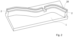
- Fig. is an example of a labyrinth for shaping tubes made of HDPE or PA according to the invention with an integrated carrier.
- a mould or a shaping fixture, for shaping products made of HDPE or PA or similar plastics, in which a pre-prepared product, in fact a semi-finished product, e.g., a straight tube or a multilayer tube, etc., is heated and inserted into a mould and, having been left in the mould for a required period of time, is formed into a desired shape - the resulting product, e.g. spatially shaped (bent) tubes.
- the mould for the spatial shaping of plastic parts made of HDPE or PA or similar plastics comprises a body 1 , in which the shaping labyrinth 2 is formed.
- the mould 1 is formed either as a single or multi-part, and so is the shaping labyrinth 2 .
- the shaping labyrinth 2 has a spatial arrangement corresponding to the desired spatial arrangement of the final product, i.e., in this case the specifically desired resulting spatial shape of the HDPE or PA tube being formed.
- the dimensions of the shaping labyrinth 2 correspond to the dimensions of the shaped tube.
- the shaping labyrinth 2 is formed as a spatially formed tube with a longitudinal cavity which is provided with a through slot along its length to insert the shaped tube into the labyrinth 2 , or the shaping labyrinth 2 is formed as a shaped groove in a suitable body.
- the shaping labyrinth 2 is made by suitable technology, for example, by cutting from a bent tube, by 3D printing, by machining, etc., or by a combination of two or more technologies, etc.
- the mould is further adapted to hold the shaped tube in the shaping labyrinth 2 , for example by means of flaps 3 arranged appropriately along the length of the labyrinth 2 , and despite the presence of the flaps 3 the labyrinth 2 is able to accommodate the shaped tube by inserting a tube from the outside of the labyrinth 2 .
- the shaping labyrinth 2 comprises a contact wall 20 with a shaped tube on its inner side, the contact wall 20 being a functional shape wall 20 of the labyrinth 2 , which is decisive for the future shape of the tube being formed.
- the contact wall 20 of the shaping labyrinth 2 is formed by a coating or insert made of a material with a thermal conductivity lower than 5 W.m -1 .K -1 , more preferably with a thermal conductivity lower than 1 W.m -1 .K -1 , most preferably with a thermal conductivity lower than 0.5 W.m -1 .K -1 .
- the coating or insert is formed by a suitable technology, such as coating, 3D printing, pressing, etc., or by combining at least two different technologies.
- the entire shaping labyrinth 2 is made of a material with a thermal conductivity lower than 5 W.m -1 .K -1 , more preferably with a thermal conductivity lower than 1 W.m -1 .K -1 , most preferably with a thermal conductivity lower than 0.5 W.m -1 .K -1 .
- the labyrinth is made by a suitable technology, such as machining, 3D printing, cutting the shaped tube from a suitable material, etc., or by combining at least two different technologies.
- the shaping labyrinth 2 is provided with fastening means 21 for fastening it on the carrier 4 , which is shown in Fig. 1e .
- Figs. 1 , 1a, 1b , 1d and 1e show a particularly preferred embodiment of a labyrinth 2, wherein the labyrinth 2 is for production simplification divided into sections which are provided with special flanges 22 for joining individual adjacent sections of the labyrinth 2
- the embodiments of the flanges 22 and their principle, however, are not the subject-matter of the present invention.
- the entire mould i.e., including the body 1 and te shaping labyrinth 2 ae made of a material with a thermal conductivity lower than 5 W.m -1 .K -1 , more preferably with a thermal conductivity lower than 1 W.m -1 .K -1 , most preferably with a thermal conductivity lower than 0,5 W.m -1 .K -1 .
- the labyrinth is made by a suitable technology, such as machining, 3D printing, cutting the shaped tube from a suitable material, etc., or by combining at least two different technologies.
- the body 1 and the labyrinth 2 are made by a suitable technology, such as machining, 3D printing, cutting from a suitable material, etc., or by combining at least two different technologies.
- An example of a material with a thermal conductivity lower than 5 W. -1 .K -1 is wood, plastic, especially polymer, reinforced polystyrene, teflon, a composite, especially polymeric matrix composite, etc. From the point of view of the durability of the mould, or, more specifically, its contact walls 20, it is desirable and advantageous if the material used with a thermal conductivity lower than 5 or 1, or 0.5 W.m -1 .K -1 has temperature resistance at least at the level to which a shaped product of HDPE or PA or similar plastics is heated prior to being inserted into the mould according to the present invention.
- the contact walls 20 for the contact with the material being shaped are provided with at least a coating of a material with a thermal conductivity lower than 5 W.m -1 .K -1 , more preferably with a thermal conductivity lower than 1 W.m -1 .K -1 , most preferably with a thermal conductivity lower than 0.5 W.m -1 .K -1 , or the contact walls 20 or part on which the contact walls 20 located are directly made of a material with a thermal conductivity lower than 5 W.m -1 .K -1 , more preferably with a thermal conductivity lower than 1 W.m -1 .K -1 , most preferably with a thermal conductivity lower than 0.5 W.m -1 .K -1 .
- the invention is applicable for series production of products made of HDPE or PA or similar plastics by further shaping of previously produced semi-products. It is particularly advantageous for the spatious shaping of HDPE or PA tubes from HDPE or PA straight tubes.
Landscapes
- Engineering & Computer Science (AREA)
- Mechanical Engineering (AREA)
- Manufacturing & Machinery (AREA)
- Moulds For Moulding Plastics Or The Like (AREA)
- Shaping Of Tube Ends By Bending Or Straightening (AREA)
Claims (4)
- Form zum räumlichen Formen von Kunststoffteilen aus HDPE oder PA oder ähnlichen Kunststoffen, insbesondere Rohren aus HDPE oder PA, die einen Körper (1) aufweist, der mindestens eine Kontaktwand (20) zum Kontakt der Form mit geformtem Material aufweist, wo mindestens die Kontaktwand (20) aus einem Material mit einer Wärmeleitfähigkeit von weniger als 5 W.m-1.K-1 ausgebildet ist, dadurch gekennzeichnet, dass die Kontaktwand (20) an einem Formlabyrinth (2) zum Formen von Rohren ausgebildet ist, das als räumlich geformtes Rohr mit einem Längshohlraum ausgebildet ist, das entlang seiner Länge einen Durchgangsschlitz zum Hineinschieben des geformten Rohrs in das Labyrinth (2) aufweist oder das als räumlich geformte Formnut im Körper ausgebildet ist, wobei das Formlabyrinth (2) die Mittel zum Halten des geformten Rohrs im Formlabyrinth (2) zum verlangsamten Abkühlen des Produkts zum Wiederherstellen oder teilweisen Wiederherstellen der kristallinen oder semikristallinen Struktur und zur Relaxation der inneren Spannung von HDPE oder PA oder ähnlichen Kunststoffen durch einfaches Abkühlen des Produkts in der Form an der frischen Luft aufweist.
- Form nach dem Anspruch 1, dadurch gekennzeichnet, dass die Kontaktwand (20) des Formlabyrinths (2) durch einen Auftrag oder eine Einlage aus einem Material mit einer Wärmeleitfähigkeit von weniger als 5 W.m-1.K-1 gebildet wird.
- Form nach dem Anspruch 1, dadurch gekennzeichnet, dass das Formlabyrinth (2) auch mit dem Körper (1) aus einem Material mit einer Wärmeleitfähigkeit von weniger als 5 W.m-1.K-1 gebildet wird.
- Form nach einem der Ansprüche 1 bis 3, dadurch gekennzeichnet, dass die Mittel zum Halten des geformten Rohrs im Hohlraum des Formlabyrinths (2) durch Lippen (3) gebildet sind, die entlang der Länge des Labyrinths (2) angeordnet sind.
Priority Applications (3)
| Application Number | Priority Date | Filing Date | Title |
|---|---|---|---|
| EP18204109.5A EP3647018B1 (de) | 2018-11-02 | 2018-11-02 | Form zur räumlichen formgebung von kunststoffteilen aus hdpe oder pa oder ähnlichen kunststoffen, insbesondere hdpe- oder pa-rohre |
| US16/278,474 US20200139589A1 (en) | 2018-11-02 | 2019-02-18 | Mould for the Spatial Shaping of Plastic Parts made of HDPE or PA or Similar Plastics, in particular HDPE or PA Tubes |
| MX2019012915A MX2019012915A (es) | 2018-11-02 | 2019-10-30 | Molde para el formado espacial de partes de plastico hechas de hdpe o pa o plasticos similares, en particular tubos de hdpe o pa. |
Applications Claiming Priority (1)
| Application Number | Priority Date | Filing Date | Title |
|---|---|---|---|
| EP18204109.5A EP3647018B1 (de) | 2018-11-02 | 2018-11-02 | Form zur räumlichen formgebung von kunststoffteilen aus hdpe oder pa oder ähnlichen kunststoffen, insbesondere hdpe- oder pa-rohre |
Publications (2)
| Publication Number | Publication Date |
|---|---|
| EP3647018A1 EP3647018A1 (de) | 2020-05-06 |
| EP3647018B1 true EP3647018B1 (de) | 2025-05-14 |
Family
ID=65011718
Family Applications (1)
| Application Number | Title | Priority Date | Filing Date |
|---|---|---|---|
| EP18204109.5A Active EP3647018B1 (de) | 2018-11-02 | 2018-11-02 | Form zur räumlichen formgebung von kunststoffteilen aus hdpe oder pa oder ähnlichen kunststoffen, insbesondere hdpe- oder pa-rohre |
Country Status (3)
| Country | Link |
|---|---|
| US (1) | US20200139589A1 (de) |
| EP (1) | EP3647018B1 (de) |
| MX (1) | MX2019012915A (de) |
Family Cites Families (4)
| Publication number | Priority date | Publication date | Assignee | Title |
|---|---|---|---|---|
| DE1704661B1 (de) * | 1967-11-29 | 1972-05-31 | Hoechst Ag | Verfahren und vorrichtung zum herstellen eines rohrbogens aus thermoplastischem kunststoff |
| DE2638447C3 (de) * | 1976-08-26 | 1981-03-26 | Dynamit Nobel Ag, 5210 Troisdorf | Verfahren und Vorrichtung zur Herstellung von Rohrbögen aus thermoplastischem Schaumstoff zum Isolieren von Rohrleitungen |
| US6540498B1 (en) * | 2001-10-04 | 2003-04-01 | Pilot Industries, Inc. | Apparatus for thermosetting thermoplastic tubes |
| DE202013100888U1 (de) * | 2013-03-01 | 2013-04-05 | Marco Barnickel | Dreidimensionale Biegeform für Schläuche aus Kunststoff oder Kautschuk |
-
2018
- 2018-11-02 EP EP18204109.5A patent/EP3647018B1/de active Active
-
2019
- 2019-02-18 US US16/278,474 patent/US20200139589A1/en not_active Abandoned
- 2019-10-30 MX MX2019012915A patent/MX2019012915A/es unknown
Also Published As
| Publication number | Publication date |
|---|---|
| MX2019012915A (es) | 2020-10-20 |
| US20200139589A1 (en) | 2020-05-07 |
| EP3647018A1 (de) | 2020-05-06 |
Similar Documents
| Publication | Publication Date | Title |
|---|---|---|
| CN102802914B (zh) | 容器制造 | |
| US20090133841A1 (en) | Flashless welding method and apparatus | |
| JP2002526295A (ja) | コーティングされたプラスチック成形部材の製作法 | |
| WO1991016190A1 (fr) | Procede de fabrication de bouteilles munies d'une poignee | |
| JP2002517333A (ja) | 二重シート熱成形用装置および方法 | |
| CN113891793A (zh) | 纤维束批量预成型的方法和系统 | |
| EP3647018B1 (de) | Form zur räumlichen formgebung von kunststoffteilen aus hdpe oder pa oder ähnlichen kunststoffen, insbesondere hdpe- oder pa-rohre | |
| JP2023533748A (ja) | ラピッドヒートサイクル成形 | |
| CN111497261A (zh) | 用于在两个部件中制造共用的连接开口的方法,其中至少一个部件由可塑性变形的材料制成 | |
| US11628632B2 (en) | Pre-consolidated charges of chopped fiber for composite part fabrication | |
| US7244388B2 (en) | Process for producing hollow bodies of thermoplastic material and apparatus for same | |
| CN104002466B (zh) | 吹塑模制过程和设备 | |
| KR20190061022A (ko) | 금형 및 그 제조 방법, 그리고 성형체의 제조 방법 | |
| US20200009782A1 (en) | Method of Shaping Products made of HDPE or PA, particularly Spatial Shaping of HDPE or PA Tubes, and a Device for Performing it | |
| US20070065642A1 (en) | Device and method for thermoforming a part | |
| PT1112170E (pt) | Metodo para fabricar recipientes compositos sob pressao e produtos fabricados por esse processo | |
| JP2010052374A (ja) | 曲がりホースの製造方法 | |
| US20220134630A1 (en) | Container mold and method of manufacturing a container | |
| GB2057962A (en) | Stretch-blow moulding a two layer article | |
| JP2019077106A5 (de) | ||
| EP3870424B1 (de) | System zur herstellung eines thermoplastischen behälters durch auseinanderziehen eines rohres | |
| CN103659885A (zh) | 中空成型机切割装置 | |
| EP1419873B1 (de) | Vefahren zur Herstellung von rotationssymmetrischen Kunststoffteilen | |
| JP3325540B2 (ja) | 曲管用プロテクター | |
| JP6586399B2 (ja) | 炭素繊維強化プラスチックの加工方法 |
Legal Events
| Date | Code | Title | Description |
|---|---|---|---|
| PUAI | Public reference made under article 153(3) epc to a published international application that has entered the european phase |
Free format text: ORIGINAL CODE: 0009012 |
|
| STAA | Information on the status of an ep patent application or granted ep patent |
Free format text: STATUS: THE APPLICATION HAS BEEN PUBLISHED |
|
| AK | Designated contracting states |
Kind code of ref document: A1 Designated state(s): AL AT BE BG CH CY CZ DE DK EE ES FI FR GB GR HR HU IE IS IT LI LT LU LV MC MK MT NL NO PL PT RO RS SE SI SK SM TR |
|
| AX | Request for extension of the european patent |
Extension state: BA ME |
|
| STAA | Information on the status of an ep patent application or granted ep patent |
Free format text: STATUS: REQUEST FOR EXAMINATION WAS MADE |
|
| 17P | Request for examination filed |
Effective date: 20201104 |
|
| RBV | Designated contracting states (corrected) |
Designated state(s): AL AT BE BG CH CY CZ DE DK EE ES FI FR GB GR HR HU IE IS IT LI LT LU LV MC MK MT NL NO PL PT RO RS SE SI SK SM TR |
|
| STAA | Information on the status of an ep patent application or granted ep patent |
Free format text: STATUS: EXAMINATION IS IN PROGRESS |
|
| 17Q | First examination report despatched |
Effective date: 20230221 |
|
| GRAP | Despatch of communication of intention to grant a patent |
Free format text: ORIGINAL CODE: EPIDOSNIGR1 |
|
| STAA | Information on the status of an ep patent application or granted ep patent |
Free format text: STATUS: GRANT OF PATENT IS INTENDED |
|
| INTG | Intention to grant announced |
Effective date: 20241206 |
|
| GRAS | Grant fee paid |
Free format text: ORIGINAL CODE: EPIDOSNIGR3 |
|
| GRAA | (expected) grant |
Free format text: ORIGINAL CODE: 0009210 |
|
| STAA | Information on the status of an ep patent application or granted ep patent |
Free format text: STATUS: THE PATENT HAS BEEN GRANTED |
|
| AK | Designated contracting states |
Kind code of ref document: B1 Designated state(s): AL AT BE BG CH CY CZ DE DK EE ES FI FR GB GR HR HU IE IS IT LI LT LU LV MC MK MT NL NO PL PT RO RS SE SI SK SM TR |
|
| REG | Reference to a national code |
Ref country code: GB Ref legal event code: FG4D |
|
| REG | Reference to a national code |
Ref country code: CH Ref legal event code: EP |
|
| REG | Reference to a national code |
Ref country code: DE Ref legal event code: R096 Ref document number: 602018081887 Country of ref document: DE |
|
| REG | Reference to a national code |
Ref country code: IE Ref legal event code: FG4D |
|
| REG | Reference to a national code |
Ref country code: NL Ref legal event code: MP Effective date: 20250514 |
|
| PG25 | Lapsed in a contracting state [announced via postgrant information from national office to epo] |
Ref country code: PT Free format text: LAPSE BECAUSE OF FAILURE TO SUBMIT A TRANSLATION OF THE DESCRIPTION OR TO PAY THE FEE WITHIN THE PRESCRIBED TIME-LIMIT Effective date: 20250915 Ref country code: FI Free format text: LAPSE BECAUSE OF FAILURE TO SUBMIT A TRANSLATION OF THE DESCRIPTION OR TO PAY THE FEE WITHIN THE PRESCRIBED TIME-LIMIT Effective date: 20250514 Ref country code: ES Free format text: LAPSE BECAUSE OF FAILURE TO SUBMIT A TRANSLATION OF THE DESCRIPTION OR TO PAY THE FEE WITHIN THE PRESCRIBED TIME-LIMIT Effective date: 20250514 |
|
| REG | Reference to a national code |
Ref country code: LT Ref legal event code: MG9D |
|
| PG25 | Lapsed in a contracting state [announced via postgrant information from national office to epo] |
Ref country code: NO Free format text: LAPSE BECAUSE OF FAILURE TO SUBMIT A TRANSLATION OF THE DESCRIPTION OR TO PAY THE FEE WITHIN THE PRESCRIBED TIME-LIMIT Effective date: 20250814 Ref country code: GR Free format text: LAPSE BECAUSE OF FAILURE TO SUBMIT A TRANSLATION OF THE DESCRIPTION OR TO PAY THE FEE WITHIN THE PRESCRIBED TIME-LIMIT Effective date: 20250815 |
|
| PG25 | Lapsed in a contracting state [announced via postgrant information from national office to epo] |
Ref country code: NL Free format text: LAPSE BECAUSE OF FAILURE TO SUBMIT A TRANSLATION OF THE DESCRIPTION OR TO PAY THE FEE WITHIN THE PRESCRIBED TIME-LIMIT Effective date: 20250514 Ref country code: PL Free format text: LAPSE BECAUSE OF FAILURE TO SUBMIT A TRANSLATION OF THE DESCRIPTION OR TO PAY THE FEE WITHIN THE PRESCRIBED TIME-LIMIT Effective date: 20250514 |
|
| REG | Reference to a national code |
Ref country code: AT Ref legal event code: MK05 Ref document number: 1794452 Country of ref document: AT Kind code of ref document: T Effective date: 20250514 |
|
| PG25 | Lapsed in a contracting state [announced via postgrant information from national office to epo] |
Ref country code: BG Free format text: LAPSE BECAUSE OF FAILURE TO SUBMIT A TRANSLATION OF THE DESCRIPTION OR TO PAY THE FEE WITHIN THE PRESCRIBED TIME-LIMIT Effective date: 20250514 |
|
| PG25 | Lapsed in a contracting state [announced via postgrant information from national office to epo] |
Ref country code: HR Free format text: LAPSE BECAUSE OF FAILURE TO SUBMIT A TRANSLATION OF THE DESCRIPTION OR TO PAY THE FEE WITHIN THE PRESCRIBED TIME-LIMIT Effective date: 20250514 |
|
| PG25 | Lapsed in a contracting state [announced via postgrant information from national office to epo] |
Ref country code: AT Free format text: LAPSE BECAUSE OF FAILURE TO SUBMIT A TRANSLATION OF THE DESCRIPTION OR TO PAY THE FEE WITHIN THE PRESCRIBED TIME-LIMIT Effective date: 20250514 |
|
| PG25 | Lapsed in a contracting state [announced via postgrant information from national office to epo] |
Ref country code: RS Free format text: LAPSE BECAUSE OF FAILURE TO SUBMIT A TRANSLATION OF THE DESCRIPTION OR TO PAY THE FEE WITHIN THE PRESCRIBED TIME-LIMIT Effective date: 20250814 |
|
| PG25 | Lapsed in a contracting state [announced via postgrant information from national office to epo] |
Ref country code: IS Free format text: LAPSE BECAUSE OF FAILURE TO SUBMIT A TRANSLATION OF THE DESCRIPTION OR TO PAY THE FEE WITHIN THE PRESCRIBED TIME-LIMIT Effective date: 20250914 |
|
| PG25 | Lapsed in a contracting state [announced via postgrant information from national office to epo] |
Ref country code: LV Free format text: LAPSE BECAUSE OF FAILURE TO SUBMIT A TRANSLATION OF THE DESCRIPTION OR TO PAY THE FEE WITHIN THE PRESCRIBED TIME-LIMIT Effective date: 20250514 |
|
| PGFP | Annual fee paid to national office [announced via postgrant information from national office to epo] |
Ref country code: DE Payment date: 20251125 Year of fee payment: 8 |
|
| PG25 | Lapsed in a contracting state [announced via postgrant information from national office to epo] |
Ref country code: SM Free format text: LAPSE BECAUSE OF FAILURE TO SUBMIT A TRANSLATION OF THE DESCRIPTION OR TO PAY THE FEE WITHIN THE PRESCRIBED TIME-LIMIT Effective date: 20250514 Ref country code: DK Free format text: LAPSE BECAUSE OF FAILURE TO SUBMIT A TRANSLATION OF THE DESCRIPTION OR TO PAY THE FEE WITHIN THE PRESCRIBED TIME-LIMIT Effective date: 20250514 |
|
| PGFP | Annual fee paid to national office [announced via postgrant information from national office to epo] |
Ref country code: CZ Payment date: 20251010 Year of fee payment: 8 |
|
| PG25 | Lapsed in a contracting state [announced via postgrant information from national office to epo] |
Ref country code: EE Free format text: LAPSE BECAUSE OF FAILURE TO SUBMIT A TRANSLATION OF THE DESCRIPTION OR TO PAY THE FEE WITHIN THE PRESCRIBED TIME-LIMIT Effective date: 20250514 |
|
| PG25 | Lapsed in a contracting state [announced via postgrant information from national office to epo] |
Ref country code: RO Free format text: LAPSE BECAUSE OF FAILURE TO SUBMIT A TRANSLATION OF THE DESCRIPTION OR TO PAY THE FEE WITHIN THE PRESCRIBED TIME-LIMIT Effective date: 20250514 Ref country code: SK Free format text: LAPSE BECAUSE OF FAILURE TO SUBMIT A TRANSLATION OF THE DESCRIPTION OR TO PAY THE FEE WITHIN THE PRESCRIBED TIME-LIMIT Effective date: 20250514 |
|
| PG25 | Lapsed in a contracting state [announced via postgrant information from national office to epo] |
Ref country code: IT Free format text: LAPSE BECAUSE OF FAILURE TO SUBMIT A TRANSLATION OF THE DESCRIPTION OR TO PAY THE FEE WITHIN THE PRESCRIBED TIME-LIMIT Effective date: 20250514 |
|
| REG | Reference to a national code |
Ref country code: DE Ref legal event code: R097 Ref document number: 602018081887 Country of ref document: DE |
|
| PLBE | No opposition filed within time limit |
Free format text: ORIGINAL CODE: 0009261 |
|
| STAA | Information on the status of an ep patent application or granted ep patent |
Free format text: STATUS: NO OPPOSITION FILED WITHIN TIME LIMIT |
|
| REG | Reference to a national code |
Ref country code: CH Ref legal event code: L10 Free format text: ST27 STATUS EVENT CODE: U-0-0-L10-L00 (AS PROVIDED BY THE NATIONAL OFFICE) Effective date: 20260325 |
|
| 26N | No opposition filed |
Effective date: 20260217 |