EP3647074B1 - Radlagerdichtungsvorrichtung - Google Patents
Radlagerdichtungsvorrichtung Download PDFInfo
- Publication number
- EP3647074B1 EP3647074B1 EP17915779.7A EP17915779A EP3647074B1 EP 3647074 B1 EP3647074 B1 EP 3647074B1 EP 17915779 A EP17915779 A EP 17915779A EP 3647074 B1 EP3647074 B1 EP 3647074B1
- Authority
- EP
- European Patent Office
- Prior art keywords
- cavity
- sealing part
- rotation axis
- baffle
- lip
- Prior art date
- Legal status (The legal status is an assumption and is not a legal conclusion. Google has not performed a legal analysis and makes no representation as to the accuracy of the status listed.)
- Active
Links
Images



Classifications
-
- F—MECHANICAL ENGINEERING; LIGHTING; HEATING; WEAPONS; BLASTING
- F16—ENGINEERING ELEMENTS AND UNITS; GENERAL MEASURES FOR PRODUCING AND MAINTAINING EFFECTIVE FUNCTIONING OF MACHINES OR INSTALLATIONS; THERMAL INSULATION IN GENERAL
- F16C—SHAFTS; FLEXIBLE SHAFTS; ELEMENTS OR CRANKSHAFT MECHANISMS; ROTARY BODIES OTHER THAN GEARING ELEMENTS; BEARINGS
- F16C33/00—Parts of bearings; Special methods for making bearings or parts thereof
- F16C33/72—Sealings
- F16C33/76—Sealings of ball or roller bearings
- F16C33/78—Sealings of ball or roller bearings with a diaphragm, disc, or ring, with or without resilient members
- F16C33/7886—Sealings of ball or roller bearings with a diaphragm, disc, or ring, with or without resilient members mounted outside the gap between the inner and outer races, e.g. sealing rings mounted to an end face or outer surface of a race
-
- B—PERFORMING OPERATIONS; TRANSPORTING
- B60—VEHICLES IN GENERAL
- B60B—VEHICLE WHEELS; CASTORS; AXLES FOR WHEELS OR CASTORS; INCREASING WHEEL ADHESION
- B60B27/00—Hubs
- B60B27/0005—Hubs with ball bearings
-
- F—MECHANICAL ENGINEERING; LIGHTING; HEATING; WEAPONS; BLASTING
- F16—ENGINEERING ELEMENTS AND UNITS; GENERAL MEASURES FOR PRODUCING AND MAINTAINING EFFECTIVE FUNCTIONING OF MACHINES OR INSTALLATIONS; THERMAL INSULATION IN GENERAL
- F16C—SHAFTS; FLEXIBLE SHAFTS; ELEMENTS OR CRANKSHAFT MECHANISMS; ROTARY BODIES OTHER THAN GEARING ELEMENTS; BEARINGS
- F16C33/00—Parts of bearings; Special methods for making bearings or parts thereof
- F16C33/72—Sealings
- F16C33/76—Sealings of ball or roller bearings
- F16C33/78—Sealings of ball or roller bearings with a diaphragm, disc, or ring, with or without resilient members
- F16C33/7816—Details of the sealing or parts thereof, e.g. geometry, material
- F16C33/782—Details of the sealing or parts thereof, e.g. geometry, material of the sealing region
- F16C33/7823—Details of the sealing or parts thereof, e.g. geometry, material of the sealing region of sealing lips
-
- F—MECHANICAL ENGINEERING; LIGHTING; HEATING; WEAPONS; BLASTING
- F16—ENGINEERING ELEMENTS AND UNITS; GENERAL MEASURES FOR PRODUCING AND MAINTAINING EFFECTIVE FUNCTIONING OF MACHINES OR INSTALLATIONS; THERMAL INSULATION IN GENERAL
- F16C—SHAFTS; FLEXIBLE SHAFTS; ELEMENTS OR CRANKSHAFT MECHANISMS; ROTARY BODIES OTHER THAN GEARING ELEMENTS; BEARINGS
- F16C33/00—Parts of bearings; Special methods for making bearings or parts thereof
- F16C33/72—Sealings
- F16C33/76—Sealings of ball or roller bearings
- F16C33/80—Labyrinth sealings
-
- F—MECHANICAL ENGINEERING; LIGHTING; HEATING; WEAPONS; BLASTING
- F16—ENGINEERING ELEMENTS AND UNITS; GENERAL MEASURES FOR PRODUCING AND MAINTAINING EFFECTIVE FUNCTIONING OF MACHINES OR INSTALLATIONS; THERMAL INSULATION IN GENERAL
- F16J—PISTONS; CYLINDERS; SEALINGS
- F16J15/00—Sealings
- F16J15/16—Sealings between relatively-moving surfaces
- F16J15/164—Sealings between relatively-moving surfaces the sealing action depending on movements; pressure difference, temperature or presence of leaking fluid
-
- F—MECHANICAL ENGINEERING; LIGHTING; HEATING; WEAPONS; BLASTING
- F16—ENGINEERING ELEMENTS AND UNITS; GENERAL MEASURES FOR PRODUCING AND MAINTAINING EFFECTIVE FUNCTIONING OF MACHINES OR INSTALLATIONS; THERMAL INSULATION IN GENERAL
- F16J—PISTONS; CYLINDERS; SEALINGS
- F16J15/00—Sealings
- F16J15/16—Sealings between relatively-moving surfaces
- F16J15/32—Sealings between relatively-moving surfaces with elastic sealings, e.g. O-rings
- F16J15/3244—Sealings between relatively-moving surfaces with elastic sealings, e.g. O-rings with hydrodynamic pumping action
-
- F—MECHANICAL ENGINEERING; LIGHTING; HEATING; WEAPONS; BLASTING
- F16—ENGINEERING ELEMENTS AND UNITS; GENERAL MEASURES FOR PRODUCING AND MAINTAINING EFFECTIVE FUNCTIONING OF MACHINES OR INSTALLATIONS; THERMAL INSULATION IN GENERAL
- F16J—PISTONS; CYLINDERS; SEALINGS
- F16J15/00—Sealings
- F16J15/16—Sealings between relatively-moving surfaces
- F16J15/32—Sealings between relatively-moving surfaces with elastic sealings, e.g. O-rings
- F16J15/3248—Sealings between relatively-moving surfaces with elastic sealings, e.g. O-rings provided with casings or supports
- F16J15/3252—Sealings between relatively-moving surfaces with elastic sealings, e.g. O-rings provided with casings or supports with rigid casings or supports
- F16J15/3256—Sealings between relatively-moving surfaces with elastic sealings, e.g. O-rings provided with casings or supports with rigid casings or supports comprising two casing or support elements, one attached to each surface, e.g. cartridge or cassette seals
- F16J15/3264—Sealings between relatively-moving surfaces with elastic sealings, e.g. O-rings provided with casings or supports with rigid casings or supports comprising two casing or support elements, one attached to each surface, e.g. cartridge or cassette seals the elements being separable from each other
-
- F—MECHANICAL ENGINEERING; LIGHTING; HEATING; WEAPONS; BLASTING
- F16—ENGINEERING ELEMENTS AND UNITS; GENERAL MEASURES FOR PRODUCING AND MAINTAINING EFFECTIVE FUNCTIONING OF MACHINES OR INSTALLATIONS; THERMAL INSULATION IN GENERAL
- F16J—PISTONS; CYLINDERS; SEALINGS
- F16J15/00—Sealings
- F16J15/44—Free-space packings
- F16J15/447—Labyrinth packings
- F16J15/4476—Labyrinth packings with radial path
- F16J15/4478—Pre-assembled packings
-
- B—PERFORMING OPERATIONS; TRANSPORTING
- B60—VEHICLES IN GENERAL
- B60B—VEHICLE WHEELS; CASTORS; AXLES FOR WHEELS OR CASTORS; INCREASING WHEEL ADHESION
- B60B27/00—Hubs
- B60B27/001—Hubs with roller-bearings
-
- B—PERFORMING OPERATIONS; TRANSPORTING
- B60—VEHICLES IN GENERAL
- B60B—VEHICLE WHEELS; CASTORS; AXLES FOR WHEELS OR CASTORS; INCREASING WHEEL ADHESION
- B60B27/00—Hubs
- B60B27/0073—Hubs characterised by sealing means
-
- B—PERFORMING OPERATIONS; TRANSPORTING
- B60—VEHICLES IN GENERAL
- B60B—VEHICLE WHEELS; CASTORS; AXLES FOR WHEELS OR CASTORS; INCREASING WHEEL ADHESION
- B60B2900/00—Purpose of invention
- B60B2900/50—Improvement of
- B60B2900/511—Sealing
- B60B2900/5112—Sealing against dust or dirt
-
- B—PERFORMING OPERATIONS; TRANSPORTING
- B60—VEHICLES IN GENERAL
- B60B—VEHICLE WHEELS; CASTORS; AXLES FOR WHEELS OR CASTORS; INCREASING WHEEL ADHESION
- B60B2900/00—Purpose of invention
- B60B2900/50—Improvement of
- B60B2900/511—Sealing
- B60B2900/5114—Sealing against humidity or water
-
- F—MECHANICAL ENGINEERING; LIGHTING; HEATING; WEAPONS; BLASTING
- F16—ENGINEERING ELEMENTS AND UNITS; GENERAL MEASURES FOR PRODUCING AND MAINTAINING EFFECTIVE FUNCTIONING OF MACHINES OR INSTALLATIONS; THERMAL INSULATION IN GENERAL
- F16C—SHAFTS; FLEXIBLE SHAFTS; ELEMENTS OR CRANKSHAFT MECHANISMS; ROTARY BODIES OTHER THAN GEARING ELEMENTS; BEARINGS
- F16C2326/00—Articles relating to transporting
- F16C2326/01—Parts of vehicles in general
- F16C2326/02—Wheel hubs or castors
Definitions
- Embodiments of the present disclosure relate to a sealing device used in a wheel bearing.
- a chassis of a vehicle comprises a wheel bearing coupled with a wheel of the vehicle.
- the wheel bearing comprise an outer ring coupled to a portion of the chassis, a wheel hub coupled with a drive axle or a driven axle, and a plurality of rolling elements arranged between the outer ring and the wheel hub.
- foreign materials such as rainwater, sewage, and the like may infiltrate into an interior of the wheel bearing through a gap formed between the outer ring and the wheel hub. Since such foreign materials degrade operability and durability of the wheel bearing, a sealing device for sealing the gap between the outer ring and the wheel hub is provided in the wheel bearing.
- a sealing device for a wheel bearing is fitted into the gap between the outer ring and the wheel hub.
- a conventional sealing device for a wheel bearing comprises an insert body for an outer ring, which is formed in an annular shape, an insert body for a wheel hub, which is formed in an annular shape, and a sealing part coupled to the insert body for an outer ring.
- the insert body for an outer ring is fitted to the outer ring of the wheel bearing.
- the insert body for a wheel hub is fitted to the wheel hub of the wheel bearing and rotated relative to the outer ring.
- JP H03 105767 U discloses the features of the preamble of claim 1.
- the sealing part coupled to the insert body for an outer ring comprises an annular rubber lip for sealing action.
- the lip protrudes toward the insert body for a wheel hub and comes into contact with a surface of the insert body for a wheel hub. Since the insert body for a wheel hub is rotated relative to the insert body for an outer ring, the lip rubs along the surface of the insert body for a wheel hub in a state of coming into contact with the surface of the insert body for a wheel hub.
- the conventional sealing device for a wheel bearing increases a torque for rotating the wheel hub relative to the outer ring. Further, since the rubbing between the lip and the insert body for a wheel hub abrades the lip, the conventional sealing device for a wheel bearing causes degradation in sealing performance due to the abrasion of the lip. Further, since the conventional sealing device for a wheel bearing has only a structure in which the lip blocks a gap between the insert bodies, the conventional sealing device for a wheel bearing cannot minimize infiltration amount of foreign materials or delay infiltration of foreign materials, and thus the conventional sealing device for a wheel bearing merely provides limited sealing performance.
- Embodiments disclosed herein solve the above-described problems of the prior art.
- Embodiments disclosed herein provide a sealing device for a wheel bearing, which is configured to reduce a torque required for a relative rotation of relative rotating elements. Further, embodiments disclosed herein provide a sealing device for a wheel bearing, which is configured to gradationally block foreign materials and minimize infiltration amount of foreign materials. Further, embodiments disclosed herein provide a sealing device for a wheel bearing, which is configured to reduce infiltration rates of foreign materials.
- Embodiments of the present disclosure relate to a sealing device for a wheel bearing.
- the sealing device for a wheel bearing may be inserted into a wheel bearing and may comprise a first insert body and a second insert body.
- the first insert body may comprise an annular first frame and a first sealing part coupled to the first frame.
- the second insert body may comprise an annular second frame having a diameter that is smaller than that of the first frame and a second sealing part coupled to the second frame.
- the second insert body may be rotated relative to the first insert body about the rotation axis.
- the first insert body and the second insert body may be arranged such that a gap is formed between the first sealing part and the second sealing part.
- At least one of the first sealing part and the second sealing part may comprise a lip having an annular shape based on the rotation axis.
- the lip may comprise at least one groove on a radially outer surface thereof.
- the lip may comprise a flat surface on a radially inner surface thereof.
- the lip may comprise a plurality of grooves and adjacent grooves among a plurality of grooves may be spaced apart from each other along the rotation axis.
- a width of the groove may exceed 0.1 mm.
- the groove may extend in a circumferential direction of the rotation axis.
- the first sealing part and the second sealing part may be formed to define a first cavity having an annular shape based on the rotation axis, a first cavity passage connected to the first cavity and having an annular shape based on the rotation axis, and a second cavity connected to the first cavity passage and having an annular shape based on the rotation axis in the gap.
- the first sealing part may comprise a first lip protruding toward the second sealing part, having an annular shape based on the rotation axis and configured to partially define the first cavity.
- the first lip may comprise the at least one groove on a radially outer surface thereof facing the first cavity.
- the second sealing part may comprise a first baffle having an annular shape based on the rotation axis
- the first lip may comprise a second baffle spaced apart from the first baffle in the radially inward direction and having an annular shape based on the rotation axis.
- the first baffle and the second baffle may partially define the first cavity passage.
- the first lip may comprise a flat surface on a radially inner surface thereof.
- the second sealing part may comprise a second lip protruding toward the first sealing part, having an annular shape based on the rotation axis and configured to partially define a second cavity.
- the second lip may comprise the at least one groove on a radially outer surface thereof facing the second cavity.
- the second lip may comprise a third baffle having an annular shape based on the rotation axis.
- the first sealing part and the second sealing part may be formed to define a second cavity passage connected to the second cavity and having an annular shape based on the rotation axis and a third cavity connected to the second cavity passage and having an annular shape based on the rotation axis in the gap.
- the first sealing part may comprise a fourth baffle and a fifth baffle, which are spaced apart from each other along the rotation axis and have an annular shape based on the rotation axis.
- the second sealing part may comprise a sixth baffle located between the fourth baffle and the fifth baffle and having an annular shape based on the rotation axis.
- the fourth baffle, the fifth baffle and the sixth baffle may partially define the third cavity.
- the first cavity passage may be located in the radially outward direction than the second cavity passage between both ends of the second cavity passage.
- the first sealing part may comprise a grease lip coming into contact with an outer circumferential surface of the second frame and having an annular shape based on the rotation axis.
- the grease lip may partially define a fourth cavity connected to the third cavity and having an annular shape based on the rotation axis.
- the second sealing part may comprise a base portion coupled to the second frame, and the base portion may comprise the at least one groove on a radially outer surface thereof.
- the first insert body may be coupled to an outer circumferential surface or an inner circumferential surface of the outer ring of the wheel bearing.
- the sealing device for a wheel bearing according to one embodiment is configured such that the first sealing part is not in contact with the second sealing part so that it is possible to reduce a torque required for relative rotation between elements which are respectively rotated in a wheel bearing.
- the first sealing part and the second sealing part can define an improved labyrinth-shaped gap for preventing infiltration of foreign materials therebetween, thereby gradationally preventing infiltration of foreign materials and minimizing infiltration amount of foreign materials.
- the sealing device for a wheel bearing according to one embodiment can reduce infiltration rates of foreign materials by the groove disposed in the first sealing part or the second sealing part. Therefore, the sealing device for a wheel bearing according to one embodiment can have improved sealing performance.
- Embodiments of the present disclosure are exemplified for the purpose of describing the technical spirit of the present disclosure.
- the scope of the claims according to the present disclosure is not limited to the embodiments described below or to the detailed descriptions of these embodiments.
- a component when referred to as being "connected” or “coupled” to another component, the component can be directly connected or coupled to another component, or can be connected or coupled to another component by intervening yet another component therebetween.
- a directional directive of a "radially outward direction” used herein means a direction away from an axis among radial directions with respect to the axis of a rotating body, and a directional directive of a "radially inward direction” means a direction opposite the radially outward direction.
- a directional directive of an "axially inward direction” used herein means a direction from a wheel toward an interior of a chassis along the axis of the rotating body, and a directional directive of an "axially outward direction” means a direction opposite the axially inward direction.
- a sealing device for a wheel bearing shown in the accompanying drawings may be located in an orientation different from an orientation illustrated in the accompanying drawings, and the directional directives may be interpreted accordingly.
- the embodiments described below and the examples shown in the accompanying drawings relate to a sealing device for a wheel bearing (hereinafter simply referred to as a sealing device).
- the sealing device according to the embodiments may be used for sealing a wheel bearing for a driving wheel or for sealing a wheel bearing for a driven wheel.
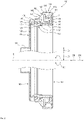
- FIG. 1 an example of a sealing device according to one embodiment and a wheel bearing to which the sealing device may be applied is illustrated.
- a sealing device 100 comprises a first insert body 101 and a second insert body 102 which have an annular shape based on a rotation axis A.
- the first insert body 101 comprises a first frame 110 having an annular shape based on the rotation axis A and a first sealing part 120 coupled to the first frame 110 in a circumferential direction D1 of the rotation axis A.
- the second insert body 102 comprises a second frame 130 having an annular shape based on the rotation axis A and a second sealing part 140 coupled to the second frame 130 in the circumferential direction D1 of the rotation axis A.
- the second frame 130 of the second insert body 102 has a diameter that is smaller than that of the first frame 110.
- the second insert body 102 may rotate relative to the first insert body 101 about the rotation axis A. Further, the first insert body 101 and the second insert body 102 are arranged such that centers of the annular shapes thereof are located on the same rotation axis A. According to the example shown in FIG. 1 , the first insert body 101 is arranged to be spaced apart from the second insert body 102 in a radially outward direction D2 and an axially inward direction D4. Accordingly, the first insert body 101 and the second insert body 102 form a gap 160 therebetween.
- first insert body 101 and the second insert body 102 form a gap 160, which extends between the first sealing part 120 and the second sealing part 140 in the form of an annular shape based on the rotation axis A, between the first sealing part 120 and the second sealing part 140.
- the sealing device 100 blocks foreign materials such as rainwater, sewage, and the like, which are introduced into the gap 160, due to complementary shapes formed in each of the first sealing part 120 and the second sealing part 140.
- the sealing device 100 of one embodiment may be used in a wheel bearing for a vehicle.
- the wheel bearing may comprise two members arranged on the same rotation axis and having a generally cylindrical shape, and a plurality of rolling elements arranged between the two members in the circumferential direction.
- One of the two cylindrical members may be rotated relative to the other member about the rotation axis.
- the two cylindrical members may be rotated relative to each other about the rotation axis.
- the wheel bearing may comprise a cylindrical outer ring 210, a wheel hub 220 which is at least partially located in the outer ring 210, and a plurality of rolling elements 230 arranged between an inner circumferential surface of the outer ring 210 and an outer circumferential surface of the wheel hub 220 in the circumferential direction D1 and configured to rotate or roll.
- the outer ring 210 may be fixed to a portion of a chassis of the vehicle.
- the wheel hub 220 may be coupled to a driving axle or a driven axle of the chassis to be rotated relative to the outer ring 210 about the rotation axis A. Further, the wheel hub 220 may be coupled with a drive wheel or a driven wheel of the vehicle in an axially outward direction D5.
- the rolling elements 230 are metal balls, but the rolling elements 230 are not limited to the metal ball.
- the wheel bearing has an annular gap 240, in which the rolling elements 230 are arranged, between the inner circumferential surface of the outer ring 210 and an outer circumferential surface 221 of the wheel hub 220.
- the sealing device 100 may be mounted at an outboard side of the wheel bearing to seal the gap 240.
- an inner circumferential surface of the first insert body 101 e.g., an inner circumferential surface of the first frame 110
- An inner circumferential surface of the second insert body 102 (e.g., an inner circumferential surface of the second frame 130) is interference fitted on the outer circumferential surface 221 of the wheel hub 220 so that the second insert body 102 is coupled to the outer circumferential surface 221 of the wheel hub 220. Accordingly, the second insert body 102 may be rotated relative to the first insert body 101 about the rotation axis A together with the wheel hub 220. Alternatively, the first insert body 101 may be coupled to the inner circumferential surface of the outer ring 210 by interference fit using the outer circumferential surface of the first frame 110.
- the sealing device 100 according to one embodiment will be described in detail with reference to FIGS. 2 to 4 .
- the first frame 110 has an annular shape, and a center of the annular shape is located on the rotation axis A.
- the second frame 130 has an annular shape, and a center of the annular shape is located on the rotation axis A. As shown in FIGS. 2 and 3 , the first frame 110 has an approximately U-shaped longitudinal cross-sectional shape (a cross-sectional shape taken along the rotation axis A), and the second frame 130 has an approximately N-shaped longitudinal cross-sectional shape.
- the first frame 110 and the second frame 130 may be made of a metal material or a plastic material.
- the first frame 110 comprise a pair of cylindrical portions 111 and 112 and a disc portion 113 extending between the cylindrical portions 111 and 112.
- the cylindrical portions 111 and 112 have an annular shape based on the rotation axis A.
- the disc portion 113 is bent relative to each of the cylindrical portions 111 and 112.
- the cylindrical portion 112 is fitted on the outer circumferential surface 211 of the outer ring 210 ( see FIG. 1 ) by an inner circumferential surface facing a radially inward direction D3 and extending in the circumferential direction D1.
- the second frame 130 comprises a pair of cylindrical portions 131 and 132 and a disc portion 133 extending between the cylindrical portions 131 and 132.
- the cylindrical portions 131 and 132 have an annular shape based on the rotation axis A.
- the cylindrical portion 131 is bent from the disc portion 133 in the axially inward direction D4, and the cylindrical portion 132 is bent from the disc portion 133 in the axially outward direction D5.
- the cylindrical portion 131 which is located in the radially outward direction D2 among a pair of cylindrical portions 131 and 132, is located between a pair of cylindrical portions 111 and 112 of the first frame 110.
- the cylindrical portion 132 is fitted on the outer circumferential surface 221 of the wheel hub 220 ( see FIG. 1 ) by the inner circumferential surface facing the radially inward direction D3 and extending in the circumferential direction D1.
- the first sealing part 120 is integrally coupled to the first frame 110 along the first frame 110 in the circumferential direction D1.
- the second sealing part 140 is integrally coupled to the second frame 130 along the second frame 130 in the circumferential direction D1.
- the first sealing part 120 comprises a base portion 121 which is coupled to the first frame 110 and has an approximately L-shaped longitudinal cross section.
- the first sealing part 120 is coupled to the first frame 110 along a portion of the disc portion 113 and an entirety of the cylindrical portion 112 on the base portion 121.
- the second sealing part 140 comprises a base portion 141 which is coupled to the second frame 130 and has an approximately triangular-shaped longitudinal cross section.
- the second sealing part 140 is coupled to the second frame 130 along an entirety of the cylindrical portion 131 on the base portion 141.
- the first sealing part 120 and the second sealing part 140 may be made of a rubber material or a plastic material.
- the first sealing part 120 and the first frame 110, and the second sealing part 140 and the second frame 130 may be respectively coupled by adhesion.
- a material forming the first sealing part 120 may be molded together with the first frame 110 such that the first insert body 101 is manufactured
- a material forming the second sealing part 140 may be molded together with the second frame 130 such that the second insert body 102 is manufactured.
- the first insert body 101 and the second insert body 102 are arranged such that the gap 160 is formed between the first sealing part 120 and the second sealing part 140. That is, owing to the gap 160, the first sealing part 120 and the second sealing part 140 are positioned in a non-contact state.
- the sealing device 100 reduces a torque required for relative rotations of two relative-rotating components of the wheel bearing (e.g., the outer ring 210 and the wheel hub 220 shown in FIG. 1 ).
- the sealing device 100 of the embodiments gradationally blocks foreign materials infiltrating into the gap 240 ( see FIG. 1 ) between the outer ring and the wheel hub and minimizes infiltration amount of foreign materials such that the gap 240 is sealed with high reliability.
- the gap 160 between the first insert body 101 and the second insert body 102 has a labyrinth shape for preventing infiltration of foreign materials.
- the sealing device 100 of one embodiment comprises one or more annular cavities in the labyrinth-shaped gap 160 to gradationally block foreign materials by the cavities.
- the first sealing part 120 and the second sealing part 140 are formed to define the labyrinth-shaped gap 160 and the cavities between the first insert body 101 and the second insert body 102.
- the sealing device 100 of the embodiments comprises at least one groove 150 for reducing infiltration rates of foreign materials.
- Any one or both of the first sealing part 120 and the second sealing part 140 may comprise the groove 150.
- the groove 150 may be formed on surfaces of the first sealing part 120 and the second sealing part 140, which are in the radially outward direction D2 and face the cavity.
- first sealing part 120 and the second sealing part 140 are formed to define a first cavity 161 having an annular shape based on the rotation axis A and a second cavity 163 spaced apart from the first cavity 161 and having an annular shape based on the rotation axis A in the gap 160 between the first sealing part 120 and the second sealing part 140. Further, the first sealing part 120 and the second sealing part 140 are formed to define a first cavity passage 162 connected to the first cavity 161 and the second cavity 163 and having an annular shape based on the rotation axis A in the gap 160.
- the first sealing part 120 comprises a first lip 122 protruding toward the second sealing part 140 in the axially outward direction D5 and having an annular shape based on the rotation axis A.
- the first lip 122 may be curved or bent so as to partially define the first cavity 161.
- the second sealing part 140 comprises a first baffle 142 which partially defines the first cavity 161 together with the first lip 122.
- the first lip 122 is spaced apart from an inner circumferential surface of the cylindrical portion 111 and the second sealing part 140.
- the first baffle 142 protrudes along an edge of the base portion 141 in the radially outward direction D2 toward the inward direction D4 and has an annular shape based on the rotation axis A.
- the first lip 122 comprises a second baffle 123 extending along a free end thereof and having an annular shape based on the rotation axis A.
- the second baffle 123 may protrude from the free end of the first lip 122 to be inclined or perpendicular with respect to the rotation axis A. Further, the second baffle 123 may be curved with respect to the rotation axis A.
- the second baffle 123 vertically protrudes with respect to the rotation axis A in the radially outward direction D2.
- the second baffle 123 is located to be spaced apart from the first baffle 142 in the radially inward direction D3.
- the free end of the second baffle 123 may be spaced apart from the first baffle 142 in the axially inward direction D4 or in the axially outward direction D5.
- the first baffle 142, the first lip 122, and the second baffle 123 partially define the first cavity 161. Further, the first baffle 142 and the second baffle 123 partially define the first cavity passage 162.
- the first cavity 161 is defined by the inner circumferential surface of the cylindrical portion 111, a surface of the first sealing part 120 in the axially outward direction D5, a surface 122OR of the first lip 122 in the radially outward direction D2, the first baffle 142, and a surface of the second baffle 123 in the axially inward direction D4.
- the first lip 122 comprises at least one or a plurality of grooves 150 on the radially outer surface 122OR facing the first cavity 161.
- the first lip 122 does not comprise a groove 150 on a surface (i.e., a radially inner surface 122IR) opposite to the radially outer surface 122OR on which the grooves 150 are arranged.
- the first lip 122 comprises a flat surface having no irregular shape on the radially inner surface 122IR.
- the second sealing part 140 comprises a second lip 143 protruding toward the first sealing part 120 and having an annular shape based on the rotation axis A.
- the second lip 143 partially defines the second cavity 163.
- the second lip 143 comprises at least one or a plurality of grooves 150 on a radially outer surface 143OR facing the second cavity 163.
- the second cavity 163 is separated from the first cavity 161 by the first lip 122 and is located in the radially inward direction D3 with respect to the first cavity 161.
- the second lip 143 is spaced apart from the first lip 122 in the radially inward direction D3.
- the second lip 143 may be curved or bent to partially define the second cavity 163.
- the second lip 143 comprises a third baffle 144 extending along a free end thereof and having an annular shape based on the rotation axis A.
- the third baffle 144 may protrude from the free end of the second lip 143 to be inclined or perpendicular with respect to the rotation axis A. Further, the third baffle 144 may be curved with respect to the rotation axis A. In the example shown in FIGS. 2 and 3 , the third baffle 144 vertically protrudes with respect to the rotation axis A in the radially outward direction D2.
- the first sealing part 120 and the second sealing part 140 are formed to define a third cavity 165, which communicates with the second cavity 163 and has an annular shape based on the rotation axis A, in the gap 160. Further, the first sealing part 120 and the second sealing part 140 are formed to define a second cavity passage 164, which is connected to the second cavity 163 and the third cavity 165 and has an annular shape based on the rotation axis A, in the gap 160.
- the first sealing part 120 comprises a fourth baffle 125 and a fifth baffle 126 which are spaced apart from each other along the rotation axis A, and the second sealing part 140 comprises a sixth baffle 145 located between the fourth baffle 125 and the fifth baffle 126.
- the fourth baffle 125, the fifth baffle 126 and the sixth baffle 145 have an annular shape based on the rotation axis A and partially define the third cavity 165.
- the second cavity passage 164 is defined in the gap 160 by the second lip 143 and the first sealing part 120.
- the first sealing part 120 comprises an extension portion 124 protruding from the cylindrical portion 112 in the axially outward direction D5 and having an annular shape based on the rotation axis A.
- the fourth baffle 125 and fifth baffle 126 protrude from the extension portion 124 in the radially outward direction D2.
- the sixth baffle 145 is located between the fourth baffle 125 and the fifth baffle 126.
- the sixth baffle 145 protrudes toward the first sealing part 120 in the radially inward direction D3.
- the extension portion 124 of the first sealing part 120 comprises grooves 150 on a radially outer surface 124OR that is between the fourth baffle 125 and the fifth baffle 126.
- the fourth baffle 125 comprises grooves 150 on an axially inner surface 125IA
- the fifth baffle 126 comprises grooves 150 on an axially inner surface 126IA.
- the axially inner surface 125IA of the fourth baffle 125 is perpendicular to the rotation axis A
- an axially outer surface 125OA of the fourth baffle 125 is inclined with respect to the rotation axis A.
- An axially inner surface 145IA of the sixth baffle 145 is perpendicular to the rotation axis A.
- the first cavity passage 162 and the second cavity passage 164 have an annular shape based on the rotation axis A.
- the first cavity passage 162 and the second cavity passage 164 are curved with respect to the rotation axis A to have an approximately L-shaped longitudinal cross section.
- the first cavity passage 162 is located in the radially outward direction D2 than the second cavity passage 164. Further, the first cavity passage 162 is located between both ends of the second cavity passage 164.
- the first cavity passage 162 is defined by a surface of the first baffle 142 in the axially inward direction D4, a surface of the second baffle 123 in the axially outward direction D5, and a surface of the base portion 141 of the second sealing part 140 in the axially inward direction D4.
- the first cavity 161 communicates with the second cavity 163 by the first cavity passage 162.
- the second cavity passage 164 is defined by a portion of the surface 122IR of the first lip 122 in the radially inward direction D3, a surface of the second lip 143 in the radially inward direction D3, a surface of the third baffle 144 in the axially inward direction D4, and a surface of the base portion 121 of the first sealing part 120.
- the second cavity 163 communicates with the third cavity 165 by the second cavity passage 164.
- the sealing device 100 comprises a fourth cavity 166, which is connected to the third cavity 165 and has an annular shape based on the rotation axis A, between the first sealing part 120 and the second frame 130.
- the first sealing part 120 may be formed to define the fourth cavity 166 between the first sealing part 120 and the second frame 130.
- the fourth cavity 166 is spaced apart from the third cavity 165 in the axially outward direction D5.
- the first sealing part 120 comprises a grease lip 127 protruding toward the second frame 130 to be inclined with respect to the rotation axis A and having an annular shape based on the rotation axis A.
- grease lip 127 may prevent leakage of grease which fills in the gap 240 ( see FIG. 1 ) between the outer ring 210 and the wheel hub 220 and lubricates the rolling elements 230 ( see FIG. 1 ).
- the grease lip 127 may come into contact with an outer circumferential surface of the second frame 130 of the second insert body 102 at its free end.
- the fourth cavity 166 is defined by a portion of a surface of the cylindrical portion 131 in the radially inward direction D3, a portion of a surface of the disc portion 133 in the axially inward direction D4, the grease lip 127 and the fifth baffle 126. That is, the grease lip 127 partially defines the fourth cavity 166.
- the base portion 141 comprises a plurality of grooves 150 on a radially outer surface 1410R, which is not surrounded by the first frame 110.
- FIG. 4 illustrates the groove 150 formed on the radially outer surface 122OR of the first lip 122 and the radially inner surface 122IR.
- the groove 150 extends in the circumferential direction D1 of the rotation axis A to form an annular shape.
- Adjacent grooves 150 are spaced apart along the rotation axis A by a flat surface 122FS.
- the flat surface 122FS has an annular shape based on the rotation axis A and extends between adjacent grooves 150.
- the adjacent grooves 150 may be spaced apart by a curved surface.
- a width W of the groove 150 may exceed 0.1 mm.
- An upper limit of the width W of the groove 150 may be determined such that the adjacent grooves 150 may be spaced apart from each other by the flat surface 122FS or the curved surface within the length of the lip of the first sealing part 120 (e.g., the first lip 122) or the lip of the second sealing part 140 (e.g., the second lip 143) along the rotation axis A.
- the width W of the groove 150 exceeds 0.1 mm, the groove 150 may appropriately hold foreign materials therein.
- a cross-sectional shape of the groove 150 may have a semicircular shape.
- the cross-sectional shape of the groove 150 is not limited to the semicircular shape and may have a polygonal shape such as a triangular shape, a quadrangular shape and the like.
- the infiltrating foreign materials may come into contact with the surface of the groove 150.
- the groove 150 may reduce infiltration rates of foreign materials and hold some amount of foreign materials therein.
- the foreign materials having the reduced infiltration rates may move to a lower portion of the wheel bearing along the groove 150 due to gravity.
- the foreign materials moved to the lower portion of the wheel bearing may fall to the radially inner surface 122IR of the first lip 122. Since the radially inner surface 122IR of the first lip 122 does not have a groove 150, the foreign materials may be discharged to the outside of the sealing device 100 in the radially outward direction D2 and the axially outward direction D5 along the radially inner surface 122IR of the first lip 122.
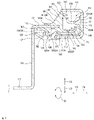
- FIG. 5 is a schematic diagram illustrating a labyrinth-shaped gap defined by the first sealing part and the second sealing part of the sealing device according to one embodiment. An example of a sealing operation of the sealing device 100 will be described with reference to FIGS. 2 to 5 .
- the first cavity 161, the first cavity passage 162, the second cavity 163, the second cavity passage 164 and the third cavity 165 form the labyrinth-shaped gap 160.
- Foreign materials introduced between the first frame 110 and the second sealing part 140 are blocked by the first cavity 161. Since the groove 150 of the first lip 122 located in the first cavity 161 reduces infiltration rates of foreign materials, the foreign materials may be congested in the first cavity 161 and held in the first cavity 161 and also in the groove 150 of the first lip 122. Foreign materials which are not held in the first cavity 161 may infiltrate into the second cavity 163 through the first cavity passage 162.
- first cavity passage 162 of the L-shaped longitudinal cross section is oriented opposite to an inflow direction of foreign materials to form a portion of the labyrinth shape, it is difficult for foreign materials to enter the second cavity 163 from the first cavity 161.
- the groove 150 of the second lip 143 located in the second cavity 163 reduces infiltration rates of foreign materials.
- the foreign materials may be congested and held in the second cavity 163.
- Foreign materials which are not blocked by the second cavity 163 may infiltrate into the third cavity 165 through the second cavity passage 164.
- the second cavity passage 164 of the L-shaped longitudinal cross section is located with an orientation opposite to the orientation of the first cavity passage 162 to form a portion of the labyrinth shape, it is difficult for foreign materials to enter the third cavity 165 from the second cavity 163. Foreign materials which are not blocked by the second cavity 163 may infiltrate into the third cavity 165 through the second cavity passage 164. However, a flow of foreign materials may completely blocked by the fourth baffle 125 and the sixth baffle 145 which vertically protrude with respect to the rotation axis A, and the foreign materials may be held in the third cavity 165.
- the sealing device 100 prevents infiltration of foreign materials with high reliability.
- the groove 150 located in each cavity reduces infiltration rates of foreign materials such that the foreign materials may be easily held in each cavity.
- the second baffle 123 and the third baffle 144 which vertically protrude with respect to the rotation axis A may effectively prevent foreign materials from overflowing into a subsequent cavity.
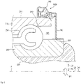
- FIG. 6 illustrates a sealing device according to one embodiment coupled to another example of a wheel bearing.
- a sealing device 100A shown in FIG. 6 is mounted at an inboard side of the wheel bearing.
- the wheel bearing shown in FIG. 6 comprises an inner ring 250 fitted in the outer circumferential surface of the wheel hub 220 facing the inboard side.
- the inner ring 250 has a length that is shorter than that of the wheel hub 220.
- the inner ring 250 is rotated relative to the outer ring 210 together with the wheel hub 220. According to the example shown in FIG.
- the first frame 110 of the first insert body of the sealing device 100A is interference fitted on the outer circumferential surface 211 of the outer ring 210 by an inner circumferential surface thereof so that the first insert body is coupled to the inner circumferential surface 211 of the outer ring 210.
- the second frame 130 of the second insert body is interference fitted on an outer circumferential surface 251 of the inner ring 250 so that the second insert body is coupled to the outer circumferential surface 221 of the inner ring 250.
- the first frame 110 may be coupled to an inner circumferential surface 212 of the outer ring 210 through interference fitting.
- the above-described sealing device 100 of one embodiment comprises the first to third cavities 161, 163, and 165, and the adjacent cavities other among first to third cavities 161, 163, and 165 communicate each other.
- the sealing device of another embodiment may comprise an additional cavity in addition to the above-described cavities.
- each of the first sealing part 120 and the second sealing part 140 may comprise an additional lip and an additional baffle.
- the first lip 122 of the first sealing part 120 may comprise the above-described groove 150 on the surface 122IR thereof in the radially inward direction.
- the groove 150 may extend in a straight-line shape along the rotation axis A or in an oblique diagonal line shape with respect to the rotation axis A, and adjacent grooves 150 may be spaced apart from each other in the circumferential direction D1.
Landscapes
- Engineering & Computer Science (AREA)
- General Engineering & Computer Science (AREA)
- Mechanical Engineering (AREA)
- Physics & Mathematics (AREA)
- Fluid Mechanics (AREA)
- Sealing Using Fluids, Sealing Without Contact, And Removal Of Oil (AREA)
- Sealing With Elastic Sealing Lips (AREA)
- Rolling Contact Bearings (AREA)
Claims (9)
- Dichtungsvorrichtung (100) für ein Radlager, umfassend:einen ersten Einsatzkörper (101), der einen ringförmigen ersten Rahmen (110) und ein erstes Dichtungsteil (120), das mit dem ersten Rahmen (110) gekoppelt ist, umfasst; undeinen zweiten Einsatzkörper (102), der einen ringförmigen zweiten Rahmen (130) umfasst, der einen Durchmesser aufweist, der kleiner ist als der des ersten Rahmens (110), und ein zweites Dichtungsteil (140), das mit dem zweiten Rahmen (130) gekoppelt, wobei:der zweite Einsatzkörper (102) ausgelegt ist, um im Verhältnis zu dem ersten Einsatzkörper (101) um eine Drehachse gedreht zu werden,der erste Einsatzkörper (101) und der zweite Einsatzkörper (102) so angeordnet sind, dass ein Spalt (160) zwischen dem ersten Dichtungsteil (120) und dem zweiten Dichtungsteil (140) gebildet ist,dadurch gekennzeichnet, dassdas erste Dichtungsteil (120) und das zweite Dichtungsteil (140) gebildet sind, um einen ersten Hohlraum (161) zu definieren, der basierend auf der Drehachse eine Ringform aufweist, einen ersten Hohlraumdurchgang (162), der mit dem ersten Hohlraum (161) verbunden ist und basierend auf der Drehachse eine Ringform aufweist, und einen zweiten Hohlraum (163), der mit dem ersten Hohlraumdurchgang (162) verbunden ist und basierend auf der Drehachse in dem Spalt (160) eine Ringform aufweist,das erste Dichtungsteil (120) eine erste Lippe (122) umfasst, die zu dem zweiten Dichtungsteil (140) hin vorsteht und basierend auf der Drehachse eine Ringform aufweist und ausgelegt ist, um teilweise den ersten Hohlraum (161) zu definieren,das zweite Dichtungsteil (140) eine zweite Lippe (143) umfasst, die zu dem ersten Dichtungsteil (120) hin vorsteht und basierend auf der Drehachse eine Ringform aufweist und ausgelegt ist, um teilweise den zweiten Hohlraum (163) zu definieren,die erste Lippe (122) mindestens eine Rille (150) an einer radialen Außenoberfläche davon umfasst, die zu der ersten Hohlraum (161) zeigt,die zweite Lippe (143) mindestens eine Rille (150) an einer radialen Außenoberfläche davon umfasst, die zu dem zweiten Hohlraum (163) zeigt,das zweite Dichtungsteil (120) eine erste Leitwand (142) umfasst, die basierend auf der Drehachse eine Ringform aufweist,die erste Lippe (122) eine zweite Leitwand (123) umfasst, die von der ersten Leitwand (142) in die radiale Richtung nach innen beabstandet ist und basierend auf der Drehachse eine Ringform aufweist; unddie erste Leitwand (142) und die zweite Leitwand (123) teilweise den ersten Hohlraumdurchgang (162) definieren,eine Breite (W) der Rille (150) 0,1 mm überschreitet.
- Dichtungsvorrichtung (100) für ein Radlager nach Anspruch 1, wobei die erste Lippe (122) und die zweite Lippe (143) an einer radialen Innenoberfläche davon eine plane Oberfläche umfassen.
- Dichtungsvorrichtung (100) für ein Radlager nach Anspruch 1, wobei die erste Lippe (122) und die zweite Lippe (143) eine Vielzahl von Rillen (150) umfassen, und angrenzende Rillen (150) unter der Vielzahl von Rillen (150) entlang der Drehachse voneinander beabstandet sind.
- Dichtungsvorrichtung (100) für ein Radlager nach Anspruch 1, wobei die erste Lippe (122) und die zweite Lippe (143) an einer radialen Innenoberfläche davon eine plane Oberfläche umfassen.
- Dichtungsvorrichtung (100) für ein Radlager nach Anspruch 1, wobei die zweite Lippe (143) eine dritte Leitwand (144) umfasst, die basierend auf der Drehachse eine Ringform aufweist.
- Dichtungsvorrichtung (100) für ein Radlager nach Anspruch 1, wobei:das erste Dichtungsteil (120) und das zweite Dichtungsteil (140) gebildet sind, um einen zweiten Hohlraumdurchgang (164) zu definieren, der mit dem zweiten Hohlraum (163) verbunden ist und eine Ringform über die Drehachse aufweist, und einen dritten Hohlraum (165), der mit dem zweiten Hohlraumdurchgang (164) verbunden ist und eine Ringform über die Drehachse in dem Spalt (160) aufweist,das erste Dichtungsteil (120) eine vierte Leitwand (125) und eine fünfte Leitwand (126) umfasst, die entlang der Drehachse voneinander beabstandet sind und basierend auf der Drehachse eine Ringform aufweisen, unddas zweite Dichtungsteil (140) eine sechste Leitwand (145) umfasst, die zwischen der vierten Leitwand (125) und der fünften Leitwand (126) gelegen ist und basierend auf der Drehachse eine Ringform aufweist; unddie vierte Leitwand (125), die fünfte Leitwand (126) und die sechste Leitwand (145) teilweise den dritten Hohlraum (165) definieren.
- Dichtungsvorrichtung (100) für ein Radlager nach Anspruch 6, wobei der erste Hohlraumdurchgang (162) zwischen beiden Enden des zweiten Hohlraumdurchgangs (164) in der radialen Richtung weiter nach außen gelegen ist als der zweite Hohlraumdurchgang (164).
- Dichtungsvorrichtung (100) für ein Radlager nach Anspruch 6, wobei:das erste Dichtungsteil (120) eine Fettlippe (127) umfasst, die mit einer äußeren Umfangsoberfläche des zweiten Rahmens (130) in Berührung kommt und basierend auf der Drehachse eine Ringform aufweist, unddie Fettlippe (127) teilweise einen vierten Hohlraum (166) definiert, der mit dem dritten Hohlraum (165) verbunden ist und basierend auf der Drehachse eine Ringform aufweist.
- Dichtungsvorrichtung (100) für ein Radlager nach Anspruch 1, wobei:das zweite Dichtungsteil (140) einen Basisabschnitt (141) umfasst, der mit dem zweiten Rahmen (130) gekoppelt ist, undder Basisabschnitt (141) mindestens eine Rille (150) an einer radialen Außenoberfläche davon umfasst.
Applications Claiming Priority (2)
| Application Number | Priority Date | Filing Date | Title |
|---|---|---|---|
| KR1020170083455A KR101948759B1 (ko) | 2017-06-30 | 2017-06-30 | 휠 베어링 밀봉 장치 |
| PCT/KR2017/012948 WO2019004525A1 (ko) | 2017-06-30 | 2017-11-15 | 휠 베어링 밀봉 장치 |
Publications (3)
| Publication Number | Publication Date |
|---|---|
| EP3647074A1 EP3647074A1 (de) | 2020-05-06 |
| EP3647074A4 EP3647074A4 (de) | 2021-03-31 |
| EP3647074B1 true EP3647074B1 (de) | 2022-06-29 |
Family
ID=64742381
Family Applications (1)
| Application Number | Title | Priority Date | Filing Date |
|---|---|---|---|
| EP17915779.7A Active EP3647074B1 (de) | 2017-06-30 | 2017-11-15 | Radlagerdichtungsvorrichtung |
Country Status (3)
| Country | Link |
|---|---|
| EP (1) | EP3647074B1 (de) |
| KR (1) | KR101948759B1 (de) |
| WO (1) | WO2019004525A1 (de) |
Families Citing this family (1)
| Publication number | Priority date | Publication date | Assignee | Title |
|---|---|---|---|---|
| KR102536970B1 (ko) * | 2019-02-15 | 2023-05-26 | 주식회사 일진글로벌 | 씰링 기능이 향상된 차량용 휠베어링 |
Family Cites Families (8)
| Publication number | Priority date | Publication date | Assignee | Title |
|---|---|---|---|---|
| JP2525536Y2 (ja) * | 1990-02-16 | 1997-02-12 | エヌオーケー株式会社 | 密封装置 |
| JP4586559B2 (ja) * | 2005-02-14 | 2010-11-24 | 日本精工株式会社 | ハブユニット軸受 |
| WO2010061688A1 (ja) * | 2008-11-28 | 2010-06-03 | Nok株式会社 | 密封装置 |
| ITTO20101005A1 (it) * | 2010-12-16 | 2012-06-17 | Skf Ab | Gruppo cuscinetto-mozzo per la ruota di un veicolo a motore |
| CN104169803B (zh) * | 2012-04-20 | 2018-09-04 | 富士电机株式会社 | 电子照相用感光体、其制造方法和电子照相装置 |
| KR101366145B1 (ko) * | 2012-10-16 | 2014-02-24 | 주식회사 일진글로벌 | 씨일 어셈블리 장착구조와 이를 이용한 차량용 휠 베어링 |
| DE102013220074B4 (de) * | 2013-10-02 | 2015-05-13 | Schaeffler Technologies AG & Co. KG | Schleuderscheibe als Vordichtung für ein Radlager |
| ITUB20160770A1 (it) * | 2015-02-17 | 2017-08-16 | Skf Ab | Complesso di tenuta per cuscinetti di rotolamento, in particolare per unità mozzo ruota di veicoli ed unità mozzo ruota associata. |
-
2017
- 2017-06-30 KR KR1020170083455A patent/KR101948759B1/ko active Active
- 2017-11-15 EP EP17915779.7A patent/EP3647074B1/de active Active
- 2017-11-15 WO PCT/KR2017/012948 patent/WO2019004525A1/ko not_active Ceased
Also Published As
| Publication number | Publication date |
|---|---|
| WO2019004525A1 (ko) | 2019-01-03 |
| EP3647074A1 (de) | 2020-05-06 |
| KR20190003026A (ko) | 2019-01-09 |
| EP3647074A4 (de) | 2021-03-31 |
| KR101948759B1 (ko) | 2019-02-18 |
Similar Documents
| Publication | Publication Date | Title |
|---|---|---|
| EP3650244B1 (de) | Radlagerdichtungsvorrichtung | |
| US10746229B2 (en) | Wheel bearing sealing device and manufacturing method therefor | |
| EP2128501B1 (de) | Hermetische dichtungsvorrichtung | |
| US4770548A (en) | Hydrodynamic seal | |
| JP5901632B2 (ja) | 転がり軸受用のシールアセンブリ | |
| US8308370B2 (en) | Sealing device for bearing | |
| JP6771739B2 (ja) | 密封構造 | |
| JP6384036B2 (ja) | 車輪用軸受装置 | |
| CN113939663B (zh) | 密封装置 | |
| KR102536970B1 (ko) | 씰링 기능이 향상된 차량용 휠베어링 | |
| US20030031393A1 (en) | Bearing with tapered rolling bodies provided with a sealing device | |
| FR2688836A1 (fr) | Roulement de butee de suspension pour vehicule et son procede de montage. | |
| EP3647074B1 (de) | Radlagerdichtungsvorrichtung | |
| JP6777466B2 (ja) | プーリユニット | |
| JP4654779B2 (ja) | シール部材及びシール部材付き転がり軸受ユニット | |
| CN112437853A (zh) | 密封装置 | |
| JP7437723B2 (ja) | 密封装置 | |
| JP4973285B2 (ja) | 車輪支持用軸受ユニット | |
| JP4465755B2 (ja) | 密封板付転がり軸受 | |
| EP2551542B1 (de) | Radnabenlager-/Gleichlaufgelenkeinheit mit Schutzblende | |
| CN115552136B (zh) | 密封装置 | |
| US5957590A (en) | Provisional retaining and sealing device for ball bearings | |
| KR20060017305A (ko) | 차량용 액슬 어셈블리 | |
| JP2005325924A (ja) | 密封装置 | |
| JP5104516B2 (ja) | 軸受用密封装置の取付構造 |
Legal Events
| Date | Code | Title | Description |
|---|---|---|---|
| STAA | Information on the status of an ep patent application or granted ep patent |
Free format text: STATUS: THE INTERNATIONAL PUBLICATION HAS BEEN MADE |
|
| PUAI | Public reference made under article 153(3) epc to a published international application that has entered the european phase |
Free format text: ORIGINAL CODE: 0009012 |
|
| STAA | Information on the status of an ep patent application or granted ep patent |
Free format text: STATUS: REQUEST FOR EXAMINATION WAS MADE |
|
| 17P | Request for examination filed |
Effective date: 20200130 |
|
| AK | Designated contracting states |
Kind code of ref document: A1 Designated state(s): AL AT BE BG CH CY CZ DE DK EE ES FI FR GB GR HR HU IE IS IT LI LT LU LV MC MK MT NL NO PL PT RO RS SE SI SK SM TR |
|
| AX | Request for extension of the european patent |
Extension state: BA ME |
|
| DAV | Request for validation of the european patent (deleted) | ||
| DAX | Request for extension of the european patent (deleted) | ||
| A4 | Supplementary search report drawn up and despatched |
Effective date: 20210302 |
|
| RIC1 | Information provided on ipc code assigned before grant |
Ipc: F16J 15/3264 20160101ALI20210224BHEP Ipc: F16C 33/78 20060101AFI20210224BHEP Ipc: F16J 15/447 20060101ALI20210224BHEP Ipc: B60B 27/00 20060101ALN20210224BHEP Ipc: F16J 15/3244 20160101ALI20210224BHEP Ipc: F16C 33/80 20060101ALI20210224BHEP Ipc: F16J 15/16 20060101ALI20210224BHEP |
|
| REG | Reference to a national code |
Ref country code: DE Ref legal event code: R079 Ref document number: 602017059128 Country of ref document: DE Free format text: PREVIOUS MAIN CLASS: B60B0027000000 Ipc: F16C0033780000 |
|
| GRAP | Despatch of communication of intention to grant a patent |
Free format text: ORIGINAL CODE: EPIDOSNIGR1 |
|
| RIC1 | Information provided on ipc code assigned before grant |
Ipc: B60B 27/00 20060101ALN20211209BHEP Ipc: F16J 15/447 20060101ALI20211209BHEP Ipc: F16J 15/3264 20160101ALI20211209BHEP Ipc: F16J 15/3244 20160101ALI20211209BHEP Ipc: F16J 15/16 20060101ALI20211209BHEP Ipc: F16C 33/80 20060101ALI20211209BHEP Ipc: F16C 33/78 20060101AFI20211209BHEP |
|
| STAA | Information on the status of an ep patent application or granted ep patent |
Free format text: STATUS: GRANT OF PATENT IS INTENDED |
|
| INTG | Intention to grant announced |
Effective date: 20220113 |
|
| GRAS | Grant fee paid |
Free format text: ORIGINAL CODE: EPIDOSNIGR3 |
|
| GRAA | (expected) grant |
Free format text: ORIGINAL CODE: 0009210 |
|
| STAA | Information on the status of an ep patent application or granted ep patent |
Free format text: STATUS: THE PATENT HAS BEEN GRANTED |
|
| AK | Designated contracting states |
Kind code of ref document: B1 Designated state(s): AL AT BE BG CH CY CZ DE DK EE ES FI FR GB GR HR HU IE IS IT LI LT LU LV MC MK MT NL NO PL PT RO RS SE SI SK SM TR |
|
| REG | Reference to a national code |
Ref country code: CH Ref legal event code: EP |
|
| REG | Reference to a national code |
Ref country code: AT Ref legal event code: REF Ref document number: 1501531 Country of ref document: AT Kind code of ref document: T Effective date: 20220715 |
|
| REG | Reference to a national code |
Ref country code: IE Ref legal event code: FG4D |
|
| REG | Reference to a national code |
Ref country code: DE Ref legal event code: R096 Ref document number: 602017059128 Country of ref document: DE |
|
| REG | Reference to a national code |
Ref country code: LT Ref legal event code: MG9D |
|
| PG25 | Lapsed in a contracting state [announced via postgrant information from national office to epo] |
Ref country code: SE Free format text: LAPSE BECAUSE OF FAILURE TO SUBMIT A TRANSLATION OF THE DESCRIPTION OR TO PAY THE FEE WITHIN THE PRESCRIBED TIME-LIMIT Effective date: 20220629 Ref country code: NO Free format text: LAPSE BECAUSE OF FAILURE TO SUBMIT A TRANSLATION OF THE DESCRIPTION OR TO PAY THE FEE WITHIN THE PRESCRIBED TIME-LIMIT Effective date: 20220929 Ref country code: LT Free format text: LAPSE BECAUSE OF FAILURE TO SUBMIT A TRANSLATION OF THE DESCRIPTION OR TO PAY THE FEE WITHIN THE PRESCRIBED TIME-LIMIT Effective date: 20220629 Ref country code: HR Free format text: LAPSE BECAUSE OF FAILURE TO SUBMIT A TRANSLATION OF THE DESCRIPTION OR TO PAY THE FEE WITHIN THE PRESCRIBED TIME-LIMIT Effective date: 20220629 Ref country code: GR Free format text: LAPSE BECAUSE OF FAILURE TO SUBMIT A TRANSLATION OF THE DESCRIPTION OR TO PAY THE FEE WITHIN THE PRESCRIBED TIME-LIMIT Effective date: 20220930 Ref country code: FI Free format text: LAPSE BECAUSE OF FAILURE TO SUBMIT A TRANSLATION OF THE DESCRIPTION OR TO PAY THE FEE WITHIN THE PRESCRIBED TIME-LIMIT Effective date: 20220629 Ref country code: BG Free format text: LAPSE BECAUSE OF FAILURE TO SUBMIT A TRANSLATION OF THE DESCRIPTION OR TO PAY THE FEE WITHIN THE PRESCRIBED TIME-LIMIT Effective date: 20220929 |
|
| REG | Reference to a national code |
Ref country code: NL Ref legal event code: MP Effective date: 20220629 |
|
| REG | Reference to a national code |
Ref country code: AT Ref legal event code: MK05 Ref document number: 1501531 Country of ref document: AT Kind code of ref document: T Effective date: 20220629 |
|
| PG25 | Lapsed in a contracting state [announced via postgrant information from national office to epo] |
Ref country code: RS Free format text: LAPSE BECAUSE OF FAILURE TO SUBMIT A TRANSLATION OF THE DESCRIPTION OR TO PAY THE FEE WITHIN THE PRESCRIBED TIME-LIMIT Effective date: 20220629 Ref country code: LV Free format text: LAPSE BECAUSE OF FAILURE TO SUBMIT A TRANSLATION OF THE DESCRIPTION OR TO PAY THE FEE WITHIN THE PRESCRIBED TIME-LIMIT Effective date: 20220629 |
|
| PG25 | Lapsed in a contracting state [announced via postgrant information from national office to epo] |
Ref country code: NL Free format text: LAPSE BECAUSE OF FAILURE TO SUBMIT A TRANSLATION OF THE DESCRIPTION OR TO PAY THE FEE WITHIN THE PRESCRIBED TIME-LIMIT Effective date: 20220629 |
|
| PG25 | Lapsed in a contracting state [announced via postgrant information from national office to epo] |
Ref country code: SM Free format text: LAPSE BECAUSE OF FAILURE TO SUBMIT A TRANSLATION OF THE DESCRIPTION OR TO PAY THE FEE WITHIN THE PRESCRIBED TIME-LIMIT Effective date: 20220629 Ref country code: SK Free format text: LAPSE BECAUSE OF FAILURE TO SUBMIT A TRANSLATION OF THE DESCRIPTION OR TO PAY THE FEE WITHIN THE PRESCRIBED TIME-LIMIT Effective date: 20220629 Ref country code: RO Free format text: LAPSE BECAUSE OF FAILURE TO SUBMIT A TRANSLATION OF THE DESCRIPTION OR TO PAY THE FEE WITHIN THE PRESCRIBED TIME-LIMIT Effective date: 20220629 Ref country code: PT Free format text: LAPSE BECAUSE OF FAILURE TO SUBMIT A TRANSLATION OF THE DESCRIPTION OR TO PAY THE FEE WITHIN THE PRESCRIBED TIME-LIMIT Effective date: 20221031 Ref country code: ES Free format text: LAPSE BECAUSE OF FAILURE TO SUBMIT A TRANSLATION OF THE DESCRIPTION OR TO PAY THE FEE WITHIN THE PRESCRIBED TIME-LIMIT Effective date: 20220629 Ref country code: EE Free format text: LAPSE BECAUSE OF FAILURE TO SUBMIT A TRANSLATION OF THE DESCRIPTION OR TO PAY THE FEE WITHIN THE PRESCRIBED TIME-LIMIT Effective date: 20220629 Ref country code: AT Free format text: LAPSE BECAUSE OF FAILURE TO SUBMIT A TRANSLATION OF THE DESCRIPTION OR TO PAY THE FEE WITHIN THE PRESCRIBED TIME-LIMIT Effective date: 20220629 |
|
| PGFP | Annual fee paid to national office [announced via postgrant information from national office to epo] |
Ref country code: IT Payment date: 20221128 Year of fee payment: 6 |
|
| PG25 | Lapsed in a contracting state [announced via postgrant information from national office to epo] |
Ref country code: PL Free format text: LAPSE BECAUSE OF FAILURE TO SUBMIT A TRANSLATION OF THE DESCRIPTION OR TO PAY THE FEE WITHIN THE PRESCRIBED TIME-LIMIT Effective date: 20220629 Ref country code: IS Free format text: LAPSE BECAUSE OF FAILURE TO SUBMIT A TRANSLATION OF THE DESCRIPTION OR TO PAY THE FEE WITHIN THE PRESCRIBED TIME-LIMIT Effective date: 20221029 |
|
| REG | Reference to a national code |
Ref country code: DE Ref legal event code: R097 Ref document number: 602017059128 Country of ref document: DE |
|
| PG25 | Lapsed in a contracting state [announced via postgrant information from national office to epo] |
Ref country code: AL Free format text: LAPSE BECAUSE OF FAILURE TO SUBMIT A TRANSLATION OF THE DESCRIPTION OR TO PAY THE FEE WITHIN THE PRESCRIBED TIME-LIMIT Effective date: 20220629 |
|
| PG25 | Lapsed in a contracting state [announced via postgrant information from national office to epo] |
Ref country code: DK Free format text: LAPSE BECAUSE OF FAILURE TO SUBMIT A TRANSLATION OF THE DESCRIPTION OR TO PAY THE FEE WITHIN THE PRESCRIBED TIME-LIMIT Effective date: 20220629 Ref country code: CZ Free format text: LAPSE BECAUSE OF FAILURE TO SUBMIT A TRANSLATION OF THE DESCRIPTION OR TO PAY THE FEE WITHIN THE PRESCRIBED TIME-LIMIT Effective date: 20220629 |
|
| PLBE | No opposition filed within time limit |
Free format text: ORIGINAL CODE: 0009261 |
|
| STAA | Information on the status of an ep patent application or granted ep patent |
Free format text: STATUS: NO OPPOSITION FILED WITHIN TIME LIMIT |
|
| 26N | No opposition filed |
Effective date: 20230330 |
|
| PG25 | Lapsed in a contracting state [announced via postgrant information from national office to epo] |
Ref country code: MC Free format text: LAPSE BECAUSE OF FAILURE TO SUBMIT A TRANSLATION OF THE DESCRIPTION OR TO PAY THE FEE WITHIN THE PRESCRIBED TIME-LIMIT Effective date: 20220629 |
|
| REG | Reference to a national code |
Ref country code: CH Ref legal event code: PL |
|
| GBPC | Gb: european patent ceased through non-payment of renewal fee |
Effective date: 20221115 |
|
| REG | Reference to a national code |
Ref country code: BE Ref legal event code: MM Effective date: 20221130 |
|
| PG25 | Lapsed in a contracting state [announced via postgrant information from national office to epo] |
Ref country code: LI Free format text: LAPSE BECAUSE OF NON-PAYMENT OF DUE FEES Effective date: 20221130 Ref country code: CH Free format text: LAPSE BECAUSE OF NON-PAYMENT OF DUE FEES Effective date: 20221130 |
|
| PG25 | Lapsed in a contracting state [announced via postgrant information from national office to epo] |
Ref country code: SI Free format text: LAPSE BECAUSE OF FAILURE TO SUBMIT A TRANSLATION OF THE DESCRIPTION OR TO PAY THE FEE WITHIN THE PRESCRIBED TIME-LIMIT Effective date: 20220629 Ref country code: LU Free format text: LAPSE BECAUSE OF NON-PAYMENT OF DUE FEES Effective date: 20221115 |
|
| PG25 | Lapsed in a contracting state [announced via postgrant information from national office to epo] |
Ref country code: IE Free format text: LAPSE BECAUSE OF NON-PAYMENT OF DUE FEES Effective date: 20221115 Ref country code: GB Free format text: LAPSE BECAUSE OF NON-PAYMENT OF DUE FEES Effective date: 20221115 |
|
| PG25 | Lapsed in a contracting state [announced via postgrant information from national office to epo] |
Ref country code: BE Free format text: LAPSE BECAUSE OF NON-PAYMENT OF DUE FEES Effective date: 20221130 |
|
| PG25 | Lapsed in a contracting state [announced via postgrant information from national office to epo] |
Ref country code: HU Free format text: LAPSE BECAUSE OF FAILURE TO SUBMIT A TRANSLATION OF THE DESCRIPTION OR TO PAY THE FEE WITHIN THE PRESCRIBED TIME-LIMIT; INVALID AB INITIO Effective date: 20171115 |
|
| PG25 | Lapsed in a contracting state [announced via postgrant information from national office to epo] |
Ref country code: CY Free format text: LAPSE BECAUSE OF FAILURE TO SUBMIT A TRANSLATION OF THE DESCRIPTION OR TO PAY THE FEE WITHIN THE PRESCRIBED TIME-LIMIT Effective date: 20220629 |
|
| PG25 | Lapsed in a contracting state [announced via postgrant information from national office to epo] |
Ref country code: MK Free format text: LAPSE BECAUSE OF FAILURE TO SUBMIT A TRANSLATION OF THE DESCRIPTION OR TO PAY THE FEE WITHIN THE PRESCRIBED TIME-LIMIT Effective date: 20220629 |
|
| PG25 | Lapsed in a contracting state [announced via postgrant information from national office to epo] |
Ref country code: TR Free format text: LAPSE BECAUSE OF FAILURE TO SUBMIT A TRANSLATION OF THE DESCRIPTION OR TO PAY THE FEE WITHIN THE PRESCRIBED TIME-LIMIT Effective date: 20220629 |
|
| PG25 | Lapsed in a contracting state [announced via postgrant information from national office to epo] |
Ref country code: MT Free format text: LAPSE BECAUSE OF FAILURE TO SUBMIT A TRANSLATION OF THE DESCRIPTION OR TO PAY THE FEE WITHIN THE PRESCRIBED TIME-LIMIT Effective date: 20220629 |
|
| PG25 | Lapsed in a contracting state [announced via postgrant information from national office to epo] |
Ref country code: BG Free format text: LAPSE BECAUSE OF FAILURE TO SUBMIT A TRANSLATION OF THE DESCRIPTION OR TO PAY THE FEE WITHIN THE PRESCRIBED TIME-LIMIT Effective date: 20220629 |
|
| PG25 | Lapsed in a contracting state [announced via postgrant information from national office to epo] |
Ref country code: BG Free format text: LAPSE BECAUSE OF FAILURE TO SUBMIT A TRANSLATION OF THE DESCRIPTION OR TO PAY THE FEE WITHIN THE PRESCRIBED TIME-LIMIT Effective date: 20220629 |
|
| PG25 | Lapsed in a contracting state [announced via postgrant information from national office to epo] |
Ref country code: IT Free format text: LAPSE BECAUSE OF NON-PAYMENT OF DUE FEES Effective date: 20231115 |
|
| PG25 | Lapsed in a contracting state [announced via postgrant information from national office to epo] |
Ref country code: IT Free format text: LAPSE BECAUSE OF NON-PAYMENT OF DUE FEES Effective date: 20231115 |
|
| PGFP | Annual fee paid to national office [announced via postgrant information from national office to epo] |
Ref country code: DE Payment date: 20251126 Year of fee payment: 9 |
|
| PGFP | Annual fee paid to national office [announced via postgrant information from national office to epo] |
Ref country code: FR Payment date: 20251124 Year of fee payment: 9 |