EP3647176A1 - Système de changement de vitesses avant de bicyclette - Google Patents
Système de changement de vitesses avant de bicyclette Download PDFInfo
- Publication number
- EP3647176A1 EP3647176A1 EP19206095.2A EP19206095A EP3647176A1 EP 3647176 A1 EP3647176 A1 EP 3647176A1 EP 19206095 A EP19206095 A EP 19206095A EP 3647176 A1 EP3647176 A1 EP 3647176A1
- Authority
- EP
- European Patent Office
- Prior art keywords
- downshift
- chain
- chain ring
- upshift
- big
- Prior art date
- Legal status (The legal status is an assumption and is not a legal conclusion. Google has not performed a legal analysis and makes no representation as to the accuracy of the status listed.)
- Pending
Links
Images























Classifications
-
- B—PERFORMING OPERATIONS; TRANSPORTING
- B62—LAND VEHICLES FOR TRAVELLING OTHERWISE THAN ON RAILS
- B62M—RIDER PROPULSION OF WHEELED VEHICLES OR SLEDGES; POWERED PROPULSION OF SLEDGES OR SINGLE-TRACK CYCLES; TRANSMISSIONS SPECIALLY ADAPTED FOR SUCH VEHICLES
- B62M9/00—Transmissions characterised by use of an endless chain, belt, or the like
- B62M9/04—Transmissions characterised by use of an endless chain, belt, or the like of changeable ratio
- B62M9/06—Transmissions characterised by use of an endless chain, belt, or the like of changeable ratio using a single chain, belt, or the like
- B62M9/10—Transmissions characterised by use of an endless chain, belt, or the like of changeable ratio using a single chain, belt, or the like involving different-sized wheels, e.g. rear sprocket chain wheels selectively engaged by the chain, belt, or the like
- B62M9/12—Transmissions characterised by use of an endless chain, belt, or the like of changeable ratio using a single chain, belt, or the like involving different-sized wheels, e.g. rear sprocket chain wheels selectively engaged by the chain, belt, or the like the chain, belt, or the like being laterally shiftable, e.g. using a rear derailleur
- B62M9/131—Front derailleurs
- B62M9/134—Mechanisms for shifting laterally
- B62M9/1344—Mechanisms for shifting laterally limiting or positioning the movement
- B62M9/1346—Mechanisms for shifting laterally limiting or positioning the movement using cams or plates
-
- B—PERFORMING OPERATIONS; TRANSPORTING
- B62—LAND VEHICLES FOR TRAVELLING OTHERWISE THAN ON RAILS
- B62M—RIDER PROPULSION OF WHEELED VEHICLES OR SLEDGES; POWERED PROPULSION OF SLEDGES OR SINGLE-TRACK CYCLES; TRANSMISSIONS SPECIALLY ADAPTED FOR SUCH VEHICLES
- B62M9/00—Transmissions characterised by use of an endless chain, belt, or the like
- B62M9/04—Transmissions characterised by use of an endless chain, belt, or the like of changeable ratio
-
- B—PERFORMING OPERATIONS; TRANSPORTING
- B62—LAND VEHICLES FOR TRAVELLING OTHERWISE THAN ON RAILS
- B62M—RIDER PROPULSION OF WHEELED VEHICLES OR SLEDGES; POWERED PROPULSION OF SLEDGES OR SINGLE-TRACK CYCLES; TRANSMISSIONS SPECIALLY ADAPTED FOR SUCH VEHICLES
- B62M9/00—Transmissions characterised by use of an endless chain, belt, or the like
- B62M9/04—Transmissions characterised by use of an endless chain, belt, or the like of changeable ratio
- B62M9/06—Transmissions characterised by use of an endless chain, belt, or the like of changeable ratio using a single chain, belt, or the like
- B62M9/10—Transmissions characterised by use of an endless chain, belt, or the like of changeable ratio using a single chain, belt, or the like involving different-sized wheels, e.g. rear sprocket chain wheels selectively engaged by the chain, belt, or the like
- B62M9/105—Transmissions characterised by use of an endless chain, belt, or the like of changeable ratio using a single chain, belt, or the like involving different-sized wheels, e.g. rear sprocket chain wheels selectively engaged by the chain, belt, or the like involving front sprocket chain-wheels engaged by the chain, belt or the like
-
- B—PERFORMING OPERATIONS; TRANSPORTING
- B62—LAND VEHICLES FOR TRAVELLING OTHERWISE THAN ON RAILS
- B62M—RIDER PROPULSION OF WHEELED VEHICLES OR SLEDGES; POWERED PROPULSION OF SLEDGES OR SINGLE-TRACK CYCLES; TRANSMISSIONS SPECIALLY ADAPTED FOR SUCH VEHICLES
- B62M9/00—Transmissions characterised by use of an endless chain, belt, or the like
- B62M9/04—Transmissions characterised by use of an endless chain, belt, or the like of changeable ratio
- B62M9/06—Transmissions characterised by use of an endless chain, belt, or the like of changeable ratio using a single chain, belt, or the like
- B62M9/10—Transmissions characterised by use of an endless chain, belt, or the like of changeable ratio using a single chain, belt, or the like involving different-sized wheels, e.g. rear sprocket chain wheels selectively engaged by the chain, belt, or the like
- B62M9/12—Transmissions characterised by use of an endless chain, belt, or the like of changeable ratio using a single chain, belt, or the like involving different-sized wheels, e.g. rear sprocket chain wheels selectively engaged by the chain, belt, or the like the chain, belt, or the like being laterally shiftable, e.g. using a rear derailleur
- B62M9/131—Front derailleurs
- B62M9/132—Front derailleurs electrically or fluid actuated; Controls thereof
-
- B—PERFORMING OPERATIONS; TRANSPORTING
- B62—LAND VEHICLES FOR TRAVELLING OTHERWISE THAN ON RAILS
- B62M—RIDER PROPULSION OF WHEELED VEHICLES OR SLEDGES; POWERED PROPULSION OF SLEDGES OR SINGLE-TRACK CYCLES; TRANSMISSIONS SPECIALLY ADAPTED FOR SUCH VEHICLES
- B62M9/00—Transmissions characterised by use of an endless chain, belt, or the like
- B62M9/04—Transmissions characterised by use of an endless chain, belt, or the like of changeable ratio
- B62M9/06—Transmissions characterised by use of an endless chain, belt, or the like of changeable ratio using a single chain, belt, or the like
- B62M9/10—Transmissions characterised by use of an endless chain, belt, or the like of changeable ratio using a single chain, belt, or the like involving different-sized wheels, e.g. rear sprocket chain wheels selectively engaged by the chain, belt, or the like
- B62M9/12—Transmissions characterised by use of an endless chain, belt, or the like of changeable ratio using a single chain, belt, or the like involving different-sized wheels, e.g. rear sprocket chain wheels selectively engaged by the chain, belt, or the like the chain, belt, or the like being laterally shiftable, e.g. using a rear derailleur
- B62M9/131—Front derailleurs
- B62M9/134—Mechanisms for shifting laterally
-
- B—PERFORMING OPERATIONS; TRANSPORTING
- B62—LAND VEHICLES FOR TRAVELLING OTHERWISE THAN ON RAILS
- B62M—RIDER PROPULSION OF WHEELED VEHICLES OR SLEDGES; POWERED PROPULSION OF SLEDGES OR SINGLE-TRACK CYCLES; TRANSMISSIONS SPECIALLY ADAPTED FOR SUCH VEHICLES
- B62M9/00—Transmissions characterised by use of an endless chain, belt, or the like
- B62M9/04—Transmissions characterised by use of an endless chain, belt, or the like of changeable ratio
- B62M9/06—Transmissions characterised by use of an endless chain, belt, or the like of changeable ratio using a single chain, belt, or the like
- B62M9/10—Transmissions characterised by use of an endless chain, belt, or the like of changeable ratio using a single chain, belt, or the like involving different-sized wheels, e.g. rear sprocket chain wheels selectively engaged by the chain, belt, or the like
- B62M9/12—Transmissions characterised by use of an endless chain, belt, or the like of changeable ratio using a single chain, belt, or the like involving different-sized wheels, e.g. rear sprocket chain wheels selectively engaged by the chain, belt, or the like the chain, belt, or the like being laterally shiftable, e.g. using a rear derailleur
- B62M9/131—Front derailleurs
- B62M9/136—Chain guides; Mounting thereof
-
- B—PERFORMING OPERATIONS; TRANSPORTING
- B62—LAND VEHICLES FOR TRAVELLING OTHERWISE THAN ON RAILS
- B62M—RIDER PROPULSION OF WHEELED VEHICLES OR SLEDGES; POWERED PROPULSION OF SLEDGES OR SINGLE-TRACK CYCLES; TRANSMISSIONS SPECIALLY ADAPTED FOR SUCH VEHICLES
- B62M9/00—Transmissions characterised by use of an endless chain, belt, or the like
- B62M9/04—Transmissions characterised by use of an endless chain, belt, or the like of changeable ratio
- B62M9/06—Transmissions characterised by use of an endless chain, belt, or the like of changeable ratio using a single chain, belt, or the like
- B62M9/10—Transmissions characterised by use of an endless chain, belt, or the like of changeable ratio using a single chain, belt, or the like involving different-sized wheels, e.g. rear sprocket chain wheels selectively engaged by the chain, belt, or the like
- B62M9/12—Transmissions characterised by use of an endless chain, belt, or the like of changeable ratio using a single chain, belt, or the like involving different-sized wheels, e.g. rear sprocket chain wheels selectively engaged by the chain, belt, or the like the chain, belt, or the like being laterally shiftable, e.g. using a rear derailleur
- B62M9/131—Front derailleurs
-
- B—PERFORMING OPERATIONS; TRANSPORTING
- B62—LAND VEHICLES FOR TRAVELLING OTHERWISE THAN ON RAILS
- B62M—RIDER PROPULSION OF WHEELED VEHICLES OR SLEDGES; POWERED PROPULSION OF SLEDGES OR SINGLE-TRACK CYCLES; TRANSMISSIONS SPECIALLY ADAPTED FOR SUCH VEHICLES
- B62M9/00—Transmissions characterised by use of an endless chain, belt, or the like
- B62M9/04—Transmissions characterised by use of an endless chain, belt, or the like of changeable ratio
- B62M9/06—Transmissions characterised by use of an endless chain, belt, or the like of changeable ratio using a single chain, belt, or the like
- B62M9/10—Transmissions characterised by use of an endless chain, belt, or the like of changeable ratio using a single chain, belt, or the like involving different-sized wheels, e.g. rear sprocket chain wheels selectively engaged by the chain, belt, or the like
- B62M9/12—Transmissions characterised by use of an endless chain, belt, or the like of changeable ratio using a single chain, belt, or the like involving different-sized wheels, e.g. rear sprocket chain wheels selectively engaged by the chain, belt, or the like the chain, belt, or the like being laterally shiftable, e.g. using a rear derailleur
- B62M9/131—Front derailleurs
- B62M9/133—Front derailleurs changing gears automatically
-
- B—PERFORMING OPERATIONS; TRANSPORTING
- B62—LAND VEHICLES FOR TRAVELLING OTHERWISE THAN ON RAILS
- B62M—RIDER PROPULSION OF WHEELED VEHICLES OR SLEDGES; POWERED PROPULSION OF SLEDGES OR SINGLE-TRACK CYCLES; TRANSMISSIONS SPECIALLY ADAPTED FOR SUCH VEHICLES
- B62M9/00—Transmissions characterised by use of an endless chain, belt, or the like
- B62M9/04—Transmissions characterised by use of an endless chain, belt, or the like of changeable ratio
- B62M9/06—Transmissions characterised by use of an endless chain, belt, or the like of changeable ratio using a single chain, belt, or the like
- B62M9/10—Transmissions characterised by use of an endless chain, belt, or the like of changeable ratio using a single chain, belt, or the like involving different-sized wheels, e.g. rear sprocket chain wheels selectively engaged by the chain, belt, or the like
- B62M9/12—Transmissions characterised by use of an endless chain, belt, or the like of changeable ratio using a single chain, belt, or the like involving different-sized wheels, e.g. rear sprocket chain wheels selectively engaged by the chain, belt, or the like the chain, belt, or the like being laterally shiftable, e.g. using a rear derailleur
- B62M9/131—Front derailleurs
- B62M9/134—Mechanisms for shifting laterally
- B62M9/1342—Mechanisms for shifting laterally characterised by the linkage mechanisms
Definitions
- the present disclosure is generally directed to front shifting systems for bicycles, and more particularly to a front shifting system that is incorporated as a part of a crank assembly of a bicycle.
- a bicycle typically includes a system for driving a chain on a bicycle to provide motive force for the system.
- a driving system typically involves a front and a rear drive.
- Rear cassette and front chain ring shifting systems for bicycles are known in the art. Such shifting systems typically utilize a front or rear derailleur to move the chain from one sprocket or chain ring to another.
- the typical front or rear derailleur is mounted to a stationary part of a frame of a bicycle.
- a rear derailleur is typically mounted to or directly adjacent to the rear wheel dropouts on the bicycle frame.
- the frame is often provided with a bracket at the dropout location for attaching the rear derailleur.
- crank assembly may include two crank arms connected by a spindle.
- the crank assembly may also include one or more driving sprockets. When two or more driving sprockets are used various techniques for shifting the chain from one driving sprocket to another driving sprocket have been used.
- a front gear changing device such as a front derailleur typically mounted to a frame of a bicycle
- the front derailleur is typically mounted to the seat tube or other part of a bicycle frame that is closely adjacent the front chain rings of the crank assembly. An open, accessible location must then be left on the seat tube frame to accommodate clamping a front derailleur to the tube.
- a mounting bracket is provided on the bicycle frame for attaching the front derailleur to the frame.
- Existing front derailleurs can create several other problems, disadvantages, or drawbacks for the bicycle, including the frame designer.
- the frame designer must account for a mounting location for the front derailleur when designing the frame of a bicycle with a front shifting system.
- a portion of the frame must be left accessible and positioned relatively close to the front chain rings.
- design constraints on the designer It is possible that, when mounting the front derailleur to the bicycle frame, the derailleur is incorrectly positioned relative to the front chain rings. This can reduce the quality and effectiveness of a front shifting operation or can result in the inability to shift, particularly when the chain is under heavy loads.
- mounting the front derailleur to a portion of the bicycle frame effectively makes the frame a part of the front shifting system. While a bicycle is being ridden, the frame can flex when under stress. Any movement or flexing of the frame where the front derailleur is mounted or between that mounting location and the attachment point of the front chain rings can cause shifting problems. For example, a rider may attempt to execute a shift operation while the frame is flexed, resulting in misalignment of the front derailleur and the front chain rings. Such misalignment can again result in poor shift quality, cause the chain to derail, or allow the chain to slip during the shift. Such misalignment may again result in the inability to execute a shift, particularly under heavy chain loads.
- the known front derailleur designs also can make installation and bicycle set-up more difficult, and thus more time consuming and/or expensive.
- the installer must take the steps necessary to separately obtain the clamps or fasteners, the necessary tools, and the derailleur and then install the front derailleur on the bicycle frame.
- the installer, or another person tuning or setting up the bicycle must then also properly position and align the front derailleur relative to the front chain rings during set-up of the system.
- the set-up can be difficult to do for those lacking specific skills and training. Proper positioning and alignment of the front derailleur relative to the front chain rings is required to ensure quality shifting capability.
- the front shifting assembly includes a front shift unit configured to be coupled to a crank assembly for rotation therewith about a rotation axis, the front shift unit having a chain ring component and a shift mechanism coupled to the chain ring component.
- the chain ring component has a big chain ring having a plurality of teeth defining a big chainring plane and a small chain ring having a plurality of teeth defining a small chainring plane, the small chain ring having a small diameter and the big chain ring having a big diameter that is larger than the small diameter.
- the shift mechanism includes at least one protruding shift element disposed in a transition zone between the big chain ring and the small chain ring, the shift mechanism configured to move the at least one protruding shift element axially between the big chainring plane and the small chainring plane.
- the front shift unit also includes a shift mechanism coupled to the chain ring component, the shift mechanism including an electronic control unit, a gearmotor unit, at least one upshift element, at least one downshift element, and a power supply arranged to provide power for the electronic control unit and the gearmotor unit to operate the at least one upshift element and the at least one downshift element.
- the at least one upshift element is disposed in a transition zone between the small chain ring teeth and the big chain ring teeth and axially movable by the electronic control unit and the gearmotor unit to shift a chain from the plurality of small ring sprocket teeth on the small chain ring to the plurality of big ring sprocket teeth on the big chain ring.
- the at least one downshift element is operable by the electronic control unit and the gearmotor unit to shift a chain from the plurality of big ring sprocket teeth on the big chain ring to the plurality of small ring sprocket teeth on the small chain ring.
- the present disclosure is related to front shifting systems for bicycles and to bicycles that incorporate such front shifting systems.
- the disclosed front shifting systems and bicycles solve or improve upon the above-noted and/or other problems and disadvantages with prior known front shifting systems and bicycles.
- the front shifting systems disclosed herein is incorporated entirely on the chain ring components, with no part separately attached to the bicycle frame. This provides frame designers with greater freedom of design, since the designers do not have to accommodate a portion of the front shifting system on the frame.
- the disclosed front shifting systems thus also eliminate the possibility of incorrectly positioning a portion of the front shifting system relative to the chain rings.
- the disclosed front shifting systems also improve shift performance because, since the bicycle frame is not a part of the front shifting system, any flex in the frame during use does not cause any problems while shifting.
- the disclosed front shifting systems can also be installed on bicycle frames that are not designed for mounting a front gear changer or derailleur.
- the disclosed front shifting systems shift smoothly and consistently, even while under heavy chain loads.
- the disclosed front shifting systems are easier to install and set up than a traditional front gear changer or derailleur and do not require specific skills or training.
- Exchanging, or shifting, a chain between two or more sprockets may be accomplished with at least one ("1") shift element being moved into a chainline of a drive system.
- the shift elements may be protruding shift elements may move in an axial direction relative to a rotational axis of the sprockets.
- the protruding shift elements may be configured to extend and/or retract in the axial direction for moving into and/or out of the chainline.
- the at least one moving shift element may be disposed radially between a root circle of a larger sprocket and a tooth tip of a smaller sprocket.
- the at least one moving shift element may include an array or plurality of protruding shift elements.
- the protruding shift elements of the array may be disposed at different radial distances relative to the larger and/or smaller sprockets.
- Exchanging, or shifting, a change between two or more sprockets may be accomplished from a larger sprocket to a smaller sprocket using downshifting element, which may be formed as a slide or slanted planar surface that may be moved into, and/or out of, the chainline at the larger sprocket to cause the chain to slide or shift towards the smaller sprocket.
- downshifting element which may be formed as a slide or slanted planar surface that may be moved into, and/or out of, the chainline at the larger sprocket to cause the chain to slide or shift towards the smaller sprocket.
- a device for a cycle drive train may include movable shift elements.
- the movable shift elements may be disposed on a chain ring structure.
- the device for a cycle drive train may include movable down shift elements.
- the movable down shift elements may include a slanted surface configured to be moved into a chainline of a large chain ring.
- the device for a cycle drive train may include electronic and/or electrical elements configured to control and/or operate shift elements.
- the electronic and/or electrical elements may be disposed on a chain ring structure.
- the electronic and/or electrical elements may include an electric motor, electrical linear actuators, solenoids, or other electrical devices operable to cause motion or movement. In an example, the electric motor, or other electrical motive device, is configured to cause movement of the shift elements.
- FIG. 1 depicts one example of a bicycle 100 with a frame 102, a front wheel 104 coupled to a fork 106 of the frame, and a rear wheel 108 coupled to seat stays 110 and chain stays 112 on the frame.
- the wheels 104, 108 support the frame 102 above a surface on which the bicycle 100 can travel in a forward direction indicated by the arrow 'A'.
- the bicycle 100 has a handlebar assembly 114 that is mounted to a head tube 116 of the frame 102.
- the bicycle 100 also has a seat 118 carried by a seat post 120 received in a seat tube 122 of the frame 102.
- the bicycle 100 has a multiple-geared drivetrain 124 that may have one or both of a front gear changer (described further below as a front shifting system) and a rear gear changer mounted to the frame 102.
- the gear changers may be electromechanical derailleurs, for example, including a rear derailleur 126 and a front shifting system, which is described in detail below.
- the gear changers can be operable using a one or more gear shifters 128, which may be mounted to the handlebar assembly 114.
- the gear shifters 128 may operate the gear changes through wireless communication, as in the disclosed example, or via a physical connection using a mechanical shift cable or hydraulic line (not shown).
- the drivetrain 124 includes chain rings, also described in detail below, that are driven by a crank assembly 132, which has two crank arms 134 and two pedals, respectively 136.
- the chain rings are connected by a chain 138 to a plurality of sprockets on the frame 102 at the rear wheel 108.
- the plurality of sprockets may be identified as a rear cassette 140 mounted to the frame 102 coaxial with the rear wheel 108.
- the bicycle 100 as described above, other than the chain rings and the front shifting system, is known in the art and is shown in FIG. 1 to be a mountain bike.
- Those having ordinary skill in the art should recognize that the type and style of bicycle may vary from the disclosed example.
- a road bicycle with drop-style handlebars, along with a drivetrain having road type gearing with a road gear range may be used instead of a mountain bike or other bicycle gear range.
- the bicycle 100 includes brake system.
- the brake system includes at least one brake lever 142 that is movably connected to the handlebar assembly 114.
- the brake lever 142 is configured to operate components of the braking system of the bicycle 100.
- the brake system can include one or both of a hydraulic or cable actuated front brake mechanism 144 coupled to the front wheel 104 via a hydraulic line or mechanical cable 146 and a hydraulic or cable actuated rear brake mechanism (not shown) coupled to the rear wheel 108 through a hydraulic line or mechanical cable 148.
- the brake system can be a hydraulic actuated system or a mechanical actuated system and both are known in the art.
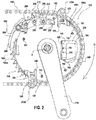
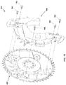
- FIGS. 2 and 3 show substantial portions of a front shifting system of the drivetrain 124 of the bicycle 100 constructed in accordance with the teachings of the present disclosure and from the right side of the bicycle.
- the front shifting system includes a front shift unit 150.
- the crank arms 134 of the crank assembly 132 are carried as part of the front shift unit 150, around which the chain 138 is routed, as shown in FIG. 2 .
- FIG. 3 shows the same view of the front shifting system, but with the chain 138 removed.
- the front shift unit 150 carries all the components of the disclosed front shifting system, other than the gear shifter 128 or wireless actuator.
- the wireless gear shifter 128 of the front shifting system is not carried on the front shift unit 150 since it needs to be in easy reach of a rider of the bicycle 100.
- the gear shifter 128 may instead be mounted remotely on the handlebar assembly 114 of the bicycle 100, as noted above.
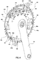
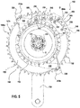
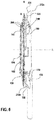
- FIGS. 4-6 show perspective, left side, and edge views of the portions of the front shifting system and front shift unit 150 depicted in FIGS. 2 and 3 .
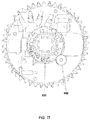
- the front shift unit 150 has two chain rings 152 and 154 that are fixedly connected to and concentric with one another in order to rotate together about a rotation axis R of the front shift unit.
- the chain rings 152, 154 are rotationally or torsionally engaged with one of the crank arms 134 through a mutual splined connection 156.
- the crank arm 134 is retained to the front shift unit 150 by a plurality of screws 158, which have threads configured to engage threaded holes (not shown) in the crank arm around the splined connection 156.
- FIGS. 7-9 depict several views of a small segment of the chain 138.
- the chain 138 can be formed of a plurality of inner and outer links that are joined together.
- the inner links are formed by pairs of inner plates 164 that define a narrower tooth space 166 between the plates.
- the outer links are formed by pairs of outer plates 168 that define a wider tooth space 170 between the plates.
- the plates 164, 168 and links are joined to one another by rivets or pins 172 across the links and the width of the chain 138.
- the rivets 172 can each optionally carry a roller 174 disposed between the plates and may include a bushing (not shown) between the rollers and rivets.
- the small chain ring 154 is positioned inboard or to the left of the big chain ring 152 in this example.
- the sprocket teeth 160 of the big chain ring 152 may be configured to have alternating narrow teeth 160n and wide teeth 160w as can be seen in FIGS. 4 and 6 .
- the sprocket teeth 162 of the small chain ring 154 may be configured to have alternating narrow teeth 162n and wide teeth 162w.
- the teeth 160 and 162 around the respective chain rings 152, 154 may alternate between being narrow teeth 160n or 162n to fit the narrower tooth spaces 166 between the inner plates 164 and wide teeth 160w or 162w to substantially fill the wider tooth spaces 170 between the outer plates 168 of the chain 138.
- a cover or cowling 180 is fixedly attached to the outboard or right facing side of the front shift unit 150 by screws 182 or other suitable fasteners or methods.
- the cowling 180 is sized to cover a substantial portion of the outboard side of the front shift unit 150 and shaped, i.e., smooth and rounded or domed, to reduce aerodynamic resistance to the bicycle's forward motion.
- the cowling 180 may be structural in nature (as opposed to being primarily an aerodynamic cover) to add strength and stiffness to the front shift unit 150.
- the cowling 180 can be configured to keep road debris away from the more sensitive parts of the front shift unit 150 and to prevent the rider from accidentally coming into contact with these sensitive parts.
- the main components of the front shifting system on the front shift unit 150 are first introduced below. More specific details of each of the main components, various additional sub-components, and ancillary components according to the teachings of the present disclosure are then described below. The function and operation of each of the main components, sub-components, and ancillary components are then described. Lastly, the shifting function and operation of the front shifting system are also described below.
- the front shifting system includes components configured and arranged to shift the chain 138 between the big chain ring 152 and the small chain ring 154 according to a rider's selective operation of the shifter 128.
- the disclosed front shifting system can upshift the chain 138 from the small chain ring 154 to the big chain ring 152 and can downshift the chain from the big chain ring to the small chain ring. Upshifts and downshifts are performed smoothly and quickly by the disclosed front shifting system and are performed with components that are disposed entirely on the front shift unit 150.
- the front shifting system includes a control unit 184, which may be a waterproof electronic device.
- the control unit 184 is attached to the front shift unit 150 by screws or other fasteners 186.
- the control unit 184 is attached to the outboard or right side of the big chain ring 152.
- the control unit 184 contains a printed circuit board (PCB).
- the printed circuit board may include a wireless radio and antenna, a microprocessor, and spring-biased electrical contacts.
- the wireless radio and antenna can send and receive shift commands to and from a rider-controlled actuator, such as the aforementioned shifter 128, which may be located on the handlebar assembly 114 of the bicycle 100.
- the wireless radio and antenna may also be used to communicate with the electronic rear derailleur 126.
- the microprocessor can receive, process, and send out electronic signals.
- the microprocessor, wireless radio, and antenna can be contained within a waterproof housing or case 188 of the control unit 184.
- the control unit 184 may also have a button 190 and a light emitting diode (LED) 192 or other illumination element that are exposed on the housing 188.
- the button 190 can be an electronic switch that is actuated by the rider.
- the button 190 may be used for pairing the control unit 184 of the front shift unit 150 with the shifter 128 on the handlebar assembly 114 and, optionally, for pairing the control unit 184 and thus the front shift unit 150 with the electronic rear derailleur 126.
- the LED 192 may be a multi-color LED, such as a red-green-blue (RGB) LED or a red-green-blue-white (RGBW) LED.
- the LED may thus be capable of producing light in three colors and be configured to provide visual feedback to the rider to indicate a state of the front shifting system.
- the printed circuit board may also include an electronic audio or noise emitter that can provide audible feedback to the rider.
- the front shifting system includes a power supply, which may be a rechargeable power supply 194 as described herein, for providing power to operate the front shifting system.
- the power supply 194 is attached to the housing 188 of the control unit 184.
- a latch 196 may be provided and actuated so that the power supply 194 can be quickly and easily installed, removed, and replaced by a rider without the use of a tool.
- the power supply 194 may be a lithium-ion type rechargeable power supply or may be another suitable power supply type, if desired.
- the power supply 194 is attached to the housing 188 of the control unit 184, the power supply is in electrical contact with the spring-biased electrical contacts and can supply electrical energy to the PCB.
- the front shifting system also includes a gearmotor unit 200, which may be a waterproof electromechanical device.
- the gearmotor unit 200 is mounted to the right or outboard side of the big chain ring 152.
- the gearmotor unit 200 may be attached via screws 202 or other suitable fasteners to a bracket 204 carried on the outboard side of the big chain ring 152.
- the bracket 204 may likewise be attached or mounted to the big chain ring 152 by similar fasteners or screws.
- the bracket 204 may be formed as an integral portion of the big chain ring 152 or as an integral portion of a housing of the gearmotor unit 200 to reduce the number of parts to be assembled from three to two.
- the gearmotor unit 200 can include an electric motor (not shown) and a gear train (not shown).
- the gear train can be configured to reduce speed and increase power output, i.e., output torque produced by the electric motor of the gearmotor unit 200.
- the gear train can be internal to the gearmotor unit 200 and can be connected to and drive rotation of a mechanical output portion of the gearmotor unit 200.
- the gearmotor unit 200 can also include an angular position sensing system (not shown) that senses the angular position of the mechanical output portion of gearmotor unit 200.
- the gearmotor unit 200 receives electric power and electronic signals from the control unit 184 and can do so via an electric cable (not shown).
- the front shifting system also includes a chain guard or guard rail 206 that is attached to the big chain ring 152 on the right side or outboard side.
- the chain guard rail 206 may be attached to the big chain ring 152 by screws 208 or other suitable fasteners.
- the chain guard rail 206 is sized and positioned to guide the chain 138, as necessary during use and while shifting, in order to help prevent the chain 138 from derailing to the outboard side of big chain ring 152.
- the chain guard rail 206 is placed adjacent the sprocket teeth 160 and spaced therefrom to the outboard side.
- the chain guard rail 206 acts as an outboard direction barrier for the chain 138.
- the front shifting system further includes an upshift element 210 that is carried on the big chain ring 152.
- the upshift element 210 is on the right side or outboard side of the big chain ring 152 and is pivotable about its lower edge relative to the outboard side.
- the upshift element 210 can be made from aluminum so that the element is lightweight and yet strong and durable.
- the upshift element 210 may be cast aluminum in one example.
- the upshift element 210 is configured to selectively guide the chain 138 from the sprocket teeth 162 of the small chain ring 154 to the sprocket teeth 160 of the big chain ring 152, as described in further detail below.
- the upshift element 210 may be injection molded from a Nylon material or a long fiber reinforced thermoplastic material.
- Various components of the upshift element 210, as described below, may also be attached separately to the upshift element 210 or may instead be molded or otherwise formed as an integral portion of the element.
- the front shifting system also includes at least one downshift element carried on the right side or outboard side of the big chain ring 152.
- the front shifting system includes two such elements including a first downshift element 212a and a second downshift element 212b, each being pivotable about a central portion thereof relative to the outboard side.
- the first and second downshift elements 212a and 212b are disposed generally 180 degrees opposite one another around the circumference of the front shift unit 150.
- each downshift element 212a and 212b can also be made from aluminum so that each element is lightweight and yet strong and durable.
- the first and second downshift elements 212a and 212b may be cast aluminum in one example.
- each downshift element 212a and 212b in an alternate example, may be injection molded from a Nylon material or a long fiber reinforced thermoplastic material.
- first downshift element 212a and second downshift element 212b have the same construction and configuration. Thus, only one downshift element may be shown or described in detail below. However, it should be understood that such illustrations and description may apply equally to either of the first and second downshift elements 212a and 212b.
- the first and second downshift elements 212a and 212b are generally configured to selectively guide the chain 138 from the sprocket teeth 160 of the big chain ring 152 to the sprocket teeth 162 of the small chain ring 154, as described in further detail below.
- the front shifting system may include only one of the downshift elements or may include more than two of the downshift elements, if desired.
- the mechanical output portion of the gearmotor unit 200 is identified herein generally as a motor output 214, which can be in the form of an output shaft or a disc, bracket, horn, or the like coupled to such an output shaft via a splined interface or other suitable connection.
- the motor output 214 in this example may be axially retained to the gearmotor unit 200 by a screw or other suitable fastener (not shown).
- a hub 216 may be attached to the motor output 214, also by screws 218 or other suitable fasteners.
- the hub 216 can be a circular disc or other suitable device for connecting the gearmotor unit 200 to other components of the front shifting system.
- the hub has a circumferential slot 217 formed around the perimeter of the hub.
- a first link 220a and a second link 220b are connected to the hub 216.
- Each link 220a and 220b is a relatively thin, elongate element with a hole at each end.
- the hub 216 also has two holes formed through the hub and may be disposed 180 degrees opposite one another around the circumference of the hub. The proximal ends of the first link 220a and second link 220b are received in the slot 217 with their holes aligned with a corresponding one of the two holes in the hub 216.
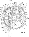
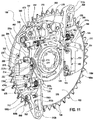
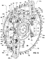
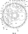
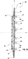
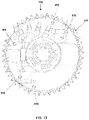
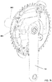
- FIGS. 14-16 show perspective and plan views of what is defined herein as a chain ring component 228, which includes the big chain ring 152 and the small chain ring 154.
- the outboard side of the big chain ring 152 has a surface 226 with numerous optional features provided thereon. These optional features may each be integrally formed by a machining, casting, or other suitable process as an integrated part of the surface 226 of the big chain ring 152. Alternatively, a number of these optional features may be formed as separate components and attached to the surface 226 of the big chain ring 152 by welding, rivets, screws, or other suitable fasteners, or attachment techniques.
- the surface 226 may include a shallow recessed landing 230 that is sized and configured to receive the housing 188 of the control unit 184 therein.
- the landing 230 can assist in providing an easily identifiable mounting location for properly positioning the control unit 184 when installed on the surface 230.
- the surface 226 may include a shallow motor recess 232 that is sized and configured to receive the gearmotor unit 200 therein.
- the brackets 224 as noted above, may be integrally formed as a part of the surface 226 or may be separately attached thereto adjacent the motor recess 232.
- a shallow pocket 234 may be formed having a semi-circular shape to provide clearance depth in the surface 226 for the hub 216.
- the pocket 234 may be formed adjacent the brackets 224 but on the opposite side of the brackets relative to the motor recess 232.
- Recessed first and second channels 236a and 236b may be formed extending in opposite directions from the pocket 234 to accommodate the respective first and second links 220a and 220b (see also FIG. 13 ).
- the surface 226 also include an upshifter recess 238 formed having a semi-circular shape to accommodate upshift driver and actuator components, as described below.
- a shaft support 240 is positioned adjacent to the upshifter recess 238 and includes a bore 242 that extends through the support for receiving a shaft, also as described below.
- the surface 226 further includes a first downshifter recess 244a, also formed having a semi-circular shape, to accommodate a first downshift driver component, as described below.
- a shaft support 246 is positioned adjacent to the first downshifter recess 244a and includes a bore 248 that extends through the support for receiving a shaft, also as described below.
- the upshifter recess 238 and the first downshifter recess 244a are positioned spaced laterally apart on the surface 226.
- the outboard side surface 226 of the big chain ring 152 further includes a second downshifter recess 244b, also formed having a semi-circular shape, to accommodate a second downshift driver component, as described below.
- a pair of spaced apart shaft supports 250 is positioned adjacent to and on opposite sides of the second downshifter recess 244b.
- Each of the shaft supports 250 includes a bore 252 that extends through the support for receiving a shaft, also as described below.
- the shaft supports 250 are positioned across the second downshifter recess 244b from one another such that the bores 252 are concentrically aligned with one another.
- the second downshifter recess 244b is connected to the second channel 236b so that the second link 220b can extend from the hub pocket 234 to the second downshifter recess 244b along the second channel.
- the surface 226 also includes a first downshift element depression 254a that is positioned above and spaced from the first downshifter recess 244a.
- the first downshift element depression 254a is shaped and configured to accommodate the first downshift element 212a, as described below.
- a pair of spaced apart shaft supports 256 is positioned adjacent to and on opposite sides of the first downshift element depression 254a.
- Each of the shaft supports 256 includes a bore 258 that extends through the support for receiving a shaft, also as described below.
- the shaft supports 256 are positioned across the first downshift element depression 254a from one another such that the bores 256 are concentrically aligned with one another.
- the surface 226 further includes a second downshift element depression 254b that is positioned below and spaced from the second downshifter recess 244b.
- the second downshift element depression 254b is shaped and configured to accommodate the second downshift element 212b, as described below.
- a pair of spaced apart shaft supports 260 is positioned adjacent to and on opposite sides of the second downshift element depression 254b.
- Each of the shaft supports 260 includes a bore 262 that extends through the support for receiving a shaft, also as described below.
- the shaft supports 260 are positioned across the second downshift element depression 254b from one another such that the bores 262 are concentrically aligned with one another.
- the hole 264b is smaller and further from the axis R than the hole 264a.
- the hole 264c is smaller and further from the axis R than the hole 264b.
- the hole 264d is smaller and further from the axis R than the hole 264c.
- each of the chain guiding and chain upshifting pegs 280 and 282 may be formed from a hardened steel for wear resistance, durability, and strength. However, these peg and hook elements may be formed of other suitable materials, if desired.
- the upshift element 210 and the chain guiding and chain upshifting pegs 280, 282 may be formed as one integral unit from the same material, if desired.
- each of the chain guiding pegs 280 may instead be formed as a unique element to present the hook at a different, required depth.
- the bores 278a-e can each be blind bores and the barrel ends 286, 300 may each have a different length to automatically set the depth of each chain guiding and chain upshifting peg or element when installed.
- the barrels and bores can also be configured with features that will automatically set the rotational position of each peg when installed. Further, each bore may have a different size to aid in installing the correct peg element in the correct bore on the upshift element 210.
- the first and second downshift elements 212a and 212b have the same configuration and construction in this example.
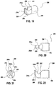
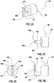
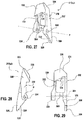
- FIGS. 27-29 show the first downshift element 212a, which is described in some detail. The description is equally applicable to the second downshift element 212b as well and thus each is shown and referenced herein with the same features and reference numbers.
- the first downshift element 212a includes a body 320 with a proximal end, a distal end, and a fulcrum 322 disposed generally between the ends.
- a pair of coaxial holes 324 are disposed spaced apart across a width of the body 320 and define a pivot axis P at the fulcrum 322.
- a head 334 is connected to the distal ends of the legs 332.
- the proximal end of the head 334 connected to the legs 332 is thicker than the legs to define a contoured surface 336 (see FIG. 28 ) that faces radially inward toward the fulcrum axis P.
- the contoured surface 336 has a non-flat contour and is oriented at an angle, i.e., non-parallel relative to the axis P (see FIGS. 27 and 29 ).
- the head 334 also defines a contact face 338 on a tangential surface of the head.
- the contact face 338 is angled, i.e., non-parallel relative to a radial reference between the axis P and the distal end of the downshift element 212a.
- the contact face 338 is configured to engage the chain 138, as is described in more detail below.
- the upshift element 210 of the front shifting system is associated with two upshift driving components that effect movement of the upshift element, as described in greater detail below.
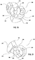
- one of the upshift driving components is an upshift driver 340 depicted in FIG. 30 .
- the upshift driver 340 has a cylinder-shaped hub 342 with a central hole 344 formed axially through the hub.
- the upshift driver 340 rotates about the axis of the central hole 344.
- Two torque protrusions 346 protrude axially from a face 347 of the hub 342.
- the torque protrusions 346 are wedge shaped and are positioned 180 degrees opposite one another around the central hole 344.
- the torque protrusions 346 are configured to transmit torque during use, as described below.
- a drive body 348 of the upshift driver 340 protrudes radially from the hub 342 relative to the axis of the central hole 344.
- a link hole 350 is formed through the drive body 348.
- the link hole 350 has an axis that is parallel to, but spaced radially apart from, the axis of the central hole 344.
- a threaded bore 352 is formed radially into the hub 342 and is oriented perpendicular to axis of the central hole 344.
- a portion of the drive body 348 forms a first spring contact surface 354 that is configured and arranged to engage a torsion spring or return spring, as described below.
- the first spring contact surface 354 faces radially inward toward the axis of the central hole 344 but lies in a plane that is spaced from or tangential relative to the axis.
- the other of the upshift driving components is an upshift actuator 360 depicted in FIG. 31 .
- the upshift actuator 360 also has a cylinder-shaped hub 362 with a central hole 364 formed axially through the hub.
- the upshift actuator 360 rotates about the axis of the central hole 364.
- Two torque protrusions 366 protrude axially from a face 368 of the hub 362.
- the torque protrusions 366 are also wedge shaped and are also positioned 180 degrees opposite one another around the central hole 364.
- the face 368 of the upshift actuator 360 contacts the face 347 of the upshift driver 340 and the torque protrusions 366 are configured to rotationally engage the torque protrusions 344 on the upshift driver 340 to transmit torque during use, as described below.
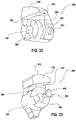
- a protrusion 390 of the first downshift driver 380 protrudes radially from the hub 382 relative to the axis of the central hole 384.
- a threaded bore 392 is formed radially into the hub 382 and is oriented perpendicular to axis of the central hole 384.
- An undercut portion of the protrusion 390 forms a first spring contact surface 394 that is configured and arranged to engage a torsion spring or return spring, as described below.
- the first spring contact surface 394 faces radially inward toward the axis of the central hole 384 but lies in a plane that is spaced from or tangential relative to the axis.
- the other of the downshift driving components is a first downshift cam 400 depicted in FIG. 33 .
- the first downshift cam 400 has a cylinder-shaped hub 402 with a central hole 404 formed axially through the hub.
- the first downshift cam 400 rotates about the axis of the central hole 404.
- Two torque protrusions 406 protrude axially from a face 408 of the hub 402.
- the torque protrusions 406 are also wedge shaped and are also positioned 180 degrees opposite one another around the central hole 404.
- the face 408 of the first downshift cam 400 contacts the face 388 of the first downshift driver 380 and the torque protrusions 406 are configured to rotationally engage the torque protrusions 386 on the first downshift driver 380 to transmit torque during use, as described below.
- the second downshift element 212b of the front shifting system is also associated with two downshift driving components that effect movement of the second downshift element, as described in greater detail below.
- one of the downshift driving components is a second downshift driver 420 depicted in FIG. 34 .
- the second downshift driver 420 also has a cylinder-shaped hub 422 with a central hole 424 formed axially through the hub.
- the second downshift driver 420 also rotates about the axis of the central hole 424.
- Two torque protrusions 426 protrude axially from a face 428 of the hub 422.
- the torque protrusions 426 are also wedge shaped and are positioned 180 degrees opposite one another around the central hole 424.
- the torque protrusions 426 are configured to transmit torque during use, as described below.
- a lobe 430 of the second downshift driver 420 protrudes radially from the hub 422 relative to the axis of the central hole 424.
- a link hole 432 is formed through the lobe 430.
- the link hole 432 has an axis that is parallel to, but spaced radially apart from, the axis of the central hole 424.
- An undercut portion of the lobe 430 forms a first spring contact surface 434 that is configured and arranged to engage a torsion spring or return spring, as described below.
- the first spring contact surface 434 faces radially inward toward the axis of the central hole 424.
- the other of the downshift driving components is a second downshift cam 440 depicted in FIG. 35 .
- the second downshift cam 440 is substantially similar to the first downshift cam 400 and thus also has a cylinder-shaped hub 442 with a central hole 444 formed axially through the hub.
- the second downshift cam 440 rotates about the axis of the central hole 444.
- Two torque protrusions 446 protrude axially from a face 448 of the hub 442.
- the torque protrusions 446 are also wedge shaped and are also positioned 180 degrees opposite one another around the central hole 444.
- the face 448 of the second downshift cam 440 contacts the face 428 of the second downshift driver 420 and the torque protrusions 446 are configured to rotationally engage the torque protrusions 426 on the second downshift driver 420 to transmit torque during use, as described below.
- a cam arm 450 of the first downshift cam 440 protrudes radially from the hub 442 relative to the axis of the central hole 444.
- a cam surface 452 on the cam arm 450 faces in an outward radial direction at the end of the cam arm.
- the cam surface 452 is curved, may be concentric with the axis of the central hole 444, and is configured to contact a portion of the second downshift element 212b to move the element during use, as is described in further detail below.
- An undercut portion of the cam arm 450 forms a second spring contact surface 454 that is configured and arranged to engage a torsion spring or return spring, as described below.
- the second spring contact surface 454 also faces radially inward toward the axis of the central hole 444 but lies in a plane that is spaced from or tangential relative to the axis.
- a first cam shaft 460 extends between the shaft support 240 adjacent the upshifter recess 238 and the shaft support 246 adjacent the first downshifter recess 244a on the big chain ring 152 (see FIGS. 14 and 15 ).
- the first cam shaft 460 extends through the bores 242 and 248 (see FIGS. 14 and 16 ) of the corresponding shaft supports 240 and 246.
- a retainer such as a snap ring or a retaining ring 462 (see FIG. 10 ) can be employed on at least one end or on both ends of the first cam shaft 460 to axially retain the shaft and prevent it from being withdrawn from the bores 242, 248 in the shaft supports 240, 246.
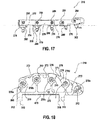
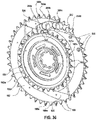
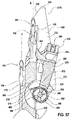
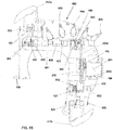
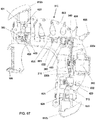
- the upshift element 210 is rotatably supported on the first cam shaft 460 between the shaft supports 240 and 246. More specifically, the first cam shaft is received through the bores 312 in the gudgeons 310 on the bottom edge of the body 270 of the upshift element 210. Referring also to FIGS. 5 , 13-15 , 18 , 36 , and 37 , the series of bores 278a-d in the upshift element 210 align with respective ones of the series of holes 264a-d in the big chain ring 152.
- the teeth 288 on the chain guiding pegs 280 which are seated in the bores 278a-d in the body 270 of the upshift element 210, are positioned to correspondingly align with the series of holes 264a-d in the big chain ring 152.
- the guard rail 206 which is mounted to the big chain ring 152, includes a bore 264e that is positioned radially outboard of the big chain ring 152.
- the hook 302 on the chain upshift peg 282, which is seated in the bore 278e in the body 270 of the upshift element 210, is positioned to correspondingly align with the hole 264e in the guard rail 206.
- the big chain ring 152 includes a gap 464 among the sprocket teeth 160 on the perimeter of the chain ring.
- the hole 264e in the guard rail 206 is positioned to align with the gap 464.
- the hook 302 of the chain upshifting hook 282 also aligned with the gap 464.
- the series of holes 264a-d are arranged in an arc and are spaced apart from one another in a circumferential direction on the big chain ring 152.
- an upshift biasing element such as a torsion spring 466
- the torsion spring 466 is provided on the first cam shaft 460.
- the torsion spring 466 has a first leg 468 seated in a notch 470 in the bottom edge on the body 270 of the upshift element 210 and engages the upshift element.
- the torsion sprig 466 also has a second leg 472 borne against the surface 226 of the big chain ring 152.
- the legs 468 and 472 of the torsion spring 466 bias the upshift element 210 about the axis of the first cam shaft 460 in a direction toward the big chain ring 152, which is counterclockwise in FIG. 13 .
- the gearmotor unit 200 is seated in the motor recess 232 in the surface 226 on the big chain ring 152.
- the hub 216 extending from the gearmotor unit 200 is positioned over the pocket 234.
- One end, the proximal end, of the first link 220a is pivotally connected to the hub 216 by the first pin 222a, which is received through the hole in the proximal end of the link and is retained by one of the retaining rings 224.
- the first link 220a extends along the first recessed channel 236a in the surface 226 of the big chain ring 152.
- the upshift driver 340 is positioned over the upshifter recess 238 and the first cam shaft 460 is received through the central hole 344 in the hub 342 of the upshift driver.
- a first drive pin 474a is received through the link hole 350 in the drive body 348 on the upshift driver 340 and though a hole in the other end, the distal end, of the first link 220a.
- the first drive pin 474a connects the first link 220a to the upshift driver 340 and is retained by another retainer, such as a snap ring or retaining ring 476. In this way, the first link 220a is rotatably connected to the upshift driver 340.
- a set screw 478 is received in the threaded bore 352 on the upshift driver 340.
- the internal end of the set screw 478 can engage a flat surface (not shown) on the first cam shaft 460 to rotationally fix the upshift driver 340 to the first cam shaft so that rotation of the upshift driver rotates the first cam shaft, as described below.
- the upshift actuator 360 is also positioned over the upshifter recess 238.
- the first cam shaft 460 is rotatably received through the central hole 364 in the hub 362 of the upshift actuator 360.
- the actuator arm 370 is positioned facing and within the upshifter recess 238.
- the upshift actuator 360 is positioned adjacent the upshift driver 340 on the first cam shaft 460 with their respective faces 368 and 347 closely confronting one another.
- the torque protrusions 366 of the upshift actuator 360 overlap axially with the torque protrusions 346 on the upshift driver 340. Thus, the torque protrusion 366 and 346 can rotationally engage with one another.
- An upshift biasing element such as a torsion spring, i.e., an upshift spring 480 is disposed on the first cam shaft 460 and axially between the upshift driver 340 and the upshift actuator 360.
- a first leg (not shown) of the upshift spring 480 contacts or engages the first spring contact surface 354 on the upshift driver 340.
- a second leg 482 of the upshift spring 480 contacts or engages the second spring contact surface 374 on the upshift actuator 360.
- the upshift spring 480 is disposed and arranged to rotationally bias the torque protrusions 346 on the upshift driver 340 against the torque protrusions 366 on the upshift actuator 360, as shown in FIG. 38 .
- the first downshift driver 380 is positioned over the first downshifter recess 244a and the first cam shaft 460 is also received through the central hole 384 in the hub 382 of the first downshift driver.
- a set screw 486 is received in the threaded bore 392 on the first downshift driver 380.
- the internal end of the set screw 486 can engage another flat surface (not shown) on the first cam shaft 460 to rotationally fix the first downshift driver 380 to the first cam shaft so that rotation of the first cam shaft also rotates the first down shift driver, as discussed further below.
- the first downshift cam 400 is also positioned over the first downshifter recess 244a.
- the first cam shaft 460 is rotatably received through the central hole 404 in the hub 402 of the first downshift cam.
- the cam arm 410 is positioned facing and within the first downshifter recess 244a.
- the first downshift cam 400 is positioned adjacent the first downshift driver 380 on the first cam shaft 460 with their respective faces 408 and 388 closely confronting one another.
- the torque protrusions 406 of the first downshift cam 400 overlap axially with the torque protrusions 386 on the first downshift driver 380. Thus, the torque protrusion 406 and 386 can rotationally engage with one another.
- a first downshift biasing element such as a torsion spring, i.e., a first downshift spring 490 is disposed on the first cam shaft 460 and axially between the first downshift driver 380 and the first downshift cam 400.
- a first leg (not shown) of the first downshift spring 490 contacts or engages the first spring contact surface 394 on the first downshift driver 380.
- a second leg 492 of the first downshift spring 490 contacts or engages the second spring contact surface 414 on the first downshift cam 400.
- the first downshift spring 490 is disposed and arranged to rotationally bias the torque protrusions 386 on the first downshift driver 380 against the torque protrusions 406 on the first downshift cam 400, as shown in FIG. 39 .
- the first downshift shaft 496a is also received through the holes 324 at the fulcrum 322 to pivotally support the first downshift element 212a on the shaft and relative to the supports 256.
- a first downshifter biasing element i.e., a first downshifter spring 500a, such as a torsion spring, may be disposed on the first downshift shaft 496a.
- a first leg (not shown) of the first downshifter spring 500a can engage the surface 226 of the big chain ring 152.
- a second leg 502 of the first downshifter spring 500a can engage a spring contact surface 504 between the holes 324 of the fulcrum 322 on the first downshift element 212a.
- the first downshift spring 500a is configured and arranged to bias the head 334 and contact face 338 of the first downshift element 212a in a direction away from the big chain ring 152, the direction being counterclockwise in FIG. 39 .
- a second cam shaft 506 extends between the shaft supports 250 adjacent the second downshifter recess 244b on the big chain ring 152 (see FIGS. 14 and 15 ).
- the second cam shaft 506 extends through the bores 252 (see FIGS. 14 and 16 ) of the shaft supports 250.
- a pair of retainers, such as snap rings or retaining rings 508 can be employed on the ends of the first cam shaft 506 to axially retain the shaft and prevent it from being withdrawn from the bores 252 in the shaft supports 250.
- the other end, the distal end, of the second link 220b is received in the slot 436 in the lobe 430 of the second downshift driver 420A.
- a second drive pin 474b is received through the link hole 432 in the lobe 430 and though a hole in the distal end of the second link 220b.
- the second drive pin 474b rotatably connects the second link 220b to the second downshift driver 420 and is retained by another retainer, such as a snap ring or retaining ring (not shown). In this way, the second link 220b is rotatably connected to the second downshift driver 420 and drives rotation of the second downshift driver 420, as described below.
- the second downshift cam 440 is also positioned over the second downshifter recess 244b.
- the second cam shaft 506 is rotatably received through the central hole 444 in the hub 442 of the second downshift cam 440.
- the cam arm 450 is positioned facing and within the second downshifter recess 244b.
- the second downshift cam 440 is positioned adjacent the second downshift driver 420 on the second cam shaft 506 with their respective faces 448 and 428 closely confronting one another.
- the torque protrusions 446 of the second downshift cam 440 overlap axially with the torque protrusions 426 on the second downshift driver 420.
- the torque protrusion 446 and 426 can rotationally engage with one another.
- the second downshift element 212b is positioned over the second downshift element recess 254b in the surface 226 of the big chain ring 152.
- the fulcrum 322 of the second downshift element 212b is received in the second downshift element recess 254b.
- a second downshift shaft 496b is received through the bores 262 of the supports 260 adjacent the second downshift element recess 254b.
- the second downshift shaft 494b is retained axially by a retaining element, such as a snap ring or retaining ring 498b at each end of the shaft.
- the second downshift shaft 496b is also received through the holes 324 at the fulcrum 322 to pivotally support the second downshift element 212b on the shaft and relative to the supports 260.
- a second downshifter biasing element i.e., a second downshifter spring 500b, such as a torsion spring, may be disposed on the second downshift shaft 496b.
- a first leg (not shown) of the second downshifter spring 500b can engage the surface 226 of the big chain ring 152.
- a second leg 502 of the second downshifter spring 500b can engage a spring contact surface 504 between the holes 324 of the fulcrum 322 on the second downshift element 212b.
- the second downshift spring 500b is configured and arranged to bias the head 334 and contact face 338 of the second downshift element 212b in a direction away from the big chain ring 152, the direction being counterclockwise in FIG. 40 .
- the components of the front shifting system and the front shift unit 150 can vary in configuration and construction from the example shown and described herein.
- the specific components and component arrangement can also vary. More specifically, the characteristics, such as the shape, size, depth, height, width, length, and location of the features, including the various shaft supports, recesses, holes, and depressions, on the surface 226 of the big chain ring 152 can also vary. Some of the features and/or components may instead be part of or carried on the small chain ring 154 of the front shift unit 150. Also, the physical details, such as the location, size, shape, structure, and material of the various drivers, actuators, cams, and upshift and downshift elements can vary from the examples described above.
- the type, size, location, and arrangement of the various sub-components, including the cam shafts, pins, links, and biasing elements, can also vary from the examples shown and described herein. Also, details, such as the location, type, arrangement, size, physical input and output characteristics, electrical power consumption, and mechanical power output, of the electro-mechanical and electronic components, including the gearmotor unit and the control unit, can also vary from the examples disclosed and described herein. As will be evident to those having ordinary skill in the art upon reading this disclosure, the front shifting system disclosed and described herein can function as intended though changes are made to the component examples.
- the disclosed front shifting system has two shifting states and has two operational states.
- the operational states in this example include a first operational state, i.e., a big chain ring state, and a second operational state, i.e., a small chain ring state.
- a first operational state i.e., a big chain ring state
- a second operational state i.e., a small chain ring state.
- the big chain ring state as shown in FIG. 2
- the chain 138 is on the big chain ring 152 and remains engaged with the sprocket teeth 160 on the big chain ring with the bicycle 100 in a corresponding gear and a rider pedaling the bicycle.
- the small chain ring state as shown in FIG.
- the front shifting states include a first state, i.e., an upshift state, and a second state, i.e., a downshift state.
- a first state i.e., an upshift state
- a second state i.e., a downshift state.
- the upshift state the front shifting system and the components of the front shift unit 150 are operated, positioned or repositioned, and arranged to shift the chain 138 onto the big chain ring 152 and into engagement with the sprocket teeth 160 on the big chain ring.
- the front shifting system and the components of the front shift unit 150 are operated, positioned or repositioned, and arranged to shift the chain 138 onto the small chain ring 154 and into engagement with the sprocket teeth 162 on the small chain ring.
- the upshift state of the front shift unit 150 is illustrated and the upshifting operation is now described.
- a rider When a rider is riding the bicycle 100 in the small chain ring operational state, as depicted in FIG. 41 , with the chain 138 on and engaged with the small chain ring 154, the rider may shift the bicycle using the shifter 128.
- the rider may press a button on the shifter 128 to execute a gear shift or a shift change that results in the chain 138 shifting from the small chain ring 154 to the big chain ring 152.
- This operation is defined herein as an upshift or an upshifting operation.
- Actuating the shifter 128 results in a wireless signal being sent by a radio transmitter or transceiver of the shifter to the front shift unit 150. More specifically, the wireless signal may be received by a radio receiver or transceiver on the PCB of the control unit 184. The wireless signal may be processed by the microprocessor of the PCB and then a signal and power is transmitted to the gearmotor unit 200.
- the clearance between the actuator surface 372 on the actuator arm 370 and the body 270 of the upshift element 210 is sufficient to allow the upshift element to rotate in the counterclockwise direction toward the surface 226 of the big chain ring 152.
- the biasing force applied by the torsion spring 466 against the body 270 of the upshift element 210 drives rotation of the upshift element about the axis of the first cam shaft 460.
- the holes 264a-264e are clear of the chain 138 when the guard rail 206 and the upshift element 210 are positioned on a rear end or back end of the front shift unit 150 and between upper (forward moving direction) and lower (rearward return direction) segments of the chain.
- the torsion spring 466 biases the upshift element 210 to the position shown in FIGS. 13 and 38 adjacent the surface 226 of the big chain ring 152.
- the second downshift cam 440 does not contact the second downshift element 212b.
- the cam surface 452 on the cam arm 450 of the second downshift cam 440 is clear and spaced from, and thus does not contact the notch 330 on the cam surface 328 of the body 320 of the second downshift element 212b.
- the clearance between the cam surface 452 on the cam arm 450 of the second downshift cam 440 and the cam surface 328 on the body 320 of the second downshift element 212b is again sufficient to allow the second downshift element to rotate in the counterclockwise direction about the fulcrum axis P in FIG. 40 .
- the second downshift element 212b is rotated by the biasing force of the second downshifter spring 500b.
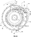
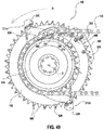
- the chain 138 is released from the small chain ring 154 and upshifts from the small chain ring 154 to the big chain ring 152, as shown sequentially in FIGS. 41 and 47-52 .
- the chain 138 is carried on the small chain ring 154 and the rider is pedaling the drivetrain 124, and the small chain ring, in the direction of the arrow D.
- the chain guiding pegs 280 and chain upshifting peg 282 are approaching from under, but have not yet reached, the chain 138.
- a first or leading chain guiding peg 280 which is protruding through the hole 264a of the big chain ring 152, encounters the chain 138 and begins to engage the chain.
- the sprocket teeth 160 on the big chain ring 152 can include alternating narrow teeth 160n and wide teeth 160w, which can respectively engage the narrow tooth spaces 166 between the inner plates 164 (i.e., narrow links) and the wide tooth spaces 170 between the outer links 168 (i.e., wide links) of the chain.
- the small chain ring 154 can also include such alternating narrow teeth 162n and wide teeth 162w.
- the chain guiding pegs 280 and chain upshifting peg 282 are timed or synced and spaced to engage the wide chain links and the teeth 288 and 302 are sized to engage the wide tooth spaces 170.
- the chain guiding pegs and chain upshifting peg, and the respective teeth can be sized and spaced to engage alternating wide and narrow links and tooth spaces of the chain or to engage only the narrow links and tooth spaces of the chain.
- the biasing force of the upshift spring 480 causes the upshift actuator 360 to also rotate in the clockwise direction in concert with the upshift driver 340. This rotation keeps the torque protrusions 366 of the upshift actuator 360 firmly biased against and in contact with the torque protrusions 346 of the upshift driver 340.
- the actuator surface 372 of the upshift actuator 360 comes into contact and bears against the inboard side or face on the body 270 of the upshift element 210.
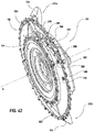
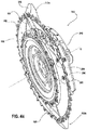
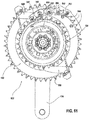
- the first downshift cam 400 When the first downshift element 212a is free to rotate, the first downshift cam 400 will rotate in the counterclockwise direction in FIGS. 39 and 58 under the biasing force of the first downshift spring 490. Rotation of the first downshift cam 400 will drive rotation of the first downshift element 212a in the clockwise direction of FIGS. 39 and 58 about the first downshift shaft 496a. As the first downshift element 212a rotates in the clockwise direction, the angled contact face 338 on the head 334 of the first downshift element moves toward the plane B of the big chain ring 152 until the head overlaps the plane and the sprocket teeth 160, as shown in FIGS. 46 and 58 .
- the curvature of the cam surface 412 may be cylindrically shaped and concentric with the axis of the first cam shaft 460.
- any force vector exerted by the cam surface 328 on the drive arm 326 of the first downshift element 212a against the cam surface 412 of the first downshift cam 400 in the downshift state of FIG. 58 would pass through the axis of the first cam shaft 460.
- the front shifting system is in the downshift state, but a downshift has not yet been described or completed.
- the angled contact face 338 on the head 334 of the first downshift element 212a is biased to overlap the plane B of the big chain ring 152.
- the upshift element 210 including the chain guiding pegs 280 and the chain upshifting peg 282 are biased in a direction away from the plane S of the small chain ring 154.
- the front shifting unit 150 has another, i.e., the second downshift element 212b as noted earlier, not just the one or first downshift element 212a, which is described above in detail.
- the downshift state of the front shift unit 150 is illustrated.
- the wireless signal is again received by the radio or wireless receiver or transceiver on the PCB of the control unit 184.
- the processor or microprocessor of the control unit 184 then processes the signal and an appropriate signal and power is sent to the gearmotor unit 200.
- the first downshift element 212a is actuated or moved to the downshift state
- the second downshift element 212b is also moved or actuated to the downshift state
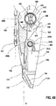
- the second downshift cam 440 When the second downshift element 212b is free to rotate, the second downshift cam 440 will rotate in the counterclockwise direction in FIGS. 40 and 60 under the biasing force of the second downshift spring 512. Rotation of the second downshift cam 440 will drive rotation of the second downshift element 212b in the clockwise direction of FIGS. 40 and 60 about the second downshift shaft 496b. As the second downshift element 212b rotates in the clockwise direction, the angled contact face 338 on the head 334 of the second downshift element moves toward the plane B of the big chain ring 152 until the head overlaps the plane and the sprocket teeth 160, as shown in FIGS. 46 and 60 .
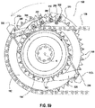
- the chain 138 downshifts from the sprocket teeth 160 of the big chain ring 152 to the small chain ring 154 as shown in FIG. 59 . More specifically, as the second downshift element 212b rises into contact with the chain 138, the angled contact face 338 on the second downshift element blocks the chain from engaging the sprocket teeth 160 on the big chain ring 152. Instead, the angled contact face 338 forces the chain 138 to redirect or deflect out of alignment with the plane B of the big chain ring in the inboard direction toward the plane S of the small chain ring 154.
- the front shift unit 150 in this example includes two downshift elements 212a and 212b.
- the two downshift elements are oriented about 180 degrees opposite one another on the big chain ring 152.
- the downshift elements provide two opportunities to execute or perform a downshift per each revolution of the crank assembly 132.
- a downshift operation can be executed faster than if the front shift unit 150 h ad only one downshift element.
- the front shifting system can be provided in an alternate example with only one downshifting element or can be provided with more than two downshifting elements.
- the front shift unit 150 includes only one upshift element 210, along with the two downshift elements 212a and 212b.
- the front shift unit may include a second or more upshift elements as well.
- the front shifting system may include any number of upshift elements and/or downshift elements within the sprit and scope of the disclosure. Increasing the number of upshift and downshift elements will decrease the average time that it takes to complete a shift by placing a next available shift element that much closer to the upper working side of the chain when a shift is requested or executed.
- the angled bottom surface 294 and the chamfered surfaces or chamfers 296a, 296b, and 296c on the teeth 288 and the angled bottom surface 306 and the chamfered surfaces or chamfers 308a, 308b, 308c on the hook 302 are configured so that the chain 138 does not engage with the chain guiding pegs 280 or the chain upshifting peg 282.
- These angled surfaces and chamfers protect against a chain derailment that could occur if the chain 138 were to engage the chain guiding pegs 280 or the chain upshifting pegs while the rider is pedaling backwards.
- the front shifting system may include an optional power meter 530 that is deployed and configured to measure the rider's power output while pedaling the bicycle 100.
- the power meter 530 is provided as a part of a modified front shift unit 532.
- the power meter 530 may include strain measurement devices attached to the material of the chainring structure between a torque input and output section so as to measure power transmitted therethrough.
- the power meter 530 may include an independent PCB including appropriate circuitry to determine, and/or transmit signals indicative of, power transmitted through the chainring structure. Electrical power to operate the power meter 530 may be supplied by the power supply 194 via a cable (not shown) extending from the power supply to the power meter.
- the power meter 530 and the front shift unit 532 may share PCB within the control unit 184, rather than having a separate PCB for the power meter and the front shift unit.
- strain measurement devices may still be attached to the chainring structure and configured to measure strain of the chainring structure.
- the front shifting system may be configured for what is termed "synchro shifting.”
- synchro shifting when a rider requests or executes an upshift or a downshift, the front shifting system automatically determines the combination of which front chain ring, i.e., the big chain ring 152 or the small chain ring 154, and which sprocket of the rear cassette 140 should engage the chain 138.
- the front shifting system and rear derailleur then shift the chain to the desired front chain ring and rear sprocket accordingly.
- the "synchro shift" system can be configured to shift through every available gear combination in sequence, from the highest gear to the lowest gear, and vice versa.
- the big chain ring 152 and the small chain ring 154 may be integrally formed as one single part or chain ring component 228, as in the disclosed example.
- the big chain ring and the small chain ring may instead be separately formed components that are then either directly fixed to one another to form the chain ring component indirectly joined to one another via a third component, such as a chain ring hub.
- the disclosed front shifting system and front shift unit 150 is not limited to only those specific materials, or to any specific materials for any of the mechanisms, parts, or components. Other suitable materials may certainly be utilized.
- the upshift element 210 may be made from an injection molded nylon material or a long fiber reinforced thermoplastic material.
- the chain guiding pegs 280 and the chain upshifting peg 282 may insert molded in place on the body 270 of the upshift element 210. This would eliminate the need for individually adjusting the position of each peg relative to the plane C of the contact surfaces 276 on the body 270. Other such modifications may certainly be made to the upshift element and to other of the various shifting mechanisms, parts, or components as well.
- the front shift unit 150 may be configured to include additional sensors, such as a three-axis gyroscope and/or a three-axis accelerometer. Such components may be disposed on the PCB of the electronic control unit 184 or on another suitable part of the front shift unit. These additional sensors may be employed to determine the angular position and/or the angular velocity of the front shift unit 150 during pedaling. Such positional and velocity information may be used to improve performance of the front shifting system, as discussed in more detail below. Other types of additional sensors may also be used to obtain additional data and information, as desired.
- additional sensors such as a three-axis gyroscope and/or a three-axis accelerometer.
- Such components may be disposed on the PCB of the electronic control unit 184 or on another suitable part of the front shift unit.
- These additional sensors may be employed to determine the angular position and/or the angular velocity of the front shift unit 150 during pedaling. Such positional and velocity information may be used to improve performance of the front shifting system, as
- the front shifting system may be configured to disallow or prohibit shifting of the gears when a rider is not pedaling the bicycle 100 forward or, in other words, when the angular velocity of the front shift unit 150 is not greater than zero in the rotation direction R.
- the front shifting system, as well as the rea shifting system may alternatively be configured to disallow or prohibit shifting when the rider is not pedaling the bicycle faster than a predetermined threshold value or, in other words, when the angular velocity of the front shift unit 150 is not greater than the predetermined threshold value. This feature may be added to aid in preventing a chain derailment or other undesired system behavior.
- First legs of first and second downshift element biasing springs 623, 624 engage first and second downshift elements 612a, 612b, respectively, and second legs of first and second downshift element biasing springs 623, 624 engage mechanism support bracket 661.
- First and second downshift element biasing springs 623, 624 bias first and second downshift elements 612a, 612b in the same way as in previous embodiments.
- FIG. 77 shows a power meter 530 that is incorporated into all of these embodiments.
- the power meter embodiment shown is well known in the art, and uses strain gauges that are attached to front shifting unit 650 in order to measure the rider's torque output.
- the power meter 530 also may include sensors to measure the rider's cadence. Using this torque and cadence data, the power meter 530 calculates the power output of the rider.
- the power meter 530 may receive electrical power from the same batteries 194, 663, and/or 664 that power the shift mechanism, or the power meter may receive electrical power from a separate power meter power supply 686 as shown in FIG. 77 .
- the power meter 530 may be covered by a waterproof cover (cover removed in FIG. 77 for clarity).
- the front shift unit is generally described as including the chain ring unit, including the big and small chain rings, and the front shift mechanism, including all of the various shift components.
- the front shifting system is generally described herein as including the front shift unit, the shifter, the chain, and the crank assembly components.
- the drive wheel that is driven by the drive train is the rear wheel, though the disclosure is not limited thereto.
- the shift mechanism can include at least one downshift element movable relative to the front shift unit to selectively engage the chain to execute a downshift of the chain from the big chain ring to the small chain ring.
- the shift mechanism can include a first downshift element and a second downshift element.
- the second downshift element can be positioned opposite or 180 degrees offset relative to the first downshift element around a circumference of the chain ring component.
- the shift mechanism can include an electronic control unit, a gearmotor unit in communication with the electronic control unit, at least one upshift element coupled to the gearmotor unit, at least one downshift element coupled to the gearmotor unit, and a power supply arranged to provide power for the electronic control unit and the gearmotor unit to operate the at least one upshift element and the at least one downshift element.
- a second downshift element of the shift mechanism can be operable by a second link coupled to the gearmotor unit.
- first and second downshift elements of the shift mechanism can move in concert with one another between a downshift state and a neutral state.
- the shift mechanism includes at least one protruding shift element disposed in a transition zone between the big chain ring and the small chain ring, the shift mechanism configured to move the at least one protruding shift element axially between the big chainring plane and the small chainring plane.
- the shift mechanism may include a plurality of protruding shift elements disposed in the transition zone.
- the plurality of protruding shift elements may be upshift elements.
- the shift mechanism may include an upshift element configured to move axially to intersect the small chain ring plane.
- the upshift element configured to move axially to intersect the small chain ring plane may be disposed radially between a root circle and a tooth tip circle of the small chain ring.
- the front shift unit also includes a shift mechanism coupled to the chain ring component, the shift mechanism including an electronic control unit, a gearmotor unit, at least one upshift element, at least one downshift element, and a power supply arranged to provide power for the electronic control unit and the gearmotor unit to operate the at least one upshift element and the at least one downshift element.
- the at least one upshift element is disposed in a transition zone between the small chain ring teeth and the big chain ring teeth and axially movable by the electronic control unit and the gearmotor unit to shift a chain from the plurality of small ring sprocket teeth on the small chain ring to the plurality of big ring sprocket teeth on the big chain ring.
Landscapes
- Engineering & Computer Science (AREA)
- Chemical & Material Sciences (AREA)
- Combustion & Propulsion (AREA)
- Transportation (AREA)
- Mechanical Engineering (AREA)
- Devices For Conveying Motion By Means Of Endless Flexible Members (AREA)
- Transmission Devices (AREA)
- Axle Suspensions And Sidecars For Cycles (AREA)
Applications Claiming Priority (3)
| Application Number | Priority Date | Filing Date | Title |
|---|---|---|---|
| US201862754312P | 2018-11-01 | 2018-11-01 | |
| US201962801085P | 2019-02-04 | 2019-02-04 | |
| US16/659,020 US12208861B2 (en) | 2018-11-01 | 2019-10-21 | Bicycle gear shifting system |
Publications (1)
| Publication Number | Publication Date |
|---|---|
| EP3647176A1 true EP3647176A1 (fr) | 2020-05-06 |
Family
ID=68392851
Family Applications (1)
| Application Number | Title | Priority Date | Filing Date |
|---|---|---|---|
| EP19206095.2A Pending EP3647176A1 (fr) | 2018-11-01 | 2019-10-30 | Système de changement de vitesses avant de bicyclette |
Country Status (5)
| Country | Link |
|---|---|
| US (3) | US12208861B2 (fr) |
| EP (1) | EP3647176A1 (fr) |
| CN (2) | CN111137397B (fr) |
| DE (1) | DE102019007559A1 (fr) |
| TW (3) | TWI795297B (fr) |
Families Citing this family (4)
| Publication number | Priority date | Publication date | Assignee | Title |
|---|---|---|---|---|
| US12208861B2 (en) * | 2018-11-01 | 2025-01-28 | Sram, Llc | Bicycle gear shifting system |
| US12358593B2 (en) * | 2021-01-15 | 2025-07-15 | Sram, Llc | Bash guard device and system for bicycle components |
| US12612957B1 (en) * | 2022-05-20 | 2026-04-28 | Allen E. Nejah | Segmented gear synchronization system |
| US12296910B2 (en) * | 2022-09-28 | 2025-05-13 | Sram, Llc | Front chainring assembly |
Citations (6)
| Publication number | Priority date | Publication date | Assignee | Title |
|---|---|---|---|---|
| US5205794A (en) * | 1983-11-14 | 1993-04-27 | Bicycle Partnership #1 | Shift mechanism for bicycle |
| US20130225340A1 (en) * | 2009-07-31 | 2013-08-29 | Tzvetan Nedialkov Tzvetkov | Universal skip-free derailleur |
| FR3046985A1 (fr) * | 2016-01-22 | 2017-07-28 | Hassnae Lahjou | Velo a composant electrique |
| EP3251940A1 (fr) * | 2016-06-03 | 2017-12-06 | ZUMA Innovation, S.L. | Ensemble de couronnes de chaîne pour système de transmission de puissance |
| WO2018007264A1 (fr) * | 2016-07-06 | 2018-01-11 | Vyro Components Gmbh | Mécanisme de réglage et entraînement de roue |
| DE102018111714A1 (de) * | 2017-05-23 | 2018-11-29 | Shimano Inc. | Fahrradumwerfer |
Family Cites Families (40)
| Publication number | Priority date | Publication date | Assignee | Title |
|---|---|---|---|---|
| US426524A (en) | 1890-04-29 | cloug-h | ||
| US639548A (en) | 1899-04-10 | 1899-12-19 | Telford Charles Field | Variable-speed driving-gear. |
| US737746A (en) | 1902-12-08 | 1903-09-01 | Gorham T Seabury | Changeable-speed gear. |
| US881729A (en) | 1907-07-19 | 1908-03-10 | William B Smith | Gearing mechanism for bicycles, &c. |
| JPS6025871A (ja) * | 1983-07-22 | 1985-02-08 | 株式会社シマノ | 自転車用チエンギヤ |
| US4580997A (en) * | 1983-11-14 | 1986-04-08 | Bicycle Partnership #1 | Two speed sprocket shift assembly |
| JP3326192B2 (ja) * | 1992-03-13 | 2002-09-17 | 株式会社シマノ | 自転車用フロント変速システム |
| US5354243A (en) * | 1993-11-09 | 1994-10-11 | Kriek Albert P | Variable ratio chain drive employing synchronous flexible sprocket shifting |
| FR2798114B1 (fr) * | 1999-09-02 | 2001-11-02 | Mavic Sa | Ensemble de transmission avant de bicyclette |
| US6431573B1 (en) | 2000-12-29 | 2002-08-13 | Massachusetts Institute Of Technology | Automatic transmission for a cycle, such as a bicycle, and a cycle having such as transmission |
| US20060063624A1 (en) | 2004-09-20 | 2006-03-23 | Darrell Voss | Transmission systems and methods |
| DE102005057862A1 (de) | 2005-12-03 | 2007-06-06 | Sram Deutschland Gmbh | Vorderer Kettenumwerfer |
| US8550944B2 (en) * | 2008-10-01 | 2013-10-08 | Sram, Llc | Multi-speed sprocket assembly |
| US20110028252A1 (en) | 2009-07-31 | 2011-02-03 | Tzvetan Nedialkov Tzvetkov | Universal skip-free derailleur |
| US10220913B2 (en) | 2011-06-17 | 2019-03-05 | Shimano Inc. | Bicycle chain tensioner device |
| WO2013009562A2 (fr) * | 2011-07-08 | 2013-01-17 | Paha Designs | Couronne avant flottante |
| DE102011079009A1 (de) * | 2011-07-12 | 2013-01-17 | Robert Bosch Gmbh | Umwerfer für die Gangschaltung eines Fahrradantriebs und entsprechend ausgestattete Gangschaltung |
| AT510717B1 (de) * | 2011-07-27 | 2012-06-15 | Schuster Gregor | Mechanik zum übertragen einer drehbewegung mit veränderbarer übersetzung |
| US8968129B2 (en) * | 2011-08-26 | 2015-03-03 | Shimano Inc. | Chain guide assembly with deflectable contact member |
| US8961342B2 (en) * | 2011-08-26 | 2015-02-24 | Shimano Inc. | Chain guide assembly with movable member |
| US9394030B2 (en) | 2012-09-27 | 2016-07-19 | Sram, Llc | Rear derailleur |
| US8909424B2 (en) | 2012-10-11 | 2014-12-09 | Sram, Llc | Electronic shifting systems and methods |
| US9890838B2 (en) | 2012-10-18 | 2018-02-13 | Sram, Llc | Front gear changer |
| US9290236B2 (en) | 2013-02-28 | 2016-03-22 | Shimano Inc. | Bicycle front derailleur |
| EP2969731B1 (fr) * | 2013-03-15 | 2018-05-09 | Wick Werks, LLC | Dérailleur avant à pivot unique et dispositif de maintien de chaîne à deux côtés |
| JP2015016792A (ja) * | 2013-07-11 | 2015-01-29 | 株式会社シマノ | フロントディレーラ |
| US9725132B2 (en) * | 2014-03-26 | 2017-08-08 | Shimano Inc. | Bicycle crank assembly |
| AT516330B1 (de) * | 2014-09-01 | 2016-06-15 | Gregor Schuster | Ansteuerung eines Getriebes mit segmentierten Rädern mittels elektrischer Stellelemente |
| US10167055B2 (en) | 2014-10-27 | 2019-01-01 | Joseph M. Magee | Variably expanding chain transmission |
| AT516847B1 (de) * | 2015-07-21 | 2016-09-15 | Vyro Components Gmbh | Stellvorrichtung für Schaltgetriebe |
| US10252773B2 (en) * | 2016-04-05 | 2019-04-09 | Shimano Inc. | Bicycle front derailleur |
| EP3251938A1 (fr) * | 2016-06-03 | 2017-12-06 | ZUMA Innovation, S.L. | Ensemble chaîne et couronnes pour système de transmission de puissance pourvu de chaîne et couronnes segmentées dans différents plans |
| US10507888B2 (en) * | 2016-11-10 | 2019-12-17 | Shimano Inc. | Bicycle crank assembly and bicycle sprocket assembly |
| US10435112B2 (en) * | 2017-04-07 | 2019-10-08 | Shimano Inc. | Bicycle drive train |
| US12208861B2 (en) * | 2018-11-01 | 2025-01-28 | Sram, Llc | Bicycle gear shifting system |
| US11015705B2 (en) * | 2019-01-18 | 2021-05-25 | Sram, Llc | Bicycle control system |
| US10988207B1 (en) * | 2019-02-14 | 2021-04-27 | Praxis Works LLC | Bicycle gearbox having segmented sprockets |
| WO2020168287A1 (fr) * | 2019-02-14 | 2020-08-20 | Praxis Works LLC | Boîte de vitesses de bicyclette comportant des pignons segmentés |
| US11572131B2 (en) * | 2019-02-14 | 2023-02-07 | Praxis Works LLC | Bicycle gearbox having segmented sprockets |
| US11897576B2 (en) * | 2022-04-14 | 2024-02-13 | Shimano Inc. | Crank assembly for human powered vehicle |
-
2019
- 2019-10-21 US US16/659,020 patent/US12208861B2/en active Active
- 2019-10-28 TW TW111119210A patent/TWI795297B/zh active
- 2019-10-28 TW TW108138856A patent/TWI768254B/zh active
- 2019-10-28 TW TW112102239A patent/TWI823755B/zh active
- 2019-10-30 DE DE102019007559.5A patent/DE102019007559A1/de active Pending
- 2019-10-30 EP EP19206095.2A patent/EP3647176A1/fr active Pending
- 2019-11-01 CN CN201911059618.4A patent/CN111137397B/zh active Active
- 2019-11-01 CN CN202110494169.7A patent/CN113071596B/zh active Active
-
2022
- 2022-11-29 US US18/071,352 patent/US11912374B2/en active Active
-
2024
- 2024-01-03 US US18/403,077 patent/US12589830B2/en active Active
Patent Citations (6)
| Publication number | Priority date | Publication date | Assignee | Title |
|---|---|---|---|---|
| US5205794A (en) * | 1983-11-14 | 1993-04-27 | Bicycle Partnership #1 | Shift mechanism for bicycle |
| US20130225340A1 (en) * | 2009-07-31 | 2013-08-29 | Tzvetan Nedialkov Tzvetkov | Universal skip-free derailleur |
| FR3046985A1 (fr) * | 2016-01-22 | 2017-07-28 | Hassnae Lahjou | Velo a composant electrique |
| EP3251940A1 (fr) * | 2016-06-03 | 2017-12-06 | ZUMA Innovation, S.L. | Ensemble de couronnes de chaîne pour système de transmission de puissance |
| WO2018007264A1 (fr) * | 2016-07-06 | 2018-01-11 | Vyro Components Gmbh | Mécanisme de réglage et entraînement de roue |
| DE102018111714A1 (de) * | 2017-05-23 | 2018-11-29 | Shimano Inc. | Fahrradumwerfer |
Also Published As
| Publication number | Publication date |
|---|---|
| US12208861B2 (en) | 2025-01-28 |
| TWI823755B (zh) | 2023-11-21 |
| TW202019768A (zh) | 2020-06-01 |
| TWI768254B (zh) | 2022-06-21 |
| DE102019007559A1 (de) | 2020-05-07 |
| CN113071596A (zh) | 2021-07-06 |
| US20240246636A1 (en) | 2024-07-25 |
| US11912374B2 (en) | 2024-02-27 |
| CN111137397A (zh) | 2020-05-12 |
| US12589830B2 (en) | 2026-03-31 |
| TW202340035A (zh) | 2023-10-16 |
| CN111137397B (zh) | 2021-10-01 |
| TWI795297B (zh) | 2023-03-01 |
| US20200140035A1 (en) | 2020-05-07 |
| US20230182861A1 (en) | 2023-06-15 |
| TW202239662A (zh) | 2022-10-16 |
| CN113071596B (zh) | 2023-04-28 |
Similar Documents
| Publication | Publication Date | Title |
|---|---|---|
| US12589830B2 (en) | Bicycle gear shifting system | |
| EP1188658B1 (fr) | Pinion de bicyclette | |
| EP1415901B1 (fr) | Dérailleur de bicyclette avec support protecteur | |
| US8105193B2 (en) | Bicycle rear derailleur | |
| EP1413508B1 (fr) | Ensemble de jeu de pignons arrières pour bicyclette | |
| EP2969731B1 (fr) | Dérailleur avant à pivot unique et dispositif de maintien de chaîne à deux côtés | |
| EP1116647B1 (fr) | Mécanisme pour régler le guide chaîne de dérailleur pour bicyclette | |
| US6173982B1 (en) | Self aligning crank assembly and method | |
| EP1961652B1 (fr) | Dispositif de changement de vitesses de bicyclette | |
| TWI671231B (zh) | 自行車曲柄總成 | |
| US20070191159A1 (en) | Bicycle derailleur | |
| US20020177498A1 (en) | Front derailleur with annular chain guide, bicycle and method of operation | |
| EP1688346A2 (fr) | Dérailleur pour bicyclette avec structure de limitation de mouvement | |
| CN111483545B (zh) | 自行车驱动单元 | |
| EP1433695A2 (fr) | Mécanisme pour régler le guide chaíne de dérailleur arrière pour bicyclette | |
| US10486770B2 (en) | Bicycle tensioner apparatus and bicycle tensioner | |
| US20160236750A1 (en) | Bicycle drive system | |
| US9434443B2 (en) | Cable operating mechanism | |
| US20070197324A1 (en) | Auxiliary bicycle shifting component | |
| JPH03502912A (ja) | 自転車ギヤシフティング方法及び装置 |
Legal Events
| Date | Code | Title | Description |
|---|---|---|---|
| PUAI | Public reference made under article 153(3) epc to a published international application that has entered the european phase |
Free format text: ORIGINAL CODE: 0009012 |
|
| STAA | Information on the status of an ep patent application or granted ep patent |
Free format text: STATUS: REQUEST FOR EXAMINATION WAS MADE |
|
| 17P | Request for examination filed |
Effective date: 20191030 |
|
| AK | Designated contracting states |
Kind code of ref document: A1 Designated state(s): AL AT BE BG CH CY CZ DE DK EE ES FI FR GB GR HR HU IE IS IT LI LT LU LV MC MK MT NL NO PL PT RO RS SE SI SK SM TR |
|
| AX | Request for extension of the european patent |
Extension state: BA ME |
|
| STAA | Information on the status of an ep patent application or granted ep patent |
Free format text: STATUS: EXAMINATION IS IN PROGRESS |
|
| 17Q | First examination report despatched |
Effective date: 20220228 |
|
| GRAP | Despatch of communication of intention to grant a patent |
Free format text: ORIGINAL CODE: EPIDOSNIGR1 |
|
| STAA | Information on the status of an ep patent application or granted ep patent |
Free format text: STATUS: GRANT OF PATENT IS INTENDED |
|
| RIC1 | Information provided on ipc code assigned before grant |
Ipc: B62M 9/132 20100101AFI20250623BHEP Ipc: B62M 9/134 20100101ALI20250623BHEP Ipc: B62M 9/10 20060101ALI20250623BHEP Ipc: B62M 9/1342 20100101ALN20250623BHEP Ipc: B62M 9/133 20100101ALN20250623BHEP |
|
| INTG | Intention to grant announced |
Effective date: 20250711 |
|
| GRAS | Grant fee paid |
Free format text: ORIGINAL CODE: EPIDOSNIGR3 |