EP3647196B1 - Mehrpaneel-sichtschutzanordnung - Google Patents
Mehrpaneel-sichtschutzanordnung Download PDFInfo
- Publication number
- EP3647196B1 EP3647196B1 EP19205151.4A EP19205151A EP3647196B1 EP 3647196 B1 EP3647196 B1 EP 3647196B1 EP 19205151 A EP19205151 A EP 19205151A EP 3647196 B1 EP3647196 B1 EP 3647196B1
- Authority
- EP
- European Patent Office
- Prior art keywords
- panel
- track
- driven
- tracks
- screen assembly
- Prior art date
- Legal status (The legal status is an assumption and is not a legal conclusion. Google has not performed a legal analysis and makes no representation as to the accuracy of the status listed.)
- Active
Links
Images











Classifications
-
- B—PERFORMING OPERATIONS; TRANSPORTING
- B64—AIRCRAFT; AVIATION; COSMONAUTICS
- B64D—EQUIPMENT FOR FITTING IN OR TO AIRCRAFT; FLIGHT SUITS; PARACHUTES; ARRANGEMENT OR MOUNTING OF POWER PLANTS OR PROPULSION TRANSMISSIONS IN AIRCRAFT
- B64D11/00—Passenger or crew accommodation; Flight-deck installations not otherwise provided for
- B64D11/06—Arrangements of seats, or adaptations or details specially adapted for aircraft seats
- B64D11/0606—Arrangements of seats, or adaptations or details specially adapted for aircraft seats with privacy shells, screens, separators or the like
-
- B—PERFORMING OPERATIONS; TRANSPORTING
- B64—AIRCRAFT; AVIATION; COSMONAUTICS
- B64D—EQUIPMENT FOR FITTING IN OR TO AIRCRAFT; FLIGHT SUITS; PARACHUTES; ARRANGEMENT OR MOUNTING OF POWER PLANTS OR PROPULSION TRANSMISSIONS IN AIRCRAFT
- B64D11/00—Passenger or crew accommodation; Flight-deck installations not otherwise provided for
- B64D11/0023—Movable or removable cabin dividers, e.g. for class separation
-
- E—FIXED CONSTRUCTIONS
- E05—LOCKS; KEYS; WINDOW OR DOOR FITTINGS; SAFES
- E05D—HINGES OR SUSPENSION DEVICES FOR DOORS, WINDOWS OR WINGS
- E05D15/00—Suspension arrangements for wings
- E05D15/06—Suspension arrangements for wings for wings sliding horizontally more or less in their own plane
- E05D15/0604—Suspension arrangements for wings for wings sliding horizontally more or less in their own plane allowing an additional movement
- E05D15/0608—Suspension arrangements for wings for wings sliding horizontally more or less in their own plane allowing an additional movement caused by track lay-out
-
- E—FIXED CONSTRUCTIONS
- E05—LOCKS; KEYS; WINDOW OR DOOR FITTINGS; SAFES
- E05D—HINGES OR SUSPENSION DEVICES FOR DOORS, WINDOWS OR WINGS
- E05D15/00—Suspension arrangements for wings
- E05D15/06—Suspension arrangements for wings for wings sliding horizontally more or less in their own plane
- E05D15/08—Suspension arrangements for wings for wings sliding horizontally more or less in their own plane consisting of two or more independent parts movable each in its own guides
-
- E—FIXED CONSTRUCTIONS
- E05—LOCKS; KEYS; WINDOW OR DOOR FITTINGS; SAFES
- E05D—HINGES OR SUSPENSION DEVICES FOR DOORS, WINDOWS OR WINGS
- E05D15/00—Suspension arrangements for wings
- E05D15/06—Suspension arrangements for wings for wings sliding horizontally more or less in their own plane
- E05D15/10—Suspension arrangements for wings for wings sliding horizontally more or less in their own plane movable out of one plane into a second parallel plane
-
- E—FIXED CONSTRUCTIONS
- E05—LOCKS; KEYS; WINDOW OR DOOR FITTINGS; SAFES
- E05D—HINGES OR SUSPENSION DEVICES FOR DOORS, WINDOWS OR WINGS
- E05D15/00—Suspension arrangements for wings
- E05D15/06—Suspension arrangements for wings for wings sliding horizontally more or less in their own plane
- E05D15/10—Suspension arrangements for wings for wings sliding horizontally more or less in their own plane movable out of one plane into a second parallel plane
- E05D15/1065—Suspension arrangements for wings for wings sliding horizontally more or less in their own plane movable out of one plane into a second parallel plane with transversely moving track
- E05D15/1081—Suspension arrangements for wings for wings sliding horizontally more or less in their own plane movable out of one plane into a second parallel plane with transversely moving track specially adapted for vehicles
-
- E—FIXED CONSTRUCTIONS
- E05—LOCKS; KEYS; WINDOW OR DOOR FITTINGS; SAFES
- E05F—DEVICES FOR MOVING WINGS INTO OPEN OR CLOSED POSITION; CHECKS FOR WINGS; WING FITTINGS NOT OTHERWISE PROVIDED FOR, CONCERNED WITH THE FUNCTIONING OF THE WING
- E05F15/00—Power-operated mechanisms for wings
- E05F15/60—Power-operated mechanisms for wings using electrical actuators
- E05F15/603—Power-operated mechanisms for wings using electrical actuators using rotary electromotors
- E05F15/632—Power-operated mechanisms for wings using electrical actuators using rotary electromotors for horizontally-sliding wings
- E05F15/643—Power-operated mechanisms for wings using electrical actuators using rotary electromotors for horizontally-sliding wings operated by flexible elongated pulling elements, e.g. belts, chains or cables
-
- E—FIXED CONSTRUCTIONS
- E05—LOCKS; KEYS; WINDOW OR DOOR FITTINGS; SAFES
- E05F—DEVICES FOR MOVING WINGS INTO OPEN OR CLOSED POSITION; CHECKS FOR WINGS; WING FITTINGS NOT OTHERWISE PROVIDED FOR, CONCERNED WITH THE FUNCTIONING OF THE WING
- E05F15/00—Power-operated mechanisms for wings
- E05F15/60—Power-operated mechanisms for wings using electrical actuators
- E05F15/603—Power-operated mechanisms for wings using electrical actuators using rotary electromotors
- E05F15/632—Power-operated mechanisms for wings using electrical actuators using rotary electromotors for horizontally-sliding wings
- E05F15/655—Power-operated mechanisms for wings using electrical actuators using rotary electromotors for horizontally-sliding wings specially adapted for vehicle wings
- E05F15/662—Motor units therefor, e.g. geared motors
-
- E—FIXED CONSTRUCTIONS
- E05—LOCKS; KEYS; WINDOW OR DOOR FITTINGS; SAFES
- E05Y—INDEXING SCHEME ASSOCIATED WITH SUBCLASSES E05D AND E05F, RELATING TO CONSTRUCTION ELEMENTS, ELECTRIC CONTROL, POWER SUPPLY, POWER SIGNAL OR TRANSMISSION, USER INTERFACES, MOUNTING OR COUPLING, DETAILS, ACCESSORIES, AUXILIARY OPERATIONS NOT OTHERWISE PROVIDED FOR, APPLICATION THEREOF
- E05Y2900/00—Application of doors, windows, wings or fittings thereof
- E05Y2900/10—Application of doors, windows, wings or fittings thereof for buildings or parts thereof
- E05Y2900/13—Type of wing
- E05Y2900/142—Partition walls
-
- E—FIXED CONSTRUCTIONS
- E05—LOCKS; KEYS; WINDOW OR DOOR FITTINGS; SAFES
- E05Y—INDEXING SCHEME ASSOCIATED WITH SUBCLASSES E05D AND E05F, RELATING TO CONSTRUCTION ELEMENTS, ELECTRIC CONTROL, POWER SUPPLY, POWER SIGNAL OR TRANSMISSION, USER INTERFACES, MOUNTING OR COUPLING, DETAILS, ACCESSORIES, AUXILIARY OPERATIONS NOT OTHERWISE PROVIDED FOR, APPLICATION THEREOF
- E05Y2900/00—Application of doors, windows, wings or fittings thereof
- E05Y2900/50—Application of doors, windows, wings or fittings thereof for vehicles
- E05Y2900/502—Application of doors, windows, wings or fittings thereof for vehicles for aircraft or spacecraft
-
- E—FIXED CONSTRUCTIONS
- E06—DOORS, WINDOWS, SHUTTERS, OR ROLLER BLINDS IN GENERAL; LADDERS
- E06B—FIXED OR MOVABLE CLOSURES FOR OPENINGS IN BUILDINGS, VEHICLES, FENCES OR LIKE ENCLOSURES IN GENERAL, e.g. DOORS, WINDOWS, BLINDS, GATES
- E06B3/00—Window sashes, door leaves, or like elements for closing wall or like openings; Layout of fixed or moving closures, e.g. windows in wall or like openings; Features of rigidly-mounted outer frames relating to the mounting of wing frames
- E06B3/32—Arrangements of wings characterised by the manner of movement; Arrangements of movable wings in openings; Features of wings or frames relating solely to the manner of movement of the wing
- E06B3/34—Arrangements of wings characterised by the manner of movement; Arrangements of movable wings in openings; Features of wings or frames relating solely to the manner of movement of the wing with only one kind of movement
- E06B3/42—Sliding wings; Details of frames with respect to guiding
- E06B3/46—Horizontally-sliding wings
- E06B3/4654—Horizontally-sliding wings disappearing in pockets in the wall; Pockets therefor
-
- E—FIXED CONSTRUCTIONS
- E06—DOORS, WINDOWS, SHUTTERS, OR ROLLER BLINDS IN GENERAL; LADDERS
- E06B—FIXED OR MOVABLE CLOSURES FOR OPENINGS IN BUILDINGS, VEHICLES, FENCES OR LIKE ENCLOSURES IN GENERAL, e.g. DOORS, WINDOWS, BLINDS, GATES
- E06B3/00—Window sashes, door leaves, or like elements for closing wall or like openings; Layout of fixed or moving closures, e.g. windows in wall or like openings; Features of rigidly-mounted outer frames relating to the mounting of wing frames
- E06B3/92—Doors or windows extensible when set in position
- E06B3/922—Doors or windows extensible when set in position with several wings opening horizontally towards the same side of the opening and each closing a separate part of the opening
- E06B3/924—Doors or windows extensible when set in position with several wings opening horizontally towards the same side of the opening and each closing a separate part of the opening positioned in one plane when closed
Definitions
- Business and premium seating classes are common on passenger aircraft, particularly on widebody aircraft used for long-haul flights. Such seating classes include greater seat adjustability, living space, and amenities as compared to economy seating classes.
- Business class configurations can include laterally and longitudinally adjacent seats in various arrangements. Partitions can be used to enhance privacy between adjacent seats.
- a deployable partition can include a door for accessing a passenger suite from the aisle. During taxi, take-off and landing (TTOL) the door may be required to remain open, while during flight the door can be closed for privacy.
- TTOL take-off and landing
- Another example of deployable partition includes a partition disposed between laterally adjacent seats, wherein the partition is configured to transition vertically or horizontally to divide or connect the adjacent seat spaces.
- Such partitions typically include a single panel configured to slide along a horizontal floor track or along the top of a shared console.
- United States patent US 3,425, 160 discloses a door panel supporting carriage having a plurality of door panel tracks thereon.
- a door panel is suspended by a pair of roller hangers from each carriage track.
- a single door supporting room track extends from the compartment across the top of the door opening, and the carriage is movable along its supporting tracks to align successive ones of carriage door panel tracks with the room track, thereby to permit moving the door panels, one at a time, from their respective carriage tracks onto and along the room track and vice versa.
- a pair of similar, threaded standards are secured to the carriage, and a pair of similar carriage drive screws are mounted in bearings, one pair for each drive screw on the side frame members of the carriage support frame.
- the carriage drive screws are parallel to each other and to the carriage frame tracks and are threadedly inserted in the threaded standards.
- United States patent US 3,577,679 discloses a sliding door structure for wide openings or for use as a partition to divide a large room into separate rooms and which utilizes separate door panels arranged in close juxtaposition when stored and which are moved individually from storage and placed in edge-to-edge planar alignment to close an opening when extended.
- the door panels are adopted to be driven transversely to the door track by a reversible electric motor.
- a drive means operable by a reversible motor, is operable to propel each panel from the panel carriage along the track, or to reverse the procedure.
- German patent application DE 100 01 419 A1 discloses a door unit having an automatic sliding door with drive and having a first guide rail and sliding partition with second guide rail.
- the two guide rails extend at least in some sections parallel to each other.
- the sliding partition In the closed position the sliding partition extends on at least one side and preferably both sides of the automatic sliding door.
- the guide rail of the partition can have a curved rail section at one end for parking the door panel in the open door position.
- United States patent 2016/251852 A1 discloses a system for moving wall panels to partition a room.
- United States patent 2005/210752 A1 discloses a horizontally sliding door that includes a chain, cable, or some other elongate member for moving a door panel across a doorway.
- a deployable partition configured with panels, that can be deployed more flexibly or in a predetermined sequence depending upon the flight status, privacy desires of the passengers, etc. Also desirable is a partition configuration obviating the need for installing partition floor tracks. Such a partition configuration would accommodate a long seat span while allowing customizable deployment of the separate panels, among other benefits and advantages.
- the present invention is directed to a multi-panel privacy screen assembly according to claim 1 and to a passenger seating arrangement according to claim 13.
- the present invention is generally directed to multi-panel privacy screen assemblies and mechanism for driving panel motion.
- the present invention is further directed to panel deployment mechanisms operable for deploying separate panels according to a predetermined deployment sequence.
- Such multi-panel privacy assemblies are particularly suited for business class seating arrangements including laterally-adjacent business class seats arranged such that a partition can be utilized to relax or enhance privacy between the seated passengers.
- the assemblies discussed herein utilize suspending hanging panels, thus obviating the need for floor tracks, among other advantages.
- business seating classes may include various passenger seat arrangements depending on the cabin width and length, and seating density.
- seats may be paired into groups or units in which seats are laterally adjacent and may be parallel or at an angle to one another.
- Each seat generally includes a seat bottom and a backrest and may optionally include a leg rest or may utilize a spaced ottoman.
- Each passenger seat may be configured to transition between an upright sitting position for taxi, take-off and landing (TTOL), and a horizontal sleeping position during flight. In the horizontal sleeping position, the backrest and the seat bottom, and optionally the leg rest and ottoman when present, may be coplanar and substantially horizontal to form a flat bed.
- TTOL take-off and landing
- Intermediate sitting positions may also be achievable by adjusting the angle of any or all of the seat bottom, backrest, leg rest, ottoman, etc. Intermediate sitting positions may include, but are not limited to, reclined sitting positions, cradle sitting positions, zero-G sitting positions, etc. Seat adjustment may be passenger and/or crew controlled through the use of one or more actuators. Each seat may optionally include a separately adjustable headrest or a headrest integrated into the backrest.
- Benefits derived from the multi-panel privacy assemblies discussed herein include, but are not limited to, enhanced privacy between laterally adjacent seats, customizable deployment sequences, off-floor track positioning, and universal application to various business class seating arrangements.
- FIGS. 1-3 show a non-limiting example of a passenger seat arrangement 20 configured with an embodiment of a multi-panel privacy assembly, also defined as privacy screen assembly 22 according to an embodiment of the present disclosure.
- the assembly 22 may be provided and/or installed as an assembled modular structure in whole or in pieces.
- the passenger seat arrangement 20 is generally divided into two portions of halves, each for accommodating a single traveling passenger. Each portion includes a passenger seat 24 and passenger amenities including, but not limited to, armrests, ottomans, tray tables, video monitors, etc.
- a monument 26 positioned aft of the passenger seats 24 functions as a storage area for the stowed hanging panels 28.
- the monument 26 may be part of another seating group, closet, lavatory, etc., and thus may have functionality in addition to a panel storage area.
- the monument 26 houses the hanging panels 28 and the hanging panels deploy through a centered vertical opening 30 through the forward end of the monument.
- FIG.1 shows a three-panel hanging panel configuration wherein all three hanging panels 28 are deployed, thereby providing a continuous partition between the laterally-adjacent passenger seats 24.
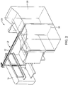
- FIG. 2 shows all three hanging panels 28 stowed within the monument 26.
- FIG. 3 shows two of the hanging panels 28 deployed, at least partially, and the third hanging 28 panel stowed.
- the multi-panel privacy assembly 22 generally includes an elongated overhead beam 32 with at least one track.
- the aft end of the elongated beam 32 also referred to herein as the "storage end,” is the beam end where the hanging panels 28 are stowed.
- the forward end of the beam also referred to herein as the “deployed end,” is farthest from the passenger seats 24.
- the gear arrangement for driving panel motion may be housed at the forward end of the elongated beam 32, for example, in a housing 34 that may be part of the passenger seat arrangement 20, part of an adjacent seat arrangement, part of a monument, etc.
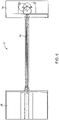
- FIGS. 4-7 show the general components of the multi-panel privacy (screen) assembly 22 according to an embodiment.
- the assembly 22 may be utilized with any passenger seat arrangement or other cabin configuration where it is desired to selectively divide adjacent spaces. Positioning the elongated beam 32 overhead positions the panel tracks above the passengers and obviates the need for floor tracks.
- FIG. 4 shows alcoves 36 defined in the backside of the monument 26 that may function as storage space or other use within the cabin.
- the hanging panels 28 in their stowed positions occupy a small percentage of the monument interior space, leaving space to each side of the stowed hanging panels 28 for storage or other use.
- the monument and housing walls may be constructed from any materials and may be upholstered and/or padded, and generally serve to contain and conceal the drive mechanism of the multi-panel privacy assembly 22 discussed further below.
- FIGS. 8-10 show the multi-panel privacy screen assembly 22 generally including the elongated overhead beam 32 having a plurality of tracks 38, the plurality of hanging panels 28, and the drive mechanism 40 operable for driving a plurality of driven cables 42 or belts to move the plurality of hanging panels 28 along at least one of the plurality of tracks.
- the plurality of hanging panels 28 When fully stowed, the plurality of hanging panels 28 are in a stacked arrangement on separate ones of the plurality of tracks 38. When fully deployed, the plurality of hanging panels 28 are inline along one of the plurality of tracks.
- the drive mechanism 40 is disposed below the forward end of the elongated beam 32. As such, from the drive mechanism 40, the driven cables 42 are routed horizontally, then guided vertically, and finally guided horizontally to engage with their respective hanging panel 28. In other arrangements the drive mechanism may be located elsewhere and consequently other guiding arrangements are envisioned.
- the plurality of tracks 38 includes a first track 44, a second track 46, and a third track 48.
- the first track 44 spans substantially the length of the elongated beam 32.
- the second track 46 is disposed at the storage end of the assembly and has a linear track portion 50 parallel with the first track 44 and a curved track end 52 transitioning the second track 46 into the first track 44.
- the third track 48 is also disposed at the storage end of the assembly and also has a linear track portion 50 parallel with the first track 44 and a curved track end 52 transitioning the third track 48 into the first track 44.
- the first track 44 is disposed between the second and third tracks 46, 48 such that the second and third tracks transition into the first track from opposing sides of the first track.
- a shroud 53 may be disposed along the bottom of the elongated beam 32 to conceal the underside of the elongated beam from view from below.
- the plurality of hanging panels includes a first panel 54, a second panel 56, and a third panel 58, wherein the first panel 54 travels along the first track 44 between stowed and deployed positions of the first panel, the second panel 56 travels along the second and first tracks 46, 44 between the stowed and deployed positions of the second panel, and the third panel 58 travels along the third and first 48, 44 tracks between the stowed and deployed positions of the third panel.
- the first, second and third hanging panels 54, 56, 58 may deploy according to a predetermined sequence in which the first panel 54 deploys first, the second panel 56 deploys second, and the third panel 58 deploys third.
- the second and third tracks 46, 48 and a portion of the first track 44 coincident with the second and third tracks are disposed within the storage area positioned aft of the passenger seats.
- the first panel 54 hangs from the first track 44
- the second panel 56 hangs from the second track 46
- the third panel 58 hangs from the third track 48 (see FIG. 14 ).
- the hanging panels 54, 56, 58 deploy horizontally, the first panel 54 deploys along the first track 44, the second panel 56 transitions from the second track 46 to the first track 44, and the third panel 58 transitions from the third track 48 to the first track, such that the hanging panels are stacked hanging from their respective tracks when fully stowed and are inline along the first track 44 when fully deployed.
- the hanging panels 54, 56, 58 move horizontally in the reverse order when stowing.
- the second and third hanging panels 56, 58 may be guided to their respective second and third tracks 46, 48 to be stowed using a guiding means such as mechanical guiding, magnetic attraction, etc.
- FIG. 11 shows a portion of the storage end of the elongated beam 32.
- Coupling members 60 are operable for suspending each of the first, second and third hanging panels 54, 56, 58 from the elongated beam 32.
- One or more coupling members 60 may be coupled to each hanging panel, for example connecting to an elongate C-shaped member 62 attached along the top of each panel, to stabilize the panel and minimize swing.
- Each coupling member 60 generally has a first end 64 coupled to a top edge of its respective hanging panel, a second end 66 coupled to one of a plurality of driven cables 42, and rollers 68 rollable along their respective one(s) of the first, second and third tracks 44, 46, 48.
- the coupling members 60 may be coupled to their respective driven cable 42 utilizing a set screw 70 tightened against the cable passing through a post hole 72.
- Cable pulleys 74 at the storage end may be used to guide and organize the various loops of driven cable 42, with each driven loop operable for driving the motion of one of the hanging panels 54, 56, 58.
- vertically oriented pulleys may be used to guide the first driven cable 76 driving the first hanging panel 54
- horizontally and angled oriented pulleys may be used to guide the second driven cable 78 driving the second hanging panel 56
- horizontally and angled oriented pulleys may be used to guide the third driven cable 80 driving the third hanging panel 58.
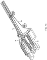
- FIGS. 12-14 show the storage end of the elongated beam 32, and particularly cable tensioners 82, with one cable tensioner associated with each driven cable 42.
- Each cable tensioner 82 is operably coupled to one of the plurality of driven cables 76, 78, 80.
- Each cable tensioner 82 includes a spring 84 affixed at one end to a static element 86 such as a plate affixed atop the elongated beam 32, and at an opposing end coupled to one of the driven cables 76, 78, 80.
- the cable tensioners 82 may function to apply a pulling force and shock absorption.
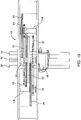
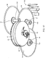
- FIGS. 15-17 show an exemplary drive mechanism for driving panel deployment.
- the driven cables are driven by an intermittent gear assembly 88 that may generally include a motor driven shaft 90, a plurality of intermittent driver gears 92, a plurality of driven gears 94, and a plurality of cable pulleys 96.
- the motor driven shaft 90 is driven by a motor 98, which may be affixed to the bottom of the gear box and coupled to the motor driven shaft 90 through a worm gear or other arrangement.
- the plurality of intermittent driver gears 92 are rotatably coupled to the motor-driven shaft 90, and the number of intermittent driver gears corresponds to the number of hanging panels of the assembly.
- the plurality of driven gears 94 are each meshed with one of the plurality of intermittent driver gears 92 and are rotatably coupled to a driven shaft 100, wherein the number of driven gears and shafts corresponds to the number of intermittent driver gears 92.
- the plurality of pulleys 96 are each rotatably coupled to one of the plurality of driven shafts 100, and the number of pulleys corresponds to the number of driven gears. In this configuration, each of the plurality of pulleys 96 is configured to drive motion of one of the plurality of driven cables coupled to one of the plurality of hanging panels 54, 56, 58.
- Each of the plurality of intermittent driver gears 92 has a predetermined tooth configuration and relative fixed position on the motor-driven shaft 90 with respect to the other ones of the plurality of intermittent driver gears to deploy the plurality of hanging panels according to a predetermined deployment sequence.
- the intermittent driver gears 92 may be arranged and configured to first deploy the first hanging panel, followed by deploying the second hanging panel, followed by deploying the third hanging panel.
- Deployment sequences may include, but are not limited to, linking two panels to deploy in sequence with a delay in deploying the third panel, deploying each panel separately with a delay between deployments, deploying all panels in sequence with no delay between deployments, deploying only one panel for TTOL, deploying two panels for TTOL, deploying all three panels for TTOL, etc.
- Deployment may be controlled by the intermittent gear assembly configuration and communication with a control system operable for activating the motor and motor direction according to the predetermined deployment sequence.
- the drive mechanism including the intermittent gear assembly may include first, second and third intermittent driver gears rotatably coupled to the motor-driven shaft, wherein the first, second and third intermittent driver gears correspond to the first, second and third hanging panels, respectively.
- the assembly may further include first, second and third driven gears rotatably coupled to respective first, second and third driven shafts, wherein the first, second and third driven gears are meshed with the respective first, second and third intermittent driver gears.
- the assembly may further include first, second and third drive pulleys rotatably coupled to the respective first, second and third driven shafts, wherein each of the plurality of pulleys is configured to drive motion of one of the plurality of driven cables.
- Directional pulleys 102 configured to guide a directional change of the plurality of driven cables (not shown) extending between the drive mechanism and the plurality of hanging panels.
- Directional pulleys 102 may be provided in pairs in a plane of their respective cable pulley 96 to guide the cables, for example, to provide a vertical to horizontal directional change or vice versa.
- FIG. 18 shows an alternative drive mechanism, which is not part of the current invention, utilizing an endless belt configuration wherein one of the panels is coupled to an endless belt 104 operable for driving panel deployment.
- FIG. 19 shows another alternative drive mechanism, which is not part of the current invention, utilizing an endless cable configuration wherein one of the panels is coupled to an endless cable 106 operable for driving panel deployment.
- FIGS. 20A-22B the embodiments shown in FIGS. 18 and 19 may utilize panel arrangements wherein a leading hanging panel serves to deploy a following hanging panel and so on.
- the panels are linked such that when the first panel deployed reaches an engagement position that panel engages a following panel to pull the following panel, and so on.
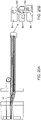
- FIG. 20A shows a stacked track configuration and the storage end of the elongated beam 32
- FIG. 20B shows a detailed view of spring-loaded lever arms 108 that engage pins on following panels to link panel deployment.
- the first hanging panel 54 carries a spring-loaded lever arm 108 that engages a pin atop the second hanging panel 56 when the first hanging panel reaches a predetermined relative position to the second hanging panel
- the second hanging panel 56 carries a spring-loaded lever arm 108 that engages a pin atop the third hanging panel 58 when the second hanging panel reaches a predetermined relative position to the third second hanging panel.
- FIGS. 21A and 21B show a panel deployment sequence and spring-loaded lever arm and pin engagement of the first and second hanging panels 54, 56.
- FIGS. 22A and 22B show full panel deployment inline and spring-loaded lever arm 108 and pin engagement of the first and second hanging panels 54, 56, and of the second and third hanging panels 56, 58.
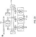
- FIGS. 23 and 24 show another embodiment, which is not part of the current invention, for hanging panel deployment utilizing cam tracks 110, panel tracks 112, and tracks 114 to connect the cam and panel tracks.
- the cams may include three individual tracks that guide the hanging panels to slide in line with the first or center hanging panel on a main track 116.
Landscapes
- Engineering & Computer Science (AREA)
- Mechanical Engineering (AREA)
- Aviation & Aerospace Engineering (AREA)
- Power-Operated Mechanisms For Wings (AREA)
Claims (14)
- Privatsphäre Schutzanordnung (22) aus mehrere Paneele zur Verwendung in einer Passagiersitzanordnung (20), umfassend lateral angrenzende Passagiersitze (24), wobei die Folgendes umfasst:einen länglichen Überkopfträger(32) mit mehreren Schienen (38; 44, 46, 48);mehrere hängende Paneele (28; 54, 56, 58);mehrere angetriebene Seilzüge (42; 76, 78, 80);Kopplungselemente (60), die jedes der mehreren hängenden Paneele (28; 54, 56, 58) am länglichen Überkopfträger (32) aufhängen, wobei jedes Kopplungselement (60) ein erstes Ende (64), gekoppelt nahe einer oberen Kante eines der mehreren hängenden Paneele (28; 54, 56, 58), ein zweites Ende (66), gekoppelt mit einem der mehreren angetriebenen Seilzüge (42; 76, 78, 80), und Rollen (68), die entlang zumindest einer der mehreren Schienen (38; 44, 46, 48) rollbar sind, aufweist;wobei, wenn vollständig verstaut, die mehreren hängenden Paneele in einer gestapelten Anordnung auf voneinander getrennten der mehreren Schienen befindlich sind, und wenn vollständig ausgefahren, die mehreren hängenden Paneele in einer Linie entlang einer der mehreren Schienen befindlich sind;wobei die Privatsphäre Schutzanordnung (22) aus mehrere Paneele einen Antriebsmechanismus (40) umfasst, der betreibbar ist zum Antreiben der angetriebenen Seilzüge (42; 76, 78, 80) zum Bewegen der mehreren hängenden Paneele (28; 54, 56, 58) entlang zumindest einer der mehreren Schienen (38; 44, 46, 48); und wobeider Antriebsmechanismus (40) eine intermittierende Getriebeanordnung (88) umfasst, betreibbar zum Antreiben der mehreren angetriebenen Seilzüge (42; 76, 78, 80) zum Bewegen der der mehreren hängenden Paneele (28; 54, 56, 58) entlang zumindest einer der mehreren Schienen (38; 44, 46, 48) entsprechend einer vorbestimmten Ausfahrsequenz.
- Privatsphäre Schutzanordnung aus mehrere Paneele nach Anspruch 1, wobei jeder der angetriebenen Seilzüge (42; 76, 78, 80) mit einem der mehreren hängenden Paneele (28; 54, 56, 58) gekoppelt ist.
- Privatsphäre Schutzanordnung aus mehrere Paneele nach Anspruch 1 oder 2, wobei die mehreren Schienen (38; 44, 46, 48) Folgendes umfassen:eine erste Schiene (44), die im Wesentlichen die Länge des länglichen Überkopfträgers (32) überspannt;eine zweite Schiene (46), angeordnet an einem Verstauungsende der Privatsphäre Schutzanordnung (22) aus mehrere Paneele, wobei die zweite Schiene (46) einen linearen Schienenteil (50) parallel zur ersten Schiene (44) und ein gebogenes Schienenende (52), das die zweite Schiene (46) in die erste Schiene (44) überführt, aufweist; undeine dritte Schiene (48), angeordnet an einem Verstauungsende der Privatsphäre Schutzanordnung (22) aus mehrere Paneele, wobei die dritte Schiene (48) einen linearen Schienenteil (50) parallel zur ersten Schiene (44) und ein gebogenes Schienenende (52), das die dritte Schiene (48) in die erste Schiene (44) überführt, aufweist.
- Privatsphäre Schutzanordnung aus mehrere Paneele nach Anspruch 3, wobei die erste Schiene (44) zwischen der zweiten (46) und der dritten (48) Schiene angeordnet ist, sodass die zweite und die dritte Schiene (46, 48) von einander gegenüberliegenden Seiten der ersten Schiene (44) in die erste Schiene (44) übergehen.
- Privatsphäre Schutzanordnung aus mehrere Paneele nach einem oder mehreren der Ansprüche 3-4, wobei die mehreren hängenden Paneele ein erstes Paneel (54), ein zweites Paneel (56) und ein drittes Paneel (58) umfassen, wobei das erste Paneel (54) entlang der ersten Schiene (44) zwischen einer verstauten und ausgefahrenen Position des ersten Paneels (54) fährt, das zweite Paneel (56) entlang der zweiten und der ersten Schiene (44, 46) zwischen der verstauten und der ausgefahrenen Position des zweiten Paneels (56) fährt und das dritte Paneel (58) entlang der dritten und der ersten Schiene (48, 44) zwischen der verstauten und der ausgefahrenen Position des dritten Paneels (58) fährt.
- Privatsphäre Schutzanordnung aus mehrere Paneele nach Anspruch 5, wobei das erste, zweite und dritte hängende Paneel (54, 56, 58) entsprechend der vorbestimmten Ausfahrsequenz ausfahren, bei der das erste Paneel (54) als erstes ausfährt, das zweite Paneel (56) als zweites ausfährt und das dritte Paneel (58) als drittes ausfährt.
- Privatsphäre Schutzanordnung aus mehrere Paneele nach einem oder mehreren der Ansprüche 3-6, wobei die zweite und die dritte Schiene (46, 48) und ein Teil der ersten Schiene (44), der mit der zweiten und der dritten Schiene (46, 48) zusammenfällt, innerhalb eines Verstauungsbereichs angeordnet sind, der dazu angepasst ist, hinter lateral angrenzenden Passagiersitzen (24) positioniert zu werden, die durch die mehreren hängenden Paneele (28; 54, 56, 58) getrennt werden sollen.
- Privatsphäre Schutzanordnung aus mehrere Paneele nach einem oder mehreren der Ansprüche 1-7, wobei die intermittierende Getriebeanordnung (88) Folgendes umfasst:
eine motorgetriebene Welle (90);mehrere intermittierende Antriebszahnräder (92), drehbar mit der motorgetriebenen Welle (90) gekoppelt, wobei die Anzahl von intermittierenden Antriebszahnrädern (92) der Anzahl von hängenden Paneelen (28; 54, 56, 58) entspricht;mehrere angetriebene Zahnräder (94), jeweils mit einem der mehreren intermittierenden Antriebszahnräder (92) ineinandergreifend, wobei jedes der mehreren angetriebenen Zahnräder (94) drehbar mit einer angetriebenen Welle (100) gekoppelt ist, wobei die Anzahl von angetriebenen Zahnrädern (94) der Anzahl von intermittierenden Antriebszahnrädern (92) entspricht; undmehrere Riemenscheiben (96), wobei jede Riemenscheibe (96) drehbar mit einer der mehreren angetriebenen Wellen (100) gekoppelt ist, und wobei die Anzahl von Riemenscheiben (96) der Anzahl von angetriebenen Zahnrädern (94) entspricht;wobei jede der mehreren Riemenscheiben (96) dazu ausgelegt ist, Bewegung von einem der mehreren angetriebenen Seilzüge (42; 76, 78, 80), jeweils gekoppelt mit einem der mehreren hängenden Paneele (28; 54, 56, 58), anzutreiben. - Privatsphäre Schutzanordnung aus mehrere Paneele nach Anspruch 8, wobei jedes der mehreren intermittierenden Antriebszahnräder (92) eine vorbestimmte Zahnauslegung und eine relativ feste Position an der motorgetriebenen Welle (90) bezüglich der anderen der mehreren intermittierenden Antriebsräder (92) aufweist, um die mehreren hängenden Paneele (28; 54, 56, 58) entsprechend der vorbestimmten Ausfahrsequenz auszufahren.
- Privatsphäre Schutzanordnung nach einem oder mehreren der Ansprüche 1-9, ferner umfassend zumindest eine Menge von gerichteten Riemenscheiben (102), dazu ausgelegt, eine Richtungsänderung der mehreren angetriebenen Seilzüge (42; 76, 78, 80) zu führen, die sich zwischen dem Antriebsmechanismus (40) und den mehreren hängenden Paneelen (28; 54, 56, 58) erstrecken.
- Privatsphäre Schutzanordnung aus mehrere Paneele nach einem oder mehreren der Ansprüche 1-10, ferner umfassend mehrere Seilzugspanner (82), jeweils wirkgekoppelt mit einem der mehreren angetriebenen Seilzüge (42; 76, 78, 80), wobei jeder Seilzugspanner (82) eine Feder (84) umfasst, die an einem Ende an einem statischen Element (86) befestigt ist und an einem gegenüberliegenden Ende mit einem der mehreren angetriebenen Seilzüge (42; 76, 78, 80) gekoppelt ist.
- Privatsphäre Schutzanordnung aus mehrere Paneele nach einem oder mehreren der vorhergehenden Ansprüche, wenn abhängig von Anspruch 5,wobei die mehreren angetriebenen Seilzüge (42) einen ersten angetriebenen Seilzug (76), der Bewegung des ersten hängenden Paneels (54) antreibt, einen zweiten angetriebenen Seilzug (78), der Bewegung des zweiten hängenden Paneels (56) antreibt, und einen dritten angetriebenen Seilzug (80), der Bewegung des dritten hängenden Paneels (58) antreibt, umfasst; undwobei der Antriebsmechanismus (40) betreibbar ist zum Antreiben des ersten, zweiten und dritten Seilzugs (76, 78, 80) zum Bewegen des entsprechenden ersten, zweiten und dritten hängenden Paneels (54, 56, 58) entlang zumindest einer der ersten, zweiten und dritten Schiene (44, 46, 48) zwischen ausgefahrenen und verstauten Positionen.
- Passagiersitzanordnung, umfassend erste und zweite lateral angrenzende Passagiersitze (24), ein erstes Monument (26), positioniert hinter den ersten und zweiten lateral angrenzenden Passagiersitzen (24), ein zweites Monument (34), positioniert vor den ersten und zweiten lateral angrenzenden Passagiersitzen (24), und die Privatsphäre Schutzanordnung (22) aus mehrere Paneele nach einem oder mehreren der vorhergehenden Ansprüche.
- Passagiersitzanordnung nach Anspruch 13, wobei:die mehreren hängenden Paneele (28; 54, 56, 58), wenn vollständig verstaut in der gestapelten Anordnung, innerhalb des ersten Monuments (26) positioniert sind; wobei die intermittierende Getriebeanordnung (88) innerhalb des zweiten Monuments (34) angeordnet ist; unddie mehreren hängenden Paneele (28; 54, 56, 58) ausfahren, um eine Teilungswand zwischen zumindest einem Teil der ersten und zweiten lateral angrenzenden Passagiersitze (24) zu bilden.
Applications Claiming Priority (1)
| Application Number | Priority Date | Filing Date | Title |
|---|---|---|---|
| US16/173,395 US10946966B2 (en) | 2018-10-29 | 2018-10-29 | Multi-panel privacy screen assembly |
Publications (2)
| Publication Number | Publication Date |
|---|---|
| EP3647196A1 EP3647196A1 (de) | 2020-05-06 |
| EP3647196B1 true EP3647196B1 (de) | 2022-08-17 |
Family
ID=68342835
Family Applications (1)
| Application Number | Title | Priority Date | Filing Date |
|---|---|---|---|
| EP19205151.4A Active EP3647196B1 (de) | 2018-10-29 | 2019-10-24 | Mehrpaneel-sichtschutzanordnung |
Country Status (2)
| Country | Link |
|---|---|
| US (1) | US10946966B2 (de) |
| EP (1) | EP3647196B1 (de) |
Families Citing this family (13)
| Publication number | Priority date | Publication date | Assignee | Title |
|---|---|---|---|---|
| FR3081835B1 (fr) * | 2018-06-05 | 2021-04-09 | Zodiac Seats France | Arrangement de sieges, notamment d'un avion |
| US10946966B2 (en) * | 2018-10-29 | 2021-03-16 | B/E Aerospace, Inc. | Multi-panel privacy screen assembly |
| US11077947B2 (en) * | 2019-11-15 | 2021-08-03 | B/E Aerospace, Inc. | Suite bridge with privacy panel |
| US11691732B2 (en) | 2020-07-10 | 2023-07-04 | B/E Aerospace, Inc. | Modular multiple-egress doors for dual occupancy aircraft passenger suites |
| GB2596873B (en) * | 2020-07-10 | 2023-07-19 | Thompson Aero Seating Ltd | Actuation system |
| US11708163B2 (en) | 2020-10-02 | 2023-07-25 | B/E Aerospace, Inc. | Static aircraft seat privacy panels |
| US12049319B2 (en) | 2020-10-02 | 2024-07-30 | B/E Aerospace, Inc. | Slanted aircraft seat privacy panels |
| US11613360B2 (en) * | 2021-01-29 | 2023-03-28 | B/E Aerospace, Inc. | Actuatable door for an aircraft passenger suite |
| US11919392B2 (en) * | 2021-09-21 | 2024-03-05 | GM Global Technology Operations LLC | Rollable/bendable virtual 3D display |
| US11800082B2 (en) | 2021-09-21 | 2023-10-24 | GM Global Technology Operations LLC | Virtual 3D display |
| WO2023057440A1 (en) * | 2021-10-04 | 2023-04-13 | Ali Ersan | Seating system for an aircraft |
| CN119451891A (zh) * | 2022-06-27 | 2025-02-14 | 新加坡航空公司 | 飞行器座舱 |
| US12240609B2 (en) | 2022-07-12 | 2025-03-04 | B/E Aerospace, Inc. | Cascading privacy divider |
Family Cites Families (38)
| Publication number | Priority date | Publication date | Assignee | Title |
|---|---|---|---|---|
| US2657436A (en) * | 1951-08-14 | 1953-11-03 | John T Fairhurst | Sliding partition |
| US2944282A (en) * | 1959-08-17 | 1960-07-12 | Greco Michael | Concealable partitions |
| US3235915A (en) * | 1961-06-06 | 1966-02-22 | Hauserman Co E F | Sliding panel partition |
| US3425160A (en) * | 1967-11-14 | 1969-02-04 | Emil M Petterborg | Sliding doors on single track |
| US3577679A (en) * | 1970-05-18 | 1971-05-04 | Emil M Petterborg | Multiple automatically retractable and extensible sliding doors in planar alignment |
| FI78962C (fi) * | 1987-12-09 | 1989-10-10 | Lemminkaeinen Oy | Svaengbara glas foer balkong. |
| US5016318A (en) * | 1989-07-13 | 1991-05-21 | Panelfold, Inc. | Multi-directional radial wheel trolley and track for operable walls |
| JPH0723668B2 (ja) * | 1989-08-31 | 1995-03-15 | 東洋エクステリア株式会社 | 積層状折畳み戸の戸袋装置 |
| JPH0759859B2 (ja) * | 1989-08-31 | 1995-06-28 | 東洋エクステリア株式会社 | スライドパネルの安定開閉装置 |
| US5230123A (en) * | 1989-12-21 | 1993-07-27 | Hufcor, Inc. | Operable wall deployment and storage system |
| US5329857A (en) * | 1992-12-22 | 1994-07-19 | Modernfold, Inc. | Track switch for suspended movable wall panels |
| DE4424660C1 (de) * | 1994-07-14 | 1995-09-28 | Dorma Gmbh & Co Kg | Vorrichtung und Verfahren für den Betrieb eines automatischen Trennwandsystems |
| US5794381A (en) | 1995-12-22 | 1998-08-18 | Ricon Corporation | Selectively engageable motor drive assembly |
| JPH11510870A (ja) * | 1996-06-21 | 1999-09-21 | ドルマ ゲゼルシャフト ミット ベシュレンクテル ハフツング ウント コンパニー コマンディートゲゼルシャフト | スライド壁 |
| DE19734179C2 (de) * | 1997-08-07 | 1999-09-02 | Dorma Gmbh & Co Kg | An mindestens einer Laufschiene geführte Schiebewand |
| DE10001419B4 (de) * | 1999-01-16 | 2016-12-01 | Geze Gmbh | Türanlage |
| EP1226326A1 (de) * | 1999-11-03 | 2002-07-31 | Modernfold, Inc. | Automatische führungsschienen- und weichenanordnung für verstellbare wandelemente |
| ES2253507T5 (es) * | 2002-04-23 | 2010-02-18 | Hawa Ag | Dispositivo para la sujecion de placas y elemento separador. |
| US7185589B2 (en) * | 2002-06-26 | 2007-03-06 | Modernfold, Inc. | Multi-program trolleys and switches |
| WO2004022894A1 (en) | 2002-09-03 | 2004-03-18 | Rytec Corporation | Dual overhead track for a sliding door |
| US20050210752A1 (en) * | 2004-03-15 | 2005-09-29 | Schulte Peter S | Drive tension sensor for a powered door |
| EP1657393B1 (de) * | 2004-11-12 | 2014-03-19 | Hawa Ag | Vorrichtung mit steuerbaren Trennelementen und Steuerverfahren |
| WO2007106824A2 (en) | 2006-03-14 | 2007-09-20 | 3Form, Inc. | Sliding panel system |
| WO2008113178A1 (en) | 2007-03-21 | 2008-09-25 | Magna Closures Inc. | Belt driven power sliding door with belt tensioner |
| DE102009038014A1 (de) * | 2009-08-20 | 2011-02-24 | Dorma Gmbh + Co. Kg | Laufschiene für eine Schiebewand und Verfahren zur Betätigung einer Weiche in einer Laufschiene |
| US8579006B2 (en) * | 2009-10-19 | 2013-11-12 | Adrian Mario Levin | Space divider system |
| ES2919854T3 (es) | 2009-10-26 | 2022-07-28 | Panoramic Doors Llc | Estructura de puerta corredera con puertas correderas y puertas pivotantes |
| US20110138692A1 (en) | 2009-12-16 | 2011-06-16 | Intradoor Inc. | Automatic sliding door system |
| US10196815B2 (en) * | 2014-05-28 | 2019-02-05 | Advanced Equipment Corporation | Wall partition movement systems and methods |
| US10231563B2 (en) * | 2015-07-08 | 2019-03-19 | The Boeing Company | Integrated curtain system and method |
| FR3039581B1 (fr) * | 2015-07-31 | 2017-07-28 | Faiveley Transp Tours | Systeme de guidage et de support d'un vantail de porte paliere de quai |
| WO2017066559A1 (en) * | 2015-10-14 | 2017-04-20 | B/E Aerospace, Inc. | Aircraft passenger suite privacy screen control apparatus and method |
| US10494858B2 (en) * | 2016-02-03 | 2019-12-03 | Rite-Hite Holding Corporation | Insulated doors with restorable breakaway sections |
| WO2017176726A1 (en) * | 2016-04-04 | 2017-10-12 | B/E Aerospace, Inc. | Aircraft interior surface and method of illuminating an aircraft interior surface |
| US20180044966A1 (en) * | 2016-08-14 | 2018-02-15 | Slider Next Vision Ltd. | Automatic mechanism for sliding doors or windows |
| US10465383B2 (en) * | 2017-01-23 | 2019-11-05 | Advanced Equipment Corporation | Panel storage system and devices |
| US10077588B1 (en) * | 2017-06-16 | 2018-09-18 | Gregory A Header | Path guide for movable partition assemblies |
| US10946966B2 (en) * | 2018-10-29 | 2021-03-16 | B/E Aerospace, Inc. | Multi-panel privacy screen assembly |
-
2018
- 2018-10-29 US US16/173,395 patent/US10946966B2/en active Active
-
2019
- 2019-10-24 EP EP19205151.4A patent/EP3647196B1/de active Active
Also Published As
| Publication number | Publication date |
|---|---|
| EP3647196A1 (de) | 2020-05-06 |
| US20200130840A1 (en) | 2020-04-30 |
| US10946966B2 (en) | 2021-03-16 |
Similar Documents
| Publication | Publication Date | Title |
|---|---|---|
| EP3647196B1 (de) | Mehrpaneel-sichtschutzanordnung | |
| US11345476B2 (en) | Arrangements for aircraft passenger cabins with privacy divider configurations | |
| US10023315B2 (en) | Passenger seat table assembly | |
| EP2879907B1 (de) | Passagiersitzgarnituranordnung mit beweglichem monitor | |
| CA2868186C (en) | Cantilevered tray table and aircraft passenger suite including the same | |
| US5816534A (en) | Aircraft cabin divider arrangement | |
| US9266614B2 (en) | Passenger suite seating arrangement with moveable video monitor | |
| EP3174789B1 (de) | Sitzanordnung mit beweglichem videomonitor für insassenraum | |
| US20140300148A1 (en) | Vertically stowed tray table assembly with translational movement | |
| US20160052633A1 (en) | Passenger module and seating array for an aircraft cabin | |
| CN113353266A (zh) | 带有竖直平移靠背的可收起座舱乘务员座椅 | |
| WO2014155353A1 (en) | Seating array for an aircraft cabin | |
| US10543922B2 (en) | Flight attendant seat, system comprising flight attendant seat as well as arrangement and aircraft area comprising system | |
| EP2783983A1 (de) | Fahrgastmodul für eine Sitzanordnung einer Flugzeugkabine | |
| EP2783984A1 (de) | Sitzanordnung für eine Flugzeugkabine | |
| US20250313337A1 (en) | Full-height divider curtain between aircraft cabin passenger suites | |
| GB2513554A (en) | Passenger module for a seating array for an aircraft cabin |
Legal Events
| Date | Code | Title | Description |
|---|---|---|---|
| PUAI | Public reference made under article 153(3) epc to a published international application that has entered the european phase |
Free format text: ORIGINAL CODE: 0009012 |
|
| STAA | Information on the status of an ep patent application or granted ep patent |
Free format text: STATUS: THE APPLICATION HAS BEEN PUBLISHED |
|
| AK | Designated contracting states |
Kind code of ref document: A1 Designated state(s): AL AT BE BG CH CY CZ DE DK EE ES FI FR GB GR HR HU IE IS IT LI LT LU LV MC MK MT NL NO PL PT RO RS SE SI SK SM TR |
|
| AX | Request for extension of the european patent |
Extension state: BA ME |
|
| STAA | Information on the status of an ep patent application or granted ep patent |
Free format text: STATUS: REQUEST FOR EXAMINATION WAS MADE |
|
| 17P | Request for examination filed |
Effective date: 20201102 |
|
| RBV | Designated contracting states (corrected) |
Designated state(s): AL AT BE BG CH CY CZ DE DK EE ES FI FR GB GR HR HU IE IS IT LI LT LU LV MC MK MT NL NO PL PT RO RS SE SI SK SM TR |
|
| STAA | Information on the status of an ep patent application or granted ep patent |
Free format text: STATUS: EXAMINATION IS IN PROGRESS |
|
| 17Q | First examination report despatched |
Effective date: 20210617 |
|
| GRAP | Despatch of communication of intention to grant a patent |
Free format text: ORIGINAL CODE: EPIDOSNIGR1 |
|
| STAA | Information on the status of an ep patent application or granted ep patent |
Free format text: STATUS: GRANT OF PATENT IS INTENDED |
|
| INTG | Intention to grant announced |
Effective date: 20220429 |
|
| RIN1 | Information on inventor provided before grant (corrected) |
Inventor name: LAWRENCE, ROBERT J. Inventor name: KUYPER, JOHN R. Inventor name: GOVEA BRAVO, SHIRLEY E. Inventor name: FROST, IAN L. |
|
| GRAS | Grant fee paid |
Free format text: ORIGINAL CODE: EPIDOSNIGR3 |
|
| GRAA | (expected) grant |
Free format text: ORIGINAL CODE: 0009210 |
|
| STAA | Information on the status of an ep patent application or granted ep patent |
Free format text: STATUS: THE PATENT HAS BEEN GRANTED |
|
| AK | Designated contracting states |
Kind code of ref document: B1 Designated state(s): AL AT BE BG CH CY CZ DE DK EE ES FI FR GB GR HR HU IE IS IT LI LT LU LV MC MK MT NL NO PL PT RO RS SE SI SK SM TR |
|
| REG | Reference to a national code |
Ref country code: CH Ref legal event code: EP |
|
| REG | Reference to a national code |
Ref country code: DE Ref legal event code: R096 Ref document number: 602019018322 Country of ref document: DE |
|
| REG | Reference to a national code |
Ref country code: IE Ref legal event code: FG4D |
|
| REG | Reference to a national code |
Ref country code: AT Ref legal event code: REF Ref document number: 1512022 Country of ref document: AT Kind code of ref document: T Effective date: 20220915 |
|
| REG | Reference to a national code |
Ref country code: NL Ref legal event code: MP Effective date: 20220817 |
|
| REG | Reference to a national code |
Ref country code: LT Ref legal event code: MG9D |
|
| PG25 | Lapsed in a contracting state [announced via postgrant information from national office to epo] |
Ref country code: SE Free format text: LAPSE BECAUSE OF FAILURE TO SUBMIT A TRANSLATION OF THE DESCRIPTION OR TO PAY THE FEE WITHIN THE PRESCRIBED TIME-LIMIT Effective date: 20220817 Ref country code: RS Free format text: LAPSE BECAUSE OF FAILURE TO SUBMIT A TRANSLATION OF THE DESCRIPTION OR TO PAY THE FEE WITHIN THE PRESCRIBED TIME-LIMIT Effective date: 20220817 Ref country code: PT Free format text: LAPSE BECAUSE OF FAILURE TO SUBMIT A TRANSLATION OF THE DESCRIPTION OR TO PAY THE FEE WITHIN THE PRESCRIBED TIME-LIMIT Effective date: 20221219 Ref country code: NO Free format text: LAPSE BECAUSE OF FAILURE TO SUBMIT A TRANSLATION OF THE DESCRIPTION OR TO PAY THE FEE WITHIN THE PRESCRIBED TIME-LIMIT Effective date: 20221117 Ref country code: NL Free format text: LAPSE BECAUSE OF FAILURE TO SUBMIT A TRANSLATION OF THE DESCRIPTION OR TO PAY THE FEE WITHIN THE PRESCRIBED TIME-LIMIT Effective date: 20220817 Ref country code: LV Free format text: LAPSE BECAUSE OF FAILURE TO SUBMIT A TRANSLATION OF THE DESCRIPTION OR TO PAY THE FEE WITHIN THE PRESCRIBED TIME-LIMIT Effective date: 20220817 Ref country code: LT Free format text: LAPSE BECAUSE OF FAILURE TO SUBMIT A TRANSLATION OF THE DESCRIPTION OR TO PAY THE FEE WITHIN THE PRESCRIBED TIME-LIMIT Effective date: 20220817 Ref country code: FI Free format text: LAPSE BECAUSE OF FAILURE TO SUBMIT A TRANSLATION OF THE DESCRIPTION OR TO PAY THE FEE WITHIN THE PRESCRIBED TIME-LIMIT Effective date: 20220817 |
|
| REG | Reference to a national code |
Ref country code: AT Ref legal event code: MK05 Ref document number: 1512022 Country of ref document: AT Kind code of ref document: T Effective date: 20220817 |
|
| PG25 | Lapsed in a contracting state [announced via postgrant information from national office to epo] |
Ref country code: PL Free format text: LAPSE BECAUSE OF FAILURE TO SUBMIT A TRANSLATION OF THE DESCRIPTION OR TO PAY THE FEE WITHIN THE PRESCRIBED TIME-LIMIT Effective date: 20220817 Ref country code: IS Free format text: LAPSE BECAUSE OF FAILURE TO SUBMIT A TRANSLATION OF THE DESCRIPTION OR TO PAY THE FEE WITHIN THE PRESCRIBED TIME-LIMIT Effective date: 20221217 Ref country code: HR Free format text: LAPSE BECAUSE OF FAILURE TO SUBMIT A TRANSLATION OF THE DESCRIPTION OR TO PAY THE FEE WITHIN THE PRESCRIBED TIME-LIMIT Effective date: 20220817 Ref country code: GR Free format text: LAPSE BECAUSE OF FAILURE TO SUBMIT A TRANSLATION OF THE DESCRIPTION OR TO PAY THE FEE WITHIN THE PRESCRIBED TIME-LIMIT Effective date: 20221118 |
|
| PG25 | Lapsed in a contracting state [announced via postgrant information from national office to epo] |
Ref country code: SM Free format text: LAPSE BECAUSE OF FAILURE TO SUBMIT A TRANSLATION OF THE DESCRIPTION OR TO PAY THE FEE WITHIN THE PRESCRIBED TIME-LIMIT Effective date: 20220817 Ref country code: RO Free format text: LAPSE BECAUSE OF FAILURE TO SUBMIT A TRANSLATION OF THE DESCRIPTION OR TO PAY THE FEE WITHIN THE PRESCRIBED TIME-LIMIT Effective date: 20220817 Ref country code: ES Free format text: LAPSE BECAUSE OF FAILURE TO SUBMIT A TRANSLATION OF THE DESCRIPTION OR TO PAY THE FEE WITHIN THE PRESCRIBED TIME-LIMIT Effective date: 20220817 Ref country code: DK Free format text: LAPSE BECAUSE OF FAILURE TO SUBMIT A TRANSLATION OF THE DESCRIPTION OR TO PAY THE FEE WITHIN THE PRESCRIBED TIME-LIMIT Effective date: 20220817 Ref country code: CZ Free format text: LAPSE BECAUSE OF FAILURE TO SUBMIT A TRANSLATION OF THE DESCRIPTION OR TO PAY THE FEE WITHIN THE PRESCRIBED TIME-LIMIT Effective date: 20220817 Ref country code: AT Free format text: LAPSE BECAUSE OF FAILURE TO SUBMIT A TRANSLATION OF THE DESCRIPTION OR TO PAY THE FEE WITHIN THE PRESCRIBED TIME-LIMIT Effective date: 20220817 |
|
| REG | Reference to a national code |
Ref country code: DE Ref legal event code: R097 Ref document number: 602019018322 Country of ref document: DE |
|
| PG25 | Lapsed in a contracting state [announced via postgrant information from national office to epo] |
Ref country code: SK Free format text: LAPSE BECAUSE OF FAILURE TO SUBMIT A TRANSLATION OF THE DESCRIPTION OR TO PAY THE FEE WITHIN THE PRESCRIBED TIME-LIMIT Effective date: 20220817 Ref country code: MC Free format text: LAPSE BECAUSE OF FAILURE TO SUBMIT A TRANSLATION OF THE DESCRIPTION OR TO PAY THE FEE WITHIN THE PRESCRIBED TIME-LIMIT Effective date: 20220817 Ref country code: EE Free format text: LAPSE BECAUSE OF FAILURE TO SUBMIT A TRANSLATION OF THE DESCRIPTION OR TO PAY THE FEE WITHIN THE PRESCRIBED TIME-LIMIT Effective date: 20220817 |
|
| REG | Reference to a national code |
Ref country code: CH Ref legal event code: PL |
|
| PLBE | No opposition filed within time limit |
Free format text: ORIGINAL CODE: 0009261 |
|
| STAA | Information on the status of an ep patent application or granted ep patent |
Free format text: STATUS: NO OPPOSITION FILED WITHIN TIME LIMIT |
|
| REG | Reference to a national code |
Ref country code: BE Ref legal event code: MM Effective date: 20221031 |
|
| PG25 | Lapsed in a contracting state [announced via postgrant information from national office to epo] |
Ref country code: LU Free format text: LAPSE BECAUSE OF NON-PAYMENT OF DUE FEES Effective date: 20221024 Ref country code: AL Free format text: LAPSE BECAUSE OF FAILURE TO SUBMIT A TRANSLATION OF THE DESCRIPTION OR TO PAY THE FEE WITHIN THE PRESCRIBED TIME-LIMIT Effective date: 20220817 |
|
| P01 | Opt-out of the competence of the unified patent court (upc) registered |
Effective date: 20230608 |
|
| 26N | No opposition filed |
Effective date: 20230519 |
|
| PG25 | Lapsed in a contracting state [announced via postgrant information from national office to epo] |
Ref country code: LI Free format text: LAPSE BECAUSE OF NON-PAYMENT OF DUE FEES Effective date: 20221031 Ref country code: CH Free format text: LAPSE BECAUSE OF NON-PAYMENT OF DUE FEES Effective date: 20221031 |
|
| PG25 | Lapsed in a contracting state [announced via postgrant information from national office to epo] |
Ref country code: SI Free format text: LAPSE BECAUSE OF FAILURE TO SUBMIT A TRANSLATION OF THE DESCRIPTION OR TO PAY THE FEE WITHIN THE PRESCRIBED TIME-LIMIT Effective date: 20220817 |
|
| PG25 | Lapsed in a contracting state [announced via postgrant information from national office to epo] |
Ref country code: BE Free format text: LAPSE BECAUSE OF NON-PAYMENT OF DUE FEES Effective date: 20221031 |
|
| PG25 | Lapsed in a contracting state [announced via postgrant information from national office to epo] |
Ref country code: IE Free format text: LAPSE BECAUSE OF NON-PAYMENT OF DUE FEES Effective date: 20221024 |
|
| PG25 | Lapsed in a contracting state [announced via postgrant information from national office to epo] |
Ref country code: HU Free format text: LAPSE BECAUSE OF FAILURE TO SUBMIT A TRANSLATION OF THE DESCRIPTION OR TO PAY THE FEE WITHIN THE PRESCRIBED TIME-LIMIT; INVALID AB INITIO Effective date: 20191024 |
|
| PG25 | Lapsed in a contracting state [announced via postgrant information from national office to epo] |
Ref country code: CY Free format text: LAPSE BECAUSE OF FAILURE TO SUBMIT A TRANSLATION OF THE DESCRIPTION OR TO PAY THE FEE WITHIN THE PRESCRIBED TIME-LIMIT Effective date: 20220817 |
|
| PG25 | Lapsed in a contracting state [announced via postgrant information from national office to epo] |
Ref country code: MK Free format text: LAPSE BECAUSE OF FAILURE TO SUBMIT A TRANSLATION OF THE DESCRIPTION OR TO PAY THE FEE WITHIN THE PRESCRIBED TIME-LIMIT Effective date: 20220817 Ref country code: IT Free format text: LAPSE BECAUSE OF FAILURE TO SUBMIT A TRANSLATION OF THE DESCRIPTION OR TO PAY THE FEE WITHIN THE PRESCRIBED TIME-LIMIT Effective date: 20220817 |
|
| PG25 | Lapsed in a contracting state [announced via postgrant information from national office to epo] |
Ref country code: TR Free format text: LAPSE BECAUSE OF FAILURE TO SUBMIT A TRANSLATION OF THE DESCRIPTION OR TO PAY THE FEE WITHIN THE PRESCRIBED TIME-LIMIT Effective date: 20220817 |
|
| PG25 | Lapsed in a contracting state [announced via postgrant information from national office to epo] |
Ref country code: BG Free format text: LAPSE BECAUSE OF FAILURE TO SUBMIT A TRANSLATION OF THE DESCRIPTION OR TO PAY THE FEE WITHIN THE PRESCRIBED TIME-LIMIT Effective date: 20220817 |
|
| PG25 | Lapsed in a contracting state [announced via postgrant information from national office to epo] |
Ref country code: MT Free format text: LAPSE BECAUSE OF FAILURE TO SUBMIT A TRANSLATION OF THE DESCRIPTION OR TO PAY THE FEE WITHIN THE PRESCRIBED TIME-LIMIT Effective date: 20220817 |
|
| PGFP | Annual fee paid to national office [announced via postgrant information from national office to epo] |
Ref country code: GB Payment date: 20250923 Year of fee payment: 7 |
|
| PGFP | Annual fee paid to national office [announced via postgrant information from national office to epo] |
Ref country code: FR Payment date: 20250924 Year of fee payment: 7 |
|
| PGFP | Annual fee paid to national office [announced via postgrant information from national office to epo] |
Ref country code: DE Payment date: 20250923 Year of fee payment: 7 |