EP3647202B1 - Turbotriebwerk-anordnung eines luftfahrzeugs, die einen scharnierdeckel umfasst - Google Patents
Turbotriebwerk-anordnung eines luftfahrzeugs, die einen scharnierdeckel umfasst Download PDFInfo
- Publication number
- EP3647202B1 EP3647202B1 EP19204129.1A EP19204129A EP3647202B1 EP 3647202 B1 EP3647202 B1 EP 3647202B1 EP 19204129 A EP19204129 A EP 19204129A EP 3647202 B1 EP3647202 B1 EP 3647202B1
- Authority
- EP
- European Patent Office
- Prior art keywords
- articulated
- cowl
- nacelle
- turbine engine
- closed position
- Prior art date
- Legal status (The legal status is an assumption and is not a legal conclusion. Google has not performed a legal analysis and makes no representation as to the accuracy of the status listed.)
- Active
Links
Images

Classifications
-
- B—PERFORMING OPERATIONS; TRANSPORTING
- B64—AIRCRAFT; AVIATION; COSMONAUTICS
- B64D—EQUIPMENT FOR FITTING IN OR TO AIRCRAFT; FLIGHT SUITS; PARACHUTES; ARRANGEMENT OR MOUNTING OF POWER PLANTS OR PROPULSION TRANSMISSIONS IN AIRCRAFT
- B64D29/00—Power-plant nacelles, fairings or cowlings
- B64D29/06—Attaching of nacelles, fairings or cowlings
-
- B—PERFORMING OPERATIONS; TRANSPORTING
- B64—AIRCRAFT; AVIATION; COSMONAUTICS
- B64D—EQUIPMENT FOR FITTING IN OR TO AIRCRAFT; FLIGHT SUITS; PARACHUTES; ARRANGEMENT OR MOUNTING OF POWER PLANTS OR PROPULSION TRANSMISSIONS IN AIRCRAFT
- B64D27/00—Arrangement or mounting of power plants in aircraft; Aircraft characterised by the type or position of power plants
- B64D27/40—Arrangements for mounting power plants in aircraft
-
- B—PERFORMING OPERATIONS; TRANSPORTING
- B64—AIRCRAFT; AVIATION; COSMONAUTICS
- B64D—EQUIPMENT FOR FITTING IN OR TO AIRCRAFT; FLIGHT SUITS; PARACHUTES; ARRANGEMENT OR MOUNTING OF POWER PLANTS OR PROPULSION TRANSMISSIONS IN AIRCRAFT
- B64D27/00—Arrangement or mounting of power plants in aircraft; Aircraft characterised by the type or position of power plants
- B64D27/40—Arrangements for mounting power plants in aircraft
- B64D27/402—Arrangements for mounting power plants in aircraft comprising box like supporting frames, e.g. pylons or arrangements for embracing the power plant
-
- B—PERFORMING OPERATIONS; TRANSPORTING
- B64—AIRCRAFT; AVIATION; COSMONAUTICS
- B64D—EQUIPMENT FOR FITTING IN OR TO AIRCRAFT; FLIGHT SUITS; PARACHUTES; ARRANGEMENT OR MOUNTING OF POWER PLANTS OR PROPULSION TRANSMISSIONS IN AIRCRAFT
- B64D27/00—Arrangement or mounting of power plants in aircraft; Aircraft characterised by the type or position of power plants
- B64D27/40—Arrangements for mounting power plants in aircraft
- B64D27/404—Suspension arrangements specially adapted for supporting vertical loads
-
- B—PERFORMING OPERATIONS; TRANSPORTING
- B64—AIRCRAFT; AVIATION; COSMONAUTICS
- B64D—EQUIPMENT FOR FITTING IN OR TO AIRCRAFT; FLIGHT SUITS; PARACHUTES; ARRANGEMENT OR MOUNTING OF POWER PLANTS OR PROPULSION TRANSMISSIONS IN AIRCRAFT
- B64D29/00—Power-plant nacelles, fairings or cowlings
- B64D29/02—Power-plant nacelles, fairings or cowlings associated with wings
-
- B—PERFORMING OPERATIONS; TRANSPORTING
- B64—AIRCRAFT; AVIATION; COSMONAUTICS
- B64D—EQUIPMENT FOR FITTING IN OR TO AIRCRAFT; FLIGHT SUITS; PARACHUTES; ARRANGEMENT OR MOUNTING OF POWER PLANTS OR PROPULSION TRANSMISSIONS IN AIRCRAFT
- B64D29/00—Power-plant nacelles, fairings or cowlings
- B64D29/08—Inspection panels for power plants
Definitions
- the present invention relates to a turbomachine assembly of an aircraft comprising an articulated cowl, as well as to an aircraft comprising such an assembly.
- An aircraft conventionally comprises a fuselage on either side of which a wing is attached.
- Each wing supports at least one attachment mast which in turn supports a turbomachine assembly composed of a nacelle and an engine.
- the nacelle forms the aerodynamic surface that surrounds the engine.
- the attachment mast is fixed between the wing structure and the turbomachine assembly.
- a cover located in the upper part of the nacelle can be removed to access the systems mentioned above and in particular the electrical junctions between the attachment mast and the engine.
- An object of the present invention is to provide a nacelle which comprises a hinged cover which facilitates access to the systems located at the junction between the attachment mast and the engine.
- Such a nacelle therefore facilitates the work of technicians, since the hinged cover can be opened and closed easily and quickly.
- Such an architecture also avoids the phenomena of scooping.
- the articulation comprises at least one connecting rod on the port side and on the starboard side and at least one jack, each of the connecting rods and each jack have a first end mounted articulated on the structure and a second end mounted articulated on the articulated cover.
- the structure comprises on port and starboard sides, a leaf spring on which the first ends of each connecting rod and of each cylinder are articulated.
- the turbomachine assembly comprises, on port and starboard sides of the articulated cowl, a shoe fixed under the upstream cowl, each shoe has a slot which opens onto one of the lateral sides of the shoe and which is open towards the rear, the turbomachine assembly also comprises, for each slot, a centering stud secured to the articulated cowl, and oriented so that when the articulated cowl goes from the open position to the closed position, each centering pin penetrates into the slot and when the hinged cover goes from the closed position to the open position, each centering stud comes out of the slot.
- the invention also proposes an aircraft comprising an attachment pylon and a turbomachine assembly according to one of the preceding variants attached to said attachment pylon.
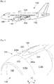
- the Fig. 1 shows an aircraft 100 which has a fuselage 102 on either side of which is fixed a wing 104. Under each wing 104 is fixed a fastening mast 106 to which is attached a turbomachine assembly 108 composed of a nacelle 110 and of an engine (not shown) surrounded by the nacelle 110.
- X denotes the longitudinal axis of the nacelle 110 oriented positively in the direction of travel of the aircraft 100 and which is also parallel to the longitudinal axis of the aircraft 100
- Y is called the transverse axis of the nacelle 110 which is horizontal when the aircraft 100 is on the ground
- Z the vertical axis or vertical height when the aircraft 100 is on the ground
- the Fig. 2 shows the junction between the turbomachine assembly 108 and the attachment mast 106.
- the nacelle 110 comprises a structure (302, Fig. 3 ) and several cowls (or fairings) 110a-b, 200 which are fixed to the structure 302 in order to provide an aerodynamic surface.
- the nacelle 110 comprises an air inlet 109 through which the engine sucks in the air necessary for its operation.
- the nacelle 110 comprises, in particular, in the upper part and in front of the attachment mast 106 (that is to say between the air inlet 109 and the mast 106), an articulated cover 200.
- the articulated cowl 200 is positioned behind an upstream cowl 110a which itself extends rearwardly from the air inlet 109.
- the articulated cowl 200 is positioned between side cowls 110b.
- the hinged cover 200 has four edges 202, 204 and 206a-b which are opposed in pairs.
- the hinged cover 200 more particularly has a front edge 202 which is disposed at the front of the hinged cover 200 with respect to the longitudinal axis X and which is generally parallel to the transverse axis Y.
- the hinged cover 200 more particularly has a rear edge 204 which is disposed at the rear of the hinged cover 200 with respect to the longitudinal axis X and which is also generally parallel to the transverse axis Y.
- the hinged cowl 200 more particularly has two side edges 206a-b which are arranged to port and starboard of the hinged cowl 200 and which are generally parallel to the longitudinal axis X.
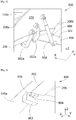
- the Fig. 2 shows the hinged cover 200 in a closed position and the Fig. 3 shows the hinged cover 200 in an open position.
- the hinged cover 200 is shown in transparency (thin dashed lines).
- the articulated cowl 200 is mounted articulated on the structure 302 of the nacelle 110 between the closed position ( Fig. 2 ) in which the articulated cowl 200 is in aerodynamic continuity with the other cowls 110a-b of the nacelle 110 and the open position ( Fig. 3 ) in which the articulated cowl 200 releases an opening in the nacelle 110 in order to access the interior of the nacelle 110 and in particular to the systems of the aircraft 100 which extend between the attachment mast 106 and the engine such as, in particular, an electrical box 350.
- the nacelle 110 has an articulation (500, Fig. 5 ) which is disposed at the front edge 202 and a locking system 400 which is disposed at the rear edge 204.
- the Fig. 5 shows part of an example of an articulation 500 which is fixed between the articulated cowl 200 and the structure 302 of the nacelle 110 and ensures the displacement of the articulated cowl 200 between the closed position and the open position and vice versa.
- the Fig. 4 shows part of an example of a locking system 400.
- the locking system 400 is movable between a locking position in which it blocks the movement of the rear edge 204 relative to the structure 302 of the nacelle 110 and a position unlocking in which it allows movement of the rear edge 204 relative to the structure 302 of the nacelle 110.
- the locking system 400 is actuated by any appropriate means such as for example a handle operable from outside the nacelle 110, or such as for example an electric control.
- the passage from the closed position to the open position of the articulated cowl 200 is effected by tilting the articulated cowl 200 around the articulation 500 and by moving the rear edge 204 towards the outside of the nacelle 110.
- Such an articulated cover 200 thus allows easy and rapid access to the interior of the nacelle 110.
- the front edge 202 is positioned under the upstream cover 110a thus avoiding scooping phenomena.
- the Fig. 4 shows an embodiment of the locking system 400 where the elements of the articulated cover 200 are shown in transparency (thin phantom lines).
- the locking system 400 comprises on port and starboard sides, a centering plate 402 integral with the structure 302 and extending generally horizontally forward, and a bolt 404 operable and movable horizontally on the structure 302.
- the centering plate 402 is pierced with a window 406 having an axis perpendicular to the plane of the centering plate 402.
- the locking system 400 also comprises for each window 406, a centering stud 408 integral with the articulated cover 200 which comes out of the window 406 in the open position and penetrates the window 406 in the closed position, thus ensuring maintenance along the longitudinal axis. X.
- the locking system 400 also comprises, for each bolt 404, a keeper 410 integral with the articulated cover 200 in which the bolt 404 enters the closed position and leaves it in the open position when it is actuated. In the embodiment of the invention presented here, the bolt 404 retracts rearwardly to exit the keeper 410.
- the Fig. 5 shows an articulation 500 according to a particular embodiment of the invention. On the Fig. 5 , only the starboard side is shown.
- the articulation 500 comprises at least one connecting rod 502a-b on the port side and on the starboard side and at least one cylinder 504.
- Each of the connecting rods 502a-b and each actuator 504 have a first end mounted articulated on the structure 302 and a second end mounted articulated on the articulated cover 200.
- the actuator 504 assists the opening of the articulated cover 200 and maintains it in the open position. and is for example a gas spring.
- Such an articulation 500 allows a wide opening of the articulated cowl 200 in order to reach the systems of the aircraft 100.
- the structure 302 comprises on port and starboard sides, a leaf spring 306 on which the first ends of each connecting rod 502a-b and of each cylinder 504 are articulated.
- the Fig. 6 shows the positioning of the front edge 202 of the articulated cover 200 under the upstream cover 110a in the closed position.
- the Fig. 6 also shows a radial centering system 600 which, in the closed position, ensures centering in the radial direction of the nacelle 110 which is here generally vertical.
- the radial centering system 600 comprises on port and starboard sides of the articulated cowl 200, a shoe 602 integral with the structure 302, and here more particularly with the upstream cowl 110. Each shoe 602 is here fixed under the upstream cowl 110a.
- Each shoe 602 has a slot 604 which opens onto one of the lateral flanks of the shoe 602 and which is open towards the rear.
- the slot 604 is therefore delimited upwards and downwards by the walls of the shoe 602, that is to say generally along the vertical axis Z.
- the radial centering system 600 also comprises, for each slot 604, a centering stud 606 which is integral with the articulated cover 200 and which is oriented here generally parallel to the transverse axis Y, so that when the articulated cover 200 passes from the open position to the closed position, each centering stud 606 enters the slot 604 through the opening at the rear in order to be held there. Conversely, when the hinged cover 200 goes from the closed position to the open position, each centering stud 606 comes out of the slot 604.
Landscapes
- Engineering & Computer Science (AREA)
- Aviation & Aerospace Engineering (AREA)
- Structures Of Non-Positive Displacement Pumps (AREA)
- Wind Motors (AREA)
Claims (5)
- Turbotriebwerksanordnung (108) eines Luftfahrzeugs (100), umfassend eine Gondel (110), wobei die Gondel (110) einen Lufteinlass (109) aufweist und Folgendes umfasst:- eine Struktur (302),- eine stromaufwärtige Abdeckung (110a), die an der Struktur (302) befestigt ist, um eine aerodynamische Fläche zu bilden, und sich vom Lufteinlass (109) nach hinten erstreckt,- einen Scharnierdeckel (200), der im oberen Teil der Gondel (110) und hinter der stromaufwärtigen Abdeckung (110a) angeordnet ist und eine an der Vorderseite des Scharnierdeckels (200) angeordnete Vorderkante (202) und eine an der Rückseite des Scharnierdeckels (200) angeordnete Hinterkante (204) aufweist,- ein Gelenk (500), das im Bereich der Vorderkante (202) angeordnet und zwischen dem Scharnierdeckel (200) und der Struktur (302) befestigt ist, wobei das Gelenk (500) die Bewegung des Scharnierdeckels (200) zwischen einer geschlossenen Position, in der der Scharnierdeckel (200) mit anderen Abdeckungen (110a - b) der Gondel (110) eine aerodynamische Kontinuität bildet, und einer offenen Position, in der der Scharnierdeckel (200) eine Öffnung in der Gondel (110) freigibt, gewährleistet, und- ein Verriegelungssystem (400), das im Bereich der Hinterkante (204) angeordnet und zwischen einer Verriegelungsposition, in der es die Bewegung der Hinterkante (204) relativ zur Struktur (302) blockiert, und einer Entriegelungsposition, in der es die Bewegung der Hinterkante (204) relativ zur Struktur (302) zulässt, beweglich ist,wobei in der geschlossen Position die Vorderkante (202) unter der stromaufwärtigen Abdeckung (110a) positioniert ist,
wobei die Turbotriebwerksanordnung (108) dadurch gekennzeichnet ist, dass das Verriegelungssystem (400) auf der Backbord- und der Steuerbordseite eine Zentrierplatte (402) aufweist, die fest mit der Struktur (302) verbunden ist und mit einem Fenster (406) und einem an der Struktur (302) beweglichen Riegel (404) durchbrochen ist, dass das Verriegelungssystem (400) außerdem für jedes Fenster (406) einen Zentrierhöcker (408) aufweist, der fest mit dem Scharnierdeckel (200) verbunden ist und in der geschlossen Position in das Fenster (406) eindringt und in der offenen Position das Fenster (406) verlässt, und dass das Verriegelungssystem (400) außerdem für jeden Riegel (404) einen Schließer (410) aufweist, der fest mit dem Scharnierdeckel (200) verbunden ist und in den der Riegel (404) in der geschlossen Position eindringt und den er in der offenen Position verlässt, wenn er betätigt wird. - Turbotriebwerksanordnung (108) nach Anspruch 1, dadurch gekennzeichnet, dass das Gelenk (500) zumindest eine Pleuelstange (502a - b) auf der Backbord- und der Steuerbordseite und zumindest einen Hubzylinder (504) aufweist und dass jede der Pleuelstangen (502a - b) und jeder Hubzylinder (504) ein an der Struktur (302) angelenktes erstes Ende und am Scharnierdeckel (200) angelenktes zweites Ende aufweisen.
- Turbotriebwerksanordnung (108) nach Anspruch 2, dadurch gekennzeichnet, dass die Struktur (302) auf der Backbord- und der Steuerbordseite ein Federblatt (306) aufweist, an dem das erste Ende jeder Pleuelstange (502a - b) und jedes Hubzylinders (504) angelenkt sind.
- Turbotriebwerksanordnung (108) nach einem der Ansprüche 1 bis 3, dadurch gekennzeichnet, dass sie auf der Backbord- und der Steuerbordseite des Scharnierdeckels (200) einen an der stromaufwärtigen Abdeckung (110a) befestigten Schuh (602) aufweist, dass jeder Schuh (602) einen Schlitz (604) aufweist, der in eine der seitlichen Flanken des Schuhs (602) mündet und der nach hinten offen ist, dass sie außerdem für jeden Schlitz (604) einen Zentrierhöcker (606) aufweist, der fest mit dem Scharnierdeckel (200) verbunden und so ausgerichtet ist, dass, wenn sich der Scharnierdeckel (200) aus der offenen Position in die geschlossene Position bewegt, jeder Zentrierhöcker (606) in den Schlitz (604) eindringt, und wenn sich der Scharnierdeckel (200) aus der geschlossen Position in die offene Position bewegt, jeder Zentrierhöcker (606) den Schlitz (604) verlässt.
- Luftfahrzeug (100), umfassend einen Befestigungsmast (106) und eine am Befestigungsmast (106) befestigte Turbotriebwerksanordnung nach einem der vorangehenden Ansprüche.
Applications Claiming Priority (1)
| Application Number | Priority Date | Filing Date | Title |
|---|---|---|---|
| FR1871281A FR3087422B1 (fr) | 2018-10-23 | 2018-10-23 | Ensemble turbomachine d’aeronef comportant un capot articule |
Publications (2)
| Publication Number | Publication Date |
|---|---|
| EP3647202A1 EP3647202A1 (de) | 2020-05-06 |
| EP3647202B1 true EP3647202B1 (de) | 2021-06-16 |
Family
ID=65444253
Family Applications (1)
| Application Number | Title | Priority Date | Filing Date |
|---|---|---|---|
| EP19204129.1A Active EP3647202B1 (de) | 2018-10-23 | 2019-10-18 | Turbotriebwerk-anordnung eines luftfahrzeugs, die einen scharnierdeckel umfasst |
Country Status (4)
| Country | Link |
|---|---|
| US (1) | US11142327B2 (de) |
| EP (1) | EP3647202B1 (de) |
| CN (1) | CN111086644A (de) |
| FR (1) | FR3087422B1 (de) |
Families Citing this family (5)
| Publication number | Priority date | Publication date | Assignee | Title |
|---|---|---|---|---|
| EP4001120B1 (de) * | 2020-11-24 | 2024-03-20 | Airbus Operations (S.A.S.) | Baugruppe für ein luftfahrzeug mit einem mast und einer gondel, die eine haube umfasst, die mit spann- und zentriersystemen ausgestattet ist |
| FR3118757B1 (fr) | 2021-01-13 | 2023-10-06 | Airbus Operations Sas | Structure secondaire avant d’un mat d’accrochage d’un aeronef |
| FR3120854B1 (fr) | 2021-03-17 | 2023-06-09 | Airbus Operations Sas | Mât réacteur d’aéronef comportant un capot mobile |
| FR3122643B1 (fr) * | 2021-05-06 | 2023-05-19 | Airbus Operations Sas | ASSEMBLAGE D’UN PANNEAU ET D’UN MÂT D’Aeronef |
| FR3129922A1 (fr) * | 2021-12-06 | 2023-06-09 | Airbus Operations | Aéronef comportant un mât réacteur avec un ensemble mobile de capots et un système de verrouillage particulier |
Family Cites Families (6)
| Publication number | Priority date | Publication date | Assignee | Title |
|---|---|---|---|---|
| US3164956A (en) * | 1963-03-14 | 1965-01-12 | Boeing Co | Two part thrust reverser |
| US4697763A (en) * | 1985-10-31 | 1987-10-06 | The Boeing Company | Hinge system for thrust reverser cowl |
| DE69512616T2 (de) * | 1994-12-15 | 2000-06-29 | The Dee Howard Co., San Antonio | Schubumkehrvorrichtung mit in Längsrichtung verschiebbaren Klappen |
| US6220546B1 (en) * | 1999-12-29 | 2001-04-24 | The Boeing Company | Aircraft engine and associated aircraft engine cowl |
| FR2901245B1 (fr) * | 2006-05-22 | 2008-12-26 | Airbus France Sas | Dispositif d'articulation d'une porte d'une nacelle d'aeronef et nacelle equipee dudit dispositif d'articulation |
| FR2935354B1 (fr) * | 2008-09-02 | 2011-04-01 | Airbus France | Nacelle pour moteur a double flux |
-
2018
- 2018-10-23 FR FR1871281A patent/FR3087422B1/fr not_active Expired - Fee Related
-
2019
- 2019-10-12 CN CN201910967002.0A patent/CN111086644A/zh active Pending
- 2019-10-18 EP EP19204129.1A patent/EP3647202B1/de active Active
- 2019-10-21 US US16/658,936 patent/US11142327B2/en active Active
Also Published As
| Publication number | Publication date |
|---|---|
| US20200122850A1 (en) | 2020-04-23 |
| FR3087422A1 (fr) | 2020-04-24 |
| US11142327B2 (en) | 2021-10-12 |
| FR3087422B1 (fr) | 2021-10-01 |
| CN111086644A (zh) | 2020-05-01 |
| EP3647202A1 (de) | 2020-05-06 |
Similar Documents
| Publication | Publication Date | Title |
|---|---|---|
| EP3647202A1 (de) | Turbotriebwerk-anordnung eines luftfahrzeugs, die einen scharnierdeckel umfasst | |
| EP3095706B1 (de) | Luftfahrzeuggondel, die mindestens eine um die längsachse der gondel drehbar montierte verkleidung umfasst | |
| EP2554478B1 (de) | Schwenkbare Verkleidung für Triebwerksvekleidungen getragen von diesen Triebwerksvekleidungen im geschlossenen Zustand | |
| EP1896327B1 (de) | Triebwerkmontagestruktur für ein flugzeug | |
| EP3620388B1 (de) | Turbotriebwerk-anordnung eines luftfahrzeugs, die einen scharnierdeckel umfasst | |
| EP3309380A1 (de) | Gasturbinentriebwerksgondel umfassend einer schubumkehrklappe | |
| EP3530925B1 (de) | Turboreaktor, der eine mit einem umkehrschubsystem ausgestattete gondel mit aussen- und innentüren umfasst | |
| EP3726037B1 (de) | Doppelfluss-turbotriebwerk, das eine reihe von rotierenden schaufelblättern umfasst, um den kanal des sekundärstroms abzudichten | |
| EP3656676B1 (de) | Flugzeuggondel mit zwei flügeltüren | |
| FR3120854A1 (fr) | Mât réacteur d’aéronef comportant un capot mobile | |
| FR3081837A1 (fr) | Ensemble turbomachine d'aeronef comportant un capot articule | |
| EP3670350A1 (de) | Antriebseinheit eines luftfahrzeugs, die eine verbindungsverkleidung zwischen einer gondel und einem mast eines luftfahrzeugs umfasst, die mit einer entfernbaren abdeckung ausgestattet ist, und mit einer solchen antriebseinheit ausgestattetes luftfahrzeug | |
| EP3550134B1 (de) | Turbomaschine, die eine mit einem umkehrsystem ausgestattete gondel mit scharnierdeckel umfasst | |
| EP3696397B1 (de) | Gondel eines turboreaktors, die eine blockiertür und ein system zum einsatz einer solchen blockiertür umfasst | |
| FR3121428A1 (fr) | Mât réacteur d’aéronef comportant un ensemble mobile de capots | |
| FR3053026A1 (fr) | Assemblage pour un aeronef comportant une structure fixe et une nacelle comportant un capot | |
| EP4389604B1 (de) | Flugzeug mit einem triebwerksmast mit einer beweglichen haube | |
| EP4400425A1 (de) | Flugzeugantriebssystem mit gondel mit verbessertem gelenksystem | |
| EP3530571A1 (de) | Gondel mit umkehrsystem, der klappen und anti-vibrationssysteme für die klappen in eingefahrener stellung aufweist | |
| EP3461744B1 (de) | Schubumkehrertriebwerk für flugzeug mit verbesserter öffnung | |
| EP4375194B1 (de) | Antriebssystem eines luftfahrzeugs, welches eine asymmetrische gondel aufweist | |
| FR3118757A1 (fr) | Structure secondaire avant d’un mat d’accrochage d’un aeronef | |
| EP4129825B1 (de) | Baugruppe für eine gondel eines flugzeugtriebwerks, wobei die baugruppe eine feste haube und eine beweglich auf der festen haube montierte haube umfasst | |
| EP3670883A1 (de) | Gondel eines turbotriebwerks, umfassend eine umschaltklappe und ein system zur verzögerten auslösung | |
| EP4067227B1 (de) | Luftfahrzeuggondel umfassend ein verbindungssystem mit feder für eine haube dieser godel |
Legal Events
| Date | Code | Title | Description |
|---|---|---|---|
| PUAI | Public reference made under article 153(3) epc to a published international application that has entered the european phase |
Free format text: ORIGINAL CODE: 0009012 |
|
| STAA | Information on the status of an ep patent application or granted ep patent |
Free format text: STATUS: THE APPLICATION HAS BEEN PUBLISHED |
|
| AK | Designated contracting states |
Kind code of ref document: A1 Designated state(s): AL AT BE BG CH CY CZ DE DK EE ES FI FR GB GR HR HU IE IS IT LI LT LU LV MC MK MT NL NO PL PT RO RS SE SI SK SM TR |
|
| AX | Request for extension of the european patent |
Extension state: BA ME |
|
| STAA | Information on the status of an ep patent application or granted ep patent |
Free format text: STATUS: REQUEST FOR EXAMINATION WAS MADE |
|
| 17P | Request for examination filed |
Effective date: 20201102 |
|
| RBV | Designated contracting states (corrected) |
Designated state(s): AL AT BE BG CH CY CZ DE DK EE ES FI FR GB GR HR HU IE IS IT LI LT LU LV MC MK MT NL NO PL PT RO RS SE SI SK SM TR |
|
| GRAP | Despatch of communication of intention to grant a patent |
Free format text: ORIGINAL CODE: EPIDOSNIGR1 |
|
| STAA | Information on the status of an ep patent application or granted ep patent |
Free format text: STATUS: GRANT OF PATENT IS INTENDED |
|
| INTG | Intention to grant announced |
Effective date: 20210113 |
|
| GRAS | Grant fee paid |
Free format text: ORIGINAL CODE: EPIDOSNIGR3 |
|
| GRAA | (expected) grant |
Free format text: ORIGINAL CODE: 0009210 |
|
| STAA | Information on the status of an ep patent application or granted ep patent |
Free format text: STATUS: THE PATENT HAS BEEN GRANTED |
|
| AK | Designated contracting states |
Kind code of ref document: B1 Designated state(s): AL AT BE BG CH CY CZ DE DK EE ES FI FR GB GR HR HU IE IS IT LI LT LU LV MC MK MT NL NO PL PT RO RS SE SI SK SM TR |
|
| REG | Reference to a national code |
Ref country code: GB Ref legal event code: FG4D Free format text: NOT ENGLISH |
|
| REG | Reference to a national code |
Ref country code: CH Ref legal event code: EP |
|
| REG | Reference to a national code |
Ref country code: DE Ref legal event code: R096 Ref document number: 602019005396 Country of ref document: DE |
|
| REG | Reference to a national code |
Ref country code: AT Ref legal event code: REF Ref document number: 1402149 Country of ref document: AT Kind code of ref document: T Effective date: 20210715 |
|
| REG | Reference to a national code |
Ref country code: IE Ref legal event code: FG4D Free format text: LANGUAGE OF EP DOCUMENT: FRENCH |
|
| REG | Reference to a national code |
Ref country code: LT Ref legal event code: MG9D |
|
| PG25 | Lapsed in a contracting state [announced via postgrant information from national office to epo] |
Ref country code: BG Free format text: LAPSE BECAUSE OF FAILURE TO SUBMIT A TRANSLATION OF THE DESCRIPTION OR TO PAY THE FEE WITHIN THE PRESCRIBED TIME-LIMIT Effective date: 20210916 Ref country code: HR Free format text: LAPSE BECAUSE OF FAILURE TO SUBMIT A TRANSLATION OF THE DESCRIPTION OR TO PAY THE FEE WITHIN THE PRESCRIBED TIME-LIMIT Effective date: 20210616 Ref country code: LT Free format text: LAPSE BECAUSE OF FAILURE TO SUBMIT A TRANSLATION OF THE DESCRIPTION OR TO PAY THE FEE WITHIN THE PRESCRIBED TIME-LIMIT Effective date: 20210616 Ref country code: FI Free format text: LAPSE BECAUSE OF FAILURE TO SUBMIT A TRANSLATION OF THE DESCRIPTION OR TO PAY THE FEE WITHIN THE PRESCRIBED TIME-LIMIT Effective date: 20210616 |
|
| REG | Reference to a national code |
Ref country code: AT Ref legal event code: MK05 Ref document number: 1402149 Country of ref document: AT Kind code of ref document: T Effective date: 20210616 |
|
| REG | Reference to a national code |
Ref country code: NL Ref legal event code: MP Effective date: 20210616 |
|
| PG25 | Lapsed in a contracting state [announced via postgrant information from national office to epo] |
Ref country code: NO Free format text: LAPSE BECAUSE OF FAILURE TO SUBMIT A TRANSLATION OF THE DESCRIPTION OR TO PAY THE FEE WITHIN THE PRESCRIBED TIME-LIMIT Effective date: 20210916 Ref country code: LV Free format text: LAPSE BECAUSE OF FAILURE TO SUBMIT A TRANSLATION OF THE DESCRIPTION OR TO PAY THE FEE WITHIN THE PRESCRIBED TIME-LIMIT Effective date: 20210616 Ref country code: RS Free format text: LAPSE BECAUSE OF FAILURE TO SUBMIT A TRANSLATION OF THE DESCRIPTION OR TO PAY THE FEE WITHIN THE PRESCRIBED TIME-LIMIT Effective date: 20210616 Ref country code: SE Free format text: LAPSE BECAUSE OF FAILURE TO SUBMIT A TRANSLATION OF THE DESCRIPTION OR TO PAY THE FEE WITHIN THE PRESCRIBED TIME-LIMIT Effective date: 20210616 Ref country code: GR Free format text: LAPSE BECAUSE OF FAILURE TO SUBMIT A TRANSLATION OF THE DESCRIPTION OR TO PAY THE FEE WITHIN THE PRESCRIBED TIME-LIMIT Effective date: 20210917 |
|
| PG25 | Lapsed in a contracting state [announced via postgrant information from national office to epo] |
Ref country code: SM Free format text: LAPSE BECAUSE OF FAILURE TO SUBMIT A TRANSLATION OF THE DESCRIPTION OR TO PAY THE FEE WITHIN THE PRESCRIBED TIME-LIMIT Effective date: 20210616 Ref country code: NL Free format text: LAPSE BECAUSE OF FAILURE TO SUBMIT A TRANSLATION OF THE DESCRIPTION OR TO PAY THE FEE WITHIN THE PRESCRIBED TIME-LIMIT Effective date: 20210616 Ref country code: PT Free format text: LAPSE BECAUSE OF FAILURE TO SUBMIT A TRANSLATION OF THE DESCRIPTION OR TO PAY THE FEE WITHIN THE PRESCRIBED TIME-LIMIT Effective date: 20211018 Ref country code: RO Free format text: LAPSE BECAUSE OF FAILURE TO SUBMIT A TRANSLATION OF THE DESCRIPTION OR TO PAY THE FEE WITHIN THE PRESCRIBED TIME-LIMIT Effective date: 20210616 Ref country code: CZ Free format text: LAPSE BECAUSE OF FAILURE TO SUBMIT A TRANSLATION OF THE DESCRIPTION OR TO PAY THE FEE WITHIN THE PRESCRIBED TIME-LIMIT Effective date: 20210616 Ref country code: AT Free format text: LAPSE BECAUSE OF FAILURE TO SUBMIT A TRANSLATION OF THE DESCRIPTION OR TO PAY THE FEE WITHIN THE PRESCRIBED TIME-LIMIT Effective date: 20210616 Ref country code: ES Free format text: LAPSE BECAUSE OF FAILURE TO SUBMIT A TRANSLATION OF THE DESCRIPTION OR TO PAY THE FEE WITHIN THE PRESCRIBED TIME-LIMIT Effective date: 20210616 Ref country code: EE Free format text: LAPSE BECAUSE OF FAILURE TO SUBMIT A TRANSLATION OF THE DESCRIPTION OR TO PAY THE FEE WITHIN THE PRESCRIBED TIME-LIMIT Effective date: 20210616 Ref country code: SK Free format text: LAPSE BECAUSE OF FAILURE TO SUBMIT A TRANSLATION OF THE DESCRIPTION OR TO PAY THE FEE WITHIN THE PRESCRIBED TIME-LIMIT Effective date: 20210616 |
|
| PG25 | Lapsed in a contracting state [announced via postgrant information from national office to epo] |
Ref country code: PL Free format text: LAPSE BECAUSE OF FAILURE TO SUBMIT A TRANSLATION OF THE DESCRIPTION OR TO PAY THE FEE WITHIN THE PRESCRIBED TIME-LIMIT Effective date: 20210616 |
|
| REG | Reference to a national code |
Ref country code: DE Ref legal event code: R097 Ref document number: 602019005396 Country of ref document: DE |
|
| PLBE | No opposition filed within time limit |
Free format text: ORIGINAL CODE: 0009261 |
|
| STAA | Information on the status of an ep patent application or granted ep patent |
Free format text: STATUS: NO OPPOSITION FILED WITHIN TIME LIMIT |
|
| PG25 | Lapsed in a contracting state [announced via postgrant information from national office to epo] |
Ref country code: DK Free format text: LAPSE BECAUSE OF FAILURE TO SUBMIT A TRANSLATION OF THE DESCRIPTION OR TO PAY THE FEE WITHIN THE PRESCRIBED TIME-LIMIT Effective date: 20210616 |
|
| 26N | No opposition filed |
Effective date: 20220317 |
|
| PG25 | Lapsed in a contracting state [announced via postgrant information from national office to epo] |
Ref country code: AL Free format text: LAPSE BECAUSE OF FAILURE TO SUBMIT A TRANSLATION OF THE DESCRIPTION OR TO PAY THE FEE WITHIN THE PRESCRIBED TIME-LIMIT Effective date: 20210616 |
|
| REG | Reference to a national code |
Ref country code: BE Ref legal event code: MM Effective date: 20211031 |
|
| PG25 | Lapsed in a contracting state [announced via postgrant information from national office to epo] |
Ref country code: MC Free format text: LAPSE BECAUSE OF FAILURE TO SUBMIT A TRANSLATION OF THE DESCRIPTION OR TO PAY THE FEE WITHIN THE PRESCRIBED TIME-LIMIT Effective date: 20210616 |
|
| PG25 | Lapsed in a contracting state [announced via postgrant information from national office to epo] |
Ref country code: LU Free format text: LAPSE BECAUSE OF NON-PAYMENT OF DUE FEES Effective date: 20211018 Ref country code: IT Free format text: LAPSE BECAUSE OF FAILURE TO SUBMIT A TRANSLATION OF THE DESCRIPTION OR TO PAY THE FEE WITHIN THE PRESCRIBED TIME-LIMIT Effective date: 20210616 Ref country code: BE Free format text: LAPSE BECAUSE OF NON-PAYMENT OF DUE FEES Effective date: 20211031 |
|
| PG25 | Lapsed in a contracting state [announced via postgrant information from national office to epo] |
Ref country code: IE Free format text: LAPSE BECAUSE OF NON-PAYMENT OF DUE FEES Effective date: 20211018 |
|
| REG | Reference to a national code |
Ref country code: CH Ref legal event code: PL |
|
| PG25 | Lapsed in a contracting state [announced via postgrant information from national office to epo] |
Ref country code: CY Free format text: LAPSE BECAUSE OF FAILURE TO SUBMIT A TRANSLATION OF THE DESCRIPTION OR TO PAY THE FEE WITHIN THE PRESCRIBED TIME-LIMIT Effective date: 20210616 |
|
| PG25 | Lapsed in a contracting state [announced via postgrant information from national office to epo] |
Ref country code: LI Free format text: LAPSE BECAUSE OF NON-PAYMENT OF DUE FEES Effective date: 20221031 Ref country code: HU Free format text: LAPSE BECAUSE OF FAILURE TO SUBMIT A TRANSLATION OF THE DESCRIPTION OR TO PAY THE FEE WITHIN THE PRESCRIBED TIME-LIMIT; INVALID AB INITIO Effective date: 20191018 Ref country code: CH Free format text: LAPSE BECAUSE OF NON-PAYMENT OF DUE FEES Effective date: 20221031 |
|
| PG25 | Lapsed in a contracting state [announced via postgrant information from national office to epo] |
Ref country code: MK Free format text: LAPSE BECAUSE OF FAILURE TO SUBMIT A TRANSLATION OF THE DESCRIPTION OR TO PAY THE FEE WITHIN THE PRESCRIBED TIME-LIMIT Effective date: 20210616 |
|
| PG25 | Lapsed in a contracting state [announced via postgrant information from national office to epo] |
Ref country code: TR Free format text: LAPSE BECAUSE OF FAILURE TO SUBMIT A TRANSLATION OF THE DESCRIPTION OR TO PAY THE FEE WITHIN THE PRESCRIBED TIME-LIMIT Effective date: 20210616 |
|
| PG25 | Lapsed in a contracting state [announced via postgrant information from national office to epo] |
Ref country code: MT Free format text: LAPSE BECAUSE OF FAILURE TO SUBMIT A TRANSLATION OF THE DESCRIPTION OR TO PAY THE FEE WITHIN THE PRESCRIBED TIME-LIMIT Effective date: 20210616 |
|
| PGFP | Annual fee paid to national office [announced via postgrant information from national office to epo] |
Ref country code: DE Payment date: 20251021 Year of fee payment: 7 |
|
| PGFP | Annual fee paid to national office [announced via postgrant information from national office to epo] |
Ref country code: GB Payment date: 20251022 Year of fee payment: 7 |
|
| PGFP | Annual fee paid to national office [announced via postgrant information from national office to epo] |
Ref country code: FR Payment date: 20251030 Year of fee payment: 7 |