EP3647212B1 - Machine d'étiquetage et procédé de manipulation d'un matériau de marquage en forme de bande dans un processus d'étiquetage automatique - Google Patents
Machine d'étiquetage et procédé de manipulation d'un matériau de marquage en forme de bande dans un processus d'étiquetage automatique Download PDFInfo
- Publication number
- EP3647212B1 EP3647212B1 EP18306416.1A EP18306416A EP3647212B1 EP 3647212 B1 EP3647212 B1 EP 3647212B1 EP 18306416 A EP18306416 A EP 18306416A EP 3647212 B1 EP3647212 B1 EP 3647212B1
- Authority
- EP
- European Patent Office
- Prior art keywords
- positioning
- label
- labels
- station
- onto
- Prior art date
- Legal status (The legal status is an assumption and is not a legal conclusion. Google has not performed a legal analysis and makes no representation as to the accuracy of the status listed.)
- Not-in-force
Links
Images

Classifications
-
- B—PERFORMING OPERATIONS; TRANSPORTING
- B65—CONVEYING; PACKING; STORING; HANDLING THIN OR FILAMENTARY MATERIAL
- B65C—LABELLING OR TAGGING MACHINES, APPARATUS, OR PROCESSES
- B65C9/00—Details of labelling machines or apparatus
- B65C9/40—Controls; Safety devices
- B65C9/42—Label feed control
-
- B—PERFORMING OPERATIONS; TRANSPORTING
- B65—CONVEYING; PACKING; STORING; HANDLING THIN OR FILAMENTARY MATERIAL
- B65C—LABELLING OR TAGGING MACHINES, APPARATUS, OR PROCESSES
- B65C9/00—Details of labelling machines or apparatus
- B65C9/08—Label feeding
- B65C9/18—Label feeding from strips, e.g. from rolls
- B65C9/1803—Label feeding from strips, e.g. from rolls the labels being cut from a strip
- B65C9/1815—Label feeding from strips, e.g. from rolls the labels being cut from a strip and transferred by suction means
- B65C9/1819—Label feeding from strips, e.g. from rolls the labels being cut from a strip and transferred by suction means the suction means being a vacuum drum
-
- B—PERFORMING OPERATIONS; TRANSPORTING
- B65—CONVEYING; PACKING; STORING; HANDLING THIN OR FILAMENTARY MATERIAL
- B65C—LABELLING OR TAGGING MACHINES, APPARATUS, OR PROCESSES
- B65C9/00—Details of labelling machines or apparatus
- B65C9/40—Controls; Safety devices
-
- B—PERFORMING OPERATIONS; TRANSPORTING
- B65—CONVEYING; PACKING; STORING; HANDLING THIN OR FILAMENTARY MATERIAL
- B65C—LABELLING OR TAGGING MACHINES, APPARATUS, OR PROCESSES
- B65C9/00—Details of labelling machines or apparatus
- B65C9/40—Controls; Safety devices
- B65C2009/402—Controls; Safety devices for detecting properties or defects of labels
- B65C2009/404—Controls; Safety devices for detecting properties or defects of labels prior to labelling
Definitions
- the present invention relates to a labelling machine for handling a web-like labelling material in an automated labelling process, in particular to a labelling machine configured for applying labels onto articles, such as bottles, containers, or the like.
- the present invention also relates to a method for handling a web-like labelling material in an automated labelling process during which labels are applied onto articles, such as bottles, containers, or the like.
- Labelling machines are known, which are commonly used to transport, prepare and apply labels onto articles, such as bottles, containers, or the like destined to be filled with a pourable product, in particular a pourable food product.
- glued labels i.e. portions of a labelling material that are cut at appropriate lengths from a web of labelling material wound around one or more coils.
- the web of labelling material is cut in labels of equal length, upon which glue is applied by gluing means (such as a gluing roller, spray and injector systems or the like) and which, finally, are conveyed and applied onto respective articles.
- glue such as a gluing roller, spray and injector systems or the like
- sleeve labels i.e. tubular-like labels
- sleeve labels are obtained from a web of heat-shrinkable labelling material.
- such sleeve labels are applied onto the respective articles with a certain backlash and then are heated up in an oven, so as to cause them to shrink and perfectly adhere onto the lateral surfaces of the same articles.
- This last configuration does not require the use of any glue or gluing means.
- a known labelling machine typically comprises:
- the labelling module comprises:
- the labelling module further comprises at least one transfer roller, configured to receive the web from the unwinding rollers and to transfer a plurality of labels obtained from such web to the vacuum drum.
- the cutting device is arranged peripherally to such transfer roller.
- the labelling module further comprises gluing means, usually a gluing roller arranged peripherally to the vacuum drum, in particular substantially tangent to the vacuum drum, and configured to apply glue at least onto the end portions (leading end portion and trailing end portion) of each label advanced by the same vacuum drum.
- gluing means usually a gluing roller arranged peripherally to the vacuum drum, in particular substantially tangent to the vacuum drum, and configured to apply glue at least onto the end portions (leading end portion and trailing end portion) of each label advanced by the same vacuum drum.
- the vacuum drum has an approximately cylindrical or toroidal lobed configuration and is mounted, in a rotatable manner about its axis, on a stationary distributor member of the labelling module.
- the vacuum drum is configured to receive and retain a succession of labels, previously cut by the cutting device at a receiving station and, after a rotation of a certain angle about its axis, to release the labels at the application station, so that such labels can be applied onto respective articles advanced by the carousel.
- the carousel, the vacuum drum, the gluing roller and the transfer roller are conveniently phased and synchronized in order to correctly perform the whole labelling operation.
- the stationary distributor member has first air passages connected to a vacuum source; the vacuum drum is in turn provided with second air passages, which are configured to communicate with the first air passages at certain angular positions of the drum as it rotates about its axis, and end into a plurality of vacuum ports formed through an outer lateral surface of the drum for receiving the labels.
- the vacuum ports are formed in a plurality of damping pads (leading damping pads and trailing damping pads) and intermediate sections which, together, define the outer lateral surface of the vacuum drum.
- the pads are organized in pairs, each pair including a leading pad, a trailing pad and an intermediate section between these latter.
- a label when being retained by the vacuum drum, a label shall typically have the leading end held on one leading pad, the trailing end held on one trailing pad and the remaining (intermediate) part held on a section of the outer lateral surface comprised between the two mentioned pads (i.e., the corresponding intermediate section).
- the distance between a leading pad and a trailing pad is substantially equal to the length of the strip of labelling material, i.e. the label, to be processed as measured along the circumference of the vacuum drum.
- the height of the vacuum drum is approximately equal to the height of the label to be processed as measured parallel to the rotation axis of the vacuum drum.
- the height of the vacuum drum is slightly less than the height of the label to be processed, so that the upper and lower edges of the label overhang the vacuum drum by a few millimetres, which helps prevent glue from contaminating the vacuum drum surface.
- the unapplied labels can cause overlapping of other subsequent labels fed to the vacuum drum in the same positions between the pairs of pads retaining the unapplied labels.
- labelling machines comprise detection means arranged peripherally to the vacuum drum in a position downstream of the application station and upstream of the receiving station and configured to detect the presence of labels onto the vacuum drum downstream of the application station and to generate a presence signal correlated with the presence of such labels downstream of the application station.
- the detection means usually consisting in one or more optical sensors, generate a presence signal when the presence of an unapplied label onto the vacuum drum downstream of the application station is detected. This presence signal is then sent to a control unit, which, on the basis of the presence signal received from the detecting means, commands the labelling machine to stop.
- the detection means Together with the control signal, the detection means generate an alarm signal, alerting the operator that a problem has occurred.
- DE202018105023U1 describes a labelling machine comprising extraction means which are arranged peripheral with respect to the vacuum drum and downstream of the application station.
- the extraction means can be activated by detection means detecting the presence of a label downstream of the application station.
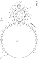
- number 1 indicates as a whole a labelling machine configured to apply labels 2 onto articles 3, such as bottles, receptacles, or the like, destined to contain a pourable product, in particular a pourable food product.
- labels 2 applied by labelling machine 1 are glued labels, i.e. strips of labelling material that are cut at predetermined lengths, from a web 4 of labelling material, and to which glue is applied.
- web 4 of labelling material is wound around one or more storage units, such as coils or reels (known per se and not shown).
- labelling machine 1 handles sleeve labels, i.e. tubular-like labels obtained from a web of heat-shrinkable labelling material.
- sleeve labels i.e. tubular-like labels obtained from a web of heat-shrinkable labelling material.
- such sleeve labels are applied onto the respective articles 3 with a certain predetermined backlash and then are heated up in an oven, so as to cause them to shrink and perfectly adhere onto the lateral surfaces of the same articles 3.
- Labelling machine 1 substantially comprises:
- labelling module 6 comprises:
- vacuum drum 8 sequentially receives, in use, labels 2 from transfer roller 9 at a receiving station R and retains labels 2 on an outer lateral surface 10 thereof.
- vacuum drum 8 has a substantially cylindrical-toroidal lobed configuration.
- lateral surface 10 has a substantially cylindrical shape and labels 2 are conveyed circumferentially from receiving station R to application station A, along an advancement direction, in this specific example a direction of rotation of vacuum drum 8.
- vacuum drum 8 is rotatably mounted around axis X onto a stationary distributor element 11 (schematically shown).
- distributor element 11 comprises first air passages (not shown) connected to a vacuum source (not shown).
- Vacuum drum 8 is, in turn, provided with second air passage (also not shown), which are configured to selectively communicate with the first air passages at certain angular positions assumed by vacuum drum 8, as this latter rotates about axis X, and end into a plurality of vacuum ports (known per se and not shown) formed through lateral surface 10.
- the vacuum ports are distributed onto one or more receiving portions 12 of lateral surface 10, each one of which angularly extends onto lateral surface 10 relatively to axis X and is configured to receive and retain one label 2 at a time, so that such label 2 is superimposed, in use, onto the corresponding receiving portion 12.
- each receiving portion 12 includes a pair of damping pads 13, in particular a leading pad and a trailing pad, angularly spaced from one another with respect to the direction of rotation of vacuum drum 8 about axis X and provided with the vacuum ports, and an intermediate section angularly comprised between pads 13.
- pads 13 are configured to retain respective end portions of each label 2 by means of vacuum-generated suction.
- leading pads are configured to retain the leading end portion of labels 2
- trailing pads are configured to retain the trailing end portion of labels 2.
- pads 13 define the end portions of each respective receiving portion 12.
- the angular distance between a leading pad and a trailing pad of each pair of pads 13 is substantially equal to the length of labels 2 to be handled by vacuum drum 8.
- labelling module 6 further comprises gluing means, in particular a gluing roller 14 arranged peripherally to vacuum drum 8, preferably substantially tangent to lateral surface 10, and configured to apply glue onto at least the end portions (leading end portion and trailing end portion) of each label 2 retained by receiving portion 12.
- gluing means in particular a gluing roller 14 arranged peripherally to vacuum drum 8, preferably substantially tangent to lateral surface 10, and configured to apply glue onto at least the end portions (leading end portion and trailing end portion) of each label 2 retained by receiving portion 12.
- gluing roller 14 defines a gluing station G located downstream of receiving station R and upstream of application station A.
- Labelling machine 1 further comprises first detection means, in this specific embodiment a first optical sensor 15 arranged peripherally with respect to vacuum drum 8 in a position downstream of application station A and upstream of receiving station R and configured to detect the labels 2 which, due to non-nominal operating conditions, are still retained by the corresponding receiving portions 12 downstream of application station A. Furthermore, first sensor 15 is configured to generate a presence signal correlated with the presence of labels 2 still retained by the corresponding receiving portions 12 downstream of application station A, and to send this latter signal to a control unit 16, which is in turn configured to receive the presence signal and, on the basis of such presence signal, to command labelling machine 1 to stop.
- first detection means in this specific embodiment a first optical sensor 15 arranged peripherally with respect to vacuum drum 8 in a position downstream of application station A and upstream of receiving station R and configured to detect the labels 2 which, due to non-nominal operating conditions, are still retained by the corresponding receiving portions 12 downstream of application station A.
- first sensor 15 is configured to generate a presence signal correlated with the presence of labels 2 still
- first sensor 15 detects the presence of such label 2, it generates the presence signal, which is then sent to control unit 16.
- control unit 16 commands the stop of labelling machine 1, in order to prevent waste of labelling material and unnecessary and undesired glue spreading onto vacuum drum 8.
- labelling machine 1 further comprises second detection means, in this specific embodiment a second optical sensor 17 arranged peripherally to vacuum drum 8 in a position downstream of receiving station R and upstream of application station A and configured to detect a positioning of label 2 onto lateral surface 10, in particular a positioning of label 2 relatively to receiving portion 12. Furthermore, second sensor 17 is configured to generate a positioning signal correlated with the positioning of this label 2 and, then, to send it to control unit 16.
- second detection means in this specific embodiment a second optical sensor 17 arranged peripherally to vacuum drum 8 in a position downstream of receiving station R and upstream of application station A and configured to detect a positioning of label 2 onto lateral surface 10, in particular a positioning of label 2 relatively to receiving portion 12.
- second sensor 17 is configured to generate a positioning signal correlated with the positioning of this label 2 and, then, to send it to control unit 16.
- second sensor 17 retrieves, in use, information about the angular positioning of label 2, with respect to axis X, relatively to receiving portion 12.
- second sensor 17 retrieves, in use, information about the angular positioning of label 2, with respect to axis X, relatively to pads 13.
- control unit 16 is further configured to compare the positioning signal sent by second sensor 17 with a predetermined nominal positioning, i.e. a nominal angular positioning, of label 2 onto lateral surface 10, in particular with a predetermined nominal angular positioning which label 2 should assume onto receiving portion 12, and between pads 13, in nominal operating conditions.
- a predetermined nominal positioning i.e. a nominal angular positioning
- second sensor 17 allows to perform a troubleshooting of the causes due to which label 2 could not be applied onto the respective article 3 at application station A. In fact, if second sensor 17 does not detect any non-nominal positioning of label 2 relatively to receiving portion 12 (and pads 13), the cutting performed by knife 7 and any vacuum ports fail and/or any other fail which can occur during the transfer of such label 2 from transfer roller 9 to vacuum drum 8 have to be excluded.
- second sensor 17 is capable of detect, in use, an angular offset, of a given angle W ( Figure 3 ) with respect to axis X, of label 2 with respect to receiving portion 12, i.e. a forward angular offset, of a given angle W, of label 2 with respect to the leading pad of receiving portion 12 or a backward angular offset, of a given angle W, of label 2 with respect to the trailing pad of the same receiving portion 12.
- control unit 16 is further configured to control an advancement, in particular a rotation, of said angle W, of vacuum drum 8 relatively to transfer roller 9, when the angular positioning detected by second sensor 17 differs, by the same angle W, from the nominal angular positioning.
- control unit 16 controls, in use, a backward rotation, of the same angle W, of vacuum drum 8 relatively to transfer drum 9; whereas, when second sensor 17 detects a backward angular offset, of a given angle W, of label 2 with respect to the trailing pad of receiving portion 12, control unit 16 controls, in use, a forward rotation, of the same angle W, of vacuum drum 8 relatively to transfer drum 9.
- labelling machine 1 can provide an automatic angular re-phasing of vacuum drum 8.
- second sensor 17 is conveniently arranged in a position downstream of receiving station R and upstream of gluing station G.
- second sensor 17 is configured to detect the angular positioning of label 2 onto lateral surface 10 relatively to receiving portion 12 (and pads 13) upstream the gluing station G.
- second sensor 17 retrieves, in use, information on the angular positioning of label 2 prior to the application of glue onto this latter by gluing roller 14, if second sensor 17 does not detect any non-nominal positioning of label 2 relatively to receiving portion 12 and pads 13, the gluing operation performed by gluing roller 14 could, with reasonable probability, be the cause due to which label 2 has not been applied onto the relative article 3 at application station A.
- control unit 16 is configured to control a movement of gluing roller 14 away from lateral surface 10, and therefore away from axis X and vacuum drum 18, when the angular positioning detected by second sensor 17 differs from the nominal angular positioning.
- control unit 16 is configured to control the rotation of vacuum drum 8 relatively to transfer drum 9 after a given number (more than one) of subsequent labels 2 are detected by second sensor 17 to be forwardly or backwardly protruding from the corresponding receiving portions 12, i.e. when a constant angular offset, that is a constant angular positioning error of labels 2 with respect to the corresponding receiving portions 12, is detected.
- control unit 16 will control a backward rotation, of the same angle W, of vacuum drum 8 relatively to transfer drum 9, so as to adjust the angular phasing of these latter.
- labelling machine 1 The operation of labelling machine 1 is described hereinafter with reference to a single label 2 to be retained by one respective receiving portion 12 and to be applied on a corresponding article 3 advanced by carousel 5, and starting from a condition in which such label 2 is transferred from transfer roller 9 to vacuum drum 8 at receiving station R.
- label 2 is received onto lateral surface 10 and retained by receiving portion 12, in particular retained by the relative pair of pads 13.
- second sensor 17 detects the angular positioning of label 2, generates a positioning signal correlated with the detection and send this latter signal to control unit 16.
- control unit 16 If control unit 16 detects any difference between the detected angular positioning and the nominal angular positioning, i.e. a forward or a backward angular offset, of a given angle W, it controls gluing roller 14 to move away from lateral surface 10 and also controls a backward or a forward rotation, of the same angle W, of vacuum drum 8 relatively to transfer drum 9, so that vacuum drum 8 can be re-phased relatively to transfer drum 9.
- the nominal angular positioning i.e. a forward or a backward angular offset
- first sensor 15 detects its presence, accordingly generates a presence signal and send this latter to control unit 16.
- control unit 16 commands a stop of labelling machine 1, preferably before label 2 reaches again receiving station R.
- labelling machine 1 is not stopped.
- control unit 16 will control a backward/forward rotation, of the same angle W, of vacuum drum 8 relatively to transfer drum 9, so as to adjust the angular phasing of these latter.
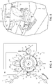
- Number 1' in Figure 4 indicates as a whole a labelling machine according to a second preferred embodiment of the present invention.
- labelling machine 1' is similar to labelling machine 1, only the differences with respect to this latter will be described, using the same numerals for similar or equivalent parts.
- labelling machine 1' further comprises:
- third sensor 19' is configured to generate the further presence signal whenever it detects one label 2 which remains still retained by the respective receiving portion 12, despite having passed application station A, and before they reach first sensor 15.
- control unit 16 which is configured to correspondingly send a command signal to activation means 20'.
- activation means 20' When activation means 20' receive the command signal, they activate extractor 18', which suck in the label 2 which has been detected by third sensor 19'.
- This configuration allows to prevent a stop of labelling machine 1', since no presence of any label 2 is detected by first sensor 15 downstream of extractor 18'.
- second sensor 17 allows to retrieve information about the nominal or non-nominal positioning of labels 2 at a specific position of such labels 2 during their advancement from receiving station R towards application station A and, therefore, to use such information to perform a troubleshooting of the causes due to which labels 2 are not applied onto articles 3 at application station A in an easy, cost-effective and time-effective manner.
- control unit 16 is configured to control a movement of gluing roller 14 away from vacuum drum 8, based on the positioning information provided by second sensor 17, i.e. when labels 2 are non-nominally retained by vacuum drum 8, allows to avoid waste of glue and undesired spreading of glue over vacuum drum 8.
- second sensor 17 permits to perform an automatic correction of the phasing between vacuum drum 8 and transfer roller 9.
- third sensor 19' and extractor 18' avoid a stop of labelling machine 1' in the case a label 2 remains still retained onto vacuum drum 8 downstream of extractor 18.
- second sensor 17 could be configured to detect not only the angular positioning of labels 2 relatively to the corresponding receiving portions 12, but also an axial positioning of labels 2 relatively to the same receiving portions 12.
- control unit 16 would be configured to compare such axial positioning with a predetermined nominal axial positioning of labels 2 relatively to receiving portions 12.
- second sensor 17 could detect a combination of such angular and axial positioning.
- the transfer element could be defined by a linear conveyor or a roto-translational conveyor configured to receive, retain and convey each single label 2, one after the other, from receiving station R to application station A, during nominal operating conditions.
- the feeding element configured to feed the sequence of single labels 2 previously cut by knife 7 could be defined by a linear conveyor or a roto-translational conveyor.
- the positioning error of labels 2 relatively to their corresponding receiving portions 12 would be defined by a linear quantity, i.e. a linear offset of linear length W.
Landscapes
- Labeling Devices (AREA)
Claims (19)
- Machine d'étiquetage (1, 1') pour appliquer des étiquettes (2) sur des articles (3) destinés à contenir un produit versable ; ladite machine d'étiquetage (1, 1') comprenant :un transporteur (5) configuré pour faire avancer une pluralité desdits articles (3) suivant une voie de transfert (P) ; etun élément de transfert (8), agencé en périphérie dudit transporteur (5) et configuré pour recevoir une séquence d'étiquettes seules (2) l'une après l'autre au niveau d'un poste de réception (R), pour retenir lesdites étiquettes (2) sur une surface latérale (10) correspondante et pour transporter lesdites étiquettes (2), suivant une direction d'avance, vers un poste d'application (A), au niveau duquel lesdites étiquettes (2) sont, lors de l'utilisation, libérées de ladite surface latérale (10) et sont, lors de l'utilisation, fournies audit transporteur (5) pour être appliquées sur lesdits articles (3) ;des troisièmes moyens de détection (19') agencés à une position en aval dudit poste d'application (A) ;des moyens d'extraction (18') pour lesdites étiquettes (2), agencés en périphérie dudit élément de transfert (8), à une position fonctionnelle en aval desdits troisièmes moyens de détection (19) ;caractérisée en ce qu'elle comprend des deuxièmes moyens de détection (17) agencés à une position en aval dudit poste de réception (R) et en amont dudit poste d'application (A), par rapport à ladite direction d'avance, et configurés pour détecter un positionnement de chaque étiquette (2) sur ladite surface latérale (10) et pour générer un signal de positionnement corrélé avec ledit positionnement de chacune desdites étiquettes (2) ;ladite machine d'étiquetage (1, 1') comprenant en outre des premiers moyens de détection (15), agencés en périphérie dudit élément de transfert (8) à une position en aval du poste d'application (A) et en amont dudit poste de réception (R), par rapport à ladite direction d'avance, et configurés pour détecter les étiquettes seules (2) encore retenues, lors de l'utilisation, par ladite surface latérale (10) en aval dudit poste d'application (A) et pour générer un signal de présence corrélé avec la présence desdites étiquettes (2) encore retenues, lors de l'utilisation, par ladite surface latérale (10) en aval dudit poste d'application (A) ;les troisièmes moyens de détection (19') étant agencés en amont desdits premiers moyens de détection (15) et configurés pour générer un autre signal de présence quand une étiquette (2) est présente sur ladite surface latérale (10) en aval dudit poste d'application (A) et en amont desdits premiers moyens de détection (15) ;les moyens d'extraction (18') étant agencés à une position fonctionnelle en amont desdits premiers moyens de détection (15) et définissant un poste de rejet (D') pour lesdites étiquettes (2) ; etladite machine d'étiquetage (1, 1') comprenant en outre des moyens d'activation (20') configurés pour activer lesdits moyens d'extraction (18') en réponse audit autre signal de présence.
- Machine d'étiquetage selon la revendication 1, comprenant en outre une unité de contrôle (16) configurée pour recevoir ledit signal de positionnement et pour comparer ledit positionnement de ladite étiquette (2) sur ladite surface latérale (10) à un positionnement nominal prédéterminé de ladite étiquette (2) sur ladite surface latérale (10).
- Machine d'étiquetage selon la revendication 2, dans laquelle ladite surface latérale (10) comprend au moins une partie de réception (12) s'étendant sur ladite surface latérale (10), avançant, lors de l'utilisation, suivant ladite direction d'avance et configurée pour recevoir une étiquette (2) à la fois au niveau dudit poste de réception (R) ;
lesdits deuxièmes moyens de détection (17) étant configurés pour détecter ledit positionnement de ladite étiquette (2) sur ladite surface latérale (10) par rapport à ladite partie de réception (12). - Machine d'étiquetage selon la revendication 3, dans laquelle ledit élément de transfert (8) comprend au moins une paire de patins successifs (13) espacés l'un de l'autre suivant ladite surface latérale (10) et définissant des parties extrêmes respectives de ladite partie de réception (12) ; lesdits patins (13) étant configurés pour retenir des parties extrêmes respectives de ladite étiquette (2) ;
lesdits deuxièmes moyens de détection (17) étant configurés pour détecter ledit positionnement de ladite étiquette (2) sur ladite surface latérale (10) par rapport auxdits patins (13). - Machine d'étiquetage selon la revendication 3 ou 4, dans laquelle ladite unité de contrôle (16) est configurée pour comparer ledit positionnement de ladite étiquette (2) sur ladite surface latérale (10) par rapport à ladite partie de réception (12) à un positionnement nominal prédéterminé de ladite étiquette (2) sur ladite surface latérale (10) par rapport à ladite partie de réception (12).
- Machine d'étiquetage selon la revendication 5, comprenant en outre des moyens de collage (14) agencés en périphérie par rapport audit élément de transfert (8) et définissant un poste de collage (G) situé en aval dudit poste de réception (R) et en amont dudit poste d'application (A), par rapport à ladite direction d'avance ; lesdits moyens de collage (14) étant configurés pour appliquer de la colle sur au moins une partie de ladite étiquette (2) ;
lesdits deuxièmes moyens de détection (17) étant agencés en amont dudit poste de collage (G) et étant configurés pour détecter ledit positionnement de ladite étiquette (2) sur ladite surface latérale (10) par rapport à ladite partie de réception (12) quand ladite étiquette (2) est en amont dudit poste de collage (G). - Machine d'étiquetage selon la revendication 6, dans laquelle lesdits moyens de collage (14) sont agencés à une position sensiblement tangente à ladite surface latérale (10) ;
et dans laquelle ladite unité de contrôle (16) est configurée pour contrôler un déplacement desdits moyens de collage (14) à l'opposé de ladite surface latérale (10) quand ledit positionnement détecté par lesdits deuxièmes moyens de détection (17) diffère, lors de l'utilisation, dudit positionnement nominal. - Machine d'étiquetage selon l'une quelconque des revendications 5 à 7, comprenant en outre un élément d'alimentation (9) agencé en périphérie dudit élément de transfert (8) et configuré pour alimenter ledit élément de transfert (8) avec ladite étiquette (2) au niveau dudit poste de réception (R) ;
ladite unité de contrôle (16) étant configurée pour contrôler une avance, d'une quantité donnée (W), dudit élément de transfert (8) par rapport audit élément d'alimentation (9), quand ledit positionnement détecté par lesdits deuxièmes moyens de détection (17) pour au moins une étiquette (2) diffère, lors de l'utilisation, dudit positionnement nominal de ladite quantité donnée (W). - Machine d'étiquetage selon la revendication 8, dans laquelle lesdits deuxièmes moyens de détection (17) sont configurés pour détecter un décalage, de ladite quantité donnée, (W), de ladite étiquette (2) par rapport à ladite partie de réception (12).
- Machine d'étiquetage selon la revendication 9, dans laquelle ladite unité de contrôle (16) est configurée pour contrôler une avance vers l'arrière, de ladite quantité donnée (W), dudit élément de transfert (8) par rapport audit élément d'alimentation (9), quand lesdits deuxièmes moyens de détection (17) détectent un décalage avant, de la même quantité donnée (W), de ladite étiquette (2) par rapport à ladite partie de réception (12), par rapport à ladite direction d'avance ;
et dans laquelle ladite unité de contrôle (16) est configurée pour contrôler une avance vers l'avant, de ladite quantité donnée (W), dudit élément de transfert (8) par rapport audit élément d'alimentation (9), quand lesdits deuxièmes moyens de détection (17) détectent un décalage arrière, de la même quantité donnée (W), de ladite étiquette (2) par rapport à ladite partie de réception (12), par rapport à ladite direction d'avance. - Machine d'étiquetage selon l'une quelconque des revendications précédentes, dans laquelle ledit élément de transfert comprend un tambour de transfert rotatif (8), rotatif autour d'un premier axe (X) ;
et dans laquelle ledit positionnement desdites étiquettes (2) détectées par lesdits deuxièmes moyens de détection (17) est un positionnement angulaire desdites étiquettes (2), par rapport audit premier axe (X), sur ladite surface latérale (10), et ledit positionnement nominal prédéterminé est un positionnement nominal angulaire prédéterminé. - Machine d'étiquetage selon la revendication 11 lorsqu'elle est dépendante de la revendication 9, dans laquelle ledit élément d'alimentation comprend un cylindre de transfert rotatif (9), rotatif autour d'un second axe (Y) parallèle audit premier axe (X) ;
dans laquelle ledit décalage est un décalage angulaire de ladite étiquette (2) par rapport à ladite partie de réception (12), par rapport audit premier axe (X) ;
dans laquelle ladite quantité donnée (W) est un angle donné ;
et dans laquelle ladite unité de contrôle (W) est configurée pour contrôler une rotation dudit angle donné (W) dudit tambour de transfert (8) par rapport audit cylindre de transfert (9), quand ledit positionnement angulaire détecté par lesdits deuxièmes moyens de détection (17) pour au moins une étiquette (2) diffère, lors de l'utilisation, dudit positionnement angulaire nominal dudit angle donné (W). - Procédé d'étiquetage d'articles (3) destinés à contenir un produit versable ; le procédé comprenant les étapes consistant à :faire avancer une pluralité d'articles (3) suivant une voie de transfert (P) ;transporter une succession d'étiquettes seules (2) l'une après l'autre depuis un poste de réception (R) vers un poste d'application (A), au niveau duquel lesdites étiquettes (2) sont respectivement appliquées sur lesdits articles (3) ;effectuer une autre détection des étiquettes (2) qui sont présentes en aval dudit poste d'application (A) ;générer un autre signal de présence quand des étiquettes (2) sont détectées pendant l'étape d'autre détection des étiquettes (2) ;extraire les étiquettes (2) détectées pendant l'étape d'autre détection des étiquettes (2) en réponse audit autre signal de présence ;caractérisé en ce qu'il comprend en outre les étapes consistant à :détecter un positionnement de chaque étiquette (2) en aval dudit poste de réception (R) et en amont dudit poste d'application (A) ; etgénérer un signal de positionnement corrélé avec ledit positionnement de ladite étiquette (2), détecté pendant l'étape de détection du positionnement ;détecter les étiquettes (2) qui font l'objet d'une autre avance depuis ledit poste d'application (A) vers ledit poste de réception (R) ; etgénérer un signal de contrôle quand des étiquettes (2) sont détectées pendant l'étape de détection des étiquettes (2) ;l'étape d'autre détection étant antérieure à l'étape de détection des étiquettes (2).
- Procédé selon la revendication 13, comprenant en outre l'étape consistant à :
comparer ledit positionnement détecté pendant l'étape de détection du positionnement à un positionnement nominal prédéterminé de ladite étiquette (2) en aval dudit poste de réception (R) et en amont dudit poste d'application (A). - Procédé selon la revendication 14, comprenant en outre l'étape consistant à :fournir des moyens de collage (14) agencés au niveau d'un poste de collage (G) situé en aval dudit poste de réception (R) et en amont dudit poste d'application (A) et configurés pour appliquer de la colle sur au moins une partie de chaque étiquette (2) ;l'étape consistant à détecter le positionnement étant réalisée après que les étiquettes (2) sont passées par ledit poste de réception (R) et avant que les étiquettes (2) n'aient atteint ledit poste de collage (G).
- Procédé selon la revendication 15, comprenant en outre l'étape consistant à :exclure n'importe quelle cause survenant en amont dudit poste de collage (G), en raison de laquelle un signal de contrôle est généré pendant l'étape de génération d'un signal de contrôle si, pendant l'étape de comparaison, ledit positionnement détecté pendant l'étape de détection du positionnement coïncide avec ledit positionnement nominal.
- Procédé selon la revendication 15 ou 16, comprenant en outre les étapes consistant à :transporter lesdites étiquettes (2) dudit poste de réception (R) audit poste d'application (A) suivant une direction d'avance ; etcontrôler lesdits moyens de collage (14) pour qu'ils se déplacent à l'opposé de ladite direction d'avance, quand ledit positionnement détecté pendant l'étape de détection du positionnement diffère dudit positionnement nominal.
- Procédé selon l'une quelconque des revendications 14 à 17, comprenant en outre les étapes consistant à :fournir un élément de transfert (8) configuré pour recevoir lesdites étiquettes (2) au niveau dudit poste de réception (R) et pour transporter lesdites étiquettes (2) au niveau dudit poste d'application (A) ; etfournir au moins une partie de réception (12) s'étendant sur ledit élément de transfert (8) et configuré pour recevoir au moins une étiquette (2) à la fois au niveau dudit poste de réception (R) ;le procédé comprenant en outre les étapes consistant à :détecter ledit positionnement de ladite étiquette (2) sur ledit élément de transfert (8) par rapport à ladite partie de réception (12) ; etcomparer ledit positionnement audit positionnement nominal prédéterminé de ladite étiquette (2) sur ledit élément de transfert (8) par rapport à ladite partie de réception (12).
- Procédé selon la revendication 18, comprenant en outre les étapes consistant à :alimenter ledit élément de transfert (8) avec chaque étiquette (2) au moyen d'au moins un élément d'alimentation (9) situé au niveau dudit poste de réception (R) et agencé en périphérie dudit élément de transfert (8) ; etcontrôler une avance, d'une quantité donnée (W), dudit élément de transfert (8) par rapport audit élément d'alimentation (9), quand ledit positionnement détecté à l'étape de détection du positionnement diffère, de ladite quantité donnée (W), dudit positionnement nominal.
Priority Applications (4)
| Application Number | Priority Date | Filing Date | Title |
|---|---|---|---|
| EP18306416.1A EP3647212B1 (fr) | 2018-10-30 | 2018-10-30 | Machine d'étiquetage et procédé de manipulation d'un matériau de marquage en forme de bande dans un processus d'étiquetage automatique |
| US17/290,250 US11524810B2 (en) | 2018-10-30 | 2019-10-14 | Labelling machine and method for handling a web-like labelling material in an automated labelling process |
| PCT/EP2019/077718 WO2020088919A1 (fr) | 2018-10-30 | 2019-10-14 | Machine à étiqueter et procédé de manipulation d'un matériau d'étiquetage en bande dans un processus d'étiquetage automatisé |
| CN201980071124.XA CN112930305B (zh) | 2018-10-30 | 2019-10-14 | 贴标机和在自动贴标过程中处理卷材状贴标材料的方法 |
Applications Claiming Priority (1)
| Application Number | Priority Date | Filing Date | Title |
|---|---|---|---|
| EP18306416.1A EP3647212B1 (fr) | 2018-10-30 | 2018-10-30 | Machine d'étiquetage et procédé de manipulation d'un matériau de marquage en forme de bande dans un processus d'étiquetage automatique |
Publications (2)
| Publication Number | Publication Date |
|---|---|
| EP3647212A1 EP3647212A1 (fr) | 2020-05-06 |
| EP3647212B1 true EP3647212B1 (fr) | 2021-03-17 |
Family
ID=64267750
Family Applications (1)
| Application Number | Title | Priority Date | Filing Date |
|---|---|---|---|
| EP18306416.1A Not-in-force EP3647212B1 (fr) | 2018-10-30 | 2018-10-30 | Machine d'étiquetage et procédé de manipulation d'un matériau de marquage en forme de bande dans un processus d'étiquetage automatique |
Country Status (4)
| Country | Link |
|---|---|
| US (1) | US11524810B2 (fr) |
| EP (1) | EP3647212B1 (fr) |
| CN (1) | CN112930305B (fr) |
| WO (1) | WO2020088919A1 (fr) |
Families Citing this family (3)
| Publication number | Priority date | Publication date | Assignee | Title |
|---|---|---|---|---|
| EP4206082A1 (fr) * | 2021-12-31 | 2023-07-05 | Bizerba SE & Co. KG | Étiqueteuse |
| CA3242892A1 (fr) * | 2022-02-21 | 2023-08-24 | P.E. Labellers S.P.A. | Machine d'etiquetage dotee de moyens de detection de presence ou d'absence d'etiquettes sur un tambour de travail |
| CN115285484B (zh) * | 2022-08-25 | 2023-12-12 | 中建材创新科技研究院有限公司 | 一种石膏板防伪芯片安装装置 |
Family Cites Families (8)
| Publication number | Priority date | Publication date | Assignee | Title |
|---|---|---|---|---|
| JPH0777896B2 (ja) * | 1987-08-11 | 1995-08-23 | ニュージャージー・マシーン・インコーポレイテツド | ラベル貼着装置及び方法 |
| JP3778532B2 (ja) * | 1997-04-10 | 2006-05-24 | 富士写真フイルム株式会社 | ラベル貼付方法及び装置 |
| CN101519141A (zh) * | 2008-02-18 | 2009-09-02 | 诺信公司 | 用于贴标签的设备和方法 |
| WO2012001831A1 (fr) * | 2010-06-28 | 2012-01-05 | 株式会社岩田レーベル | Dispositif de collage d'étiquettes d'identification |
| EP2832652B1 (fr) * | 2013-08-02 | 2017-04-26 | Sidel S.p.a. Con Socio Unico | Procédé de manipulation d'un matériau de marquage en forme de toile dans un processus d'étiquetage automatique, tambour sous vide de machine d'étiquetage et machine d'étiquetage |
| DE102014226937A1 (de) * | 2014-12-23 | 2016-06-23 | Krones Ag | Vorrichtung und Verfahren zum Etikettieren mit Etiketten mit aktivierbarem Kleber |
| EP3153419B1 (fr) * | 2015-10-05 | 2018-06-06 | Sidel Participations | Procédé et appareil de manipulation de récipients |
| CN209275063U (zh) * | 2017-09-06 | 2019-08-20 | 西得乐股份公司 | 贴标机 |
-
2018
- 2018-10-30 EP EP18306416.1A patent/EP3647212B1/fr not_active Not-in-force
-
2019
- 2019-10-14 US US17/290,250 patent/US11524810B2/en active Active
- 2019-10-14 CN CN201980071124.XA patent/CN112930305B/zh not_active Expired - Fee Related
- 2019-10-14 WO PCT/EP2019/077718 patent/WO2020088919A1/fr not_active Ceased
Also Published As
| Publication number | Publication date |
|---|---|
| CN112930305A (zh) | 2021-06-08 |
| EP3647212A1 (fr) | 2020-05-06 |
| WO2020088919A1 (fr) | 2020-05-07 |
| US11524810B2 (en) | 2022-12-13 |
| US20220017253A1 (en) | 2022-01-20 |
| CN112930305B (zh) | 2023-06-06 |
Similar Documents
| Publication | Publication Date | Title |
|---|---|---|
| KR102486369B1 (ko) | 용기에 라벨을 부착하기 위한 기계 및 방법 | |
| US11186401B2 (en) | Labelling machine configured to apply labels onto articles for containing a pourable product | |
| US11524810B2 (en) | Labelling machine and method for handling a web-like labelling material in an automated labelling process | |
| CN101511682B (zh) | 贴标签系统 | |
| JPH0285136A (ja) | 連続式感圧ラベル貼着装置及び方法 | |
| CN106573743A (zh) | 用于操纵卷绕在卷盘上的扁平材料和/或薄膜材料的方法和设备 | |
| CN212922305U (zh) | 贴标单元和用于贴标单元的自动调节系统 | |
| US11981043B2 (en) | Cutting device for cutting labels from a web of labelling material | |
| EP4615761A1 (fr) | Système d'alimentation en bande pour un module d'étiquetage pour préparer l'opération d'épissage | |
| EP3453660B1 (fr) | Procédé d'épissage de bandes | |
| US20230137654A1 (en) | Machine and method for labeling containers | |
| EP3822186B1 (fr) | Dispositif et procédé pour l'application de différent types ou formats d'étiquettes sur des articles | |
| WO2020114766A1 (fr) | Machine à étiqueter, procédé de manipulation d'un matériau d'étiquetage de type bande dans un processus d'étiquetage automatisé, et étiquette | |
| EP2367726B1 (fr) | Machine pour étiqueter au moyen d'étiquettes préencollées imprimées sur un ruban | |
| EP4310038A1 (fr) | Machine d'étiquetage pour étiqueter des récipients conçus pour contenir un produit versable et procédé pour raccorder deux toiles de matériau de d'étiquetage | |
| EP3760551A1 (fr) | Procédé pour appliquer des étiquettes sur des articles conçus pour contenir un produit versable | |
| WO2025103728A1 (fr) | Dispositif de support de bobine pour configuration d'empilement double | |
| WO2025036797A1 (fr) | Machine d'étiquetage configurée pour étiqueter des récipients au moyen d'étiquettes partielles par application coulissante | |
| WO2024146698A1 (fr) | Étiqueteuse à capacité d'amélioration de qualité automatique basée sur une détection visuelle | |
| EP4520674A1 (fr) | Tambour de transfert d'étiquettes avec des dispositifs de tampon monobloc pour étiqueter des récipients au moyen d'étiquettes partielles | |
| CN119486941A (zh) | 设有传感器设备的恢复模式和验证模式的标签进给系统 | |
| EP3988462A1 (fr) | Machine d'étiquetage et procédé pour appliquer des étiquettes sur des articles conçus pour contenir un produit versable | |
| WO2024032993A1 (fr) | Module d'étiquetage avec système de correction | |
| CA3044758C (fr) | Machine et procede d'etiquetage de contenants | |
| WO2023208606A1 (fr) | Système d'alimentation pour alimenter en bande de matériau d'étiquetage une machine d'étiquetage et procédé d'étiquetage associé |
Legal Events
| Date | Code | Title | Description |
|---|---|---|---|
| PUAI | Public reference made under article 153(3) epc to a published international application that has entered the european phase |
Free format text: ORIGINAL CODE: 0009012 |
|
| STAA | Information on the status of an ep patent application or granted ep patent |
Free format text: STATUS: THE APPLICATION HAS BEEN PUBLISHED |
|
| AK | Designated contracting states |
Kind code of ref document: A1 Designated state(s): AL AT BE BG CH CY CZ DE DK EE ES FI FR GB GR HR HU IE IS IT LI LT LU LV MC MK MT NL NO PL PT RO RS SE SI SK SM TR |
|
| AX | Request for extension of the european patent |
Extension state: BA ME |
|
| STAA | Information on the status of an ep patent application or granted ep patent |
Free format text: STATUS: REQUEST FOR EXAMINATION WAS MADE |
|
| 17P | Request for examination filed |
Effective date: 20200814 |
|
| RBV | Designated contracting states (corrected) |
Designated state(s): AL AT BE BG CH CY CZ DE DK EE ES FI FR GB GR HR HU IE IS IT LI LT LU LV MC MK MT NL NO PL PT RO RS SE SI SK SM TR |
|
| GRAP | Despatch of communication of intention to grant a patent |
Free format text: ORIGINAL CODE: EPIDOSNIGR1 |
|
| STAA | Information on the status of an ep patent application or granted ep patent |
Free format text: STATUS: GRANT OF PATENT IS INTENDED |
|
| RIC1 | Information provided on ipc code assigned before grant |
Ipc: B65C 9/40 20060101ALI20201130BHEP Ipc: B65C 9/42 20060101ALI20201130BHEP Ipc: B65C 9/18 20060101AFI20201130BHEP |
|
| INTG | Intention to grant announced |
Effective date: 20201223 |
|
| GRAS | Grant fee paid |
Free format text: ORIGINAL CODE: EPIDOSNIGR3 |
|
| GRAA | (expected) grant |
Free format text: ORIGINAL CODE: 0009210 |
|
| STAA | Information on the status of an ep patent application or granted ep patent |
Free format text: STATUS: THE PATENT HAS BEEN GRANTED |
|
| AK | Designated contracting states |
Kind code of ref document: B1 Designated state(s): AL AT BE BG CH CY CZ DE DK EE ES FI FR GB GR HR HU IE IS IT LI LT LU LV MC MK MT NL NO PL PT RO RS SE SI SK SM TR |
|
| REG | Reference to a national code |
Ref country code: GB Ref legal event code: FG4D |
|
| REG | Reference to a national code |
Ref country code: CH Ref legal event code: EP |
|
| REG | Reference to a national code |
Ref country code: DE Ref legal event code: R096 Ref document number: 602018014027 Country of ref document: DE |
|
| REG | Reference to a national code |
Ref country code: IE Ref legal event code: FG4D |
|
| REG | Reference to a national code |
Ref country code: AT Ref legal event code: REF Ref document number: 1372033 Country of ref document: AT Kind code of ref document: T Effective date: 20210415 |
|
| REG | Reference to a national code |
Ref country code: LT Ref legal event code: MG9D |
|
| PG25 | Lapsed in a contracting state [announced via postgrant information from national office to epo] |
Ref country code: BG Free format text: LAPSE BECAUSE OF FAILURE TO SUBMIT A TRANSLATION OF THE DESCRIPTION OR TO PAY THE FEE WITHIN THE PRESCRIBED TIME-LIMIT Effective date: 20210617 Ref country code: GR Free format text: LAPSE BECAUSE OF FAILURE TO SUBMIT A TRANSLATION OF THE DESCRIPTION OR TO PAY THE FEE WITHIN THE PRESCRIBED TIME-LIMIT Effective date: 20210618 Ref country code: HR Free format text: LAPSE BECAUSE OF FAILURE TO SUBMIT A TRANSLATION OF THE DESCRIPTION OR TO PAY THE FEE WITHIN THE PRESCRIBED TIME-LIMIT Effective date: 20210317 Ref country code: FI Free format text: LAPSE BECAUSE OF FAILURE TO SUBMIT A TRANSLATION OF THE DESCRIPTION OR TO PAY THE FEE WITHIN THE PRESCRIBED TIME-LIMIT Effective date: 20210317 Ref country code: NO Free format text: LAPSE BECAUSE OF FAILURE TO SUBMIT A TRANSLATION OF THE DESCRIPTION OR TO PAY THE FEE WITHIN THE PRESCRIBED TIME-LIMIT Effective date: 20210617 |
|
| REG | Reference to a national code |
Ref country code: AT Ref legal event code: MK05 Ref document number: 1372033 Country of ref document: AT Kind code of ref document: T Effective date: 20210317 |
|
| REG | Reference to a national code |
Ref country code: NL Ref legal event code: MP Effective date: 20210317 |
|
| PG25 | Lapsed in a contracting state [announced via postgrant information from national office to epo] |
Ref country code: SE Free format text: LAPSE BECAUSE OF FAILURE TO SUBMIT A TRANSLATION OF THE DESCRIPTION OR TO PAY THE FEE WITHIN THE PRESCRIBED TIME-LIMIT Effective date: 20210317 Ref country code: RS Free format text: LAPSE BECAUSE OF FAILURE TO SUBMIT A TRANSLATION OF THE DESCRIPTION OR TO PAY THE FEE WITHIN THE PRESCRIBED TIME-LIMIT Effective date: 20210317 Ref country code: LV Free format text: LAPSE BECAUSE OF FAILURE TO SUBMIT A TRANSLATION OF THE DESCRIPTION OR TO PAY THE FEE WITHIN THE PRESCRIBED TIME-LIMIT Effective date: 20210317 |
|
| PG25 | Lapsed in a contracting state [announced via postgrant information from national office to epo] |
Ref country code: NL Free format text: LAPSE BECAUSE OF FAILURE TO SUBMIT A TRANSLATION OF THE DESCRIPTION OR TO PAY THE FEE WITHIN THE PRESCRIBED TIME-LIMIT Effective date: 20210317 |
|
| PG25 | Lapsed in a contracting state [announced via postgrant information from national office to epo] |
Ref country code: LT Free format text: LAPSE BECAUSE OF FAILURE TO SUBMIT A TRANSLATION OF THE DESCRIPTION OR TO PAY THE FEE WITHIN THE PRESCRIBED TIME-LIMIT Effective date: 20210317 Ref country code: EE Free format text: LAPSE BECAUSE OF FAILURE TO SUBMIT A TRANSLATION OF THE DESCRIPTION OR TO PAY THE FEE WITHIN THE PRESCRIBED TIME-LIMIT Effective date: 20210317 Ref country code: CZ Free format text: LAPSE BECAUSE OF FAILURE TO SUBMIT A TRANSLATION OF THE DESCRIPTION OR TO PAY THE FEE WITHIN THE PRESCRIBED TIME-LIMIT Effective date: 20210317 Ref country code: SM Free format text: LAPSE BECAUSE OF FAILURE TO SUBMIT A TRANSLATION OF THE DESCRIPTION OR TO PAY THE FEE WITHIN THE PRESCRIBED TIME-LIMIT Effective date: 20210317 Ref country code: AT Free format text: LAPSE BECAUSE OF FAILURE TO SUBMIT A TRANSLATION OF THE DESCRIPTION OR TO PAY THE FEE WITHIN THE PRESCRIBED TIME-LIMIT Effective date: 20210317 |
|
| PG25 | Lapsed in a contracting state [announced via postgrant information from national office to epo] |
Ref country code: IS Free format text: LAPSE BECAUSE OF FAILURE TO SUBMIT A TRANSLATION OF THE DESCRIPTION OR TO PAY THE FEE WITHIN THE PRESCRIBED TIME-LIMIT Effective date: 20210717 Ref country code: PT Free format text: LAPSE BECAUSE OF FAILURE TO SUBMIT A TRANSLATION OF THE DESCRIPTION OR TO PAY THE FEE WITHIN THE PRESCRIBED TIME-LIMIT Effective date: 20210719 Ref country code: PL Free format text: LAPSE BECAUSE OF FAILURE TO SUBMIT A TRANSLATION OF THE DESCRIPTION OR TO PAY THE FEE WITHIN THE PRESCRIBED TIME-LIMIT Effective date: 20210317 Ref country code: SK Free format text: LAPSE BECAUSE OF FAILURE TO SUBMIT A TRANSLATION OF THE DESCRIPTION OR TO PAY THE FEE WITHIN THE PRESCRIBED TIME-LIMIT Effective date: 20210317 Ref country code: RO Free format text: LAPSE BECAUSE OF FAILURE TO SUBMIT A TRANSLATION OF THE DESCRIPTION OR TO PAY THE FEE WITHIN THE PRESCRIBED TIME-LIMIT Effective date: 20210317 |
|
| REG | Reference to a national code |
Ref country code: DE Ref legal event code: R097 Ref document number: 602018014027 Country of ref document: DE |
|
| PLBE | No opposition filed within time limit |
Free format text: ORIGINAL CODE: 0009261 |
|
| STAA | Information on the status of an ep patent application or granted ep patent |
Free format text: STATUS: NO OPPOSITION FILED WITHIN TIME LIMIT |
|
| PG25 | Lapsed in a contracting state [announced via postgrant information from national office to epo] |
Ref country code: ES Free format text: LAPSE BECAUSE OF FAILURE TO SUBMIT A TRANSLATION OF THE DESCRIPTION OR TO PAY THE FEE WITHIN THE PRESCRIBED TIME-LIMIT Effective date: 20210317 Ref country code: AL Free format text: LAPSE BECAUSE OF FAILURE TO SUBMIT A TRANSLATION OF THE DESCRIPTION OR TO PAY THE FEE WITHIN THE PRESCRIBED TIME-LIMIT Effective date: 20210317 Ref country code: DK Free format text: LAPSE BECAUSE OF FAILURE TO SUBMIT A TRANSLATION OF THE DESCRIPTION OR TO PAY THE FEE WITHIN THE PRESCRIBED TIME-LIMIT Effective date: 20210317 |
|
| 26N | No opposition filed |
Effective date: 20211220 |
|
| REG | Reference to a national code |
Ref country code: CH Ref legal event code: PL |
|
| PG25 | Lapsed in a contracting state [announced via postgrant information from national office to epo] |
Ref country code: IS Free format text: LAPSE BECAUSE OF FAILURE TO SUBMIT A TRANSLATION OF THE DESCRIPTION OR TO PAY THE FEE WITHIN THE PRESCRIBED TIME-LIMIT Effective date: 20210717 |
|
| REG | Reference to a national code |
Ref country code: BE Ref legal event code: MM Effective date: 20211031 |
|
| PG25 | Lapsed in a contracting state [announced via postgrant information from national office to epo] |
Ref country code: MC Free format text: LAPSE BECAUSE OF FAILURE TO SUBMIT A TRANSLATION OF THE DESCRIPTION OR TO PAY THE FEE WITHIN THE PRESCRIBED TIME-LIMIT Effective date: 20210317 |
|
| PG25 | Lapsed in a contracting state [announced via postgrant information from national office to epo] |
Ref country code: LU Free format text: LAPSE BECAUSE OF NON-PAYMENT OF DUE FEES Effective date: 20211030 Ref country code: BE Free format text: LAPSE BECAUSE OF NON-PAYMENT OF DUE FEES Effective date: 20211031 |
|
| PG25 | Lapsed in a contracting state [announced via postgrant information from national office to epo] |
Ref country code: LI Free format text: LAPSE BECAUSE OF NON-PAYMENT OF DUE FEES Effective date: 20211031 Ref country code: CH Free format text: LAPSE BECAUSE OF NON-PAYMENT OF DUE FEES Effective date: 20211031 |
|
| PG25 | Lapsed in a contracting state [announced via postgrant information from national office to epo] |
Ref country code: IE Free format text: LAPSE BECAUSE OF NON-PAYMENT OF DUE FEES Effective date: 20211030 |
|
| P01 | Opt-out of the competence of the unified patent court (upc) registered |
Effective date: 20230306 |
|
| GBPC | Gb: european patent ceased through non-payment of renewal fee |
Effective date: 20221030 |
|
| PG25 | Lapsed in a contracting state [announced via postgrant information from national office to epo] |
Ref country code: CY Free format text: LAPSE BECAUSE OF FAILURE TO SUBMIT A TRANSLATION OF THE DESCRIPTION OR TO PAY THE FEE WITHIN THE PRESCRIBED TIME-LIMIT Effective date: 20210317 |
|
| PG25 | Lapsed in a contracting state [announced via postgrant information from national office to epo] |
Ref country code: HU Free format text: LAPSE BECAUSE OF FAILURE TO SUBMIT A TRANSLATION OF THE DESCRIPTION OR TO PAY THE FEE WITHIN THE PRESCRIBED TIME-LIMIT; INVALID AB INITIO Effective date: 20181030 |
|
| PG25 | Lapsed in a contracting state [announced via postgrant information from national office to epo] |
Ref country code: SI Free format text: LAPSE BECAUSE OF FAILURE TO SUBMIT A TRANSLATION OF THE DESCRIPTION OR TO PAY THE FEE WITHIN THE PRESCRIBED TIME-LIMIT Effective date: 20210317 |
|
| PG25 | Lapsed in a contracting state [announced via postgrant information from national office to epo] |
Ref country code: GB Free format text: LAPSE BECAUSE OF NON-PAYMENT OF DUE FEES Effective date: 20221030 |
|
| PGFP | Annual fee paid to national office [announced via postgrant information from national office to epo] |
Ref country code: IT Payment date: 20230920 Year of fee payment: 6 |
|
| PGFP | Annual fee paid to national office [announced via postgrant information from national office to epo] |
Ref country code: FR Payment date: 20230920 Year of fee payment: 6 |
|
| PGFP | Annual fee paid to national office [announced via postgrant information from national office to epo] |
Ref country code: DE Payment date: 20230920 Year of fee payment: 6 |
|
| PG25 | Lapsed in a contracting state [announced via postgrant information from national office to epo] |
Ref country code: MK Free format text: LAPSE BECAUSE OF FAILURE TO SUBMIT A TRANSLATION OF THE DESCRIPTION OR TO PAY THE FEE WITHIN THE PRESCRIBED TIME-LIMIT Effective date: 20210317 |
|
| PG25 | Lapsed in a contracting state [announced via postgrant information from national office to epo] |
Ref country code: TR Free format text: LAPSE BECAUSE OF FAILURE TO SUBMIT A TRANSLATION OF THE DESCRIPTION OR TO PAY THE FEE WITHIN THE PRESCRIBED TIME-LIMIT Effective date: 20210317 |
|
| PG25 | Lapsed in a contracting state [announced via postgrant information from national office to epo] |
Ref country code: MT Free format text: LAPSE BECAUSE OF FAILURE TO SUBMIT A TRANSLATION OF THE DESCRIPTION OR TO PAY THE FEE WITHIN THE PRESCRIBED TIME-LIMIT Effective date: 20210317 |
|
| REG | Reference to a national code |
Ref country code: DE Ref legal event code: R119 Ref document number: 602018014027 Country of ref document: DE |
|
| PG25 | Lapsed in a contracting state [announced via postgrant information from national office to epo] |
Ref country code: DE Free format text: LAPSE BECAUSE OF NON-PAYMENT OF DUE FEES Effective date: 20250501 |
|
| PG25 | Lapsed in a contracting state [announced via postgrant information from national office to epo] |
Ref country code: FR Free format text: LAPSE BECAUSE OF NON-PAYMENT OF DUE FEES Effective date: 20241031 |
|
| PG25 | Lapsed in a contracting state [announced via postgrant information from national office to epo] |
Ref country code: IT Free format text: LAPSE BECAUSE OF NON-PAYMENT OF DUE FEES Effective date: 20241030 |