EP3647214A1 - Récipient en résine synthétique - Google Patents
Récipient en résine synthétique Download PDFInfo
- Publication number
- EP3647214A1 EP3647214A1 EP18824423.0A EP18824423A EP3647214A1 EP 3647214 A1 EP3647214 A1 EP 3647214A1 EP 18824423 A EP18824423 A EP 18824423A EP 3647214 A1 EP3647214 A1 EP 3647214A1
- Authority
- EP
- European Patent Office
- Prior art keywords
- shoulder
- container
- protruding ribs
- pair
- synthetic resin
- Prior art date
- Legal status (The legal status is an assumption and is not a legal conclusion. Google has not performed a legal analysis and makes no representation as to the accuracy of the status listed.)
- Withdrawn
Links
- 229920003002 synthetic resin Polymers 0.000 title claims abstract description 30
- 239000000057 synthetic resin Substances 0.000 title claims abstract description 30
- 238000000071 blow moulding Methods 0.000 description 7
- 239000004743 Polypropylene Substances 0.000 description 4
- 229920000139 polyethylene terephthalate Polymers 0.000 description 4
- 239000005020 polyethylene terephthalate Substances 0.000 description 4
- -1 polypropylene Polymers 0.000 description 4
- 229920001155 polypropylene Polymers 0.000 description 4
- 230000000694 effects Effects 0.000 description 3
- 238000011038 discontinuous diafiltration by volume reduction Methods 0.000 description 2
- 238000010101 extrusion blow moulding Methods 0.000 description 2
- 235000013361 beverage Nutrition 0.000 description 1
- 239000002537 cosmetic Substances 0.000 description 1
- 230000003247 decreasing effect Effects 0.000 description 1
- 239000003599 detergent Substances 0.000 description 1
- 238000010586 diagram Methods 0.000 description 1
- 238000007599 discharging Methods 0.000 description 1
- 238000001125 extrusion Methods 0.000 description 1
- 239000012530 fluid Substances 0.000 description 1
- 238000001746 injection moulding Methods 0.000 description 1
- 239000007788 liquid Substances 0.000 description 1
- 230000002093 peripheral effect Effects 0.000 description 1
- 239000002994 raw material Substances 0.000 description 1
- 239000002453 shampoo Substances 0.000 description 1
- 239000000243 solution Substances 0.000 description 1
- 239000000126 substance Substances 0.000 description 1
- 230000008961 swelling Effects 0.000 description 1
- 229920001169 thermoplastic Polymers 0.000 description 1
- 239000004416 thermosoftening plastic Substances 0.000 description 1
Images



Classifications
-
- B—PERFORMING OPERATIONS; TRANSPORTING
- B65—CONVEYING; PACKING; STORING; HANDLING THIN OR FILAMENTARY MATERIAL
- B65D—CONTAINERS FOR STORAGE OR TRANSPORT OF ARTICLES OR MATERIALS, e.g. BAGS, BARRELS, BOTTLES, BOXES, CANS, CARTONS, CRATES, DRUMS, JARS, TANKS, HOPPERS, FORWARDING CONTAINERS; ACCESSORIES, CLOSURES, OR FITTINGS THEREFOR; PACKAGING ELEMENTS; PACKAGES
- B65D1/00—Rigid or semi-rigid containers having bodies formed in one piece, e.g. by casting metallic material, by moulding plastics, by blowing vitreous material, by throwing ceramic material, by moulding pulped fibrous material or by deep-drawing operations performed on sheet material
- B65D1/02—Bottles or similar containers with necks or like restricted apertures, designed for pouring contents
- B65D1/0223—Bottles or similar containers with necks or like restricted apertures, designed for pouring contents characterised by shape
- B65D1/0292—Foldable bottles
-
- B—PERFORMING OPERATIONS; TRANSPORTING
- B65—CONVEYING; PACKING; STORING; HANDLING THIN OR FILAMENTARY MATERIAL
- B65D—CONTAINERS FOR STORAGE OR TRANSPORT OF ARTICLES OR MATERIALS, e.g. BAGS, BARRELS, BOTTLES, BOXES, CANS, CARTONS, CRATES, DRUMS, JARS, TANKS, HOPPERS, FORWARDING CONTAINERS; ACCESSORIES, CLOSURES, OR FITTINGS THEREFOR; PACKAGING ELEMENTS; PACKAGES
- B65D1/00—Rigid or semi-rigid containers having bodies formed in one piece, e.g. by casting metallic material, by moulding plastics, by blowing vitreous material, by throwing ceramic material, by moulding pulped fibrous material or by deep-drawing operations performed on sheet material
- B65D1/02—Bottles or similar containers with necks or like restricted apertures, designed for pouring contents
- B65D1/0223—Bottles or similar containers with necks or like restricted apertures, designed for pouring contents characterised by shape
- B65D1/0261—Bottom construction
- B65D1/0276—Bottom construction having a continuous contact surface, e.g. Champagne-type bottom
-
- B—PERFORMING OPERATIONS; TRANSPORTING
- B65—CONVEYING; PACKING; STORING; HANDLING THIN OR FILAMENTARY MATERIAL
- B65D—CONTAINERS FOR STORAGE OR TRANSPORT OF ARTICLES OR MATERIALS, e.g. BAGS, BARRELS, BOTTLES, BOXES, CANS, CARTONS, CRATES, DRUMS, JARS, TANKS, HOPPERS, FORWARDING CONTAINERS; ACCESSORIES, CLOSURES, OR FITTINGS THEREFOR; PACKAGING ELEMENTS; PACKAGES
- B65D1/00—Rigid or semi-rigid containers having bodies formed in one piece, e.g. by casting metallic material, by moulding plastics, by blowing vitreous material, by throwing ceramic material, by moulding pulped fibrous material or by deep-drawing operations performed on sheet material
- B65D1/02—Bottles or similar containers with necks or like restricted apertures, designed for pouring contents
- B65D1/0207—Bottles or similar containers with necks or like restricted apertures, designed for pouring contents characterised by material, e.g. composition, physical features
-
- B—PERFORMING OPERATIONS; TRANSPORTING
- B65—CONVEYING; PACKING; STORING; HANDLING THIN OR FILAMENTARY MATERIAL
- B65D—CONTAINERS FOR STORAGE OR TRANSPORT OF ARTICLES OR MATERIALS, e.g. BAGS, BARRELS, BOTTLES, BOXES, CANS, CARTONS, CRATES, DRUMS, JARS, TANKS, HOPPERS, FORWARDING CONTAINERS; ACCESSORIES, CLOSURES, OR FITTINGS THEREFOR; PACKAGING ELEMENTS; PACKAGES
- B65D2501/00—Containers having bodies formed in one piece
- B65D2501/0009—Bottles or similar containers with necks or like restricted apertures designed for pouring contents
- B65D2501/0018—Ribs
- B65D2501/0027—Hollow longitudinal ribs
-
- B—PERFORMING OPERATIONS; TRANSPORTING
- B65—CONVEYING; PACKING; STORING; HANDLING THIN OR FILAMENTARY MATERIAL
- B65D—CONTAINERS FOR STORAGE OR TRANSPORT OF ARTICLES OR MATERIALS, e.g. BAGS, BARRELS, BOTTLES, BOXES, CANS, CARTONS, CRATES, DRUMS, JARS, TANKS, HOPPERS, FORWARDING CONTAINERS; ACCESSORIES, CLOSURES, OR FITTINGS THEREFOR; PACKAGING ELEMENTS; PACKAGES
- B65D2501/00—Containers having bodies formed in one piece
- B65D2501/0009—Bottles or similar containers with necks or like restricted apertures designed for pouring contents
- B65D2501/0081—Bottles of non-circular cross-section
Definitions
- the present disclosure relates to a synthetic resin container that has a mouth, a shoulder, a body and a bottom and is foldable.
- Synthetic resin containers representatives of which are polypropylene (PP) bottles and polyethylene terephthalate (PET) bottles, have been used as containers that contain a variety of contents such as beverages and toiletries including cosmetics, chemicals, detergents, shampoos or the like.
- PP polypropylene
- PET polyethylene terephthalate
- Such a container includes, for example, a cylindrical mouth, a shoulder continuous to the lower side of the mouth, a body continuous to the shoulder and a bottom that closes the lower end of the body, and can be formed by blow molding such as biaxial stretch blow molding in which a test tube shaped preform is used and extrusion blow molding in which a parison extruded into a tubular shape is used.
- Patent Literature 1 discloses a blow molding method in which a cylindrical parison is placed in a mold for blow molding and a pressurized fluid is supplied into the parison to mold the parison into a container having a predetermined shape conforming to a cavity of the mold.
- a container is proposed in which, after the contents are used up, the body of the container can be flattened and folded to reduce its volume when the container is discarded.
- a container is configured to be foldable in the above described manner, it is possible to reduce not only the volume of the container when it is discarded but also the residual volume of the contents in the case where the container is used in particular for the contents with a high viscosity.
- the disclosed synthetic resin container is a synthetic resin container configured to include a mouth, a shoulder, a body and a bottom and to form a space for accommodating contents, in which the shoulder is provided with a pair of protruding ribs that are disposed opposite to each other on the front side and the rear side across a central axis line of the container and are foldable when the shoulder is flattened; the pair of protruding ribs are respectively formed into a curved shape with a central portion projecting toward the mouth side in a front view or a rear view; and both ends of one of the pair of protruding ribs connect to both ends of another one of protruding ribs, respectively, at intermediate positions of the shoulder.
- the body has a flat shape with a width larger than a thickness.
- each of the protruding ribs is adjacent to a base end portion of the mouth.
- a pair of connecting portions where the both ends of one of the protruding ribs are connected with the both ends of the another one of the protruding ribs, respectively, are each provided with a triangular flat plane.
- a synthetic resin container having a shoulder capable of being folded easily can be provided.
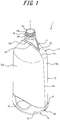
- a synthetic resin container 1 (hereinafter referred to also as a "container 1") according to an embodiment of the present disclosure illustrated in FIGS. 1 to 5 has a tubular mouth 10, a shoulder 11 continuous to the lower end of the mouth 10 and expanding radially outward, a body 12 continuous to the outer peripheral edge of the shoulder 11 and extending downward, and a bottom 13 continuous to the lower end of the body 12.
- the shoulder 11 is continuous to the lower side of the mouth 10 through a bent portion or a curved portion, and is configured such that an angle thereof relative to a central axis line C of the container 1 is different from that of the mouth 10.
- the body 12 is continuous to the lower side of the shoulder 11 through the bent portion or the curved portion, and is configured such that an angle thereof relative to the central axis line C is different from that of the shoulder 11.
- Inside the container 1 is a space for accommodating contents.
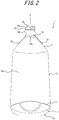
- FIG. 2 is a front view of the container 1 viewed from one side in the short axis direction of the flat body 12
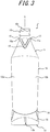
- FIG. 3 is a side view of the container 1 viewed from one side in the long axis direction of the body 12.
- the mouth 10 is formed into a cylindrical shape, and its outer periphery is provided with a male thread 10a to which a cap or a dispensing plug is mounted.
- a neck ring 10b is provided under the male thread 10a, and the container 1 can be transferred by supporting the lower side of the neck ring 10b with a transfer apparatus, for example.
- a top opening 10c of the mouth 10 is an outflow port for contents and can be closed by mounting a cap thereto.
- the shoulder 11 connects the mouth 10 and the body 12, and has a diameter gradually expanding downward from the mouth 10 side to the body 12 side. It is to be noted that, in this example, although the shoulder 11 is formed from a substantially flat inclined surface in which a contour line is linear in the front view (see FIG. 2 ) and the side view (see FIG. 3 ), this is not restrictive, and may be formed into a dome shape swelling outward from the container 1, for example.
- the shoulder 11 has a pair of protruding ribs 16 and 17 disposed opposite to each other on the front side and the rear side across the central axis line C. It is to be noted that, in this example, each central axis line of the mouth 10, the shoulder 11, the body 12 and the bottom 13 coincides with the central axis line C of the container 1.
- the protruding ribs 16 and 17 are formed such that they protrude from the outer surface of the shoulder 11 to the outside of the container, and recesses corresponding to the protruding ribs 16 and 17 are formed on the inner surface of the shoulder 11. Further, the protruding ribs 16 and 17 are each formed into a curved shape with central portions 16a and 17a each protruding toward the mouth 10 side (upper side).
- Both ends of one protruding rib 16 of the pair of protruding ribs 16 and 17 are connected to both ends of the other protruding rib 17, respectively, at each intermediate position of the shoulder 11.
- the "intermediate position of the shoulder 11" refers to a position in the region between the end (upper end) on the mouth 10 side and the end (lower end) on the body 12 side of the shoulder 11.
- connecting portions 18 connecting both ends of the protruding rib 16 and both ends of the protruding rib 17 are formed into a bent portion protruding downward in a side view.
- Such a pair of protruding ribs 16 and 17 become a starting point for folding a wall surface of the shoulder 11 when the shoulder 11 is flattened with the body 12 in the thickness direction. That is, the shoulder 11 can be easily folded along the protruding ribs 16 and 17.
- Respective central portions 16a and 17a of the pair of protruding ribs 16 and 17 are adjacent to the base end portion of the mouth 10.
- a portion of the shoulder 11 being adjacent to the base end portion of the mouth 10, that is, an upper end portion of the shoulder 11 tends to be formed thick and difficult to be deformed.
- the central portion 16a of the protruding rib 16, which is a starting point of folding is disposed on the upper end portion, which allows for easy deformation and prevents the shoulder 11 from being formed thick.
- the body 12 has a flat shape with a width (a length of the body 12 in the long axis direction) larger than a thickness (a length of the body 12 in the short axis direction). It is to be noted that, in a lateral cross-section of the body 12 perpendicular to the central axis line C, the short axis direction is defined as a thickness direction and the long axis direction perpendicular to the short axis direction is defined as a width direction.
- the shoulder 11 and the bottom 13 may include a portion that is not flat (a portion where the thickness and the width are the same), or the entire portion thereof may not be flat (a portion where the thickness and the width are the same).
- T represents the maximum thickness
- W represents the maximum width of the body 12.
- the body 12 has a front wall 12a and a rear wall 12b opposite to each other in the thickness direction across the central axis line C.
- Each boundary between the front wall 12a and the rear wall 12b is provided with a longitudinal folding line portion 12c that acts as a mountain crease when the body 12 is flattened. This enables the body 12 to be easily flattened in the thickness direction (short axis direction) such that the front wall 12a and the rear wall 12b are close to each other.
- each longitudinal folding line portion 11a continuous to each longitudinal folding line portion 12c is provided also to the shoulder 11, and the longitudinal folding line portion 11a acts as a mountain crease.
- the longitudinal folding line portion 11a is connected to the end of the protruding ribs 16 and 17, which allows the body 12 and the shoulder 11 to be more easily flattened in the thickness direction. It is to be noted that, in this example, when the shoulder 11 and the body 12 are flattened in the thickness direction, the longitudinal folding line portion 12c and the longitudinal folding line portion 11a are displaced, as mountain creases, outward in the width direction. However, this is not restrictive, and the container 1 may be configured to be folded such that the longitudinal folding line portion 12c and the longitudinal folding line portion 11a are folded inward in the width direction. It is to be noted that, in this example, although the longitudinal folding line portion 12c and the longitudinal folding line portion 11a are formed into a protruding rib shape, they may be formed into a recessed groove.
- the body 12 is provided with a lateral folding line portion 14 extending in the circumferential direction of the body 12.
- the lateral folding line portion 14 acts as a valley crease when the body 12 is flattened in the thickness direction, and can be a starting point for folding. It is to be noted that the lateral folding line portion 14 can act also as a mountain crease. It is to be noted that, in this example, although the lateral folding line portion 14 is formed into a recessed groove shape, it may be formed into a protruding rib shape.
- the lateral folding line portion 14 is provided at the lower half portion (half portion on the bottom 13 side) of the body 12.
- the same lateral folding line portion 14 is provided to the front wall 12a and the rear wall 12b.
- a pair of lateral folding line portions 14 disposed opposite to each other in the thickness direction of the body 12 are connected to each other on the boundary between the front wall 12a and the rear wall 12b (longitudinal folding line portion 12c).
- the lateral folding line portion 14 is not an essential component.
- the lateral folding line portion 14 may be provided on the upper half portion of the body 12, or a plurality of lateral folding line portions 14 may be provided at intervals in the height direction of the container 1.
- the lateral folding line portion 14 may be provided such that it extends only over a part in the circumferential direction of the body 12.
- the lateral folding line portion 14 may be provided to only either the front wall 12a or the rear wall 12b. It is to be noted that, in the side view illustrated in FIG. 3 , the lateral folding line portion 14 forms a recessed bent portion in the thickness direction of the body 12.
- the bottom 13 closes the lower end of the tubular body 12 and forms a flat grounding surface (bottom surface) that can ground in the erecting posture illustrated in FIGS. 1 to 3 .
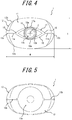
- a recess 13a dented inward of the container 1 is formed on the central portion of the bottom 13.
- the recess 13a is a substantially hemispherical curved surface.
- a pair of grooves 13b extending in the width direction (long axis direction) are formed at the central position in the thickness direction.
- the grooves 13b extend from the bottom 13 to the lower portion of the body 12.
- the grooves 13b act as valley creases when the bottom 13 is folded.
- the container 1 according to this example is configured such that the bottom 13 can be folded by folding a pair of grooves 13b to the inside of the container 1.
- the folding line portions 15 provided at the boundary between the body 12 and the bottom 13 act as mountain creases.
- each folding line portion 15 is provided on the front side and the rear side of the container 1.
- the recess 13a, the grooves 13b and the folding line portions 15 are not essential components, and the shape of the bottom 13 can be changed appropriately.
- the container 1 can be formed by the blow molding such as the biaxial stretch blow molding, for example.
- a preform can be molded into a container having a predetermined shape conforming to an inner surface of a cavity of a mold by placing a body of a bottomed tubular shaped (test tube shaped) preform heated by a heater or the like, for example, to a predetermined temperature at which stretchability is achieved into a cavity of the mold and by supplying, at a predetermined pressure, gas or liquid into the preform through a nozzle.
- a preform can be obtained by injection molding, extrusion blow molding, extrusion molding or the like by using thermoplastic synthetic resins such as polypropylene (PP) and polyethylene terephthalate (PET) or the like as a raw material.
- the preform includes a bottomed tubular body and a mouth continuous to the body.
- the mouth is formed into a cylindrical shape, and the outer periphery thereof is integrally provided with a male thread.
- the body is formed into a test tube shape extending along the axis direction and having a circular cross-section, and is provided to the lower side of the mouth coaxially to and integrally with the mouth.
- the container 1 includes a pair of protruding ribs 16 and 17 disposed opposite to each other on the front side and the rear side of the shoulder 11 across the central axis line C.
- a pair of protruding ribs 16 and 17 become a starting point for folding, and the shoulder 11 can be easily folded.
- the both ends of the pair of protruding ribs 16 and 17 are connected to the intermediate positions of the shoulder 11, respectively, the shoulder 11 can be easily folded up to the intermediate position of the shoulder 11.
- the volume of the container 1 can be reduced for disposal, and in addition, when the container is used in particular for the contents having a high viscosity, the contents remaining in the intermediate position of the shoulder 11 can also be squeezed out. In this manner the residual volume of the contents can be reduced.
- the container 1 according to this embodiment is suitable for a refill container used for refilling contents to a container dedicated for discharging the contents.
- a longitudinal folding line portion 11a is provided at the lower side of each connecting portion 18 of the pair of protruding ribs 16 and 17, which further facilitates fold of the shoulder 11.
- the body 12 is formed into a flat shape having a width larger than a thickness, which allows for easy flattening of the body 12 and the shoulder 11 in the thickness direction. As a result, fold of the entire container 1 including the shoulder 11 is further facilitated. For the same reason, as with this embodiment, it is preferable that the shoulder 11 also has a flat shape like the body 12.
- respective central portions 16a and 17a of the protruding ribs 16 and 17 are adjacent to the base end portion of the mouth 10, and thus the shoulder 11 can be folded to near the base end portion of the mouth 10. Therefore, fold of the shoulder 11 can further improve the volume reduction effect and the residual volume reduction effect of contents.
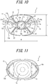
- FIGS. 7 to 12 Another embodiment of the present disclosure will be described with reference to FIGS. 7 to 12 . It is to be noted that the parts having the same basic functions as those described above are assigned with the same reference signs in the drawing, and explanation thereof will be omitted.
- a triangular flat plane 21 is provided to each of a pair of connecting portions 18 that connect both ends of the protruding rib 16 and the both ends of the protruding rib 17, respectively.
- Each triangular flat plane 21 has two sides 21b and 21b that coincide with the protruding ribs 16 and 17, respectively, and an upper side 21a that connects ends of a pair of the sides 21b and 21b.
- the container 2 is provided with longitudinal protruding ribs 22 each extending from the shoulder 11 to the body 12.
- Each longitudinal protruding rib 22 is formed such that it protrudes from the outer surface of the shoulder 11 or the body 12 to the outside the container, and a recess corresponding to the longitudinal protruding rib 22 is formed in the inner surface of the shoulder 11 or the body 12.
- Each longitudinal protruding rib 22 can act as a mountain crease or a valley crease when the shoulder 11 and the body 12 are flattened to fold the container 2.
- Two longitudinal protruding ribs 22 are disposed opposite to each other on the front side and the rear side, respectively.
- Each upper end of four longitudinal protruding ribs 22 is connected to the upper side 21a of the triangular flat plane 21. That is, respective upper ends of the four longitudinal protruding ribs 22 are configured to be connected to the protruding rib 16 or the protruding rib 17.
- the container 2 can be folded by flattening the shoulder 11 and the body 12 in the thickness direction (by sandwiching them between the front side and the rear side) while folding the longitudinal folding line portion 12c and the longitudinal folding line portion 11a to the inside of the container 2.
- the longitudinal folding line portion 12c and the longitudinal folding line portion 11a act as a valley crease and four longitudinal protruding ribs 22 act as a mountain crease.
- the upper side 21a of the triangular flat plane 21 acts as a mountain crease
- the two sides 21b other than the upper sides 21a act as a valley crease
- the flat plane 21 is folded to the inside of the container 2.
- the container 2 can be folded while decreasing the width thereof.
- the surface of the flat plane 21 is located at the same level as the protruding ribs 16 and 17 (is configured to be the same height), the surface of the flat plane 21 may be higher or lower than that of the protruding ribs 16 and 17. Further, instead of the triangular flat plane 21, only a protruding rib corresponding to the upper side 21a may be provided.
- each of a pair of grooves 13b formed in the bottom 13 has a substantially V-shape.
- Each groove 13b having a substantially V-shape extends from the bottom 13 to the lower side of the body 12, and its top portion (bent portion) is located near the lower side of the body 12 (near each end in the width direction in the bottom diagram illustrated in FIG. 11 ).
- Each groove 13b acts as a valley crease when the bottom 13 is folded while the longitudinal folding line portion 12c is folded to the inside of the container 2.
- the container 2 according to this embodiment can be folded by flattening the shoulder 11 and the body 12. That is, the container 2 can be folded such that the longitudinal folding line portion 12c of the body 12 and the longitudinal folding line portion 11a of the shoulder 11 are displaced to the outside of the container 2 in the width direction.
- the shoulder 11 can be folded easily also in the container 2 according to this embodiment.
- the above description are mere embodiments of the present disclosure, and various changes may be made in the scope of claim.
- a protrusion may be provided for undercut engagement with a cap or the like.
- a cap or the like may be plugged into the mouth 10.
- the shoulder 11, the body 12 and the bottom 13 are symmetrical in the thickness direction (symmetrical back and forth), and are symmetrical in the width direction (symmetrical right and left).
- the bottom 13 may be configured such that it does not form a grounding surface that can ground when the container 1 is in an erecting posture, and it may be formed into a hemispherical curved surface that expands downward.
Landscapes
- Engineering & Computer Science (AREA)
- Ceramic Engineering (AREA)
- Mechanical Engineering (AREA)
- Containers Having Bodies Formed In One Piece (AREA)
Applications Claiming Priority (2)
| Application Number | Priority Date | Filing Date | Title |
|---|---|---|---|
| JP2017129864A JP2019011116A (ja) | 2017-06-30 | 2017-06-30 | 合成樹脂製容器 |
| PCT/JP2018/021383 WO2019003810A1 (fr) | 2017-06-30 | 2018-06-04 | Récipient en résine synthétique |
Publications (2)
| Publication Number | Publication Date |
|---|---|
| EP3647214A1 true EP3647214A1 (fr) | 2020-05-06 |
| EP3647214A4 EP3647214A4 (fr) | 2021-04-14 |
Family
ID=64741476
Family Applications (1)
| Application Number | Title | Priority Date | Filing Date |
|---|---|---|---|
| EP18824423.0A Withdrawn EP3647214A4 (fr) | 2017-06-30 | 2018-06-04 | Récipient en résine synthétique |
Country Status (4)
| Country | Link |
|---|---|
| US (1) | US20210139185A1 (fr) |
| EP (1) | EP3647214A4 (fr) |
| JP (1) | JP2019011116A (fr) |
| WO (1) | WO2019003810A1 (fr) |
Families Citing this family (7)
| Publication number | Priority date | Publication date | Assignee | Title |
|---|---|---|---|---|
| WO2018125967A1 (fr) * | 2016-12-29 | 2018-07-05 | Graham Packaging Company, L.P. | Récipient en plastique remplissable à chaud |
| JP6837936B2 (ja) * | 2017-06-30 | 2021-03-03 | 株式会社吉野工業所 | 液体入り容器の製造方法 |
| JP7403999B2 (ja) * | 2019-08-30 | 2023-12-25 | 株式会社吉野工業所 | 押出し容器 |
| JP2021070504A (ja) * | 2019-10-31 | 2021-05-06 | 小林製薬株式会社 | スクイズ容器 |
| JP7394687B2 (ja) * | 2020-03-31 | 2023-12-08 | 株式会社吉野工業所 | 薄肉容器 |
| JP2022171426A (ja) * | 2021-04-30 | 2022-11-11 | 株式会社吉野工業所 | 絞出し容器 |
| US12280910B2 (en) * | 2023-05-01 | 2025-04-22 | Abbott Laboratories | Collapsible, hangable plastic bottle |
Family Cites Families (6)
| Publication number | Priority date | Publication date | Assignee | Title |
|---|---|---|---|---|
| CH680429A5 (fr) * | 1991-04-29 | 1992-08-31 | Supermatic Kunststoff Ag | |
| JP2988271B2 (ja) * | 1994-09-02 | 1999-12-13 | 東洋製罐株式会社 | 折り畳み可能なブロー成形ボトル |
| JPH11105930A (ja) * | 1997-10-03 | 1999-04-20 | Toppan Printing Co Ltd | 液体容器 |
| JP4069511B2 (ja) * | 1998-08-20 | 2008-04-02 | 凸版印刷株式会社 | 液体容器の製造方法 |
| JP4346050B2 (ja) * | 1999-03-19 | 2009-10-14 | アサヒ飲料株式会社 | 樹脂製ボトル |
| JP3993759B2 (ja) | 2001-10-29 | 2007-10-17 | サラヤ株式会社 | ブローボトル |
-
2017
- 2017-06-30 JP JP2017129864A patent/JP2019011116A/ja active Pending
-
2018
- 2018-06-04 US US16/617,344 patent/US20210139185A1/en not_active Abandoned
- 2018-06-04 EP EP18824423.0A patent/EP3647214A4/fr not_active Withdrawn
- 2018-06-04 WO PCT/JP2018/021383 patent/WO2019003810A1/fr not_active Ceased
Also Published As
| Publication number | Publication date |
|---|---|
| WO2019003810A1 (fr) | 2019-01-03 |
| EP3647214A4 (fr) | 2021-04-14 |
| JP2019011116A (ja) | 2019-01-24 |
| US20210139185A1 (en) | 2021-05-13 |
Similar Documents
| Publication | Publication Date | Title |
|---|---|---|
| US20210139185A1 (en) | Synthetic resin container | |
| EP3733538B1 (fr) | Récipient en résine synthétique, préforme et procédé de production de récipient en résine synthétique | |
| EP2792466B1 (fr) | Paraison et procédé de moulage par soufflage de récipient utilisant celle-ci | |
| US10988277B2 (en) | Synthetic resin container and preform | |
| CN109070432B (zh) | 容器制造方法 | |
| RU2018110828A (ru) | Сжимаемая бутылка | |
| US11472591B2 (en) | Synthetic resin container | |
| WO2020195688A1 (fr) | Ensemble préforme, récipient à liquide à double paroi et procédé de fabrication de récipient à liquide à double paroi | |
| JP6906844B2 (ja) | 積層剥離容器 | |
| JP7094620B2 (ja) | 合成樹脂製容器 | |
| EP4011596A1 (fr) | Préforme, récipient en résine synthétique et procédé pour la fabrication de récipient en résine synthétique | |
| EP2116349A1 (fr) | Préforme en plastique et récipient unique pour fabriquer un récipient à double conteneur | |
| US9290280B2 (en) | Method for producing a container intended to contain a substance to be dispensed by an airless pump, and a container produced by the method | |
| JP4609792B2 (ja) | 合成樹脂製二重構造容器の製造方法 | |
| CN113365920B (zh) | 装有内容液的瓶体的制造方法 | |
| EP3647016B1 (fr) | Méthode de fabrication d'un récipient contenant un liquide | |
| MX2015006098A (es) | Recipiente de plastico y metodo. | |
| JP6910715B2 (ja) | 二重容器、注出具付き容器及びプリフォーム | |
| US12264007B2 (en) | Delamination container | |
| JP7317454B2 (ja) | 積層剥離容器 | |
| JP7399557B2 (ja) | 二重容器及び二重容器の製造方法 | |
| CN122070205A (en) | Cosmetic container | |
| CN121240957A (zh) | 包括旨在容纳产品的中空主体的模塑塑料容器 |
Legal Events
| Date | Code | Title | Description |
|---|---|---|---|
| STAA | Information on the status of an ep patent application or granted ep patent |
Free format text: STATUS: THE INTERNATIONAL PUBLICATION HAS BEEN MADE |
|
| PUAI | Public reference made under article 153(3) epc to a published international application that has entered the european phase |
Free format text: ORIGINAL CODE: 0009012 |
|
| STAA | Information on the status of an ep patent application or granted ep patent |
Free format text: STATUS: REQUEST FOR EXAMINATION WAS MADE |
|
| 17P | Request for examination filed |
Effective date: 20191129 |
|
| AK | Designated contracting states |
Kind code of ref document: A1 Designated state(s): AL AT BE BG CH CY CZ DE DK EE ES FI FR GB GR HR HU IE IS IT LI LT LU LV MC MK MT NL NO PL PT RO RS SE SI SK SM TR |
|
| AX | Request for extension of the european patent |
Extension state: BA ME |
|
| DAV | Request for validation of the european patent (deleted) | ||
| DAX | Request for extension of the european patent (deleted) | ||
| A4 | Supplementary search report drawn up and despatched |
Effective date: 20210312 |
|
| RIC1 | Information provided on ipc code assigned before grant |
Ipc: B65D 1/02 20060101AFI20210308BHEP |
|
| STAA | Information on the status of an ep patent application or granted ep patent |
Free format text: STATUS: EXAMINATION IS IN PROGRESS |
|
| 17Q | First examination report despatched |
Effective date: 20220901 |
|
| STAA | Information on the status of an ep patent application or granted ep patent |
Free format text: STATUS: THE APPLICATION HAS BEEN WITHDRAWN |
|
| 18W | Application withdrawn |
Effective date: 20221103 |