EP3647228A1 - Vorrichtung zur wärmebehandlung von kraftfahrzeugen oder kraftfahrzeugteilen - Google Patents
Vorrichtung zur wärmebehandlung von kraftfahrzeugen oder kraftfahrzeugteilen Download PDFInfo
- Publication number
- EP3647228A1 EP3647228A1 EP18203990.9A EP18203990A EP3647228A1 EP 3647228 A1 EP3647228 A1 EP 3647228A1 EP 18203990 A EP18203990 A EP 18203990A EP 3647228 A1 EP3647228 A1 EP 3647228A1
- Authority
- EP
- European Patent Office
- Prior art keywords
- container
- cooling unit
- fan
- heat exchanger
- air
- Prior art date
- Legal status (The legal status is an assumption and is not a legal conclusion. Google has not performed a legal analysis and makes no representation as to the accuracy of the status listed.)
- Granted
Links
Images

Classifications
-
- A—HUMAN NECESSITIES
- A61—MEDICAL OR VETERINARY SCIENCE; HYGIENE
- A61L—METHODS OR APPARATUS FOR STERILISING MATERIALS OR OBJECTS IN GENERAL; DISINFECTION, STERILISATION OR DEODORISATION OF AIR; CHEMICAL ASPECTS OF BANDAGES, DRESSINGS, ABSORBENT PADS OR SURGICAL ARTICLES; MATERIALS FOR BANDAGES, DRESSINGS, ABSORBENT PADS OR SURGICAL ARTICLES
- A61L2/00—Disinfection or sterilisation of materials or objects, in general; Accessories therefor
- A61L2/02—Disinfection or sterilisation of materials or objects, in general; Accessories therefor using physical processes
- A61L2/04—Heat
- A61L2/06—Hot gas
-
- A—HUMAN NECESSITIES
- A01—AGRICULTURE; FORESTRY; ANIMAL HUSBANDRY; HUNTING; TRAPPING; FISHING
- A01M—CATCHING, TRAPPING OR SCARING OF ANIMALS; APPARATUS FOR THE DESTRUCTION OF NOXIOUS ANIMALS OR NOXIOUS PLANTS
- A01M1/00—Stationary means for catching or killing insects
- A01M1/20—Poisoning, narcotising, or burning insects
- A01M1/2094—Poisoning, narcotising, or burning insects killing insects by using temperature, e.g. flames, steam or freezing
-
- A—HUMAN NECESSITIES
- A01—AGRICULTURE; FORESTRY; ANIMAL HUSBANDRY; HUNTING; TRAPPING; FISHING
- A01M—CATCHING, TRAPPING OR SCARING OF ANIMALS; APPARATUS FOR THE DESTRUCTION OF NOXIOUS ANIMALS OR NOXIOUS PLANTS
- A01M1/00—Stationary means for catching or killing insects
- A01M1/24—Arrangements connected with buildings, doors, windows, or the like
-
- A—HUMAN NECESSITIES
- A01—AGRICULTURE; FORESTRY; ANIMAL HUSBANDRY; HUNTING; TRAPPING; FISHING
- A01M—CATCHING, TRAPPING OR SCARING OF ANIMALS; APPARATUS FOR THE DESTRUCTION OF NOXIOUS ANIMALS OR NOXIOUS PLANTS
- A01M13/00—Fumigators; Apparatus for distributing gases
- A01M13/003—Enclosures for fumigation, e.g. containers, bags or housings
-
- A—HUMAN NECESSITIES
- A01—AGRICULTURE; FORESTRY; ANIMAL HUSBANDRY; HUNTING; TRAPPING; FISHING
- A01M—CATCHING, TRAPPING OR SCARING OF ANIMALS; APPARATUS FOR THE DESTRUCTION OF NOXIOUS ANIMALS OR NOXIOUS PLANTS
- A01M19/00—Apparatus for the destruction of noxious animals, other than insects, by hot water, steam, hot air, or electricity
-
- B—PERFORMING OPERATIONS; TRANSPORTING
- B65—CONVEYING; PACKING; STORING; HANDLING THIN OR FILAMENTARY MATERIAL
- B65D—CONTAINERS FOR STORAGE OR TRANSPORT OF ARTICLES OR MATERIALS, e.g. BAGS, BARRELS, BOTTLES, BOXES, CANS, CARTONS, CRATES, DRUMS, JARS, TANKS, HOPPERS, FORWARDING CONTAINERS; ACCESSORIES, CLOSURES, OR FITTINGS THEREFOR; PACKAGING ELEMENTS; PACKAGES
- B65D88/00—Large containers
- B65D88/74—Large containers having means for heating, cooling, aerating or other conditioning of contents
- B65D88/745—Large containers having means for heating, cooling, aerating or other conditioning of contents blowing or injecting heating, cooling or other conditioning fluid inside the container
-
- E—FIXED CONSTRUCTIONS
- E04—BUILDING
- E04H—BUILDINGS OR LIKE STRUCTURES FOR PARTICULAR PURPOSES; SWIMMING OR SPLASH BATHS OR POOLS; MASTS; FENCING; TENTS OR CANOPIES, IN GENERAL
- E04H6/00—Buildings for parking cars, rolling-stock, aircraft, vessels or like vehicles, e.g. garages
-
- E—FIXED CONSTRUCTIONS
- E04—BUILDING
- E04H—BUILDINGS OR LIKE STRUCTURES FOR PARTICULAR PURPOSES; SWIMMING OR SPLASH BATHS OR POOLS; MASTS; FENCING; TENTS OR CANOPIES, IN GENERAL
- E04H6/00—Buildings for parking cars, rolling-stock, aircraft, vessels or like vehicles, e.g. garages
- E04H6/42—Devices or arrangements peculiar to garages, not covered elsewhere, e.g. securing devices, safety devices, monitoring and operating schemes; centering devices
-
- F—MECHANICAL ENGINEERING; LIGHTING; HEATING; WEAPONS; BLASTING
- F25—REFRIGERATION OR COOLING; COMBINED HEATING AND REFRIGERATION SYSTEMS; HEAT PUMP SYSTEMS; MANUFACTURE OR STORAGE OF ICE; LIQUEFACTION SOLIDIFICATION OF GASES
- F25D—REFRIGERATORS; COLD ROOMS; ICE-BOXES; COOLING OR FREEZING APPARATUS NOT OTHERWISE PROVIDED FOR
- F25D11/00—Self-contained movable devices, e.g. domestic refrigerators
- F25D11/003—Transport containers
-
- G—PHYSICS
- G08—SIGNALLING
- G08B—SIGNALLING SYSTEMS, e.g. PERSONAL CALLING SYSTEMS; ORDER TELEGRAPHS; ALARM SYSTEMS
- G08B3/00—Audible signalling systems, e.g. audible personal calling systems
- G08B3/10—Audible signalling systems, e.g. audible personal calling systems using electric transmission; using electromagnetic transmission
-
- G—PHYSICS
- G08—SIGNALLING
- G08B—SIGNALLING SYSTEMS, e.g. PERSONAL CALLING SYSTEMS; ORDER TELEGRAPHS; ALARM SYSTEMS
- G08B5/00—Visible signalling systems, e.g. visible personal calling systems or remote indication of seats occupied
- G08B5/22—Visible signalling systems, e.g. visible personal calling systems or remote indication of seats occupied using electric transmission; using electromagnetic transmission
-
- A—HUMAN NECESSITIES
- A01—AGRICULTURE; FORESTRY; ANIMAL HUSBANDRY; HUNTING; TRAPPING; FISHING
- A01M—CATCHING, TRAPPING OR SCARING OF ANIMALS; APPARATUS FOR THE DESTRUCTION OF NOXIOUS ANIMALS OR NOXIOUS PLANTS
- A01M2200/00—Kind of animal
- A01M2200/01—Insects
-
- A—HUMAN NECESSITIES
- A61—MEDICAL OR VETERINARY SCIENCE; HYGIENE
- A61L—METHODS OR APPARATUS FOR STERILISING MATERIALS OR OBJECTS IN GENERAL; DISINFECTION, STERILISATION OR DEODORISATION OF AIR; CHEMICAL ASPECTS OF BANDAGES, DRESSINGS, ABSORBENT PADS OR SURGICAL ARTICLES; MATERIALS FOR BANDAGES, DRESSINGS, ABSORBENT PADS OR SURGICAL ARTICLES
- A61L2202/00—Aspects relating to methods or apparatus for disinfecting or sterilising materials or objects
- A61L2202/10—Apparatus features
- A61L2202/12—Apparatus for isolating biocidal substances from the environment
- A61L2202/122—Chambers for sterilisation
-
- B—PERFORMING OPERATIONS; TRANSPORTING
- B65—CONVEYING; PACKING; STORING; HANDLING THIN OR FILAMENTARY MATERIAL
- B65D—CONTAINERS FOR STORAGE OR TRANSPORT OF ARTICLES OR MATERIALS, e.g. BAGS, BARRELS, BOTTLES, BOXES, CANS, CARTONS, CRATES, DRUMS, JARS, TANKS, HOPPERS, FORWARDING CONTAINERS; ACCESSORIES, CLOSURES, OR FITTINGS THEREFOR; PACKAGING ELEMENTS; PACKAGES
- B65D2588/00—Large container
- B65D2588/74—Large container having means for heating, cooling, aerating or other conditioning of contents
- B65D2588/743—Large container having means for heating, cooling, aerating or other conditioning of contents blowing or injecting heating, cooling or other conditioning fluid inside the container
Definitions
- the invention relates to a device for the heat treatment of motor vehicles or motor vehicle parts, in particular for the purpose of killing pests.
- Heat treatment or heat treatment of motor vehicles is understood to mean heating a motor vehicle in such a way that the motor vehicle at its coldest point exceeds a specific minimum temperature for a specific time.
- Such a heat treatment can be used in particular to meet legal or official regulations that require treatment of pest control goods to be exported or imported.
- Australia and New Zealand to combat the brown marbled stink bug (BMSB) currently require that vehicles imported from certain countries within a certain period of the year be treated within 120 hours of the ship's departure, for example. It is currently recognized as sufficient to heat each motor vehicle so that at its coldest point it has a temperature of at least 50 degrees Celsius (Australia) for a period of at least 20 minutes or a temperature of at least 56 for a period of at least 30 minutes Degrees Celsius (New Zealand).
- the treatment for each motor vehicle must be documented individually with all parameters. Due to the size of the ship, up to 2,000 vehicles have to undergo such treatment for a ship's cargo.
- the object of the invention is therefore a device for the heat treatment of motor vehicles or motor vehicle parts, in particular for the purpose of killing To provide pests, which has advantages over known solutions.
- An insulated sea freight container for temperature-controlled transport is a large-volume container that is particularly thermally insulated compared to standard sea freight containers and is typically used for temperature-sensitive freight.
- refrigerated containers with an integrated refrigeration system (cooling unit), the cooling unit being operated with electrical current.
- Such refrigerated containers are also referred to as integral containers.
- Refrigerated containers have an essentially rectangular basic shape with a long axis of typically 40 feet (approx. 12 m) in length. The loading opening of the container is typically inserted through one receiving opening on one of the two end faces, while the cooling unit is arranged on the other end face.
- the cooling unit can be releasably attached to a circumferential flange with bolt connections around the outer edge of the receiving opening. Air cooled in the cooling unit can flow into the interior of the container.
- the inner floor of a refrigerated container can be designed with longitudinal ribs in such a way that longitudinal channels for cooling air remain between the ribs. This typically allows air to circulate within the container.
- the container has a cooling unit or that the cooling unit is functional.
- refrigerated container has the advantage that used refrigerated containers can be purchased cheaply. This is especially true if the cooling unit is defective.
- the installation of the sensors is significantly less complex in the solution according to the invention.
- the installation of ventilation technology for heating the interior of the motor vehicle is also significantly less complex.
- the installation of an underbody ventilation technology is significantly less complex in the solution according to the invention.
- a system that consists of several refrigerated containers has the further advantage over a heat-treated warehouse, which is typically significantly larger than a refrigerated container, in that only a small number of motor vehicles, typically two, are heat-treated in each refrigerated container. an individual heat treatment of a small number of motor vehicles with regard to minimum temperature and minimum duration is possible without any problems.
- the maximum capacity of a system that consists of several refrigerated containers is freely scalable. During the idle time, the containers can be efficiently stored or stacked, even outside the port, which avoids useless occupancy of expensive port areas. Since the retrofitting of a refrigerated container to a device according to the invention is only minor intervention, the containers can also be retrofitted and used again for their original purpose.
- the proposed mobile hot water sources can be rented and installed without a permit. This eliminates capital costs for the idle time.
- the at least one fan and the at least one heat exchanger are preferably arranged in the container. This avoids energy losses due to an arrangement outside the container.
- the at least one fan and the at least one heat exchanger are preferably integrated in one unit. Such units are already offered on the market.
- the container preferably comprises a cooling unit which can be operated with electrical current and which comprises a cooling unit which may be functional and at least one fan.
- the already existing fan of the cooling unit can then also be used to move and distribute the air.
- the cooling unit is preferably arranged on one of the two end faces of the container.
- the cooling unit preferably forms a vertical shaft on the inside of the end face, the rear wall of the cooling unit functionally supplementing or being identical to the wall of the container, the transverse wall opposite the rear wall of the cooling unit having at least one passage opening through which air flows out of the shaft into the container and / or can flow out of the container into the shaft.
- one of the substances that flow through the heat exchanger is fed through a line from outside the container and discharged through a line to the outside of the container.
- the motor vehicles are preferably passenger cars.
- the at least one heat exchanger is preferably a water-air heat exchanger.
- the heat exchanger is preferably supplied by a mobile hot water source.
- the total heat output of the heat exchangers is preferably at least 100 kW.
- the container preferably has at least one heat exchanger and one fan on each of the two end faces.
- the device preferably comprises two heat exchangers, the heat output of which is at least 50 kW each.
- An inspection flap in the transverse wall of the cooling unit is preferably replaced by a sheet metal which in each case passes through a flow and a return hose per heat exchanger.
- At least one tube can preferably distribute air in the interior of the container parallel to the long side of the container with at least two outlets. Particularly advantageous it is when a radial fan is attached to the pipe.
- the outputs are preferably adjustable.
- the outputs are preferably arranged at regular intervals.
- the at least one tube is preferably a spiral folded tube.
- a tube is preferably arranged in the area of the ceiling in each case in the area of a longitudinal side wall.
- ribs arranged on the bottom of the container, between which air can flow are partially covered, so that air flowing between the ribs can only flow upwards through certain openings.
- Air is preferably forced into the spaces between the ribs by at least one fan arranged in the cooling unit.
- the openings are preferably adjustable.
- the openings are preferably arranged at regular intervals.
- a lighting device is preferably arranged in the container interior.
- An emergency stop switch is preferably provided.
- the device preferably has foldable ramps at the loading opening.
- the loading ramps (access ramps) can preferably be detachably connected to the container.
- the loading ramps can preferably be detachably attached to cooling fins on the bottom of the container by means of at least one clamping device.
- At least one wire-bound sensor is preferably arranged in the container interior. Values measured by the measurement sensors or calculated on the basis of the measured values can preferably be transmitted to a device which is suitable for documenting the values.
- the time during which all values remain continuously in the predetermined range is preferably measured, and an optically or acoustically perceptible signal is generated after a predetermined minimum time has elapsed.
- the flow temperature for the at least one heat exchanger is preferably a maximum of 95 degrees Celsius.
- a system is preferably present which comprises four devices according to the invention, four containers being supplied by a common 400 kW hot water source.
- Figure 1 shows a device according to the invention in a state with the loading opening of the insulated sea freight container 1 open and the loading ramps 2a and 2b folded out.
- a motor vehicle that is to be heat-treated, for example, for the purpose of killing pests can roll into the container interior via the loading ramps 2a, 2b.
- the loading opening can be closed by pivoting the two wing doors 3a and 3b after the loading ramps 2a and 2b have been folded up.
- a unit 4a, 4b is arranged on each of the two end faces of the interior of the container 1, in each of which a heat exchanger and a fan are integrated.
- Transverse wall 5 behind which there is a cooling unit, not shown, which comprises two fans.
- the cooling unit not shown in the figure, forms a vertical shaft.
- the rear wall of the cooling unit functionally complements the wall of the container opposite the loading opening.
- the transverse wall 5 has through openings, not shown, through which air can flow from the shaft into the interior of the container.
- a tube 6a, 6b is arranged parallel to the longitudinal side in the area of a longitudinal side wall and can distribute air in the container interior via several adjustable outlets 7, which are arranged at regular intervals.
- a radial fan (not shown) is attached to the end of the tube facing away from the loading opening.
- Ribs 8 are arranged on the bottom of the container, through which air can flow, which is pressed into the spaces between the ribs by the fan (not shown) in the cooling unit.
- the ribs are partially covered by plates 9, so that air flowing between the ribs can only flow upward through the openings between the plates.
- Wired sensors 10 hang from cables on a longitudinal wall of the container interior.
- a horn 11, a sprinkler system 12, a rotating beacon 13, two operating indicators 14a, 14b and an emergency stop switch 15 are also shown.
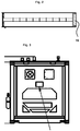
- the in Figure 2 The floor plan shown shows the arrangement of the cooling unit 16 within the refrigerated container.
- FIG 3 shows schematically the wall of the container opposite the loading opening from the outside. This back wall is functionally supplemented by the back wall of the cooling unit.
Landscapes
- Engineering & Computer Science (AREA)
- Life Sciences & Earth Sciences (AREA)
- Pest Control & Pesticides (AREA)
- Health & Medical Sciences (AREA)
- Architecture (AREA)
- Physics & Mathematics (AREA)
- General Health & Medical Sciences (AREA)
- Insects & Arthropods (AREA)
- Wood Science & Technology (AREA)
- Zoology (AREA)
- Environmental Sciences (AREA)
- Toxicology (AREA)
- Mechanical Engineering (AREA)
- Civil Engineering (AREA)
- Structural Engineering (AREA)
- General Physics & Mathematics (AREA)
- Electromagnetism (AREA)
- Epidemiology (AREA)
- Veterinary Medicine (AREA)
- Public Health (AREA)
- Animal Behavior & Ethology (AREA)
- Chemical & Material Sciences (AREA)
- Combustion & Propulsion (AREA)
- Thermal Sciences (AREA)
- General Engineering & Computer Science (AREA)
- Devices That Are Associated With Refrigeration Equipment (AREA)
- Catching Or Destruction (AREA)
- Air-Conditioning For Vehicles (AREA)
Abstract
Description
- Gegenstand der Erfindung ist eine Vorrichtung zur Wärmebehandlung von Kraftfahrzeugen oder Kraftfahrzeugteilen, insbesondere zum Zwecke der Abtötung von Schädlingen.
- Unter Wärmebehandlung oder Hitzebehandlung von Kraftfahrzeugen wird verstanden, ein Kraftfahrzeug in der Weise zu erwärmen, dass das Kraftfahrzeug an seiner kältesten Stelle für eine bestimmte Zeit eine bestimmte Mindesttemperatur übersteigt. Eine solche Wärmebehandlung ist kann insbesondere dazu dienen, gesetzliche oder behördlichen Bestimmungen zu erfüllen, die eine Behandlung von zu exportierenden oder zu importierenden Gütern zur Schädlingsbekämpfung verlangen. Insbesondere verlangen zurzeit Australien und Neuseeland zur Bekämpfung der Braun marmorierten Baumwanze (Brown marmorated stink bug, BMSB), dass Kraftfahrzeuge, die innerhalb eines bestimmten Zeitraums des Jahres aus bestimmten Ländern importiert werden, innerhalb von 120 Stunden vor Abfahrt beispielsweise des Schiffes behandelt werden. Als ausreichend anerkannt ist dabei zurzeit, jedes Kraftfahrzeug so zu erhitzen, dass er an seiner kältesten Stelle für eine Zeit von mindestens 20 Minuten eine Temperatur von mindestens 50 Grad Celsius (Australien) bzw. für eine Zeit von mindestens 30 Minuten eine Temperatur von mindestens 56 Grad Celsius (Neuseeland) hat. Dabei muss die Behandlung für jedes Kraftfahrzeug individuell mit allen Parametern dokumentiert werden. Aufgrund der Schiffsgrößen sind für eine Schiffsladung bis zum 2.000 Fahrzeuge einer solchen Behandlung zu unterziehen.
- Bekannt ist es, eine solche Wärmebehandlung in der Weise durchzuführen, dass ein Lagerhaus dafür ertüchtigt wird oder für diesen Zweck errichtet wird. Diese Lösung geht jedoch mit hohen Investitionen und langen baurechtlichen Genehmigungszeiten einher.
- Aufgabe der Erfindung ist es daher, eine Vorrichtung zur Wärmebehandlung von Kraftfahrzeugen oder Kraftfahrzeugteilen, insbesondere zum Zwecke der Abtötung von Schädlingen, zur Verfügung zu stellen, die gegenüber bekannten Lösungen Vorteile aufweist.
- Diese Aufgabe wird gelöst durch eine Vorrichtung gemäß Anspruch 1. Besonders vorteilhafte Ausführungsformen der Erfindung sind Gegenstand der Unteransprüche.
- Ein isolierter Seefracht-Container für einen temperaturgeführten Transport, auch als Kühlcontainer bezeichnet, ist ein gegenüber Standard-Seefracht-Containern besonders wärmeisolierter Großraumbehälter, der typischerweise für temperaturempfindliche Fracht verwendet wird. Insbesondere gibt es Kühlcontainer mit integrierter Kälteanlage (Kühleinheit), wobei die Kühleinheit mit elektrischem Strom betrieben wird. Solche Kühlcontainer werden auch als Integralcontainer bezeichnet. Kühlcontainer haben eine im Wesentlichen rechteckige Grundform mit einer langen Achse von typischerweise 40 Fuß (ca. 12 m) Länge. Die Ladeöffnung des Containers ist typischerweise an einer der beiden Stirnseiten, während die Kühleinheit an der anderen Stirnseite angeordnet ist, typischerweise durch eine Aufnahmeöffnung eingeschoben. Dabei kann die Kühleinheit über einen umlaufenden Flansch mit Bolzenverbindungen rings um den Außenrand der Aufnahmeöffnung lösbar befestigt werden. In der Kühleinheit gekühlte Luft kann in den Containerinnerraum strömen. Der Innenboden eines Kühlcontainers kann mit Längsrippen so ausgebildet sein, dass zwischen den Rippen Längskanäle für Kühlluft bleiben. Typischerweise wird so eine Luftzirkulation innerhalb des Containers ermöglicht.
- Für die Funktionsfähigkeit der Erfindung ist es nicht erforderlich, dass der Container ein Kühlaggregat aufweist oder dass das Kühlaggregat funktionsfähig ist.
- Die Verwendung eines Kühlcontainers hat den Vorteil, dass gebrauchte Kühlcontainer günstig zu erwerben sind. Dies gilt erst recht, wenn das Kühlaggregat defekt ist.
- Durch die ohnehin vorhandene Wärmeisolierung ergibt sich im Vergleich zu einem Lagerhaus eine hohe Energieeffizienz pro behandeltem Fahrzeug.
- Im Vergleich zu einem zur Wärmebehandlung ertüchtigten Lagerhaus ist bei der erfindungsgemäßen Lösung die Installation der Messfühler deutlich weniger aufwendig. Auch ist die Installation der Lüftungstechnik zur Erhitzung des Innenraums des Kraftfahrzeugs deutlich weniger aufwendig. Insbesondere die Installation einer Unterbodenlüftungstechnik ist bei der erfindungsgemäßen Lösung deutlich weniger aufwendig.
- Eine Anlage, die aus mehreren Kühlcontainern besteht, hat gegenüber einer zur Wärmebehandlung ertüchtigten Lagerhalle, die typischerweise deutlich größer als ein Kühlcontainer ist, den weiteren Vorteil, dass dadurch, dass in jedem Kühlcontainer nur eine kleine Anzahl von Kraftfahrzeugen, typischerweise zwei, wärmebehandelt wird, eine individuelle Wärmebehandlung einer kleinen Anzahl von Kraftfahrzeugen im Hinblick auf Mindesttemperatur und Mindestdauer problemlos möglich ist.
- Die Maximalkapazität einer Anlage, die aus mehreren Kühlcontainern besteht, ist frei skalierbar. Während der benutzungsfreien Zeit lassen sich die Container effizient lagern bzw. stapeln, auch außerhalb des Hafens, wodurch eine nutzlose Belegung von teuren Hafenflächen vermieden wird. Da die Umrüstung eines Kühlcontainers zu einer erfindungsgemäßen Vorrichtung nur einen geringen Eingriff darstellt, können die Container auch zurückgerüstet werden und wieder für ihren ursprünglichen Zweck verwendet werden.
- Die vorgeschlagenen mobilen Warmwasserquellen können gemietet und genehmigungsfrei aufgestellt werden. Dadurch entfallen Kapitalkosten für die nutzungsfreie Zeit.
- Vorzugsweise sind der mindestens eine Ventilator und der mindestens eine Wärmetauscher in dem Container angeordnet. Dadurch werden Energieverluste durch eine Anordnung außerhalb des Containers vermieden.
- Vorzugsweise sind der mindestens eine Ventilator und der mindestens eine Wärmetauscher in einer Einheit integriert. Solche Einheiten werden fertig auf dem Markt angeboten.
- Vorzugsweise umfasst der Container eine Kühleinheit, die mit elektrischen Strom betrieben werden kann und die ein Kühlaggregat, das möglicherweise funktionsfähig ist, und mindestens einen Ventilator umfasst. Der ohnehin bereits vorhandene Ventilator der Kühleinheit kann dann ebenfalls zur Bewegung und Verteilung der Luft genutzt werden. Dabei ist die Kühleinheit vorzugsweise an einer der beiden Stirnseiten des Containers angeordnet. Vorzugsweise bildet die Kühleinheit einen vertikalen Schacht an der Innenseite der Stirnseite, wobei die Rückwand der Kühleinheit funktionell die Wand des Containers ergänzt oder mit dieser identisch ist, wobei die der Rückwand der Kühleinheit gegenüberliegende Querwand mindestens eine Durchtrittsöffnung aufweist, durch die Luft aus dem Schacht in den Container und/oder aus dem Container in den Schacht strömen kann.
- Vorzugsweise wird einer der Stoffe, die durch den Wärmetauscher strömen, durch eine Leitung von außerhalb des Containers zugeführt und durch eine Leitung nach außerhalb des Containers abgeführt.
- Vorzugsweise handelt es sich bei den Kraftfahrzeugen um Personenkraftwagen.
- Vorzugsweise ist der mindestens eine Wärmetauscher ein Wasser-Luft-Wärmetauscher. Vorzugsweise wird der Wärmetauscher von einer mobilen Warmwasserquelle versorgt. Vorzugsweise beträgt die Wärmeleistung der Wärmetauscher insgesamt mindestens 100 kW. Vorzugsweise weist der Container an jeder der beiden Stirnseiten mindestens einen Wärmetauscher und einen Ventilator auf. Vorzugsweise umfasst die Vorrichtung zwei Wärmetauscher, deren Wärmeleistung jeweils mindestens 50 kW beträgt.
- Vorzugsweise ist eine Inspektionsklappe in der Querwand der Kühleinheit durch ein Blech ersetzt, das jeweils einen Vorlauf- und einen Rücklaufschlauch pro Wärmetauscher durchlässt.
- Vorzugsweise kann mindestens ein Rohr parallel zur Längsseite des Containers mit mindestens zwei Ausgängen Luft im Containerinnenraum verteilen. Besonders vorteilhaft ist es, wenn auf das Rohr ein Radialventilator aufgesteckt ist. Dabei sind die Ausgänge vorzugweise regulierbar. Vorzugsweise sind die Ausgänge in regelmäßigen Abständen angeordnet. Vorzugsweise ist das mindestens eine Rohr ein Wickelfalzrohr. Vorzugsweise ist jeweils ein Rohr im Bereich der Decke jeweils im Bereich einer Längsseitenwand angeordnet. Durch diese Maßnahmen ist es möglich, die von einem Wärmetauscher erwärmte Luft gezielt auch in Bereiche des zu erwärmenden Kraftfahrzeugs zu leiten, deren Erwärmung sonst deutlich länger dauern würde.
- Vorzugsweise sind am Boden des Containers angeordnete Rippen, zwischen denen Luft strömen kann, teilweise abgedeckt, so dass zwischen den Rippen strömende Luft nur durch bestimmte Öffnungen nach oben strömen kann. Vorzugsweise wird dabei Luft durch mindestens einen in der Kühleinheit angeordneten Ventilator in die Räume zwischen den Rippen gedrückt wird. Vorzugsweise sind die Öffnungen regulierbar. Vorzugsweise sind die Öffnungen in regelmäßigen Abständen angeordnet. Auch diese Maßnahmen ermöglichen eine gezielte Leitung erwärmter Luft in Bereiche des zu erwärmenden Kraftfahrzeugs, deren Erwärmung sonst deutlich länger dauern würde. Durch die Nutzung von im Boden des Kühlcontainers ohnehin vorhandenen Rippen und die Nutzung eines Ventilators der Kühleinheit ist die Installation der Unterbodenlüftungstechnik deutlich einfacher als bei der Ertüchtigung einer Lagerhalle zur Wärmebehandlung.
- Vorzugsweise ist eine Beleuchtungsvorrichtung im Containerinnenraum angeordnet. Vorzugsweise ist ein Not-aus-Schalter vorhanden.
- Vorzugsweise weist die Vorrichtung an der Ladeöffnung klappbare Auffahrrampen auf. Vorzugsweise sind die Laderampen (Auffahrrampen) mit dem Container lösbar verbindbar. Vorzugsweise können die Laderampen über mindestens eine Klemmvorrichtung an Kühlrippen am Boden des Containers lösbar befestigt werden.
- Vorzugsweisedurch können durch Kombination mehrerer Container in der Länge, Breite und/oder Höhe größere zu behandelnde Frachtstücke oder Kraftfahrzeuge erhitzt werden.
- Vorzugsweise ist im Containerinnenraum mindestens ein drahtgebundener Messfühler angeordnet. Vorzugsweise können von den Messfühler gemessene oder aufgrund der gemessenen Werte errechnete Werte an ein Gerät übermittelt werden, das zur Dokumentation der Werte geeignet ist.
- Vorzugsweise wird, wenn alle Messwerte einen vorgegebenen Grenzwert erreicht haben, die Zeit gemessen, während der sämtliche Werte ununterbrochen in dem vorgegebenen Bereich bleiben, und wird nach Ablauf einer vorgegebenen Mindestzeit ein optisch oder akustisch wahrnehmbares Signal erzeugt.
- Vorzugsweise beträgt die Vorlauftemperatur für den mindestens einen Wärmetauscher maximal 95 Grad Celsius.
- Vorzugsweise liegt ein System vor, das vier erfindungsgemäße Vorrichtungen umfasst, wobei vier Container durch eine gemeinsame 400 kW-Warmwasserquelle versorgt werden.
- Die Erfindung wird anhand der Figuren näher erläutert. Es zeigen
- Figur 1:
- eine erfindungsgemäße Vorrichtung
- Figur 2:
- einen Grundriss einer erfindungsgemäßen Vorrichtung
- Figur 3:
- eine Rückwand einer erfindungsgemäßen Vorrichtung von außen
-
Figur 1 zeigt eine erfindungsgemäße Vorrichtung in einem Zustand mit geöffneter Ladeöffnung des isolierten Seefracht-Containers 1 und ausgeklappten Laderampen 2a und 2b. Ein Kraftfahrzeug, das beispielsweise zum Zwecke der Abtötung von Schädlingen wärmebehandelt werden soll, kann über die Laderampen 2a, 2b in den Containerinnenraum rollen. Die Ladeöffnung kann durch Verschwenken der beiden Flügeltüren 3a und 3b geschlossen werden, nachdem die Laderampen 2a und 2b hochgeklappt worden sind. Wenn die Ladeöffnung geschlossen ist, ist an den beiden Stirnseiten des Innenraums des Containers 1 jeweils eine Einheit 4a, 4b angeordnet, in der jeweils ein Wärmetauscher und ein Ventilator integriert sind. An der der Ladeöffnung gegenüberliegenden Stirnseite des Innenraums des Containers 1 befindet sich eine Querwand 5, hinter der sich eine nicht gezeigte Kühleinheit, die zwei Ventilatoren umfasst, befindet. Die in der Figur nicht gezeigte Kühleinheit bildet einen vertikalen Schacht. Die Rückwand der Kühleinheit ergänzt funktionell die der Ladeöffnung gegenüberliegende Wand des Containers. Die Querwand 5 weist nicht gezeigte Durchtrittsöffnungen auf, durch die Luft aus dem Schacht in den Containerinnenraum strömen kann. Im Bereich der Decke des Containerinnenraums ist jeweils im Bereich einer Längsseitenwand ein Rohr 6a, 6b parallel zur Längsseite angeordnet, das über mehrere regulierbare Ausgänge 7, die in regelmäßigen Abständen angeordnet sind, Luft im Containerinnenraum verteilen kann. An dem der Ladeöffnung abgewandten Ende des Rohres ist jeweils ein nicht gezeigter Radialventilator aufgesteckt. Am Boden des Containers sind Rippen 8 angeordnet, durch die Luft strömen kann, die durch den nicht gezeigten Ventilator in der Kühleinheit in die Räume zwischen den Rippen gedrückt wird. Die Rippen sind durch Platten 9 teilweise abgedeckt, so dass zwischen den Rippen strömende Luft nur durch die zwischen den Platten vorhandenen Öffnungen nach oben strömen kann. An eine Längswand des Containerinnenraums hängen an Kabeln drahtgebundene Messfühler 10. Gezeigt sind ferner eine Hupe 11, eine Sprinkleranlage 12, eine Rundumleuchte 13, zwei Betriebsanzeigen 14a, 14b und ein Not-Aus-Schalter 15. - Der in
Figur 2 gezeigte Grundriss zeigt die Anordnung der Kühleinheit 16 innerhalb des Kühlcontainers. -
Figur 3 zeigt schematisch die der Ladeöffnung gegenüberliegen Wand des Containers von außen. Diese Rückwand wird funktionell ergänzt durch die Rückwand der Kühleinheit.
Claims (15)
- Vorrichtung zur Wärmebehandlung von Kraftfahrzeugen oder Kraftfahrzeugteilen, insbesondere zum Zwecke der Abtötung von Schädlingen, umfassend einen isolierten Seefracht-Container für einen temperaturgeführten Transport, wobei die Vorrichtung mindestens einen Ventilator und zusätzlich zu einem möglicherweise im Container angeordneten Kühlaggregat, das möglicherweise funktionsfähig ist, mindestens einen Wärmetauscher umfasst.
- Vorrichtung nach Anspruch 1, dadurch gekennzeichnet, dass der mindestens eine Ventilator und der mindestens eine Wärmetauscher in dem Container angeordnet sind.
- Vorrichtung nach einem der vorhergehenden Ansprüche, dadurch gekennzeichnet, dass der mindestens eine Ventilator und der mindestens eine Wärmetauscher in einer Einheit integriert sind.
- Vorrichtung nach einem der vorhergehenden Ansprüche, dadurch gekennzeichnet, dass der Container eine Kühleinheit umfasst, die mit elektrischen Strom betrieben werden kann und die ein Kühlaggregat, das möglicherweise funktionsfähig ist, und mindestens einen Ventilator umfasst, wobei die Kühleinheit an einer der beiden Stirnseiten des Containers angeordnet ist, wobei die Kühleinheit einen vertikalen Schacht an der Innenseite der Stirnseite bildet, wobei die Rückwand der Kühleinheit funktionell die Wand des Containers ergänzt oder mit dieser identisch ist, wobei die der Rückwand der Kühleinheit gegenüberliegende Querwand mindestens eine Durchtrittsöffnung aufweist, durch die Luft aus dem Schacht in den Container und/oder aus dem Container in den Schacht strömen kann.
- Vorrichtung nach einem der vorhergehenden Ansprüche, dadurch gekennzeichnet, dass einer der Stoffe, die durch den Wärmetauscher strömen, durch eine Leitung von außerhalb des Containers zugeführt und durch eine Leitung nach außerhalb des Containers abgeführt wird.
- Vorrichtung nach einem der vorhergehenden Ansprüche, dadurch gekennzeichnet, dass Wärmetauscher von einer mobilen Warmwasserquelle versorgt wird.
- Vorrichtung nach einem der vorhergehenden Ansprüche, dadurch gekennzeichnet, dass der Container an jeder der beiden Stirnseiten mindestens einen Wärmetauscher und einen Ventilator aufweist, wobei die Wärmeleistung der beiden Wärmetauscher jeweils mindestens 50 kW beträgt.
- Vorrichtung nach einem der vorhergehenden Ansprüche, dadurch gekennzeichnet, dass mindestens ein Rohr parallel zur Längsseite des Containers mit mindestens zwei Ausgängen Luft im Containerinnenraum verteilen kann.
- Vorrichtung nach einem der vorhergehenden Ansprüche, dadurch gekennzeichnet, dass jeweils ein Rohr im Bereich der Decke jeweils im Bereich einer Längsseitenwand angeordnet ist, wobei auf das Rohr ein Radialventilator aufgesteckt ist.
- Vorrichtung nach einem der Ansprüche 4 bis 9, dadurch gekennzeichnet, dass am Boden des Containers angeordnete Rippen, zwischen denen Luft strömen kann, teilweise abgedeckt sind, so dass zwischen den Rippen strömende Luft nur durch bestimmte Öffnungen nach oben strömen kann, wobei Luft durch mindestens einen in der Kühleinheit angeordneten Ventilator in die Räume zwischen den Rippen gedrückt wird.
- Vorrichtung nach einem der vorhergehenden Ansprüche, dadurch gekennzeichnet, dass sie an einer Ladeöffnung klappbare Laderampen aufweist, wobei die Laderampen über mindestens eine Klemmvorrichtung an Kühlrippen am Boden des Containers lösbar befestigt werden können.
- Vorrichtung nach einem der vorhergehenden Ansprüche, dadurch gekennzeichnet, dass durch Kombination mehrerer Container in der Länge, Breite und/oder Höhe größere zu behandelnde Frachtstücke oder Kraftfahrzeuge erhitzt werden können.
- Vorrichtung nach einem der vorhergehenden Ansprüche, dadurch gekennzeichnet, dass im Containerinnenraum mindestens ein drahtgebundener Messfühler angeordnet ist.
- Vorrichtung nach einem der vorhergehenden Ansprüche, dadurch gekennzeichnet, dass wenn alle Messwerte einen vorgegebenen Grenzwert erreicht haben, die Zeit gemessen wird, während der sämtliche Werte ununterbrochen in dem vorgegebenen Bereich bleiben und nach Ablauf einer vorgegebenen Mindestzeit ein optisch oder akustisch wahrnehmbares Signal erzeugt ist.
- System umfassend vier Vorrichtungen jeweils nach einem der vorhergehenden Ansprüche, dadurch gekennzeichnet, dass vier Container durch eine gemeinsame 400 kW-Warmwasserquelle versorgt werden.
Priority Applications (8)
| Application Number | Priority Date | Filing Date | Title |
|---|---|---|---|
| EP18203990.9A EP3647228B1 (de) | 2018-11-01 | 2018-11-01 | Vorrichtung zur wärmebehandlung von kraftfahrzeugen oder kraftfahrzeugteilen |
| ES18203990T ES2949705T3 (es) | 2018-11-01 | 2018-11-01 | Dispositivo para el tratamiento térmico de vehículos a motor o piezas de vehículos a motor |
| SI201830947T SI3647228T1 (sl) | 2018-11-01 | 2018-11-01 | Naprava za toplotno obdelavo motornih vozil ali delov motornih vozil |
| JP2021524315A JP7453225B2 (ja) | 2018-11-01 | 2018-12-04 | 自動車または自動車部品の熱処理のための装置 |
| CN201880099222.XA CN113163747A (zh) | 2018-11-01 | 2018-12-04 | 用于机动车或机动车部件的热处理的装置 |
| US17/289,995 US20210392870A1 (en) | 2018-11-01 | 2018-12-04 | Apparatus for Heat Treatment of Motor Vehicles or Motor Vehicle Parts |
| PCT/EP2018/083447 WO2020088786A1 (de) | 2018-11-01 | 2018-12-04 | Vorrichtung zur wärmebehandlung von kraftfahrzeugen oder kraftfahrzeugteilen |
| KR1020217015855A KR20210084554A (ko) | 2018-11-01 | 2018-12-04 | 자동차 또는 자동차 부품의 열처리 장치 |
Applications Claiming Priority (1)
| Application Number | Priority Date | Filing Date | Title |
|---|---|---|---|
| EP18203990.9A EP3647228B1 (de) | 2018-11-01 | 2018-11-01 | Vorrichtung zur wärmebehandlung von kraftfahrzeugen oder kraftfahrzeugteilen |
Publications (2)
| Publication Number | Publication Date |
|---|---|
| EP3647228A1 true EP3647228A1 (de) | 2020-05-06 |
| EP3647228B1 EP3647228B1 (de) | 2023-03-22 |
Family
ID=64109791
Family Applications (1)
| Application Number | Title | Priority Date | Filing Date |
|---|---|---|---|
| EP18203990.9A Active EP3647228B1 (de) | 2018-11-01 | 2018-11-01 | Vorrichtung zur wärmebehandlung von kraftfahrzeugen oder kraftfahrzeugteilen |
Country Status (8)
| Country | Link |
|---|---|
| US (1) | US20210392870A1 (de) |
| EP (1) | EP3647228B1 (de) |
| JP (1) | JP7453225B2 (de) |
| KR (1) | KR20210084554A (de) |
| CN (1) | CN113163747A (de) |
| ES (1) | ES2949705T3 (de) |
| SI (1) | SI3647228T1 (de) |
| WO (1) | WO2020088786A1 (de) |
Cited By (1)
| Publication number | Priority date | Publication date | Assignee | Title |
|---|---|---|---|---|
| CN112402639A (zh) * | 2020-11-25 | 2021-02-26 | 孙艺楠 | 一种气压除菌式生物菌降解塑料加工机及其加工方法 |
Citations (10)
| Publication number | Priority date | Publication date | Assignee | Title |
|---|---|---|---|---|
| US3991589A (en) * | 1972-04-13 | 1976-11-16 | Frigitemp Corporation | Air conditioned transport of produce |
| DE3208302A1 (de) * | 1981-03-09 | 1982-09-23 | Robert Haefelfinger | Anordnung fuer wohn- oder sonstige nutzzwecke |
| OA09942A (en) * | 1993-05-21 | 1994-11-15 | Cont Asphalt Ltd | Container |
| US5642827A (en) * | 1993-12-02 | 1997-07-01 | Maersk Container Industri As | Refrigerated container and a gable frame |
| EP1179978A1 (de) * | 1999-04-20 | 2002-02-20 | Asiaworld Shipping Services Pty Ltd | Rauchergerät |
| US20080194192A1 (en) * | 2007-02-13 | 2008-08-14 | Dole Food Company, Inc. | Baffle plate assembly for directing air flow in a cargo container |
| US20110209321A1 (en) * | 2010-01-07 | 2011-09-01 | Comau, Inc. | Modular manufacturing facility and method |
| US20130052595A1 (en) * | 2011-08-30 | 2013-02-28 | Wacker Neuson Production Americas Llc | Indirect Fired Heater With Inline Fuel Heater |
| DE102015006098A1 (de) * | 2015-05-09 | 2016-11-10 | Eisenmann Se | Temperiervorrichtung zum Temperieren von Werkstücken |
| EP3147601A1 (de) * | 2014-06-17 | 2017-03-29 | Daikin Industries, Ltd. | Tiefkühlvorrichtung |
Family Cites Families (79)
| Publication number | Priority date | Publication date | Assignee | Title |
|---|---|---|---|---|
| US4370534A (en) * | 1979-04-09 | 1983-01-25 | Deryck Brandon | Apparatus and method for heating, thawing and/or demoisturizing materials and/or objects |
| US4716676A (en) * | 1983-09-14 | 1988-01-05 | Masami Imagawa | Insect killing system |
| US4961283A (en) * | 1986-08-29 | 1990-10-09 | Charles Forbes | Extermination of insects by heat |
| US4817329A (en) * | 1986-08-29 | 1989-04-04 | Charles Forbes | Extermination of insects by heat |
| US4892456A (en) * | 1988-02-04 | 1990-01-09 | Rolflor Industries, Inc. | Unloading system for freight containers |
| US5203108B1 (en) * | 1991-05-31 | 1999-06-08 | Martin W Washburn Jr | Method and device for heat killing insects in bulk produce containers |
| US5365692A (en) * | 1993-05-07 | 1994-11-22 | Kgk Ecosystems, Inc. | Method and apparatus for exterminating pests |
| US6146600A (en) * | 1993-09-17 | 2000-11-14 | University Of Hawaii | Side body disingestation chamber |
| JPH09502868A (ja) * | 1993-09-17 | 1997-03-25 | ユニバーシティー オブ ハワイ | 直接的空気循環式農産物殺虫処理室 |
| DE4335233C1 (de) * | 1993-10-15 | 1994-09-15 | Bundesrep Deutschland | Reaktionskammer zur Dekontamination von Bekleidungs- und Ausrüstungsgegenständen |
| US20110064607A1 (en) * | 1999-05-28 | 2011-03-17 | Thermapure, Inc. | Method for removing or treating harmful biological organisms and chemical substances |
| US8221678B2 (en) * | 2002-02-20 | 2012-07-17 | Hedman David E | System and process for removing or treating harmful biological and organic substances within an enclosure |
| US7837932B2 (en) * | 1999-05-28 | 2010-11-23 | Thermapure, Inc. | Method for removing or treating harmful biological organisms and chemical substances |
| US6227002B1 (en) * | 1999-08-06 | 2001-05-08 | Cool Care, Ltd. | Transportable telescoping cooler |
| US6588140B1 (en) * | 1999-09-14 | 2003-07-08 | Rupp Industries, Inc. | Pest control system |
| KR100730554B1 (ko) * | 2000-03-06 | 2007-06-22 | 후마킬라 가부시키가이샤 | 팬 타입 해충 방제 장치 |
| JP2001254981A (ja) * | 2000-03-10 | 2001-09-21 | Sanyo Electric Co Ltd | 暖房システム |
| WO2001067857A2 (en) * | 2000-03-16 | 2001-09-20 | Bio-Trax, Inc. | Method and system for gas based extermination of rodentia |
| AU2001257349A1 (en) * | 2000-04-28 | 2001-11-12 | Bugshott, Llc | Self-contained mobile fumigation chamber system and method |
| US6612067B2 (en) * | 2001-05-16 | 2003-09-02 | Topp Construction Services, Inc. | Apparatus for and method of eradicating pests |
| CA2385341A1 (en) * | 2001-07-05 | 2003-01-05 | Alan Lebrun | Heat exchange system and method of use |
| DE10220746A1 (de) * | 2002-05-08 | 2003-11-20 | Lufthansa Cargo Charter Agency | Transportpalette und deren Verwendung |
| TWI264285B (en) * | 2003-11-21 | 2006-10-21 | Sanshu Sangyo Co Ltd | Vapor heat insect killing apparatus for Mediterranean fruit fly, orange small fruit fly, Queensland fruit fly and melon fruit or the like |
| US20050246942A1 (en) * | 2004-05-07 | 2005-11-10 | Mueller A C | Method of extermination utilizing heated air |
| US20050268543A1 (en) * | 2004-06-03 | 2005-12-08 | Cargill, Inc. | Mobile furnace for heat treatment of agricultural materials in milling bins |
| CN2770367Y (zh) * | 2005-03-21 | 2006-04-12 | 董霞明 | 集装箱熏蒸升温器 |
| KR200402703Y1 (ko) * | 2005-08-03 | 2005-12-06 | 이기준 | 자동차용 훈증장치 |
| AU2006285513A1 (en) * | 2005-09-02 | 2007-03-08 | Bio Security Solutions Limited | Container decontamination |
| GB2430158A (en) * | 2005-09-16 | 2007-03-21 | Thermokil Ltd | Treating commodities against unwanted biological activity |
| WO2007036000A1 (en) * | 2005-09-29 | 2007-04-05 | Asiaworld Shipping Services Pty Ltd | A shipping container |
| US20070084105A1 (en) * | 2005-10-17 | 2007-04-19 | Rupp Industries, Inc. | Portable pest control system |
| US20070283986A1 (en) * | 2006-03-29 | 2007-12-13 | Baum Mark L | Home furnishing system treatment and method |
| US20110064605A1 (en) * | 2006-07-05 | 2011-03-17 | Thermapure, Inc. | Method for treating an object contaminated with harmful biological organisms or chemical substances utilizing electromagnetic waves |
| WO2008006035A2 (en) * | 2006-07-06 | 2008-01-10 | Thermapure, Inc. | Method for removing or treating harmful biological organisms and chemical substances |
| SG144015A1 (en) * | 2007-01-05 | 2008-07-29 | Othree Singapore Pte Ltd | Article processing system and method |
| US20090211148A1 (en) * | 2007-06-29 | 2009-08-27 | Mccarty Terry Michael | Mobil Pest Eradication System |
| JP5004342B2 (ja) * | 2007-07-13 | 2012-08-22 | テクノ化成株式会社 | 車輌に付着した有害生物を死滅させる方法および熱処理施設 |
| US9497955B1 (en) * | 2008-04-30 | 2016-11-22 | Fred Rogacki | Fumigation of containerized cargo |
| US8132357B2 (en) * | 2008-04-30 | 2012-03-13 | Fred Rogacki | Fumigation of containerized cargo |
| US7926222B2 (en) * | 2008-09-25 | 2011-04-19 | Molnar Christopher J | Insect eradication system and method |
| US20110308139A1 (en) * | 2009-02-23 | 2011-12-22 | Nuvenco Ip, Llc | Pest eradication system |
| JP5066563B2 (ja) | 2009-12-02 | 2012-11-07 | 株式会社向井珍味堂 | 冷凍庫 |
| CA2811200A1 (en) * | 2010-09-13 | 2012-03-22 | The Steritech Group, Inc. | Insect extermination system |
| US9326498B2 (en) * | 2010-09-14 | 2016-05-03 | JAB Distributors, LLC | Heatable enclosure for pest eradication |
| DE202010015033U1 (de) * | 2010-10-15 | 2011-03-03 | Deutsche Post Ag | Container |
| CA2725936A1 (en) * | 2010-12-22 | 2011-06-09 | Eco Bug Doctor Inc. | Apparatus and method for eliminating arthropod infestations |
| US8756857B2 (en) * | 2011-01-14 | 2014-06-24 | Technologies Holdings Corp. | Hydronic heating system and method for pest control |
| US20120192479A1 (en) * | 2011-01-31 | 2012-08-02 | Schmitz Jack D | Heated enclosure for killing bed bugs located within luggage |
| US20120204478A1 (en) * | 2011-02-16 | 2012-08-16 | Joseph Gere | Heater and method for heating an enclosure to eradicate insects |
| WO2012127383A1 (en) * | 2011-03-18 | 2012-09-27 | Ecolab Usa Inc. | Heat system for killing pests |
| KR101367416B1 (ko) * | 2011-04-22 | 2014-02-26 | 주식회사 시너지포인트 | 차량 방역시스템 |
| US9247725B2 (en) * | 2011-06-06 | 2016-02-02 | Technologies Holdings Corp. | Packaged terminal climate unit for pest control |
| US20120317870A1 (en) * | 2011-06-20 | 2012-12-20 | Gregory Allen Pratt | Method and apparatus for use in the extermination of bed bug infestations |
| US9554568B1 (en) * | 2012-04-23 | 2017-01-31 | Jay Tallon | System and method for bedbug eradication |
| US9339021B2 (en) * | 2012-07-13 | 2016-05-17 | Kenneth Lander | Thermal processing device, system, and method |
| US9028750B2 (en) * | 2012-10-19 | 2015-05-12 | Florida East Coast Industries, Inc. | Fumigation system and process with temperature control, filtration, and air-reintroduction |
| US20160073621A1 (en) * | 2013-03-15 | 2016-03-17 | Scott Nielson | Enclosure for Killing Insects |
| US9459022B2 (en) * | 2013-09-18 | 2016-10-04 | Supplier Support International, Inc. | Multi-component system for treating enclosed environments |
| CA2830900A1 (en) * | 2013-10-16 | 2015-04-16 | Dobson, Terence W. | Bed bug heat treatment bay |
| US9532561B2 (en) * | 2013-12-31 | 2017-01-03 | Harold Richard Mladek | Device for killing insects with heat |
| NL2012158C2 (en) * | 2014-01-28 | 2015-07-29 | Pure Dev 1 B V | Kit for air treatment of upholstered furniture and method of using such kit. |
| US10201173B1 (en) * | 2014-04-16 | 2019-02-12 | Alexander Alfred Napoles | Circulation chamber and method of using same |
| JP6472015B2 (ja) * | 2014-09-05 | 2019-02-20 | 三共アメニテクス株式会社 | 移動式燻蒸車 |
| US10166310B2 (en) * | 2014-10-13 | 2019-01-01 | Aeroclave, Llc | Combination decontamination system for transportation assets |
| US20160219859A1 (en) * | 2015-01-05 | 2016-08-04 | Uvas, Llc | Organism control device and method |
| CN204960476U (zh) * | 2015-08-20 | 2016-01-13 | 杭州众赢科技有限公司 | 一种通道式集装箱多功能活动车房 |
| AU2016331029B2 (en) * | 2015-09-28 | 2021-02-18 | Genera Limited | Portable shipping container contents heating apparatus |
| CN105123663B (zh) * | 2015-09-30 | 2017-12-01 | 厦门和健卫生技术服务有限公司 | 智能型环保除害处理装置 |
| CN205569350U (zh) * | 2015-12-11 | 2016-09-14 | 邢金超 | 养殖场用汽车热风消毒室 |
| US20160249598A1 (en) * | 2016-05-02 | 2016-09-01 | Robert Savino | Mattress and Furniture Processor |
| US20180050667A1 (en) * | 2016-08-17 | 2018-02-22 | Zakir Hossain | Portable vehicle wash container |
| JP6615966B1 (ja) * | 2018-06-29 | 2019-12-04 | 株式会社日本輸出自動車検査センター | 自動車の高温害虫駆除装置 |
| AU2018256565B1 (en) * | 2018-06-29 | 2019-11-21 | Kabusiki Kaisha JEVIC | Automobile high-temperature pest extermination device |
| JP2020022415A (ja) * | 2018-08-08 | 2020-02-13 | オートモーティブテクノロジーズリミテッドAutomotive Technologies Limited | 車輛に付着した有害生物の駆除方法および装置 |
| US20200187482A1 (en) * | 2018-12-12 | 2020-06-18 | Kenneth Waruta Njuguna | Smart Insect Exterminator Kit |
| CN110973092B (zh) * | 2019-12-11 | 2024-08-16 | 上海卡适堡汽车工程技术有限公司 | 一种新型汽车加热干蒸设备 |
| CN211861581U (zh) * | 2019-12-11 | 2020-11-06 | 上海卡适堡汽车工程技术有限公司 | 一种新型零星或集中式汽车加热干蒸设备 |
| AU2021279097B2 (en) * | 2020-05-26 | 2026-02-12 | Fintran Australia Pty Ltd | System and method for fumigating a vessel with crew protection |
| JP7663338B2 (ja) * | 2020-10-22 | 2025-04-16 | Autoterminal Japan株式会社 | 車両の加熱装置 |
-
2018
- 2018-11-01 EP EP18203990.9A patent/EP3647228B1/de active Active
- 2018-11-01 SI SI201830947T patent/SI3647228T1/sl unknown
- 2018-11-01 ES ES18203990T patent/ES2949705T3/es active Active
- 2018-12-04 WO PCT/EP2018/083447 patent/WO2020088786A1/de not_active Ceased
- 2018-12-04 KR KR1020217015855A patent/KR20210084554A/ko not_active Ceased
- 2018-12-04 US US17/289,995 patent/US20210392870A1/en not_active Abandoned
- 2018-12-04 JP JP2021524315A patent/JP7453225B2/ja active Active
- 2018-12-04 CN CN201880099222.XA patent/CN113163747A/zh active Pending
Patent Citations (10)
| Publication number | Priority date | Publication date | Assignee | Title |
|---|---|---|---|---|
| US3991589A (en) * | 1972-04-13 | 1976-11-16 | Frigitemp Corporation | Air conditioned transport of produce |
| DE3208302A1 (de) * | 1981-03-09 | 1982-09-23 | Robert Haefelfinger | Anordnung fuer wohn- oder sonstige nutzzwecke |
| OA09942A (en) * | 1993-05-21 | 1994-11-15 | Cont Asphalt Ltd | Container |
| US5642827A (en) * | 1993-12-02 | 1997-07-01 | Maersk Container Industri As | Refrigerated container and a gable frame |
| EP1179978A1 (de) * | 1999-04-20 | 2002-02-20 | Asiaworld Shipping Services Pty Ltd | Rauchergerät |
| US20080194192A1 (en) * | 2007-02-13 | 2008-08-14 | Dole Food Company, Inc. | Baffle plate assembly for directing air flow in a cargo container |
| US20110209321A1 (en) * | 2010-01-07 | 2011-09-01 | Comau, Inc. | Modular manufacturing facility and method |
| US20130052595A1 (en) * | 2011-08-30 | 2013-02-28 | Wacker Neuson Production Americas Llc | Indirect Fired Heater With Inline Fuel Heater |
| EP3147601A1 (de) * | 2014-06-17 | 2017-03-29 | Daikin Industries, Ltd. | Tiefkühlvorrichtung |
| DE102015006098A1 (de) * | 2015-05-09 | 2016-11-10 | Eisenmann Se | Temperiervorrichtung zum Temperieren von Werkstücken |
Cited By (2)
| Publication number | Priority date | Publication date | Assignee | Title |
|---|---|---|---|---|
| CN112402639A (zh) * | 2020-11-25 | 2021-02-26 | 孙艺楠 | 一种气压除菌式生物菌降解塑料加工机及其加工方法 |
| CN112402639B (zh) * | 2020-11-25 | 2021-10-01 | 深圳市聚亿新材料科技股份有限公司 | 一种气压除菌式生物菌降解塑料加工机及其加工方法 |
Also Published As
| Publication number | Publication date |
|---|---|
| JP7453225B2 (ja) | 2024-03-19 |
| SI3647228T1 (sl) | 2023-10-30 |
| CN113163747A (zh) | 2021-07-23 |
| ES2949705T3 (es) | 2023-10-02 |
| WO2020088786A1 (de) | 2020-05-07 |
| US20210392870A1 (en) | 2021-12-23 |
| JP2022520513A (ja) | 2022-03-31 |
| EP3647228B1 (de) | 2023-03-22 |
| KR20210084554A (ko) | 2021-07-07 |
Similar Documents
| Publication | Publication Date | Title |
|---|---|---|
| EP2318251B1 (de) | Schienenfahrzeug mit umschaltung zwischen winter- und sommerbetrieb | |
| EP2874880B1 (de) | Kühlkonzept rückpaneel | |
| EP1293154A1 (de) | Vorrichtung zum Warmhalten und Transportieren von Speisen mittels eines Motorfahrzeuges | |
| EP3647228B1 (de) | Vorrichtung zur wärmebehandlung von kraftfahrzeugen oder kraftfahrzeugteilen | |
| DE102014012706A1 (de) | Vorrichtung zur Klimatisierung eines Fahrzeuginnenraums | |
| DE102016013589A1 (de) | Trockenraum | |
| DE112011100614T5 (de) | Anordnung zum Enteisen eines Ladeluftkühlers | |
| DE2358631A1 (de) | Klimaanlage fuer fahrzeuge, insbesondere pkw, lkw, omnibusse usw. | |
| DE202018106246U1 (de) | Vorrichtung zur Wärmebehandlung von Kraftfahrzeugen oder Kraftfahrzeugteilen | |
| DE3724067C2 (de) | ||
| DE202011005395U1 (de) | Vorrichtung zum Bilden eines Luftschleiers zum Abschirmen des Eingangs eines akklimatisierten Raumes, akklimatisierter Raum und Transportfahrzeug | |
| EP3477212B1 (de) | Luftverteilvorrichtung sowie verfahren zur belüftung eines raumes | |
| EP2410829B1 (de) | Kühlsystem für eingehauste elektronische Geräte | |
| EP0497076B1 (de) | Enteisungsgerät für Luftfahrzeuge | |
| DE102021131796B3 (de) | Ofensystem zur Erwärmung von Verbundglasscheiben | |
| DE102015101753A1 (de) | Dehydrator für Nahrungsmittelabfälle | |
| DE102014014316B3 (de) | Kleintransporter für Pharmazeutika und Chemikalien | |
| EP2787287B1 (de) | Konvektor | |
| DE102006038391A1 (de) | Abluftkamin für beispielsweise Tierstallungen | |
| DE202010015566U1 (de) | Maschine zum Kühlen, Wärmen oder Trocknen | |
| DE102009045149A1 (de) | Kühltunnel zum Kühlen von Gütern | |
| WO2017153086A1 (de) | Klimakanal für ein schienenfahrzeug, mit heizelement | |
| DE202013005198U1 (de) | Vorrichtung zum thermischen Behandeln von Futtermitteln | |
| DE1501410A1 (de) | Vorrichtung zur Veraenderung der Temperatur eines im wesentlichen trockenen,pulverfoermigen Werkstoffes | |
| DE202015101314U1 (de) | Fahrzeugtüre zum Verschließen eines Laderaums und ein Transportfahrzeug mit einer solchen Fahrzeugtüre |
Legal Events
| Date | Code | Title | Description |
|---|---|---|---|
| PUAI | Public reference made under article 153(3) epc to a published international application that has entered the european phase |
Free format text: ORIGINAL CODE: 0009012 |
|
| STAA | Information on the status of an ep patent application or granted ep patent |
Free format text: STATUS: THE APPLICATION HAS BEEN PUBLISHED |
|
| AK | Designated contracting states |
Kind code of ref document: A1 Designated state(s): AL AT BE BG CH CY CZ DE DK EE ES FI FR GB GR HR HU IE IS IT LI LT LU LV MC MK MT NL NO PL PT RO RS SE SI SK SM TR |
|
| AX | Request for extension of the european patent |
Extension state: BA ME |
|
| STAA | Information on the status of an ep patent application or granted ep patent |
Free format text: STATUS: REQUEST FOR EXAMINATION WAS MADE |
|
| 17P | Request for examination filed |
Effective date: 20200902 |
|
| RBV | Designated contracting states (corrected) |
Designated state(s): AL AT BE BG CH CY CZ DE DK EE ES FI FR GB GR HR HU IE IS IT LI LT LU LV MC MK MT NL NO PL PT RO RS SE SI SK SM TR |
|
| STAA | Information on the status of an ep patent application or granted ep patent |
Free format text: STATUS: EXAMINATION IS IN PROGRESS |
|
| 17Q | First examination report despatched |
Effective date: 20220329 |
|
| REG | Reference to a national code |
Ref country code: DE Ref legal event code: R079 Ref document number: 502018011806 Country of ref document: DE Free format text: PREVIOUS MAIN CLASS: B65D0088740000 Ipc: A61L0002060000 |
|
| GRAP | Despatch of communication of intention to grant a patent |
Free format text: ORIGINAL CODE: EPIDOSNIGR1 |
|
| STAA | Information on the status of an ep patent application or granted ep patent |
Free format text: STATUS: GRANT OF PATENT IS INTENDED |
|
| RIC1 | Information provided on ipc code assigned before grant |
Ipc: F25D 11/00 20060101ALI20220907BHEP Ipc: A01M 19/00 20060101ALI20220907BHEP Ipc: A01M 13/00 20060101ALI20220907BHEP Ipc: A61L 2/06 20060101AFI20220907BHEP |
|
| INTG | Intention to grant announced |
Effective date: 20221011 |
|
| GRAS | Grant fee paid |
Free format text: ORIGINAL CODE: EPIDOSNIGR3 |
|
| GRAA | (expected) grant |
Free format text: ORIGINAL CODE: 0009210 |
|
| STAA | Information on the status of an ep patent application or granted ep patent |
Free format text: STATUS: THE PATENT HAS BEEN GRANTED |
|
| AK | Designated contracting states |
Kind code of ref document: B1 Designated state(s): AL AT BE BG CH CY CZ DE DK EE ES FI FR GB GR HR HU IE IS IT LI LT LU LV MC MK MT NL NO PL PT RO RS SE SI SK SM TR |
|
| REG | Reference to a national code |
Ref country code: GB Ref legal event code: FG4D Free format text: NOT ENGLISH |
|
| REG | Reference to a national code |
Ref country code: CH Ref legal event code: EP |
|
| REG | Reference to a national code |
Ref country code: IE Ref legal event code: FG4D Free format text: LANGUAGE OF EP DOCUMENT: GERMAN |
|
| REG | Reference to a national code |
Ref country code: DE Ref legal event code: R096 Ref document number: 502018011806 Country of ref document: DE |
|
| REG | Reference to a national code |
Ref country code: AT Ref legal event code: REF Ref document number: 1554902 Country of ref document: AT Kind code of ref document: T Effective date: 20230415 |
|
| REG | Reference to a national code |
Ref country code: NL Ref legal event code: FP |
|
| REG | Reference to a national code |
Ref country code: LT Ref legal event code: MG9D |
|
| P01 | Opt-out of the competence of the unified patent court (upc) registered |
Effective date: 20230529 |
|
| REG | Reference to a national code |
Ref country code: SE Ref legal event code: TRGR |
|
| PG25 | Lapsed in a contracting state [announced via postgrant information from national office to epo] |
Ref country code: RS Free format text: LAPSE BECAUSE OF FAILURE TO SUBMIT A TRANSLATION OF THE DESCRIPTION OR TO PAY THE FEE WITHIN THE PRESCRIBED TIME-LIMIT Effective date: 20230322 Ref country code: NO Free format text: LAPSE BECAUSE OF FAILURE TO SUBMIT A TRANSLATION OF THE DESCRIPTION OR TO PAY THE FEE WITHIN THE PRESCRIBED TIME-LIMIT Effective date: 20230622 Ref country code: LV Free format text: LAPSE BECAUSE OF FAILURE TO SUBMIT A TRANSLATION OF THE DESCRIPTION OR TO PAY THE FEE WITHIN THE PRESCRIBED TIME-LIMIT Effective date: 20230322 Ref country code: LT Free format text: LAPSE BECAUSE OF FAILURE TO SUBMIT A TRANSLATION OF THE DESCRIPTION OR TO PAY THE FEE WITHIN THE PRESCRIBED TIME-LIMIT Effective date: 20230322 Ref country code: HR Free format text: LAPSE BECAUSE OF FAILURE TO SUBMIT A TRANSLATION OF THE DESCRIPTION OR TO PAY THE FEE WITHIN THE PRESCRIBED TIME-LIMIT Effective date: 20230322 |
|
| PG25 | Lapsed in a contracting state [announced via postgrant information from national office to epo] |
Ref country code: GR Free format text: LAPSE BECAUSE OF FAILURE TO SUBMIT A TRANSLATION OF THE DESCRIPTION OR TO PAY THE FEE WITHIN THE PRESCRIBED TIME-LIMIT Effective date: 20230623 Ref country code: FI Free format text: LAPSE BECAUSE OF FAILURE TO SUBMIT A TRANSLATION OF THE DESCRIPTION OR TO PAY THE FEE WITHIN THE PRESCRIBED TIME-LIMIT Effective date: 20230322 |
|
| REG | Reference to a national code |
Ref country code: ES Ref legal event code: FG2A Ref document number: 2949705 Country of ref document: ES Kind code of ref document: T3 Effective date: 20231002 |
|
| PG25 | Lapsed in a contracting state [announced via postgrant information from national office to epo] |
Ref country code: SM Free format text: LAPSE BECAUSE OF FAILURE TO SUBMIT A TRANSLATION OF THE DESCRIPTION OR TO PAY THE FEE WITHIN THE PRESCRIBED TIME-LIMIT Effective date: 20230322 Ref country code: RO Free format text: LAPSE BECAUSE OF FAILURE TO SUBMIT A TRANSLATION OF THE DESCRIPTION OR TO PAY THE FEE WITHIN THE PRESCRIBED TIME-LIMIT Effective date: 20230322 Ref country code: PT Free format text: LAPSE BECAUSE OF FAILURE TO SUBMIT A TRANSLATION OF THE DESCRIPTION OR TO PAY THE FEE WITHIN THE PRESCRIBED TIME-LIMIT Effective date: 20230724 Ref country code: EE Free format text: LAPSE BECAUSE OF FAILURE TO SUBMIT A TRANSLATION OF THE DESCRIPTION OR TO PAY THE FEE WITHIN THE PRESCRIBED TIME-LIMIT Effective date: 20230322 |
|
| PG25 | Lapsed in a contracting state [announced via postgrant information from national office to epo] |
Ref country code: SK Free format text: LAPSE BECAUSE OF FAILURE TO SUBMIT A TRANSLATION OF THE DESCRIPTION OR TO PAY THE FEE WITHIN THE PRESCRIBED TIME-LIMIT Effective date: 20230322 Ref country code: PL Free format text: LAPSE BECAUSE OF FAILURE TO SUBMIT A TRANSLATION OF THE DESCRIPTION OR TO PAY THE FEE WITHIN THE PRESCRIBED TIME-LIMIT Effective date: 20230322 Ref country code: IS Free format text: LAPSE BECAUSE OF FAILURE TO SUBMIT A TRANSLATION OF THE DESCRIPTION OR TO PAY THE FEE WITHIN THE PRESCRIBED TIME-LIMIT Effective date: 20230722 |
|
| REG | Reference to a national code |
Ref country code: DE Ref legal event code: R097 Ref document number: 502018011806 Country of ref document: DE |
|
| PLBE | No opposition filed within time limit |
Free format text: ORIGINAL CODE: 0009261 |
|
| STAA | Information on the status of an ep patent application or granted ep patent |
Free format text: STATUS: NO OPPOSITION FILED WITHIN TIME LIMIT |
|
| PG25 | Lapsed in a contracting state [announced via postgrant information from national office to epo] |
Ref country code: DK Free format text: LAPSE BECAUSE OF FAILURE TO SUBMIT A TRANSLATION OF THE DESCRIPTION OR TO PAY THE FEE WITHIN THE PRESCRIBED TIME-LIMIT Effective date: 20230322 Ref country code: CZ Free format text: LAPSE BECAUSE OF FAILURE TO SUBMIT A TRANSLATION OF THE DESCRIPTION OR TO PAY THE FEE WITHIN THE PRESCRIBED TIME-LIMIT Effective date: 20230322 |
|
| 26N | No opposition filed |
Effective date: 20240102 |
|
| REG | Reference to a national code |
Ref country code: CH Ref legal event code: PL |
|
| PG25 | Lapsed in a contracting state [announced via postgrant information from national office to epo] |
Ref country code: MC Free format text: LAPSE BECAUSE OF FAILURE TO SUBMIT A TRANSLATION OF THE DESCRIPTION OR TO PAY THE FEE WITHIN THE PRESCRIBED TIME-LIMIT Effective date: 20230322 |
|
| PG25 | Lapsed in a contracting state [announced via postgrant information from national office to epo] |
Ref country code: LU Free format text: LAPSE BECAUSE OF NON-PAYMENT OF DUE FEES Effective date: 20231101 |
|
| PG25 | Lapsed in a contracting state [announced via postgrant information from national office to epo] |
Ref country code: CH Free format text: LAPSE BECAUSE OF NON-PAYMENT OF DUE FEES Effective date: 20231130 |
|
| PG25 | Lapsed in a contracting state [announced via postgrant information from national office to epo] |
Ref country code: MC Free format text: LAPSE BECAUSE OF FAILURE TO SUBMIT A TRANSLATION OF THE DESCRIPTION OR TO PAY THE FEE WITHIN THE PRESCRIBED TIME-LIMIT Effective date: 20230322 Ref country code: LU Free format text: LAPSE BECAUSE OF NON-PAYMENT OF DUE FEES Effective date: 20231101 Ref country code: CH Free format text: LAPSE BECAUSE OF NON-PAYMENT OF DUE FEES Effective date: 20231130 |
|
| REG | Reference to a national code |
Ref country code: IE Ref legal event code: MM4A |
|
| PG25 | Lapsed in a contracting state [announced via postgrant information from national office to epo] |
Ref country code: IE Free format text: LAPSE BECAUSE OF NON-PAYMENT OF DUE FEES Effective date: 20231101 |
|
| PG25 | Lapsed in a contracting state [announced via postgrant information from national office to epo] |
Ref country code: IE Free format text: LAPSE BECAUSE OF NON-PAYMENT OF DUE FEES Effective date: 20231101 |
|
| PG25 | Lapsed in a contracting state [announced via postgrant information from national office to epo] |
Ref country code: BG Free format text: LAPSE BECAUSE OF FAILURE TO SUBMIT A TRANSLATION OF THE DESCRIPTION OR TO PAY THE FEE WITHIN THE PRESCRIBED TIME-LIMIT Effective date: 20230322 |
|
| PG25 | Lapsed in a contracting state [announced via postgrant information from national office to epo] |
Ref country code: BG Free format text: LAPSE BECAUSE OF FAILURE TO SUBMIT A TRANSLATION OF THE DESCRIPTION OR TO PAY THE FEE WITHIN THE PRESCRIBED TIME-LIMIT Effective date: 20230322 |
|
| PGFP | Annual fee paid to national office [announced via postgrant information from national office to epo] |
Ref country code: NL Payment date: 20241120 Year of fee payment: 7 |
|
| PGFP | Annual fee paid to national office [announced via postgrant information from national office to epo] |
Ref country code: DE Payment date: 20241018 Year of fee payment: 7 |
|
| PGFP | Annual fee paid to national office [announced via postgrant information from national office to epo] |
Ref country code: BE Payment date: 20241119 Year of fee payment: 7 |
|
| PGFP | Annual fee paid to national office [announced via postgrant information from national office to epo] |
Ref country code: GB Payment date: 20241121 Year of fee payment: 7 |
|
| PGFP | Annual fee paid to national office [announced via postgrant information from national office to epo] |
Ref country code: FR Payment date: 20241121 Year of fee payment: 7 |
|
| PGFP | Annual fee paid to national office [announced via postgrant information from national office to epo] |
Ref country code: AT Payment date: 20241118 Year of fee payment: 7 |
|
| PGFP | Annual fee paid to national office [announced via postgrant information from national office to epo] |
Ref country code: IT Payment date: 20241129 Year of fee payment: 7 Ref country code: ES Payment date: 20241213 Year of fee payment: 7 |
|
| PGFP | Annual fee paid to national office [announced via postgrant information from national office to epo] |
Ref country code: SE Payment date: 20241120 Year of fee payment: 7 |
|
| PGFP | Annual fee paid to national office [announced via postgrant information from national office to epo] |
Ref country code: SI Payment date: 20241025 Year of fee payment: 7 |
|
| PG25 | Lapsed in a contracting state [announced via postgrant information from national office to epo] |
Ref country code: CY Free format text: LAPSE BECAUSE OF FAILURE TO SUBMIT A TRANSLATION OF THE DESCRIPTION OR TO PAY THE FEE WITHIN THE PRESCRIBED TIME-LIMIT; INVALID AB INITIO Effective date: 20181101 |
|
| PG25 | Lapsed in a contracting state [announced via postgrant information from national office to epo] |
Ref country code: HU Free format text: LAPSE BECAUSE OF FAILURE TO SUBMIT A TRANSLATION OF THE DESCRIPTION OR TO PAY THE FEE WITHIN THE PRESCRIBED TIME-LIMIT; INVALID AB INITIO Effective date: 20181101 |
|
| PG25 | Lapsed in a contracting state [announced via postgrant information from national office to epo] |
Ref country code: TR Free format text: LAPSE BECAUSE OF FAILURE TO SUBMIT A TRANSLATION OF THE DESCRIPTION OR TO PAY THE FEE WITHIN THE PRESCRIBED TIME-LIMIT Effective date: 20230322 |