EP3647257B1 - System und verfahren zum befüllen von behältern mit einem kohlensäurehaltigen produkt, mit verbesserter effizienz - Google Patents
System und verfahren zum befüllen von behältern mit einem kohlensäurehaltigen produkt, mit verbesserter effizienz Download PDFInfo
- Publication number
- EP3647257B1 EP3647257B1 EP18306406.2A EP18306406A EP3647257B1 EP 3647257 B1 EP3647257 B1 EP 3647257B1 EP 18306406 A EP18306406 A EP 18306406A EP 3647257 B1 EP3647257 B1 EP 3647257B1
- Authority
- EP
- European Patent Office
- Prior art keywords
- filling
- flushing
- container
- phase
- duration
- Prior art date
- Legal status (The legal status is an assumption and is not a legal conclusion. Google has not performed a legal analysis and makes no representation as to the accuracy of the status listed.)
- Active
Links
Images

Classifications
-
- B—PERFORMING OPERATIONS; TRANSPORTING
- B67—OPENING, CLOSING OR CLEANING BOTTLES, JARS OR SIMILAR CONTAINERS; LIQUID HANDLING
- B67C—CLEANING, FILLING WITH LIQUIDS OR SEMILIQUIDS, OR EMPTYING, OF BOTTLES, JARS, CANS, CASKS, BARRELS, OR SIMILAR CONTAINERS, NOT OTHERWISE PROVIDED FOR; FUNNELS
- B67C3/00—Bottling liquids or semiliquids; Filling jars or cans with liquids or semiliquids using bottling or like apparatus; Filling casks or barrels with liquids or semiliquids
- B67C3/007—Applications of control, warning or safety devices in filling machinery
-
- B—PERFORMING OPERATIONS; TRANSPORTING
- B67—OPENING, CLOSING OR CLEANING BOTTLES, JARS OR SIMILAR CONTAINERS; LIQUID HANDLING
- B67C—CLEANING, FILLING WITH LIQUIDS OR SEMILIQUIDS, OR EMPTYING, OF BOTTLES, JARS, CANS, CASKS, BARRELS, OR SIMILAR CONTAINERS, NOT OTHERWISE PROVIDED FOR; FUNNELS
- B67C3/00—Bottling liquids or semiliquids; Filling jars or cans with liquids or semiliquids using bottling or like apparatus; Filling casks or barrels with liquids or semiliquids
- B67C3/02—Bottling liquids or semiliquids; Filling jars or cans with liquids or semiliquids using bottling or like apparatus
- B67C3/06—Bottling liquids or semiliquids; Filling jars or cans with liquids or semiliquids using bottling or like apparatus using counterpressure, i.e. filling while the container is under pressure
- B67C3/10—Bottling liquids or semiliquids; Filling jars or cans with liquids or semiliquids using bottling or like apparatus using counterpressure, i.e. filling while the container is under pressure preliminary filling with inert gases, e.g. carbon dioxide
Definitions
- the present invention relates to a system and to a corresponding method for filling containers with a carbonate product, having an improved efficiency.
- the present solution may be implemented in filling machines for any type of containers or receptacles, such as containers made of glass, plastics (PET), aluminum, steel and composites, and with any type of carbonated product, such as sparkling water, soft drinks, etc.; the present solution is, however, particularly designed for filling cans with beer or a similar carbonated product.
- containers or receptacles such as containers made of glass, plastics (PET), aluminum, steel and composites, and with any type of carbonated product, such as sparkling water, soft drinks, etc.
- the present solution is, however, particularly designed for filling cans with beer or a similar carbonated product.
- Rotary-type filling machines comprising a rotary conveyor (so called “carousel”) rotatable around a vertical axis, a reservoir containing a pourable product and a plurality of filling units (or “filling valves").
- the filling units are peripherally carried by the carousel, are connected to the reservoir by means of respective ducts and are carried by the carousel along a circumferential transfer path.
- a typical filling machine also comprises input and output container conveying means, in particular an inlet conveyor for feeding a succession of empty containers to the carousel and an outlet conveyor receiving the filled containers from the carousel and configured to feed the filled containers to further processing devices, such as a capping device or a labeler device.
- input and output container conveying means in particular an inlet conveyor for feeding a succession of empty containers to the carousel and an outlet conveyor receiving the filled containers from the carousel and configured to feed the filled containers to further processing devices, such as a capping device or a labeler device.
- Each filling unit is configured to feed a predetermined
- volume of pourable product into a respective container at a time while being advanced along the transfer path due to the rotary motion imparted by the carousel; filling occurs according to a desired plan or "recipe", including a number of recipe phases, envisaging respective operations to be performed on the container.
- the filling recipe may for example envisage one or more of the following operations, performed in a preset sequence: air-extraction, removing air from the container, e.g. by fluidically coupling the container to an air-suction device; pressurizing, raising the pressure within the container; fast or slow filling, feeding a "fast” or “slow” stream of filling liquid into the container; “snifting”, slowly depressurizing the filled container via an orifice.
- the filling recipe defines the sequence of operations to be performed, the respective time length and the relevant operating parameters of the filling units.
- filling machines for filling cans or similar containers with beer envisage, in the filling recipe, one or more "flushing" phases, feeding a stream of carbon dioxide (CO 2 ) into the container and at the same time removing the mixture of air and carbon dioxide from the same container via a discharge path, in order to remove air (mainly O 2 ) from the container, before the actual filling operations occur.
- CO 2 carbon dioxide
- EP0697369A1 describes a system in accordance with the preamble of claim 1, for filling containers with a carbonated product by a container filling machine comprising a number of filling units configured to perform filling operations according to a filling recipe comprising a flushing phase for flushing the container with a stream of carbon dioxide.
- the filling recipe in particular the above discussed flushing operations, is thus properly designed in order to meet the TPO requirements for the filled containers.
- a common problem of known filling machines is the difficulty to guarantee the oxygen concentration requirements in the filled containers, in all possible operating conditions.
- a common cause of oxygen concentration increase is the modification of the rotating speed of the filling machine carousel, in particular a decrease of this rotating speed.
- the speed of the carousel is related to the speed of the input and/or output container conveying means; it is therefore a common occurrence that the speed of the carousel is increased/decreased in order to match the speed of the input or output conveyors.
- a decrease of the rotating speed entails a longer stay of the filled containers (which are open to the external atmosphere) on the output conveyor, before the same filled containers are transferred to a capping machine, with a consequent increase of the amount of oxygen entering the containers.
- the present Applicant has verified that both the TPO and the dissolved oxygen increase in the filled containers, although with a different rate.
- a speed reduction from a nominal speed of 96000 cph (container per hour) to a reduced speed of 50000 cph may entail an increase of the TPO count by 200 PPB (parts per billion) and of the dissolved amount by 40/50 PPB.
- Such increase of the oxygen amount may entail the impossibility to meet the desired quality requirements for the filled containers and the filled product.
- the aim of the present solution is to solve, at least in part, the problem previously highlighted, and in general to provide a container filling machine having an improved efficiency.
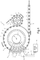
- Figure 1 schematically shows a filling machine (or “filler") 1, configured for filling containers 2, in particular cans, with a filling fluid, in particular a carbonated pourable food product, more particularly beer (it is however again underlined that other types of containers and carbonated liquids may as well be envisaged).
- a filling machine or "filler” 1, configured for filling containers 2, in particular cans, with a filling fluid, in particular a carbonated pourable food product, more particularly beer (it is however again underlined that other types of containers and carbonated liquids may as well be envisaged).
- Filling machine 1 comprises a conveying device, including a rotating conveyor (or carousel) 4, which is mounted to rotate continuously (e.g. anticlockwise in Figure 1 ) about a substantially vertical longitudinal axis A.
- a conveying device including a rotating conveyor (or carousel) 4, which is mounted to rotate continuously (e.g. anticlockwise in Figure 1 ) about a substantially vertical longitudinal axis A.
- the carousel 4 receives a succession of empty containers 2 from an input wheel 7 (or other suitable input conveyor), which is coupled thereto at a first transfer station and is mounted to rotate continuously about a respective vertical longitudinal axis A', parallel to axis A.
- the carousel 4 releases a succession of filled containers 2 to an output conveyor 8 (a linear belt conveyor, as shown in Figure 1 , or another suitable output conveyor), which is coupled thereto at a second transfer station and is configured to transfer the filled containers 2 towards a capping machine configured to cap the same filled containers 2 (or towards another processing machine).
- an output conveyor 8 a linear belt conveyor, as shown in Figure 1 , or another suitable output conveyor
- Filling machine 1 comprises a number of filling units 5, which are equally spaced about axis A, are mounted along a peripheral edge of the carousel 4, and are moved by the same carousel 4 along a path P extending about axis A and through the above transfer stations.
- Each filling unit 5 is designed to receive at least one container 2 to be filled, and to perform, during its rotation along path P, filling operations according to a desired plan, the so called filling "recipe", in order to fill the container 2 with the carbonated product.
- each filling unit 5 includes a main body, for example with a tubular configuration, having a vertical extension along a longitudinal axis that is substantially parallel to axis A of carousel 4, and mechanically coupled to the same carousel 4.
- the main body includes, at a bottom portion thereof, a container receiving part, designed to engage a top portion of a respective container 2 that is to be filled during the filling operations, and generally includes one or more fluidic conduits and flow regulators (here not shown), including valves that are designed to selectively couple the container 2 to one or more feed devices or product tanks (also not shown), of the filling machine 1, via respective filling ducts 6.
- a machine control unit 12 shown schematically, generally including an industrial PLC (Programmable Logic Controller) or any other suitable digital processing unit, for example a computer running a PLC software application, designed to control general operation of the filling machine 1 according to the desired filling recipe.
- a machine control unit 12 shown schematically, generally including an industrial PLC (Programmable Logic Controller) or any other suitable digital processing unit, for example a computer running a PLC software application, designed to control general operation of the filling machine 1 according to the desired filling recipe.
- each filling unit 5 is provided with its own intelligence, i.e. with a respective local control unit 12' (shown schematically), e.g. a processor or similar computing unit, programmed to manage the filling operations of the same filling unit 5 according to the recipe and operatively coupled to the machine control unit 12.
- a respective local control unit 12' shown schematically, e.g. a processor or similar computing unit, programmed to manage the filling operations of the same filling unit 5 according to the recipe and operatively coupled to the machine control unit 12.
- Local control units 12' are communicatively coupled to the machine control unit 12 of the filling machine 1, e.g. via a data communication bus 14, so as to receive control signals from the machine control unit 12 and provide feedback signals to the same machine control unit 12, while filling operations are performed.
- Data communication bus 14 may be a real-time bus, in particular an Ethernet-based real-time communication bus, such as the Powerlink bus, Ethercat, Ethernet Realtime, or Profinet, or any other bus capable to offer data communication capability, even not in real time (e.g. a RS-485 bus).
- Local control units 12' may be coupled to the machine control unit 12 according to a master/slave operating relation (the machine control unit 12 acting as "master” and the local control units 12' acting as "slaves").
- the machine control unit 12 may moreover be coupled to a central supervising unit (here not shown), including a respective PLC or any other suitable computing and processing unit, e.g. located remotely with respect to the filling machine 1, via a cabled or remote wireless link; central supervising unit may supervise and manage operation of various processing machines in a same processing plant, in addition to filling machine 1 (e.g. a capping machine, a labelling machine and so on, all cooperating in processing of the containers 2), and may receive feedback information from the various machines of the processing plant.
- a central supervising unit here not shown
- central supervising unit may supervise and manage operation of various processing machines in a same processing plant, in addition to filling machine 1 (e.g. a capping machine, a labelling machine and so on, all cooperating in processing of the containers 2), and may receive feedback information from the various machines of the processing plant.
- the filling recipe envisages a number n of recipe phases or steps 20, with corresponding operations performed by the flow regulators, valves and actuators of the filling units 5, that are executed in a temporal sequence.
- the recipe phases 20 may include:
- the number and type of the actual recipe phases 20 of the filling recipe may vary, according to the specific needs and requirements; in any case, the filling recipe includes at least one recipe phase of flushing of the container 2, which precedes a recipe phase of actual filling of the same container 2.
- two or more distinct recipe phases of flushing are envisaged (which are subsequent in time and may or may not be consecutive), for example a first flushing recipe phase, followed by a pressurization recipe phase, in turn followed by a second flushing recipe phase.
- a particular aspect of the present solution envisages an increase of duration of at least one flushing phase of the filling recipe, without any further modification of the same filling recipe (which remains therefore optimized for the particular product and operating conditions).
- the increase of the flushing duration is implemented dynamically, i.e. in real-time during the filling operations, while the filling recipe is being executed.
- the increase of the flushing duration allows to further saturate the inside of the container 2 with carbonated dioxide, before the filling operations are performed, thereby opposing and limiting subsequent introduction of oxygen within the same container 2 and allowing to satisfy the oxygen concentration requirements for the filled containers 2 (e.g. in terms of the TPO and/or the quantity of dissolved oxygen).
- the determination of the cause of disturbance envisages assessing that the speed of the carousel 4 is lower than a design (or nominal) rotating speed S N , in particular that an actual speed S ACT of the carousel 4 is lower than a threshold speed S TH , that is lower than (or equal to) the nominal rotating speed S N of the same carousel 4.
- a design (or nominal) rotating speed S N in particular that an actual speed S ACT of the carousel 4 is lower than a threshold speed S TH , that is lower than (or equal to) the nominal rotating speed S N of the same carousel 4.
- the above threshold speed TH may be set equal to 50000 cph.
- the additional duration ⁇ T (that is added to the duration originally envisaged by the filling recipe) is a linear function of this speed difference ⁇ S.
- a time offset Off may be set, e.g. equal to 100 ms, corresponding to a given interval of the speed difference ⁇ S, e.g. equal to 10000 cph: in other words, the value of the additional duration ⁇ T is increased of the time offset Off for every interval of the speed difference ⁇ S.
- the local control unit 12' of each filling unit 5 is configured (having suitable program instructions stored in a non-volatile memory coupled to the corresponding computing unit) to determine the additional duration ⁇ T for the above discussed increase of the flushing duration, upon the occurrence of a disturbance cause leading to a possible increase of the oxygen amount in the filled containers 2.
- local control unit 12' of the filling unit 5 is configured to receive the filling recipe (including all the recipe phases 20) and a start command of the filling operations from the machine control unit 12.
- the same local control unit 12' is configured to determine which is the last flushing phase in the filling recipe and to dynamically increase the duration thereof, e.g. adding an additional duration ⁇ T being a function of the speed difference ⁇ S between the threshold speed S TH and the actual rotating speed S ACT of the carousel 4.
- the machine control unit 12 is configured to determine which is the last flushing phase of the filling recipe and to dynamically increase the duration thereof; the machine control unit 12 is further configured to communicate the filling recipe, with the flushing phase having the suitably increased duration, to the local control unit 12' of the filling units 5, so that they may execute the same filling recipe.
- the proposed solution allows to improve the efficiency of the filling machine 1, without requiring a change of the tilling recipe, except for an increase of duration of the flushing operation (in particular, of a last flushing phase in the filling recipe).
- the present solution allows to avoid undesired increase of the oxygen amount (the dissolved oxygen amount and/or the total package amount) in the filled containers 2, that could cause a degradation of the quality of the filled product, in particular beer.
- the discussed solution allows to modify the filling recipe dynamically during the filling operations, and cope with possible variations of the external conditions (that are not controlled by the filling machine 1), in an automated manner, without requiring intervention by human personnel.
- the discussed solution is configured to dynamically react to the mentioned causes of disturbance that could cause an increase of the oxygen amount in the filled containers 2.
- the dynamic determination of the increased duration of the flushing operation could even be performed by a further processing module, that could be implemented externally to the machine control unit 12 of the filling machine 1 and to the local control units 12', for example by the central supervising unit of the processing plant or by a further, dedicated, processing unit properly arranged at the filling machine 1 or externally thereto.
Landscapes
- Chemical & Material Sciences (AREA)
- Chemical Kinetics & Catalysis (AREA)
- Filling Of Jars Or Cans And Processes For Cleaning And Sealing Jars (AREA)
Claims (15)
- System zum Befüllen von Behältern (2) mit einem kohlensäurehaltigen Produkt durch eine Behälterbefüllungsmaschine (1), umfassend eine Anzahl von Befüllungseinheiten (5), die an einen Rotationsförderer (4) gekoppelt sind, der vorgesehen ist, um sich um eine Rotationsachse (A) zu drehen, und ausgestaltet ist, um Befüllungsoperationen an einem jeweiligen Behälter (2) gemäß einem Befüllungsrezept durchzuführen; wobei das Befüllungsrezept mindestens eine Spülphase zum Spülen des Behälters (2) mit einem Strom aus Kohlendioxid (CO2) umfasst, die einer Befüllungsphase zum Befüllen des Behälters mit dem kohlensäurehaltigen Produkt vorausgeht,
dadurch gekennzeichnet, dass
das System ein Verarbeitungsmodul (12; 12') umfasst, das ausgestaltet ist zum:Ermitteln einer Störungsursache, welche die Befüllungsmaschine (1) beeinflusst, die zu einer Erhöhung der Sauerstoffmenge in den befüllten Behältern (2) führen würde; undin Reaktion auf das Ermitteln der Störungsursache Bewirken eines dynamischen Anstiegs der Dauer der mindestens einen Spülphase des Befüllungsrezepts als Funktion der ermittelten Störung;wobei die Störungsursache eine Reduktion der Rotationsgeschwindigkeit des Rotationsförderers (4) oder ein Anstieg der Sauerstoffkonzentration in einem Produkttank ist. - System nach Anspruch 1, wobei das Verarbeitungsmodul (12, 12') ausgestaltet ist, um die Störungsursache zu ermitteln und den dynamischen Anstieg der Dauer der mindestens einen Spülphase in Echtzeit zu bewirken, während die Befüllungsoperationen durch die Befüllungsmaschine (1) durchgeführt werden.
- System nach Anspruch 1 oder 2, wobei das Befüllungsrezept eine Anzahl von Spülphasen zum Spülen des Behälters (2) mit einem Strom aus Kohlendioxid (CO2) umfasst, die zeitlich aufeinander folgen und der Befüllungsphase zum Befüllen des Behälters (2) mit dem kohlensäurehaltigen Produkt vorausgehen; wobei die mindestens eine Spülphase eine letzte Phase innerhalb der Spülphasen ist.
- System nach einem der vorhergehenden Ansprüche, wobei das System ausgestaltet ist, um den Anstieg der Dauer zu bewirken, bis ermittelt wird, dass die Störungsursache entfernt worden ist oder den Betrieb der Befüllungsmaschine (1) nicht länger beeinflusst.
- System nach einem der vorhergehenden Ansprüche, wobei die Störungsursache eine Reduktion der Rotationsgeschwindigkeit des Rotationsförderers (4) unter eine Schwellengeschwindigkeit (STH) ist, die niedriger als oder gleich einer Nenngeschwindigkeit (SN) des Rotationsförderers (4) ist; und wobei der Anstieg der Dauer eine Funktion der Reduktion der Rotationsgeschwindigkeit ist.
- System nach Anspruch 5, wobei die Dauer der mindestens einen Spülphase um eine Zusatzdauer (ΔT) erhöht wird, die eine lineare Funktion (f) der Geschwindigkeitsdifferenz (ΔS) zwischen der Schwellengeschwindigkeit (STH) und einer tatsächlichen Rotationsgeschwindigkeit (SACT) des Rotationsförderers (4) ist:

- System nach Anspruch 5 oder 6, wobei ein Zeitversatz (Off) festgelegt wird, der einem gegebenen Intervall der Geschwindigkeitsdifferenz (ΔS) entspricht, und eine Zusatzdauer (ΔT) zu der Dauer der mindestens einen Spülphase addiert wird, wobei die Zusatzdauer (ΔT) für jedes Intervall der Geschwindigkeitsdifferenz (ΔS) um den Zeitversatz (Off) erhöht wird.
- System nach einem der vorhergehenden Ansprüche, wobei die Befüllungsmaschine (1) eine Maschinensteuereinheit (12) einschließt und jede der Befüllungseinheiten (5) mit einer jeweiligen lokalen Steuereinheit (12') ausgestattet ist, die an die Maschinensteuereinheit (12) gekoppelt ist, um das Befüllungsrezept zu empfangen; wobei das Verarbeitungsmodul in der lokalen Steuereinheit (12') implementiert wird.
- System nach einem der Ansprüche 1 bis 7, wobei die Befüllungsmaschine (1) eine Maschinensteuereinheit (12) einschließt und jede der Befüllungseinheiten (5) mit einer jeweiligen lokalen Steuereinheit (12') ausgestattet ist, die an die Maschinensteuereinheit (12) gekoppelt ist, um das Befüllungsrezept zu empfangen; wobei das Verarbeitungsmodul in der Maschinensteuereinheit (12) implementiert wird.
- Befüllungsmaschine (1), die mit dem System gemäß einem der vorhergehenden Ansprüche ausgestattet ist.
- Befüllungsmaschine nach Anspruch 10, wobei die Behälter (2) Dosen sind und das kohlensäurehaltige Produkt Bier ist.
- Verfahren zum Befüllen von Behältern (2) mit einem kohlensäurehaltigen Produkt durch eine Behälterbefüllungsmaschine (1), umfassend eine Anzahl von Befüllungseinheiten (5), die an einen Rotationsförderer (4) gekoppelt sind, der vorgesehen ist, um sich um eine Rotationsachse (A) zu drehen, und ausgestaltet ist, um Befüllungsoperationen an einem jeweiligen Behälter (2) gemäß einem Befüllungsrezept durchzuführen; wobei das Befüllungsrezept mindestens eine Spülphase zum Spülen des Behälters (2) mit einem Strom aus Kohlendioxid (CO2) umfasst, der einer Befüllungsphase zum Befüllen des Behälters (2) mit dem kohlensäurehaltigen Produkt vorausgeht, wobei das Verfahren umfasst:Ermitteln einer Störungsursache, welche die Befüllungsmaschine (1) beeinflusst, die zu einer Erhöhung einer Sauerstoffmenge in den gefüllten Behältern (2) führen würde; undin Reaktion auf das Ermitteln der Störungsursache Bewirken eines dynamischen Anstiegs der Dauer der mindestens einen Spülphase des Befüllungsrezepts als Funktion der ermittelten Störung;wobei die Störungsursache eine Reduktion der Rotationsgeschwindigkeit des Rotationsförderers (4) oder ein Anstieg der Sauerstoffkonzentration in einem Produkttank ist.
- Verfahren nach Anspruch 12, wobei das Befüllungsrezept eine Anzahl von Spülphasen zum Spülen des Behälters (2) mit einem Strom aus Kohlendioxid (CO2) umfasst, die zeitlich aufeinander folgen und der Befüllungsphase zum Befüllen des Behälters (2) mit dem kohlensäurehaltigen Produkt vorausgehen; wobei die mindestens eine Spülphase eine letzte Phase innerhalb der Spülphasen ist.
- Verfahren nach Anspruch 12 oder 13, wobei die Störungsursache eine Reduktion der Rotationsgeschwindigkeit des Rotationsförderers (4) unter eine Schwellengeschwindigkeit (STH) ist, die niedriger als oder gleich einer Nenngeschwindigkeit (SN) des Rotationsförderers (4) ist; und wobei der Anstieg der Dauer eine Funktion der Reduktion der Rotationsgeschwindigkeit ist.
- Computerprogrammprodukt, umfassend Anweisungen zum Bewirken, dass das System gemäß einem der Ansprüche 1 bis 11 das Verfahren gemäß einem der Ansprüche 12 bis 14 durchführt.
Priority Applications (2)
| Application Number | Priority Date | Filing Date | Title |
|---|---|---|---|
| EP18306406.2A EP3647257B1 (de) | 2018-10-29 | 2018-10-29 | System und verfahren zum befüllen von behältern mit einem kohlensäurehaltigen produkt, mit verbesserter effizienz |
| PCT/EP2019/077713 WO2020088918A1 (en) | 2018-10-29 | 2019-10-14 | System and method for filling containers with a carbonated product, having improved efficiency |
Applications Claiming Priority (1)
| Application Number | Priority Date | Filing Date | Title |
|---|---|---|---|
| EP18306406.2A EP3647257B1 (de) | 2018-10-29 | 2018-10-29 | System und verfahren zum befüllen von behältern mit einem kohlensäurehaltigen produkt, mit verbesserter effizienz |
Publications (2)
| Publication Number | Publication Date |
|---|---|
| EP3647257A1 EP3647257A1 (de) | 2020-05-06 |
| EP3647257B1 true EP3647257B1 (de) | 2021-04-14 |
Family
ID=64267743
Family Applications (1)
| Application Number | Title | Priority Date | Filing Date |
|---|---|---|---|
| EP18306406.2A Active EP3647257B1 (de) | 2018-10-29 | 2018-10-29 | System und verfahren zum befüllen von behältern mit einem kohlensäurehaltigen produkt, mit verbesserter effizienz |
Country Status (2)
| Country | Link |
|---|---|
| EP (1) | EP3647257B1 (de) |
| WO (1) | WO2020088918A1 (de) |
Families Citing this family (1)
| Publication number | Priority date | Publication date | Assignee | Title |
|---|---|---|---|---|
| CN112125262A (zh) * | 2020-08-21 | 2020-12-25 | 南京禹智智能科技有限公司 | 一种果汁玻璃瓶的全自动灌装设备及其工作方法 |
Family Cites Families (2)
| Publication number | Priority date | Publication date | Assignee | Title |
|---|---|---|---|---|
| DE4429594A1 (de) * | 1994-08-20 | 1996-02-22 | Khs Masch & Anlagenbau Ag | Verfahren zum Abfüllen eines flüssigen Füllgutes in Flaschen oder dgl. Behälter |
| JP4990368B2 (ja) * | 2006-11-29 | 2012-08-01 | シデル ホールディングス アンド テクノロジー エスエー | 充填バルブユニット |
-
2018
- 2018-10-29 EP EP18306406.2A patent/EP3647257B1/de active Active
-
2019
- 2019-10-14 WO PCT/EP2019/077713 patent/WO2020088918A1/en not_active Ceased
Also Published As
| Publication number | Publication date |
|---|---|
| EP3647257A1 (de) | 2020-05-06 |
| WO2020088918A1 (en) | 2020-05-07 |
Similar Documents
| Publication | Publication Date | Title |
|---|---|---|
| US8905226B2 (en) | Container handling arrangement with adjustable handling structures for handling different containers and groups of containers, and a method of adjusting adjustable handling structures for handling different containers and groups of containers | |
| Tomar et al. | PLC and SCADA based industrial automated system | |
| US5713403A (en) | Method and system for filling containers with a liquid filling product, and filling machine and labelling device for use with this method or system | |
| US6119434A (en) | Multi-product packaging machine with bar code reader | |
| US6082418A (en) | Aseptic container filling assembly | |
| EP2038204B1 (de) | Verfahren zur ausfallsicheren steuerung eines füllventils | |
| US20070006939A1 (en) | Beverage bottling plant with a beverage bottle filling machine for filling beverage bottles, and filling elements for the beverage bottle filling machine | |
| US10017370B2 (en) | Machine and method for filling containers | |
| WO2019048051A1 (en) | SYSTEM AND METHOD FOR AUTOMATED SETTING OF CONTAINER FILLING MACHINE | |
| US4467847A (en) | Machine for labeling and/or filling bottles along two paths | |
| EP4326627A2 (de) | Behälterbehandlungsanlage und behälterbehandlungsverfahren zur behandlung von behältern | |
| EP3187948A1 (de) | System und verfahren zur verwaltung der produktqualität in behälterverarbeitungsanlagen | |
| CN115123986A (zh) | 用于将液体产品无菌地装入瓶中的装瓶线和方法 | |
| EP1549547B1 (de) | Verfahren und vorrichtung zum dosieren von flüssigen substanzen in behältern | |
| EP3647257B1 (de) | System und verfahren zum befüllen von behältern mit einem kohlensäurehaltigen produkt, mit verbesserter effizienz | |
| US10870506B2 (en) | Filling system | |
| EP3995916B1 (de) | System und verfahren zur umstellung einer verpackungsanlage für fliessfähige produkte und verfahren zur herstellung einer verpackungsanlage für fliessfähige produkte | |
| CN111533065A (zh) | 用于处理容器的装置 | |
| EP3225561B1 (de) | Behälterbehandlungsmaschine und verfahren zum betrieb solch einer maschine | |
| EP3378828A1 (de) | Behälterfüllmaschine mit verbesserter datenübertragung und speicherfähigkeit | |
| US12179407B2 (en) | Machine block for producing and filling bottles and method for controlling the machine block | |
| EP3668697B1 (de) | System und verfahren zur geschwindigkeitsanpassung in einer kombinierten containerverarbeitungsanlage | |
| JP2580329B2 (ja) | 充填処理装置 | |
| EP3822224A1 (de) | Füllmaschine und verfahren zum befüllen von behältern mit einem fliessfähigen produkt | |
| EP2777830B1 (de) | Verfahren und Vorrichtung zum Reinigen eines Transportsegments |
Legal Events
| Date | Code | Title | Description |
|---|---|---|---|
| PUAI | Public reference made under article 153(3) epc to a published international application that has entered the european phase |
Free format text: ORIGINAL CODE: 0009012 |
|
| STAA | Information on the status of an ep patent application or granted ep patent |
Free format text: STATUS: THE APPLICATION HAS BEEN PUBLISHED |
|
| AK | Designated contracting states |
Kind code of ref document: A1 Designated state(s): AL AT BE BG CH CY CZ DE DK EE ES FI FR GB GR HR HU IE IS IT LI LT LU LV MC MK MT NL NO PL PT RO RS SE SI SK SM TR |
|
| AX | Request for extension of the european patent |
Extension state: BA ME |
|
| STAA | Information on the status of an ep patent application or granted ep patent |
Free format text: STATUS: REQUEST FOR EXAMINATION WAS MADE |
|
| 17P | Request for examination filed |
Effective date: 20200814 |
|
| RBV | Designated contracting states (corrected) |
Designated state(s): AL AT BE BG CH CY CZ DE DK EE ES FI FR GB GR HR HU IE IS IT LI LT LU LV MC MK MT NL NO PL PT RO RS SE SI SK SM TR |
|
| GRAP | Despatch of communication of intention to grant a patent |
Free format text: ORIGINAL CODE: EPIDOSNIGR1 |
|
| STAA | Information on the status of an ep patent application or granted ep patent |
Free format text: STATUS: GRANT OF PATENT IS INTENDED |
|
| GRAS | Grant fee paid |
Free format text: ORIGINAL CODE: EPIDOSNIGR3 |
|
| INTG | Intention to grant announced |
Effective date: 20210210 |
|
| GRAA | (expected) grant |
Free format text: ORIGINAL CODE: 0009210 |
|
| STAA | Information on the status of an ep patent application or granted ep patent |
Free format text: STATUS: THE PATENT HAS BEEN GRANTED |
|
| AK | Designated contracting states |
Kind code of ref document: B1 Designated state(s): AL AT BE BG CH CY CZ DE DK EE ES FI FR GB GR HR HU IE IS IT LI LT LU LV MC MK MT NL NO PL PT RO RS SE SI SK SM TR |
|
| REG | Reference to a national code |
Ref country code: GB Ref legal event code: FG4D |
|
| REG | Reference to a national code |
Ref country code: CH Ref legal event code: EP |
|
| REG | Reference to a national code |
Ref country code: DE Ref legal event code: R096 Ref document number: 602018015491 Country of ref document: DE |
|
| REG | Reference to a national code |
Ref country code: IE Ref legal event code: FG4D |
|
| REG | Reference to a national code |
Ref country code: AT Ref legal event code: REF Ref document number: 1382213 Country of ref document: AT Kind code of ref document: T Effective date: 20210515 |
|
| REG | Reference to a national code |
Ref country code: LT Ref legal event code: MG9D |
|
| REG | Reference to a national code |
Ref country code: AT Ref legal event code: MK05 Ref document number: 1382213 Country of ref document: AT Kind code of ref document: T Effective date: 20210414 |
|
| REG | Reference to a national code |
Ref country code: NL Ref legal event code: MP Effective date: 20210414 |
|
| PG25 | Lapsed in a contracting state [announced via postgrant information from national office to epo] |
Ref country code: FI Free format text: LAPSE BECAUSE OF FAILURE TO SUBMIT A TRANSLATION OF THE DESCRIPTION OR TO PAY THE FEE WITHIN THE PRESCRIBED TIME-LIMIT Effective date: 20210414 Ref country code: LT Free format text: LAPSE BECAUSE OF FAILURE TO SUBMIT A TRANSLATION OF THE DESCRIPTION OR TO PAY THE FEE WITHIN THE PRESCRIBED TIME-LIMIT Effective date: 20210414 Ref country code: HR Free format text: LAPSE BECAUSE OF FAILURE TO SUBMIT A TRANSLATION OF THE DESCRIPTION OR TO PAY THE FEE WITHIN THE PRESCRIBED TIME-LIMIT Effective date: 20210414 Ref country code: BG Free format text: LAPSE BECAUSE OF FAILURE TO SUBMIT A TRANSLATION OF THE DESCRIPTION OR TO PAY THE FEE WITHIN THE PRESCRIBED TIME-LIMIT Effective date: 20210714 Ref country code: AT Free format text: LAPSE BECAUSE OF FAILURE TO SUBMIT A TRANSLATION OF THE DESCRIPTION OR TO PAY THE FEE WITHIN THE PRESCRIBED TIME-LIMIT Effective date: 20210414 Ref country code: NL Free format text: LAPSE BECAUSE OF FAILURE TO SUBMIT A TRANSLATION OF THE DESCRIPTION OR TO PAY THE FEE WITHIN THE PRESCRIBED TIME-LIMIT Effective date: 20210414 |
|
| PG25 | Lapsed in a contracting state [announced via postgrant information from national office to epo] |
Ref country code: RS Free format text: LAPSE BECAUSE OF FAILURE TO SUBMIT A TRANSLATION OF THE DESCRIPTION OR TO PAY THE FEE WITHIN THE PRESCRIBED TIME-LIMIT Effective date: 20210414 Ref country code: SE Free format text: LAPSE BECAUSE OF FAILURE TO SUBMIT A TRANSLATION OF THE DESCRIPTION OR TO PAY THE FEE WITHIN THE PRESCRIBED TIME-LIMIT Effective date: 20210414 Ref country code: PT Free format text: LAPSE BECAUSE OF FAILURE TO SUBMIT A TRANSLATION OF THE DESCRIPTION OR TO PAY THE FEE WITHIN THE PRESCRIBED TIME-LIMIT Effective date: 20210816 Ref country code: NO Free format text: LAPSE BECAUSE OF FAILURE TO SUBMIT A TRANSLATION OF THE DESCRIPTION OR TO PAY THE FEE WITHIN THE PRESCRIBED TIME-LIMIT Effective date: 20210714 Ref country code: LV Free format text: LAPSE BECAUSE OF FAILURE TO SUBMIT A TRANSLATION OF THE DESCRIPTION OR TO PAY THE FEE WITHIN THE PRESCRIBED TIME-LIMIT Effective date: 20210414 Ref country code: PL Free format text: LAPSE BECAUSE OF FAILURE TO SUBMIT A TRANSLATION OF THE DESCRIPTION OR TO PAY THE FEE WITHIN THE PRESCRIBED TIME-LIMIT Effective date: 20210414 Ref country code: IS Free format text: LAPSE BECAUSE OF FAILURE TO SUBMIT A TRANSLATION OF THE DESCRIPTION OR TO PAY THE FEE WITHIN THE PRESCRIBED TIME-LIMIT Effective date: 20210814 Ref country code: GR Free format text: LAPSE BECAUSE OF FAILURE TO SUBMIT A TRANSLATION OF THE DESCRIPTION OR TO PAY THE FEE WITHIN THE PRESCRIBED TIME-LIMIT Effective date: 20210715 |
|
| REG | Reference to a national code |
Ref country code: DE Ref legal event code: R097 Ref document number: 602018015491 Country of ref document: DE |
|
| PG25 | Lapsed in a contracting state [announced via postgrant information from national office to epo] |
Ref country code: SM Free format text: LAPSE BECAUSE OF FAILURE TO SUBMIT A TRANSLATION OF THE DESCRIPTION OR TO PAY THE FEE WITHIN THE PRESCRIBED TIME-LIMIT Effective date: 20210414 Ref country code: SK Free format text: LAPSE BECAUSE OF FAILURE TO SUBMIT A TRANSLATION OF THE DESCRIPTION OR TO PAY THE FEE WITHIN THE PRESCRIBED TIME-LIMIT Effective date: 20210414 Ref country code: EE Free format text: LAPSE BECAUSE OF FAILURE TO SUBMIT A TRANSLATION OF THE DESCRIPTION OR TO PAY THE FEE WITHIN THE PRESCRIBED TIME-LIMIT Effective date: 20210414 Ref country code: ES Free format text: LAPSE BECAUSE OF FAILURE TO SUBMIT A TRANSLATION OF THE DESCRIPTION OR TO PAY THE FEE WITHIN THE PRESCRIBED TIME-LIMIT Effective date: 20210414 Ref country code: CZ Free format text: LAPSE BECAUSE OF FAILURE TO SUBMIT A TRANSLATION OF THE DESCRIPTION OR TO PAY THE FEE WITHIN THE PRESCRIBED TIME-LIMIT Effective date: 20210414 Ref country code: DK Free format text: LAPSE BECAUSE OF FAILURE TO SUBMIT A TRANSLATION OF THE DESCRIPTION OR TO PAY THE FEE WITHIN THE PRESCRIBED TIME-LIMIT Effective date: 20210414 Ref country code: RO Free format text: LAPSE BECAUSE OF FAILURE TO SUBMIT A TRANSLATION OF THE DESCRIPTION OR TO PAY THE FEE WITHIN THE PRESCRIBED TIME-LIMIT Effective date: 20210414 |
|
| PLBE | No opposition filed within time limit |
Free format text: ORIGINAL CODE: 0009261 |
|
| STAA | Information on the status of an ep patent application or granted ep patent |
Free format text: STATUS: NO OPPOSITION FILED WITHIN TIME LIMIT |
|
| 26N | No opposition filed |
Effective date: 20220117 |
|
| REG | Reference to a national code |
Ref country code: CH Ref legal event code: PL |
|
| PG25 | Lapsed in a contracting state [announced via postgrant information from national office to epo] |
Ref country code: IS Free format text: LAPSE BECAUSE OF FAILURE TO SUBMIT A TRANSLATION OF THE DESCRIPTION OR TO PAY THE FEE WITHIN THE PRESCRIBED TIME-LIMIT Effective date: 20210814 Ref country code: AL Free format text: LAPSE BECAUSE OF FAILURE TO SUBMIT A TRANSLATION OF THE DESCRIPTION OR TO PAY THE FEE WITHIN THE PRESCRIBED TIME-LIMIT Effective date: 20210414 |
|
| REG | Reference to a national code |
Ref country code: BE Ref legal event code: MM Effective date: 20211031 |
|
| PG25 | Lapsed in a contracting state [announced via postgrant information from national office to epo] |
Ref country code: MC Free format text: LAPSE BECAUSE OF FAILURE TO SUBMIT A TRANSLATION OF THE DESCRIPTION OR TO PAY THE FEE WITHIN THE PRESCRIBED TIME-LIMIT Effective date: 20210414 |
|
| PG25 | Lapsed in a contracting state [announced via postgrant information from national office to epo] |
Ref country code: LU Free format text: LAPSE BECAUSE OF NON-PAYMENT OF DUE FEES Effective date: 20211029 Ref country code: BE Free format text: LAPSE BECAUSE OF NON-PAYMENT OF DUE FEES Effective date: 20211031 |
|
| PG25 | Lapsed in a contracting state [announced via postgrant information from national office to epo] |
Ref country code: LI Free format text: LAPSE BECAUSE OF NON-PAYMENT OF DUE FEES Effective date: 20211031 Ref country code: CH Free format text: LAPSE BECAUSE OF NON-PAYMENT OF DUE FEES Effective date: 20211031 |
|
| PG25 | Lapsed in a contracting state [announced via postgrant information from national office to epo] |
Ref country code: IE Free format text: LAPSE BECAUSE OF NON-PAYMENT OF DUE FEES Effective date: 20211029 |
|
| P01 | Opt-out of the competence of the unified patent court (upc) registered |
Effective date: 20230306 |
|
| GBPC | Gb: european patent ceased through non-payment of renewal fee |
Effective date: 20221029 |
|
| PG25 | Lapsed in a contracting state [announced via postgrant information from national office to epo] |
Ref country code: CY Free format text: LAPSE BECAUSE OF FAILURE TO SUBMIT A TRANSLATION OF THE DESCRIPTION OR TO PAY THE FEE WITHIN THE PRESCRIBED TIME-LIMIT Effective date: 20210414 |
|
| PG25 | Lapsed in a contracting state [announced via postgrant information from national office to epo] |
Ref country code: HU Free format text: LAPSE BECAUSE OF FAILURE TO SUBMIT A TRANSLATION OF THE DESCRIPTION OR TO PAY THE FEE WITHIN THE PRESCRIBED TIME-LIMIT; INVALID AB INITIO Effective date: 20181029 |
|
| PG25 | Lapsed in a contracting state [announced via postgrant information from national office to epo] |
Ref country code: GB Free format text: LAPSE BECAUSE OF NON-PAYMENT OF DUE FEES Effective date: 20221029 |
|
| PG25 | Lapsed in a contracting state [announced via postgrant information from national office to epo] |
Ref country code: MK Free format text: LAPSE BECAUSE OF FAILURE TO SUBMIT A TRANSLATION OF THE DESCRIPTION OR TO PAY THE FEE WITHIN THE PRESCRIBED TIME-LIMIT Effective date: 20210414 |
|
| PG25 | Lapsed in a contracting state [announced via postgrant information from national office to epo] |
Ref country code: TR Free format text: LAPSE BECAUSE OF FAILURE TO SUBMIT A TRANSLATION OF THE DESCRIPTION OR TO PAY THE FEE WITHIN THE PRESCRIBED TIME-LIMIT Effective date: 20210414 |
|
| PG25 | Lapsed in a contracting state [announced via postgrant information from national office to epo] |
Ref country code: MT Free format text: LAPSE BECAUSE OF FAILURE TO SUBMIT A TRANSLATION OF THE DESCRIPTION OR TO PAY THE FEE WITHIN THE PRESCRIBED TIME-LIMIT Effective date: 20210414 |
|
| PGFP | Annual fee paid to national office [announced via postgrant information from national office to epo] |
Ref country code: IT Payment date: 20250923 Year of fee payment: 8 |
|
| PGFP | Annual fee paid to national office [announced via postgrant information from national office to epo] |
Ref country code: FR Payment date: 20250924 Year of fee payment: 8 |
|
| PGFP | Annual fee paid to national office [announced via postgrant information from national office to epo] |
Ref country code: DE Payment date: 20250923 Year of fee payment: 8 |