EP3647585B1 - Hydroelektrische turbinenkomponente mit erhöhter lebensdauer und verfahren zu ihrer herstellung - Google Patents
Hydroelektrische turbinenkomponente mit erhöhter lebensdauer und verfahren zu ihrer herstellung Download PDFInfo
- Publication number
- EP3647585B1 EP3647585B1 EP19205675.2A EP19205675A EP3647585B1 EP 3647585 B1 EP3647585 B1 EP 3647585B1 EP 19205675 A EP19205675 A EP 19205675A EP 3647585 B1 EP3647585 B1 EP 3647585B1
- Authority
- EP
- European Patent Office
- Prior art keywords
- coating
- hydro
- tip portion
- side portions
- turbine component
- Prior art date
- Legal status (The legal status is an assumption and is not a legal conclusion. Google has not performed a legal analysis and makes no representation as to the accuracy of the status listed.)
- Active
Links
Images


Classifications
-
- F—MECHANICAL ENGINEERING; LIGHTING; HEATING; WEAPONS; BLASTING
- F03—MACHINES OR ENGINES FOR LIQUIDS; WIND, SPRING, OR WEIGHT MOTORS; PRODUCING MECHANICAL POWER OR A REACTIVE PROPULSIVE THRUST, NOT OTHERWISE PROVIDED FOR
- F03B—MACHINES OR ENGINES FOR LIQUIDS
- F03B11/00—Parts or details not provided for in, or of interest apart from, the preceding groups, e.g. wear-protection couplings, between turbine and generator
-
- C—CHEMISTRY; METALLURGY
- C23—COATING METALLIC MATERIAL; COATING MATERIAL WITH METALLIC MATERIAL; CHEMICAL SURFACE TREATMENT; DIFFUSION TREATMENT OF METALLIC MATERIAL; COATING BY VACUUM EVAPORATION, BY SPUTTERING, BY ION IMPLANTATION OR BY CHEMICAL VAPOUR DEPOSITION, IN GENERAL; INHIBITING CORROSION OF METALLIC MATERIAL OR INCRUSTATION IN GENERAL
- C23C—COATING METALLIC MATERIAL; COATING MATERIAL WITH METALLIC MATERIAL; SURFACE TREATMENT OF METALLIC MATERIAL BY DIFFUSION INTO THE SURFACE, BY CHEMICAL CONVERSION OR SUBSTITUTION; COATING BY VACUUM EVAPORATION, BY SPUTTERING, BY ION IMPLANTATION OR BY CHEMICAL VAPOUR DEPOSITION, IN GENERAL
- C23C4/00—Coating by spraying the coating material in the molten state, e.g. by flame, plasma or electric discharge
- C23C4/04—Coating by spraying the coating material in the molten state, e.g. by flame, plasma or electric discharge characterised by the coating material
- C23C4/06—Metallic material
-
- C—CHEMISTRY; METALLURGY
- C23—COATING METALLIC MATERIAL; COATING MATERIAL WITH METALLIC MATERIAL; CHEMICAL SURFACE TREATMENT; DIFFUSION TREATMENT OF METALLIC MATERIAL; COATING BY VACUUM EVAPORATION, BY SPUTTERING, BY ION IMPLANTATION OR BY CHEMICAL VAPOUR DEPOSITION, IN GENERAL; INHIBITING CORROSION OF METALLIC MATERIAL OR INCRUSTATION IN GENERAL
- C23C—COATING METALLIC MATERIAL; COATING MATERIAL WITH METALLIC MATERIAL; SURFACE TREATMENT OF METALLIC MATERIAL BY DIFFUSION INTO THE SURFACE, BY CHEMICAL CONVERSION OR SUBSTITUTION; COATING BY VACUUM EVAPORATION, BY SPUTTERING, BY ION IMPLANTATION OR BY CHEMICAL VAPOUR DEPOSITION, IN GENERAL
- C23C4/00—Coating by spraying the coating material in the molten state, e.g. by flame, plasma or electric discharge
- C23C4/12—Coating by spraying the coating material in the molten state, e.g. by flame, plasma or electric discharge characterised by the method of spraying
- C23C4/129—Flame spraying
-
- F—MECHANICAL ENGINEERING; LIGHTING; HEATING; WEAPONS; BLASTING
- F03—MACHINES OR ENGINES FOR LIQUIDS; WIND, SPRING, OR WEIGHT MOTORS; PRODUCING MECHANICAL POWER OR A REACTIVE PROPULSIVE THRUST, NOT OTHERWISE PROVIDED FOR
- F03B—MACHINES OR ENGINES FOR LIQUIDS
- F03B1/00—Engines of impulse type, i.e. turbines with jets of high-velocity liquid impinging on blades or like rotors, e.g. Pelton wheels; Parts or details peculiar thereto
- F03B1/02—Buckets; Bucket-carrying rotors
-
- F—MECHANICAL ENGINEERING; LIGHTING; HEATING; WEAPONS; BLASTING
- F03—MACHINES OR ENGINES FOR LIQUIDS; WIND, SPRING, OR WEIGHT MOTORS; PRODUCING MECHANICAL POWER OR A REACTIVE PROPULSIVE THRUST, NOT OTHERWISE PROVIDED FOR
- F03B—MACHINES OR ENGINES FOR LIQUIDS
- F03B1/00—Engines of impulse type, i.e. turbines with jets of high-velocity liquid impinging on blades or like rotors, e.g. Pelton wheels; Parts or details peculiar thereto
- F03B1/04—Nozzles; Nozzle-carrying members
-
- F—MECHANICAL ENGINEERING; LIGHTING; HEATING; WEAPONS; BLASTING
- F03—MACHINES OR ENGINES FOR LIQUIDS; WIND, SPRING, OR WEIGHT MOTORS; PRODUCING MECHANICAL POWER OR A REACTIVE PROPULSIVE THRUST, NOT OTHERWISE PROVIDED FOR
- F03B—MACHINES OR ENGINES FOR LIQUIDS
- F03B3/00—Machines or engines of reaction type; Parts or details peculiar thereto
- F03B3/12—Blades; Blade-carrying rotors
- F03B3/121—Blades, their form or construction
-
- F—MECHANICAL ENGINEERING; LIGHTING; HEATING; WEAPONS; BLASTING
- F03—MACHINES OR ENGINES FOR LIQUIDS; WIND, SPRING, OR WEIGHT MOTORS; PRODUCING MECHANICAL POWER OR A REACTIVE PROPULSIVE THRUST, NOT OTHERWISE PROVIDED FOR
- F03B—MACHINES OR ENGINES FOR LIQUIDS
- F03B3/00—Machines or engines of reaction type; Parts or details peculiar thereto
- F03B3/12—Blades; Blade-carrying rotors
- F03B3/121—Blades, their form or construction
- F03B3/123—Blades, their form or construction specially designed as adjustable blades, e.g. for Kaplan-type turbines
-
- F—MECHANICAL ENGINEERING; LIGHTING; HEATING; WEAPONS; BLASTING
- F03—MACHINES OR ENGINES FOR LIQUIDS; WIND, SPRING, OR WEIGHT MOTORS; PRODUCING MECHANICAL POWER OR A REACTIVE PROPULSIVE THRUST, NOT OTHERWISE PROVIDED FOR
- F03B—MACHINES OR ENGINES FOR LIQUIDS
- F03B3/00—Machines or engines of reaction type; Parts or details peculiar thereto
- F03B3/16—Stators
- F03B3/18—Stator blades; Guide conduits or vanes, e.g. adjustable
-
- F—MECHANICAL ENGINEERING; LIGHTING; HEATING; WEAPONS; BLASTING
- F05—INDEXING SCHEMES RELATING TO ENGINES OR PUMPS IN VARIOUS SUBCLASSES OF CLASSES F01-F04
- F05B—INDEXING SCHEME RELATING TO WIND, SPRING, WEIGHT, INERTIA OR LIKE MOTORS, TO MACHINES OR ENGINES FOR LIQUIDS COVERED BY SUBCLASSES F03B, F03D AND F03G
- F05B2230/00—Manufacture
- F05B2230/30—Manufacture with deposition of material
- F05B2230/31—Layer deposition
- F05B2230/311—Layer deposition by torch or flame spray
-
- F—MECHANICAL ENGINEERING; LIGHTING; HEATING; WEAPONS; BLASTING
- F05—INDEXING SCHEMES RELATING TO ENGINES OR PUMPS IN VARIOUS SUBCLASSES OF CLASSES F01-F04
- F05B—INDEXING SCHEME RELATING TO WIND, SPRING, WEIGHT, INERTIA OR LIKE MOTORS, TO MACHINES OR ENGINES FOR LIQUIDS COVERED BY SUBCLASSES F03B, F03D AND F03G
- F05B2230/00—Manufacture
- F05B2230/90—Coating; Surface treatment
-
- F—MECHANICAL ENGINEERING; LIGHTING; HEATING; WEAPONS; BLASTING
- F05—INDEXING SCHEMES RELATING TO ENGINES OR PUMPS IN VARIOUS SUBCLASSES OF CLASSES F01-F04
- F05B—INDEXING SCHEME RELATING TO WIND, SPRING, WEIGHT, INERTIA OR LIKE MOTORS, TO MACHINES OR ENGINES FOR LIQUIDS COVERED BY SUBCLASSES F03B, F03D AND F03G
- F05B2280/00—Materials; Properties thereof
- F05B2280/60—Properties or characteristics given to material by treatment or manufacturing
- F05B2280/6011—Coating
-
- Y—GENERAL TAGGING OF NEW TECHNOLOGICAL DEVELOPMENTS; GENERAL TAGGING OF CROSS-SECTIONAL TECHNOLOGIES SPANNING OVER SEVERAL SECTIONS OF THE IPC; TECHNICAL SUBJECTS COVERED BY FORMER USPC CROSS-REFERENCE ART COLLECTIONS [XRACs] AND DIGESTS
- Y02—TECHNOLOGIES OR APPLICATIONS FOR MITIGATION OR ADAPTATION AGAINST CLIMATE CHANGE
- Y02E—REDUCTION OF GREENHOUSE GAS [GHG] EMISSIONS, RELATED TO ENERGY GENERATION, TRANSMISSION OR DISTRIBUTION
- Y02E10/00—Energy generation through renewable energy sources
- Y02E10/20—Hydro energy
-
- Y—GENERAL TAGGING OF NEW TECHNOLOGICAL DEVELOPMENTS; GENERAL TAGGING OF CROSS-SECTIONAL TECHNOLOGIES SPANNING OVER SEVERAL SECTIONS OF THE IPC; TECHNICAL SUBJECTS COVERED BY FORMER USPC CROSS-REFERENCE ART COLLECTIONS [XRACs] AND DIGESTS
- Y02—TECHNOLOGIES OR APPLICATIONS FOR MITIGATION OR ADAPTATION AGAINST CLIMATE CHANGE
- Y02P—CLIMATE CHANGE MITIGATION TECHNOLOGIES IN THE PRODUCTION OR PROCESSING OF GOODS
- Y02P70/00—Climate change mitigation technologies in the production process for final industrial or consumer products
- Y02P70/50—Manufacturing or production processes characterised by the final manufactured product
Definitions
- the present invention generally relates to a hydro-electric turbine component having enhanced life span and a method for forming the component. Specifically, this invention relates to a hydro-electric turbine component having a coated wedge-shaped substrate and a method for coating the wedge-shaped substrate.
- hydro-electric turbine components such as martensitic stainless steels do not have adequate erosion resistance under these conditions.
- hydro-electric turbine components when exposed to sediment in the rivers that exceed 1 kilogram of sediment per cubic meter of water have been found to undergo significant erosion. This problem can be particularly severe in Asia, South America, and Alps region, where the sediment content during the rainy season can exceed 5 kilograms per cubic meter of water. The severe erosion results in damages of turbine components causing frequent maintenance related shutdowns, loss of operating efficiencies, and need to replace various components on a regular basis.
- various anti-erosion coatings have been developed to mitigate erosion or to prolong life of the components.
- Current erosion resistant coatings are usually applied by thermal spray processes, such as air plasma spray (APS), and high velocity oxy-fuel (HVOF).
- thermal spray processes such as air plasma spray (APS), and high velocity oxy-fuel (HVOF).
- APS air plasma spray
- HVOF high velocity oxy-fuel
- One limitation to current thermal spray processes is the limited coating thicknesses available due to high residual stress that results as thickness is increased by these methods. As a result, the final coating is relatively thin, typically lesser than 500 microns and fails to provide prolonged protection to the turbine component.
- Other limitations of these thermal spray processes are the oxidation and decomposition of the powder feed or wire feed stock during the coating process that form the anti-erosion coating, which can affect the overall quality of the finished coating.
- spray processes such as plasma spray, wire spray, and HVOF are currently used for coating turbine components. These processes generally leave the resulting coating with relatively high porosity, high oxide levels, and/or tend to decarburize primary carbides, if present in the coating. All these factors have significant deleterious effect at reducing erosion resistance of the coatings, in addition to providing low thickness of the erosion coating layers.
- a hydro-electric turbine component according to the invention is disclosed in independent claim 1; a method for coating a wedge-shaped substrate of a hydro-electric turbine component is disclosed in independent claim 10.
- a hydro-electric turbine component includes a wedge-shaped substrate having a tip portion and at least two side portions.
- An erosion resistant coating is disposed on the wedge-shaped substrate.
- the erosion resistant coating disposed at the tip portion is at least 2 times thicker than the erosion resistant coating disposed at the side portions.
- the erosion resistant coating has at least 99.5 percentage density.
- a method for coating a wedge-shaped substrate of a hydro-electric turbine component includes a tip portion and at least two side portions.
- the method includes the steps of coating the tip portion of the substrate by a high velocity air fuel process and then coating the side portions by the high velocity air fuel process.
- the method forms an erosion resistant coating on both the tip portion and the side portions such that the coating at the tip portion is at least 2 times thicker than the coating at the side portions.
- the hydro- electric turbine component in a hydro-electric turbine component or a method according to preferred embodiments of the invention, the hydro- electric turbine component:
- the erosion resistant coating may comprise a metal matrix composite comprising a cobalt chromium matrix.
- the wedge-shaped substrate may comprise a splitter of one of a Pelton bucket, a W-cutout of the Pelton bucket, a Pelton needle, a seat ring, a guide vane of Francis, Kaplan, Bulb, or pump turbine, a runner blade of Francis, Kaplan, Bulb, or pump turbine, or combinations thereof.
- the erosion resistant coating can be crack-free and comprise less than 0.5 percentage oxide content and greater than 1250 HV0.3 hardness.
- a high velocity air fuel (HVAF) process is employed for depositing erosion resistant coatings onto a component surface.
- the HVAF process is a material deposition process in which erosion resistant coatings are applied by exposing a substrate to a high-velocity jet of erosion resistant material powder at a velocity greater than 800 m/s.
- the erosion resistant material powder is accelerated and heated by a supersonic jet of low-temperature "air-fuel gas” combustion products.
- the HVAF spraying process deposits an extremely dense (minimal porosity) and substantially non-oxidized coating.
- the HVAF process utilizes a fuel such as kerosene, propane, propylene, low pressure gas (LPG), compressed natural gas (CNG), or the like, that is combusted with air as opposed to oxygen used in the HVOF process. Since the HVAF process ensures a greater particle velocity and a lower particle temperature, the coatings produced thereby have lower levels of oxidation and decarburization and lower residual stresses as compared to the coatings deposited by the HVOF process.
- a fuel such as kerosene, propane, propylene, low pressure gas (LPG), compressed natural gas (CNG), or the like
- the particles that form the coating are heated and imparted with high kinetic energy due to the flame velocity.
- the particles are propelled toward a substrate that is to be coated and form a coating upon impact with the surface of the substrate.
- the high velocity and lower temperatures employed in the HVAF process enable formation of thick and dense coatings due to the low residual stresses associated with the process, thereby providing improved life of coatings in erosion prone environments.
- the HVAF process is advantageously used to impart erosion resistance to portions of components of the hydro-electric turbine components that are amenable to line of sight thermally sprayed coating processes. Thicknesses in excess of 500 micrometers ( ⁇ m) have been obtained, and these coatings advantageously exhibit low levels of oxidation, low levels of decarburization and low residual stress.
- the HVAF process is advantageously utilized to produce coatings having hard particulates embedded in metallic binder matrix.
- the term "hard particulates" generally refers to materials having a Mohs hardness greater than 7. In some embodiments, the hard particulates have Mohs hardness greater than 8. In certain embodiments, the Mohs hardness of the hard particulates may be greater than 9.
- the hard particulates may include metallic oxides, metallic borides, diamond, or nitrides or borides of a metal, silicon, or boron.
- diamond is intended to include particles that substantially possess the hardness of the diamond molecular structure without necessarily possessing the corresponding molecular structure and is intended to include all forms of diamond particles including powders, flakes, and the like.
- the metallic binder may include metal or metal alloys, which in turn may also further include some non-metallic components such as, for example, ceramics, intermetallic phases, or intermediate phases.
- the metallic binder includes ferrous alloys, nickel-based alloys, cobalt-based alloys, or combinations thereof.
- coating of hard particulates embedded in metallic binder matrix achieved by the HVAF process has limited dissolution of the hard phase, low residual stresses, and desired high thickness.
- the coating substrate design, coating materials, coating process parameters, and method are designed to obtain crack-free, tough, less-oxide content, less carburized, and dense erosion resistant coatings on the hydro-electric turbine component substrates without resulting in spallation or debonding of the coating.
- the combination of high primary hard phase content and high thickness makes HVAF coatings highly suitable for erosion resistance applications in hydro-electric turbines.
- FIG. 1 illustrates a hydro-electric turbine component 100 in the form of a Pelton bucket.
- the Pelton bucket is used as a part of a Pelton wheel runner employed in a hydro-electric turbine.
- Various parts of the Pelton bucket may undergo erosion during operation of the hydro-electric turbine.
- Splitter 110 and W-cutout areas 120 marked in FIG. 1 are the sharp edges of the Pelton bucket and are considered as primary erosion areas in the Pelton bucket.
- the interior walls 130 of the Pelton bucket are the secondary areas of erosion in the Pelton bucket and are relatively less prone to the erosion in comparison to the primary erosion areas. Primary erosion leads to significant damage, which in turn imparts visibly noticeable changes in hydraulic profile of the splitter 110 and W-cutout areas 120.
- the coating method and the coating profile can be advantageously used for other hydro-electric turbine components that have wedge-shaped body parts and are prone to erosion.
- Non-limiting examples of the other hydro-electric turbine components include Pelton needles, seat rings, guide vanes, and runner blades of various turbines such as Francis turbines, Kaplan turbines, Bulb turbines, or pump turbines.
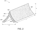
- FIG. 2 illustrates a coated wedge-shaped substrate 200 having a length 1, width w, and height h.
- the coated wedge-shaped substrate 200 may be a part of any of the hydro-electric turbine components noted earlier.
- an erosion resistant coating 250 is disposed over the wedge-shaped substrate 210.
- the wedge-shaped substrate 210 has a tip 220 and at least two sides 230 and 240.
- the tip 220 is relatively more erosion prone region of the wedge-shaped substrate 210 than the sides 230 and 240, in most of the hydro-electric turbine components.
- the hydro-electric turbine component 100 in the form of Pelton bucket illustrated in FIG. 1 includes the coated wedge-shaped substrate 200 having the erosion resistant coating 250 at the tip 220 and at both the sides 230 and 240.
- the coating 250 covers the tip 220 and sides 230, 240 of the wedge-shaped substrate 210.
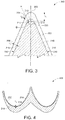
- FIG. 3 provides a cross-sectional view 300 of a portion of the coated wedge-shaped substrate 200 of FIG. 2 and illustrates the coating profile on the wedge-shaped substrate 210, according to some embodiments of this specification.
- the wedge-shaped substrate 210 has a tip portion 212 including the tip 220.
- the tip 220 may be the inflection point of the substrate 210 at the tip portion 212.
- An erosion resistant coating (henceforth "coating", for brevity) 250 is disposed on the wedge-shaped substrate 210 at the tip portion 212 and on both the sides of the tip 220. Therefore, at least one side portion 216 at each of the sides 230 and 240 is coated with the coating 250 resulting in at least two coated side portions 216.
- a thickness of the disposed coating 250 may be designed based on expected severity of erosion damage and the desired erosion protection at a particular portion. Consequently, in locations exposed to water flow at high angles of incidence such as those near to 90 degrees incidence angle, or at high levels of flux of water and sand, the thickness of the coating 250 may be maintained at a greater value than at the locations that are exposed to water flow at low angles of incidence to provide better protection for such locations in the wedge-shaped substrate 210.
- the thickness of the coating 250 at a given location is measured as the perpendicular height of the coating 250 at that location on the surface of the wedge-shaped substrate 210.
- a thickness t 1 of the coating 250 at the tip portion 212 of the wedge-shaped substrate 210 is the perpendicular distance between the tip portion 212 of the substrate to the tip portion of the coating 250.
- a thickness t 1 of the coating 250 at the tip 220 of the wedge-shaped substrate is the perpendicular distance between the tip 220 of the substrate to the tip 252 of the coating 250 along the height h (shown in FIG. 2 ).
- thickness t 3 of the coating 250 at a side portion 216 of the wedge-shaped substrate 210 is the perpendicular distance between the side portion 216 of the substrate to the side portion 256 of the coating 250 in a direction perpendicular to the substrate at the point 216.
- a thickness of the coating 250 disposed at the tip portion 212 is higher than a thickness of the coating disposed at the side portions 216. Further, the thickness t 1 of the coating 250 disposed at the tip portion 212 is at least 2 times than the thickness t 3 of the coating 250 disposed at the side portions 216. In certain embodiments, the thickness t 1 of the coating 250 disposed at the tip portion 212 is at least 3 times thicker than the thickness t 3 of the coating 250 disposed at the side portions 216.
- the coating 250 is applied on an outer surface of the wedge-shaped substrate 210 using a HVAF process. The HVAF process enables a high-dense coating having a density of at least 99.5 percentage (%).
- the coating 250 is crack-free and an oxide content, if present, is less than 0.5% of total volume of the coating 250. In some embodiments, an oxide content in the coating 250 is less than 0.4% of total volume of the coating 250. A hardness of the coating 250 is greater than 1250 HV0.3. In some embodiments, the coating 250 is impact resistant to sediment particles travelling at velocities greater than 90 meters per second. The sediment particles may include some stones and pebbles of average size in a range from less than a millimeter to 10 millimeters in the water jet that impinges on the hydro-electric turbine component 100 such as the Pelton bucket.
- the thickness t 1 of the coating 250 disposed at the tip portion 212 is in a range from 1 millimeter (mm) to 3 mm. In certain embodiments, the thickness t 1 of the coating 250 at the tip portion 212 is in a range from 1.5 mm and 3 mm. In some embodiments, the thickness t 3 of the coating 250 disposed at the side portions 216 is in a range from 0.3 mm to 1 mm. Even though greater thickness of the coating 250 at the side portions 230, 240 is achievable, the coating thickness in a range from 0.3 mm to 1 mm may be sufficient to provide the required erosion protection for the side portions 216 of a wedge-shaped substrate, such as the substrate 210.
- the wedge-shaped substrate may be a Pelton bucket splitter.
- Some other hydroturbine components may require a thick coating on the edges and/or sides of substrates having various geometry.
- substrates such as runners and the guide vanes for Francis-type turbines may have thick coatings at the side portions and the thickness of the coatings may be greater than 1 mm.
- thickness of coatings on the side portions may be in a range from about 1 mm to about 3 mm.
- the side portions are the portions of hydraulic water path without any tip.
- the wedge-shaped substrate 210 further includes an intermediate portion 214 disposed between the tip portion 212 and the side portions 216, on the surface of the wedge-shaped substrate 210 and having the coating 250.
- Thickness t 2 of the coating 250 at the intermediate portion 214 of the wedge-shaped substrate 210 is the linear distance between the intermediate portion 214 of the substrate to the intermediate portion 254 of the coating 250 in a direction perpendicular to the substrate at the point 214.
- the thickness t 2 of the coating 250 at the intermediate portion 214 tapers from the thickness t 1 of the coating 250 at the tip portion 212 to the thickness t 3 of the coating 250 at the side portions 216.
- the thickness t 2 of the coating 250 on the intermediate portion 214 is designed such that there is a gradual decrease in thickness of the coating 250 from the tip portion 212 to the side portions 216 along the sides 230, 240 (shown in FIG. 2 ) of the wedge-shaped substrate 210 without formation of any significant steps in the coating 250.
- the tapering of thickness in the intermediate portion 214 is designed to provide a crack-free and non-delaminated coating 250 on the wedge-shaped substrate 210.
- the thickness t 2 of the coating 250 at the intermediate portion 214 may vary in a range from 0.3 mm to 3 mm, with an increased thickness of the coating 250 with increased height h in the wedge-shaped substrate 210.
- the hydro-electric turbine component 100 may further include the erosion resistant coating 250 in a base portion 218 of the hydro-electric turbine component, as shown in FIG. 4 .
- Thickness t 4 of the coating 250 at the base portion 218 of the wedge-shaped substrate 210 is the perpendicular distance between the base portion 218 of the substrate to the base portion 258 of the coating 250 in a direction perpendicular to the substrate at the point 218.
- the thickness t 4 of the coating 250 at the base portion 218 may be equal to or less than the thickness t 3 of the coating 250 at the side portions 216 (shown in FIG. 3 ).
- a thickness t 4 of the coating 250 at the base portion 218 is in a range from 0.1 mm to 0.3 mm.
- the coating 250 of the side portions 216 and the base portion 218 have a tapering thickness between the coating in the side portions 216 and the base portion 218.
- the thickness of the coating 250 at the tip portion 212, intermediate portions 214, side portions 216, and base portion 218 may have slight variation from one point to another point in the respective portions. Such variation may be less than 10% of the average thickness in the respective portions.
- the tip portion 212 of the wedge-shaped substrate 210 has a curvature that is defined by a radius of curvature R, at the tip portion 212.
- the radius of curvature R defines hydraulic profile for impinging water on the wedge-shaped substrate 210 during operation of the hydro-electric turbine component.
- a smaller radius of curvature R indicating a sharp edge of the tip portion 212 ensures better level of efficiency of operation of the hydro-electric turbine component 100.
- a tip portion 212 of the wedge-shaped splitter has a narrow radius of curvature that aids in efficiently splitting an impinging water jet on the hydro-electric turbine component 100.
- Radius of curvature R of the tip portion 212 influences property of the coating 250 formed on the substrate. For example, a smaller radius of curvature R of the tip portion 212 may lead to a smaller angle ⁇ of the substrate ( FIG. 3 ) and a coating 250 applied at the tip portion 212 may experience greater residual stress compared to a coating 250 applied on a tip portion 212 that has a greater radius of curvature R and greater angle ⁇ .
- the radius of curvature R of the tip portion 212 is in a range from 0.5 mm to 3.0 mm. In certain embodiments, a radius of curvature R of the tip portion 212 is in a range from 1 mm to 2 mm. In certain other embodiments, a radius of curvature R of the tip portion 212 is less than 1 mm. In some embodiments, an incident angle ⁇ at the tip portion is in a range from 15° to 55°. In hydro-electric turbine component 100, water also strikes on front W-cutout 120 ( FIG.
- W-cutout 120 has tip portion and side portions, hence all combination of radius of curvature, incident angle ⁇ , and thickness alternatives noted hereinabove for the splitter are also applicable to W-cutout 120.
- the wedge-shaped substrate includes a 13Cr 4Ni martensitic stainless-steel material. In some embodiments, the wedge-shaped substrate includes a 10Cr steel material. In certain embodiments, the wedge-shaped substrate includes a duplex stainless-steel material. In some embodiments, the wedge-shaped substrate may have a combination of any of 13Cr 4Ni martensitic stainless-steel, 10Cr steel, or duplex stainless-steel materials.
- the coating includes a metal matrix composite.
- the metal matrix composite includes a cobalt chromium matrix.
- the cobalt chromium matrix includes cobalt in a range from 4 weight % to 12 weight % and chromium in a range from 2 weight % to 5 weight %, wherein the weight percentages are based on a total weight of the coating.
- the metal matrix composite may be reinforced.
- a reinforcement of the metal matrix composite may be in the form of a plurality of hard particles.
- the metal matrix composite may include a plurality of hard particles including tungsten carbide, boron carbide, titanium nitride, titanium boride, silicon nitride, aluminum oxide, cubic boron nitride, or combinations thereof.
- the reinforcement of the metal matrix component is facilitated by including a plurality of tungsten carbide hard particles in the cobalt chromium matrix.
- An average diameter of the hard particles may be less than 2 micrometer ( ⁇ m). In some embodiments, an average diameter of the hard particles in the plurality of particles is less than 1 ⁇ m.
- the plurality of hard particles has a bimodal size distribution.
- a D95 of the plurality of hard particles is less than or equal to 1 ⁇ m with less than 5% of the plurality of hard particles having an average particle size greater than 1 ⁇ m.
- 20% to 50% of the volume of the hard particles is in a size range of 500 nanometers (nm) to 1 ⁇ m, 20% to 50% of the volume is in a size range of 100-400 nm, and less than 5% of the volume of the hard particles is in a size range greater than 1 ⁇ m and less than 40 ⁇ m. It is advantageous to increase content of the hard particles in the coating.
- the volume of the hard particles present in the metal matrix composite is greater than 60% of the total volume of the coating.
- An average spacing between the hard particles in the metal matrix composite may vary based on an amount or volume of the hard particles in the metal matrix composite, a size of the hard particles, or combinations thereof. In some embodiments, an average spacing between the tungsten carbide hard particles in a cobalt chromium metal matrix is less than 500 nm.
- a method for coating a wedge-shaped substrate of a hydro-electric turbine component includes a tip portion and at least two side portions.
- the method includes sequentially coating the tip portion of the substrate and the side portions, by using a high velocity air fuel (HVAF) process. Coating the tip portion prior to coating the side portions is specifically advantageous to aid adequate heat distribution between the tip portion and the side portions. Further, the coating at the tip portion and the side portions are disposed such that the coating at the tip portion is at least 2 times thicker than the coating at the side portions.
- the wedge-shaped substrate includes an intermediate portion disposed between the tip and side portions and the method includes coating the intermediate portion after coating the tip portion and prior to coating the side portions.
- the specific sequence of coating the tip portion and then (optionally intermediate portions and then) side portions is contrary to the common knowledge and current practice in normal thermal or plasma spray processes.
- the coating is achieved by the HVAF process that includes expelling the erosion resistant material powder in a plume.
- the plume used is a narrow plume having a width less than 1 centimeter (cm).
- the method includes exposing the erosion resistant material powder to a temperature below a melting point of the powder.
- the erosion resistant material powder is expelled at a velocity greater than 800 meters per second.
- the surfaces to be coated may be cleaned and prepared before applying the coating.
- a roughness of the surface to be coated may be greater than 5 ⁇ m Ra and a roughness of the coated surface may be less than 4 ⁇ m Ra.
- the surface to be coated may be preheated to a temperature up to 100° Celsius.
- the method may be automated partially or completely.
- a robotic device may be used to perform HVAF coating process.
- the sequential method steps may be converted into robotic programming sequence to automate the coating process.
- the HVAF process uses spray angle that has a deviation from orthogonal projection from a HVAF gun to the surface being coated.
- the spray angle may vary up to 30° with reference to orthogonal projection.
- spray distance of the HVAF gun is in a range from 25 mm to 250 mm.
- the erosion resistant material powder includes cobalt, chromium, and a plurality of hard particles.
- the plurality of hard particles may include at least one of tungsten carbide, boron carbide, titanium nitride, titanium boride, silicon nitride, aluminum oxide, cubic boron nitride, chromium carbide, titanium carbide, vanadium carbide, chromium boride, silicon oxide, chromium oxide, or any combinations thereof.
- tungsten carbide particles are mixed with cobalt and chromium to form the erosion resistant material powder and this powder is used in the HVAF process to form the erosion resistant coating having tungsten carbide embedded into a cobalt chromium (CoCr) matrix.
- the cobalt and chromium are combined with the tungsten carbide particles in a spray-drying and sintering process.
- a sintered and crushed powder with most of the cobalt chromium still present as metals can be used.
- Cobalt and chromium may also be combined with the tungsten carbide in a cast and crushed powder with some of the cobalt chromium reacted with the carbide.
- the powders used for coating by the HVAF process may be further treated through processes such as heat treating, spherodizing etc., to enhance desired powder characteristics before subjecting to the powders to the coating process.
- the materials present in the powder may be deposited in a variety of compositions and crystallographic forms.
- tungsten carbide shall mean any of the crystallographic or compositional forms of tungsten carbide.
- the HVAF process is employed to deposit a coating having Co in an amount in a range from 4 weight % to 12 weight %, and Cr in an amount in a range from 2 weight % to 5 weight %, with the balance being WC.
- a total CoCr content is in a range from 6 to 14 weight %, with the balance being WC.
- the radius of curvature of the splitters and thickness of the HVAF coatings were varied to study the effect of radius of curvature and coating thickness on stability and quality of the obtained coatings. Specifically, samples having up to about 2 mm radius of curvature were used. Some samples were coated using the same feedstock material and using the HVOF spray gun for comparison of the results. The thickness of the coatings deposited by HVOF was about 0.3 mm.
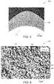
- FIG. 5 shows an optical micrograph 500 of a coated splitter sample of a Pelton bucket. Coating 550 of about 1 mm thickness was applied over a splitter substrate 510 having about 2 mm radius of curvature.
- the coating 550 appears to be smooth and does not have any cracks or delamination. Cracks or delamination was not observed in any of the splitter samples having radius of curvature of about 2 mm and thickness of coating about 1 mm.
- good understanding of relevant parameter ranges was obtained for achieving coatings that are free of cracks and delaminations and further have advantageous radius of curvature and coating thickness. This understanding helped achieve substantially crack free coatings that have both starting hydro-efficiency, efficiency retention, and durability.
- Coating parameters may be further varied and further sets of samples may be tested to achieve thicker coatings on samples having varied radius of curvatures, especially on samples that are having lower radius of curvature such as lower than 1 mm.
- FIG. 6 shows scanning electron micrograph 600 recorded on a cross section of a WC-CoCr coating coated on a Pelton bucket splitter tip having a radius of curvature of about 2 mm.
- the coating thickness was about 1 mm.
- the micrograph exhibits tungsten carbide particles 630 in a CoCr matrix 620.
- a bimodal microstructure of the tungsten carbide particles 630, having relatively large particles 632 and relatively small particles 634 can be seen in the microstructure.
- the average size of the large WC hard particles 632 was less than 1 micron and the average size of the small WC hard particles 634 were observed to be less than 500 nm.
- the test samples having this coating were found to be highly impact tolerant as found by the visual examination conducted after 10 stone shots.
- FIG. 7 gives a graphical illustration 700 of sediment erosion tests, representative of real river site field conditions, conducted for one of the representative test sample, and compared with respective base sample and another similar sample coated by HVOF method.
- the X-axis 702 of the graph represents test duration in minutes and the Y-axis 704 represents normalized erosion width.
- the erosion width of all the coated samples at various time intervals were normalized based on the erosion width of the uncoated base material after 3 hours of erosion, measured with the identical erosion parameters.
- the normalized erosion width of a coated sample at a certain time is normalized by dividing the erosion width obtained after 3 hours of erosion of the base sample.
- a lower normalized erosion width of a sample with a coating indicates a good protection obtained by that coating to the corresponding sample.
- Curve 710 represents the normalized erosion width of the base sample made of 13Cr4Ni stainless steel, a Pelton bucket splitter tip having approximately 2 mm radius of curvature.
- Curve 720 represents the normalized erosion width of the base sample coated with about 0.3 mm thick HVOF coating and curve 750 represents the normalized erosion width of the 1 mm thick coating obtained by HVAF technology on the base sample.
- the results of the experiments show that thick WC-CoCr erosion resistant coating having greater than 0.5 mm thickness can be formed on the wedge-shaped substrate such as Pelton runner edge using the HVAF process. Some observed cracks or delamination may be avoided by optimizing the coating process parameters, system, method of application, and /or technology of HVAF coating.
- the HVAF coating with 1 mm thickness on the splitter having 2 mm radius of curvature was found to give satisfactory results.
- the coatings formed by HVAF were found to be impact tolerant and did not show any damage after 10 shots. From the sediment erosion test, it was seen that some HVAF samples that had crack in the coating layers also did not peel off even after 5 hours of test duration.
Landscapes
- Engineering & Computer Science (AREA)
- Chemical & Material Sciences (AREA)
- Mechanical Engineering (AREA)
- Combustion & Propulsion (AREA)
- General Engineering & Computer Science (AREA)
- Plasma & Fusion (AREA)
- Physics & Mathematics (AREA)
- Chemical Kinetics & Catalysis (AREA)
- Materials Engineering (AREA)
- Metallurgy (AREA)
- Organic Chemistry (AREA)
- Turbine Rotor Nozzle Sealing (AREA)
- Hydraulic Turbines (AREA)
Claims (11)
- Bauteil (100) einer hydroelektrischen Turbine, das umfasst:ein keilförmiges Substrat (210), das einen Spitzenabschnitt (212) und mindestens zwei Seitenabschnitte (216) umfasst; undeine erosionsbeständige Beschichtung (250), die auf dem keilförmigen Substrat (210) aufgebracht ist, wobei die erosionsbeständige Beschichtung (250), die auf dem Spitzenabschnitt (212) aufgebracht ist, mindestens 2 Mal stärker ist als die erosionsbeständige Beschichtung (250), die auf den Seitenabschnitten (216) aufgebracht ist, und wobei die erosionsbeständige Beschichtung (250) mindestens 99,5% Dichte umfasst.
- Bauteil (100) einer hydroelektrischen Turbine nach Anspruch 1, wobei eine Stärke der erosionsbeständigen Beschichtung (250), die auf dem Spitzenabschnitt (212) aufgebracht ist, in einem Bereich von 1 Millimeter bis 3 Millimeter liegt, und eine Stärke der erosionsbeständigen Beschichtung (250), die auf den Seitenabschnitten (216) angeordnet ist, in einem Bereich von 0,3 Millimeter bis 1 Millimeter liegt.
- Bauteil (100) einer hydroelektrischen Turbine nach Anspruch 1 oder 2, das einen Zwischenabschnitt (214) zwischen dem Spitzenabschnitt (212) und den Seitenabschnitten (216) aufweist, und wobei der Zwischenabschnitt (214) eine sich verjüngende Stärke von dem Spitzenabschnitt (212) zu den Seitenabschnitten (216) aufweist.
- Bauteil (100) einer hydroelektrischen Turbine nach einem der Ansprüche 1 bis 3, wobei ein Krümmungsradius des Spitzenabschnitts (212) in einem Bereich von 0,5 Millimeter bis 3,0 Millimeter liegt.
- Bauteil (100) einer hydroelektrischen Turbine nach einem der Ansprüche 1 bis 4, wobei die erosionsbeständige Beschichtung (250) einen Metallmatrix-Verbundstoff umfasst, der eine Kobalt-Chrom-Matrix umfasst.
- Bauteil (100) einer hydroelektrischen Turbine nach einem der Ansprüche 1 bis 5, wobei das keilförmige Substrat (210) einen Splitter einer Pelton-Schaufel, einen W-Ausschnitt der Pelton-Schaufel, eine Pelton-Nadel, einen Sitzring, eine Francis-Leitschaufel, Kaplan-, Rohr- oder Pumpturbine, eine Francis-Laufradschaufel, Kaplan-, Rohr- oder Pumpturbine oder Kombinationen davon umfasst.
- Bauteil (100) einer hydroelektrischen Turbine nach einem der Ansprüche 1 bis 6, wobei die erosionsbeständige Beschichtung (250) rissfrei ist und weniger als 0,5 % Oxidgehalt und Härte von mehr als 1250 HV0,3 umfasst.
- Bauteil (100) einer hydroelektrischen Turbine nach einem der Ansprüche 1 bis 7, das weiter die erosionsbeständige Beschichtung (250) in einem Basisabschnitt (218) des Bauteils (100) einer hydroelektrischen Turbine umfasst, wobei eine Stärke der erosionsbeständigen Beschichtung (250) in einem Bereich von 0,1 Millimeter bis 0,3 Millimeter liegt.
- Bauteil (100) einer hydroelektrischen Turbine nach einem der Ansprüche 1 bis 8, wobei ein Einfallswinkel θ an dem Spitzenabschnitt (212) in einem Bereich von 15 Grad bis 55 Grad liegt.
- Verfahren zum Beschichten eines keilförmigen Substrats (210) eines Bauteils (100) einer hydroelektrischen Turbine, wobei das keilförmige Substrat (210) einen Spitzenabschnitt (212) und mindestens zwei Seitenabschnitte (216) umfasst, wobei das Verfahren umfasst:Beschichten des Spitzenabschnitts (212) des Substrats (210) durch einen Hochgeschwindigkeits-Air-Fuel-Prozess, und dannBeschichten der Seitenabschnitte (216) durch den Hochgeschwindigkeits-Air-Fuel-Prozess, um eine erosionsbeständige Beschichtung (520) sowohl auf dem Spitzenabschnitt (212) als auch auf den Seitenabschnitten (216) derart zu bilden, dass die Beschichtung (250) an dem Spitzenabschnitt (212) mindestens 2 Mal stärker ist als die Beschichtung (250) an den Seitenabschnitten (216).
- Verfahren nach Anspruch 10, das das Beschichten eines Zwischenabschnitts (214) nach dem Beschichten des Spitzenabschnitts (212) und vor dem Beschichten der Seitenabschnitte (216) umfasst, wobei der Zwischenabschnitt (214) zwischen dem Spitzenabschnitt (212) und den Seitenabschnitten (216) angeordnet ist.
Applications Claiming Priority (1)
| Application Number | Priority Date | Filing Date | Title |
|---|---|---|---|
| IN201841041634 | 2018-11-02 |
Publications (2)
| Publication Number | Publication Date |
|---|---|
| EP3647585A1 EP3647585A1 (de) | 2020-05-06 |
| EP3647585B1 true EP3647585B1 (de) | 2021-04-28 |
Family
ID=68382333
Family Applications (1)
| Application Number | Title | Priority Date | Filing Date |
|---|---|---|---|
| EP19205675.2A Active EP3647585B1 (de) | 2018-11-02 | 2019-10-28 | Hydroelektrische turbinenkomponente mit erhöhter lebensdauer und verfahren zu ihrer herstellung |
Country Status (2)
| Country | Link |
|---|---|
| EP (1) | EP3647585B1 (de) |
| CN (1) | CN111140421B (de) |
Cited By (2)
| Publication number | Priority date | Publication date | Assignee | Title |
|---|---|---|---|---|
| WO2023011774A1 (de) | 2021-08-03 | 2023-02-09 | Voith Patent Gmbh | Bauteil einer hydroelektrischen turbine und verfahren zur herstellung |
| WO2023030704A1 (de) | 2021-09-02 | 2023-03-09 | Voith Patent Gmbh | Becher einer turbine vom typ pelton und verfahren zur herstellung |
Families Citing this family (2)
| Publication number | Priority date | Publication date | Assignee | Title |
|---|---|---|---|---|
| CN113236466A (zh) * | 2021-06-25 | 2021-08-10 | 东北大学 | 一种水轮机全新结构的水斗式冲击转轮 |
| CN115837467B (zh) * | 2022-12-08 | 2024-10-08 | 水利部杭州机械设计研究所 | 一种超高水头冲击式水轮机水斗抗冲击磨蚀方法 |
Family Cites Families (10)
| Publication number | Priority date | Publication date | Assignee | Title |
|---|---|---|---|---|
| CH668622A5 (de) * | 1985-11-27 | 1989-01-13 | Escher Wyss Ag | Duese fuer eine freistrahl-wasserturbine und deren herstellung. |
| JP2614370B2 (ja) * | 1991-04-26 | 1997-05-28 | 株式会社東芝 | ニードルチップの製造方法 |
| US7141110B2 (en) * | 2003-11-21 | 2006-11-28 | General Electric Company | Erosion resistant coatings and methods thereof |
| US20070274837A1 (en) * | 2006-05-26 | 2007-11-29 | Thomas Alan Taylor | Blade tip coatings |
| US8790789B2 (en) * | 2008-05-29 | 2014-07-29 | General Electric Company | Erosion and corrosion resistant coatings, methods and articles |
| FR2941639B1 (fr) * | 2009-01-30 | 2012-04-20 | Alstom Hydro France | Composant neuf de machine hydraulique, procede de fabrication ou de maintenance d'un tel composant |
| CN202510273U (zh) * | 2012-01-01 | 2012-10-31 | 白山发电厂 | 耐汽蚀水轮机叶片 |
| US9309895B2 (en) * | 2012-06-18 | 2016-04-12 | Kennametal Inc. | Closed impeller with a coated vane |
| CN103276341B (zh) * | 2013-05-08 | 2015-04-08 | 西安热工研究院有限公司 | 一种水轮机过流部件耐磨蚀涂层的喷涂方法 |
| CN105441857A (zh) * | 2015-11-25 | 2016-03-30 | 广州有色金属研究院 | 一种锂电池极片轧辊机轧辊表面超音速火焰喷涂的方法 |
-
2019
- 2019-10-28 EP EP19205675.2A patent/EP3647585B1/de active Active
- 2019-11-01 CN CN201911060877.9A patent/CN111140421B/zh active Active
Non-Patent Citations (1)
| Title |
|---|
| None * |
Cited By (2)
| Publication number | Priority date | Publication date | Assignee | Title |
|---|---|---|---|---|
| WO2023011774A1 (de) | 2021-08-03 | 2023-02-09 | Voith Patent Gmbh | Bauteil einer hydroelektrischen turbine und verfahren zur herstellung |
| WO2023030704A1 (de) | 2021-09-02 | 2023-03-09 | Voith Patent Gmbh | Becher einer turbine vom typ pelton und verfahren zur herstellung |
Also Published As
| Publication number | Publication date |
|---|---|
| EP3647585A1 (de) | 2020-05-06 |
| CN111140421A (zh) | 2020-05-12 |
| CN111140421B (zh) | 2024-03-08 |
Similar Documents
| Publication | Publication Date | Title |
|---|---|---|
| US7431566B2 (en) | Erosion resistant coatings and methods thereof | |
| EP3647585B1 (de) | Hydroelektrische turbinenkomponente mit erhöhter lebensdauer und verfahren zu ihrer herstellung | |
| Ludwig et al. | WC10Co4Cr coatings deposited by HVOF on martensitic stainless steel for use in hydraulic turbines: Resistance to corrosion and slurry erosion | |
| Mann et al. | Abrasive and erosive wear characteristics of plasma nitriding and HVOF coatings: their application in hydro turbines | |
| KR102630007B1 (ko) | 터빈 틈새 제어 코팅 및 방법 | |
| US8790789B2 (en) | Erosion and corrosion resistant coatings, methods and articles | |
| US20100304084A1 (en) | Protective coatings which provide erosion resistance, and related articles and methods | |
| US20100304181A1 (en) | Protective coatings which provide erosion resistance, and related articles and methods | |
| Nithin et al. | Elevated temperature solid particle erosion behaviour of carbide reinforced CoCrAlY composite coatings | |
| Szala et al. | Cavitation erosion and sliding wear of MCrAlY and NiCrMo coatings deposited by HVOF thermal spraying | |
| Kumar et al. | Slurry erosion performance of high-velocity flame-sprayed Ni-20Al2O3 and Ni-10Al2O3-10TiO2 coatings under accelerated conditions | |
| Medabalimi et al. | Studies on high temperature erosion behavior of HVOF-sprayed (Cr₃C₂-NiCr) Si and WC-Co/NiCrAlY composite coatings | |
| Tailor et al. | Structural and mechanical properties of HVOF sprayed Cr3C2-25% NiCr coating and subsequent erosion wear resistance | |
| Sharma et al. | Slurry erosion performance study of high velocity flame sprayed Ni–Al2O3 coating under hydro accelerated conditions | |
| Sidhu et al. | Comparative characteristic and erosion behavior of NiCr coatings deposited by various high-velocity oxyfuel spray processes | |
| Harish et al. | Enhancing the performance of inconel 601 alloy by erosion resistant WC-CR-CO coated material | |
| Thapa et al. | Erosion behavior of cold sprayed Ni based coating on boiler steel | |
| Shrivastava et al. | Study of fracture toughness and bend test morphologies of HVOF sprayed Cr3C2-25% NiCr coating after heat treatment | |
| Ranjan et al. | Morphological, microstructural, and mechanical study of FGM coatings prepared using the HVOF technique | |
| Mahmud et al. | Mechanical property changes in HVOF sprayed nano-structured WC-17wt.% Ni (80/20) Cr coating with varying substrate roughness | |
| Houdková et al. | Properties of protective NiCr coatings, deposited by Cold Spray technology | |
| Nithin et al. | An Investigation on High Temperature Erosion Behaviour of Plasma Sprayed CoCrAlY/Al 2 O 3/YSZ on Fe and Ni Based Alloys. | |
| Arulvel et al. | Wear/Erosion Resistant High-Temperature Coatings | |
| Singh et al. | Slurry Erosion Performance of Detonation Gun Sprayed Stellite-6 on 13Cr4Ni Hydro Turbine Steel at Two Different Angles under Hydro-accelerated Conditions | |
| Kumar et al. | To study erosion behavior of Cr |
Legal Events
| Date | Code | Title | Description |
|---|---|---|---|
| PUAI | Public reference made under article 153(3) epc to a published international application that has entered the european phase |
Free format text: ORIGINAL CODE: 0009012 |
|
| STAA | Information on the status of an ep patent application or granted ep patent |
Free format text: STATUS: THE APPLICATION HAS BEEN PUBLISHED |
|
| AK | Designated contracting states |
Kind code of ref document: A1 Designated state(s): AL AT BE BG CH CY CZ DE DK EE ES FI FR GB GR HR HU IE IS IT LI LT LU LV MC MK MT NL NO PL PT RO RS SE SI SK SM TR |
|
| AX | Request for extension of the european patent |
Extension state: BA ME |
|
| STAA | Information on the status of an ep patent application or granted ep patent |
Free format text: STATUS: REQUEST FOR EXAMINATION WAS MADE |
|
| 17P | Request for examination filed |
Effective date: 20200910 |
|
| RBV | Designated contracting states (corrected) |
Designated state(s): AL AT BE BG CH CY CZ DE DK EE ES FI FR GB GR HR HU IE IS IT LI LT LU LV MC MK MT NL NO PL PT RO RS SE SI SK SM TR |
|
| GRAP | Despatch of communication of intention to grant a patent |
Free format text: ORIGINAL CODE: EPIDOSNIGR1 |
|
| STAA | Information on the status of an ep patent application or granted ep patent |
Free format text: STATUS: GRANT OF PATENT IS INTENDED |
|
| INTG | Intention to grant announced |
Effective date: 20201125 |
|
| GRAS | Grant fee paid |
Free format text: ORIGINAL CODE: EPIDOSNIGR3 |
|
| GRAA | (expected) grant |
Free format text: ORIGINAL CODE: 0009210 |
|
| STAA | Information on the status of an ep patent application or granted ep patent |
Free format text: STATUS: THE PATENT HAS BEEN GRANTED |
|
| AK | Designated contracting states |
Kind code of ref document: B1 Designated state(s): AL AT BE BG CH CY CZ DE DK EE ES FI FR GB GR HR HU IE IS IT LI LT LU LV MC MK MT NL NO PL PT RO RS SE SI SK SM TR |
|
| REG | Reference to a national code |
Ref country code: GB Ref legal event code: FG4D |
|
| REG | Reference to a national code |
Ref country code: CH Ref legal event code: EP |
|
| REG | Reference to a national code |
Ref country code: AT Ref legal event code: REF Ref document number: 1387338 Country of ref document: AT Kind code of ref document: T Effective date: 20210515 |
|
| REG | Reference to a national code |
Ref country code: DE Ref legal event code: R096 Ref document number: 602019004266 Country of ref document: DE |
|
| REG | Reference to a national code |
Ref country code: IE Ref legal event code: FG4D |
|
| REG | Reference to a national code |
Ref country code: LT Ref legal event code: MG9D |
|
| PG25 | Lapsed in a contracting state [announced via postgrant information from national office to epo] |
Ref country code: FI Free format text: LAPSE BECAUSE OF FAILURE TO SUBMIT A TRANSLATION OF THE DESCRIPTION OR TO PAY THE FEE WITHIN THE PRESCRIBED TIME-LIMIT Effective date: 20210428 Ref country code: HR Free format text: LAPSE BECAUSE OF FAILURE TO SUBMIT A TRANSLATION OF THE DESCRIPTION OR TO PAY THE FEE WITHIN THE PRESCRIBED TIME-LIMIT Effective date: 20210428 Ref country code: LT Free format text: LAPSE BECAUSE OF FAILURE TO SUBMIT A TRANSLATION OF THE DESCRIPTION OR TO PAY THE FEE WITHIN THE PRESCRIBED TIME-LIMIT Effective date: 20210428 Ref country code: NL Free format text: LAPSE BECAUSE OF FAILURE TO SUBMIT A TRANSLATION OF THE DESCRIPTION OR TO PAY THE FEE WITHIN THE PRESCRIBED TIME-LIMIT Effective date: 20210428 Ref country code: BG Free format text: LAPSE BECAUSE OF FAILURE TO SUBMIT A TRANSLATION OF THE DESCRIPTION OR TO PAY THE FEE WITHIN THE PRESCRIBED TIME-LIMIT Effective date: 20210728 |
|
| PG25 | Lapsed in a contracting state [announced via postgrant information from national office to epo] |
Ref country code: PT Free format text: LAPSE BECAUSE OF FAILURE TO SUBMIT A TRANSLATION OF THE DESCRIPTION OR TO PAY THE FEE WITHIN THE PRESCRIBED TIME-LIMIT Effective date: 20210830 Ref country code: SE Free format text: LAPSE BECAUSE OF FAILURE TO SUBMIT A TRANSLATION OF THE DESCRIPTION OR TO PAY THE FEE WITHIN THE PRESCRIBED TIME-LIMIT Effective date: 20210428 Ref country code: RS Free format text: LAPSE BECAUSE OF FAILURE TO SUBMIT A TRANSLATION OF THE DESCRIPTION OR TO PAY THE FEE WITHIN THE PRESCRIBED TIME-LIMIT Effective date: 20210428 Ref country code: PL Free format text: LAPSE BECAUSE OF FAILURE TO SUBMIT A TRANSLATION OF THE DESCRIPTION OR TO PAY THE FEE WITHIN THE PRESCRIBED TIME-LIMIT Effective date: 20210428 Ref country code: LV Free format text: LAPSE BECAUSE OF FAILURE TO SUBMIT A TRANSLATION OF THE DESCRIPTION OR TO PAY THE FEE WITHIN THE PRESCRIBED TIME-LIMIT Effective date: 20210428 Ref country code: NO Free format text: LAPSE BECAUSE OF FAILURE TO SUBMIT A TRANSLATION OF THE DESCRIPTION OR TO PAY THE FEE WITHIN THE PRESCRIBED TIME-LIMIT Effective date: 20210728 Ref country code: GR Free format text: LAPSE BECAUSE OF FAILURE TO SUBMIT A TRANSLATION OF THE DESCRIPTION OR TO PAY THE FEE WITHIN THE PRESCRIBED TIME-LIMIT Effective date: 20210729 Ref country code: IS Free format text: LAPSE BECAUSE OF FAILURE TO SUBMIT A TRANSLATION OF THE DESCRIPTION OR TO PAY THE FEE WITHIN THE PRESCRIBED TIME-LIMIT Effective date: 20210828 |
|
| REG | Reference to a national code |
Ref country code: NL Ref legal event code: MP Effective date: 20210428 |
|
| PG25 | Lapsed in a contracting state [announced via postgrant information from national office to epo] |
Ref country code: ES Free format text: LAPSE BECAUSE OF FAILURE TO SUBMIT A TRANSLATION OF THE DESCRIPTION OR TO PAY THE FEE WITHIN THE PRESCRIBED TIME-LIMIT Effective date: 20210428 Ref country code: EE Free format text: LAPSE BECAUSE OF FAILURE TO SUBMIT A TRANSLATION OF THE DESCRIPTION OR TO PAY THE FEE WITHIN THE PRESCRIBED TIME-LIMIT Effective date: 20210428 Ref country code: SK Free format text: LAPSE BECAUSE OF FAILURE TO SUBMIT A TRANSLATION OF THE DESCRIPTION OR TO PAY THE FEE WITHIN THE PRESCRIBED TIME-LIMIT Effective date: 20210428 Ref country code: CZ Free format text: LAPSE BECAUSE OF FAILURE TO SUBMIT A TRANSLATION OF THE DESCRIPTION OR TO PAY THE FEE WITHIN THE PRESCRIBED TIME-LIMIT Effective date: 20210428 Ref country code: DK Free format text: LAPSE BECAUSE OF FAILURE TO SUBMIT A TRANSLATION OF THE DESCRIPTION OR TO PAY THE FEE WITHIN THE PRESCRIBED TIME-LIMIT Effective date: 20210428 Ref country code: RO Free format text: LAPSE BECAUSE OF FAILURE TO SUBMIT A TRANSLATION OF THE DESCRIPTION OR TO PAY THE FEE WITHIN THE PRESCRIBED TIME-LIMIT Effective date: 20210428 Ref country code: SM Free format text: LAPSE BECAUSE OF FAILURE TO SUBMIT A TRANSLATION OF THE DESCRIPTION OR TO PAY THE FEE WITHIN THE PRESCRIBED TIME-LIMIT Effective date: 20210428 |
|
| REG | Reference to a national code |
Ref country code: DE Ref legal event code: R097 Ref document number: 602019004266 Country of ref document: DE |
|
| PLBE | No opposition filed within time limit |
Free format text: ORIGINAL CODE: 0009261 |
|
| STAA | Information on the status of an ep patent application or granted ep patent |
Free format text: STATUS: NO OPPOSITION FILED WITHIN TIME LIMIT |
|
| 26N | No opposition filed |
Effective date: 20220131 |
|
| REG | Reference to a national code |
Ref country code: DE Ref legal event code: R119 Ref document number: 602019004266 Country of ref document: DE |
|
| PG25 | Lapsed in a contracting state [announced via postgrant information from national office to epo] |
Ref country code: IS Free format text: LAPSE BECAUSE OF FAILURE TO SUBMIT A TRANSLATION OF THE DESCRIPTION OR TO PAY THE FEE WITHIN THE PRESCRIBED TIME-LIMIT Effective date: 20210828 Ref country code: AL Free format text: LAPSE BECAUSE OF FAILURE TO SUBMIT A TRANSLATION OF THE DESCRIPTION OR TO PAY THE FEE WITHIN THE PRESCRIBED TIME-LIMIT Effective date: 20210428 |
|
| REG | Reference to a national code |
Ref country code: BE Ref legal event code: MM Effective date: 20211031 |
|
| PG25 | Lapsed in a contracting state [announced via postgrant information from national office to epo] |
Ref country code: MC Free format text: LAPSE BECAUSE OF FAILURE TO SUBMIT A TRANSLATION OF THE DESCRIPTION OR TO PAY THE FEE WITHIN THE PRESCRIBED TIME-LIMIT Effective date: 20210428 |
|
| PG25 | Lapsed in a contracting state [announced via postgrant information from national office to epo] |
Ref country code: LU Free format text: LAPSE BECAUSE OF NON-PAYMENT OF DUE FEES Effective date: 20211028 Ref country code: DE Free format text: LAPSE BECAUSE OF NON-PAYMENT OF DUE FEES Effective date: 20220503 Ref country code: BE Free format text: LAPSE BECAUSE OF NON-PAYMENT OF DUE FEES Effective date: 20211031 |
|
| PG25 | Lapsed in a contracting state [announced via postgrant information from national office to epo] |
Ref country code: IE Free format text: LAPSE BECAUSE OF NON-PAYMENT OF DUE FEES Effective date: 20211028 |
|
| P01 | Opt-out of the competence of the unified patent court (upc) registered |
Effective date: 20230522 |
|
| PG25 | Lapsed in a contracting state [announced via postgrant information from national office to epo] |
Ref country code: CY Free format text: LAPSE BECAUSE OF FAILURE TO SUBMIT A TRANSLATION OF THE DESCRIPTION OR TO PAY THE FEE WITHIN THE PRESCRIBED TIME-LIMIT Effective date: 20210428 |
|
| PG25 | Lapsed in a contracting state [announced via postgrant information from national office to epo] |
Ref country code: HU Free format text: LAPSE BECAUSE OF FAILURE TO SUBMIT A TRANSLATION OF THE DESCRIPTION OR TO PAY THE FEE WITHIN THE PRESCRIBED TIME-LIMIT; INVALID AB INITIO Effective date: 20191028 |
|
| REG | Reference to a national code |
Ref country code: AT Ref legal event code: UEP Ref document number: 1387338 Country of ref document: AT Kind code of ref document: T Effective date: 20210428 |
|
| PG25 | Lapsed in a contracting state [announced via postgrant information from national office to epo] |
Ref country code: MK Free format text: LAPSE BECAUSE OF FAILURE TO SUBMIT A TRANSLATION OF THE DESCRIPTION OR TO PAY THE FEE WITHIN THE PRESCRIBED TIME-LIMIT Effective date: 20210428 |
|
| GBPC | Gb: european patent ceased through non-payment of renewal fee |
Effective date: 20231028 |
|
| PG25 | Lapsed in a contracting state [announced via postgrant information from national office to epo] |
Ref country code: GB Free format text: LAPSE BECAUSE OF NON-PAYMENT OF DUE FEES Effective date: 20231028 |
|
| PG25 | Lapsed in a contracting state [announced via postgrant information from national office to epo] |
Ref country code: GB Free format text: LAPSE BECAUSE OF NON-PAYMENT OF DUE FEES Effective date: 20231028 |
|
| PG25 | Lapsed in a contracting state [announced via postgrant information from national office to epo] |
Ref country code: MT Free format text: LAPSE BECAUSE OF FAILURE TO SUBMIT A TRANSLATION OF THE DESCRIPTION OR TO PAY THE FEE WITHIN THE PRESCRIBED TIME-LIMIT Effective date: 20210428 |
|
| PGFP | Annual fee paid to national office [announced via postgrant information from national office to epo] |
Ref country code: FR Payment date: 20240919 Year of fee payment: 6 |
|
| PGFP | Annual fee paid to national office [announced via postgrant information from national office to epo] |
Ref country code: IT Payment date: 20240919 Year of fee payment: 6 |
|
| PGFP | Annual fee paid to national office [announced via postgrant information from national office to epo] |
Ref country code: AT Payment date: 20240923 Year of fee payment: 6 |
|
| PGFP | Annual fee paid to national office [announced via postgrant information from national office to epo] |
Ref country code: CH Payment date: 20241101 Year of fee payment: 6 |
|
| PG25 | Lapsed in a contracting state [announced via postgrant information from national office to epo] |
Ref country code: TR Free format text: LAPSE BECAUSE OF FAILURE TO SUBMIT A TRANSLATION OF THE DESCRIPTION OR TO PAY THE FEE WITHIN THE PRESCRIBED TIME-LIMIT Effective date: 20210428 |