EP3647619A1 - Arbre d'entraînement composite assemblés de plusieurs pièces avec accouplements à soufflets - Google Patents
Arbre d'entraînement composite assemblés de plusieurs pièces avec accouplements à soufflets Download PDFInfo
- Publication number
- EP3647619A1 EP3647619A1 EP19205591.1A EP19205591A EP3647619A1 EP 3647619 A1 EP3647619 A1 EP 3647619A1 EP 19205591 A EP19205591 A EP 19205591A EP 3647619 A1 EP3647619 A1 EP 3647619A1
- Authority
- EP
- European Patent Office
- Prior art keywords
- drive shaft
- diaphragm
- tubular portion
- set forth
- diaphragms
- Prior art date
- Legal status (The legal status is an assumption and is not a legal conclusion. Google has not performed a legal analysis and makes no representation as to the accuracy of the status listed.)
- Granted
Links
Images


Classifications
-
- F—MECHANICAL ENGINEERING; LIGHTING; HEATING; WEAPONS; BLASTING
- F16—ENGINEERING ELEMENTS AND UNITS; GENERAL MEASURES FOR PRODUCING AND MAINTAINING EFFECTIVE FUNCTIONING OF MACHINES OR INSTALLATIONS; THERMAL INSULATION IN GENERAL
- F16D—COUPLINGS FOR TRANSMITTING ROTATION; CLUTCHES; BRAKES
- F16D1/00—Couplings for rigidly connecting two coaxial shafts or other movable machine elements
- F16D1/06—Couplings for rigidly connecting two coaxial shafts or other movable machine elements for attachment of a member on a shaft or on a shaft-end
- F16D1/064—Couplings for rigidly connecting two coaxial shafts or other movable machine elements for attachment of a member on a shaft or on a shaft-end non-disconnectable
- F16D1/068—Couplings for rigidly connecting two coaxial shafts or other movable machine elements for attachment of a member on a shaft or on a shaft-end non-disconnectable involving gluing, welding or the like
-
- F—MECHANICAL ENGINEERING; LIGHTING; HEATING; WEAPONS; BLASTING
- F16—ENGINEERING ELEMENTS AND UNITS; GENERAL MEASURES FOR PRODUCING AND MAINTAINING EFFECTIVE FUNCTIONING OF MACHINES OR INSTALLATIONS; THERMAL INSULATION IN GENERAL
- F16C—SHAFTS; FLEXIBLE SHAFTS; ELEMENTS OR CRANKSHAFT MECHANISMS; ROTARY BODIES OTHER THAN GEARING ELEMENTS; BEARINGS
- F16C3/00—Shafts; Axles; Cranks; Eccentrics
- F16C3/02—Shafts; Axles
- F16C3/026—Shafts made of fibre reinforced resin
-
- F—MECHANICAL ENGINEERING; LIGHTING; HEATING; WEAPONS; BLASTING
- F16—ENGINEERING ELEMENTS AND UNITS; GENERAL MEASURES FOR PRODUCING AND MAINTAINING EFFECTIVE FUNCTIONING OF MACHINES OR INSTALLATIONS; THERMAL INSULATION IN GENERAL
- F16C—SHAFTS; FLEXIBLE SHAFTS; ELEMENTS OR CRANKSHAFT MECHANISMS; ROTARY BODIES OTHER THAN GEARING ELEMENTS; BEARINGS
- F16C3/00—Shafts; Axles; Cranks; Eccentrics
- F16C3/02—Shafts; Axles
- F16C3/023—Shafts; Axles made of several parts, e.g. by welding
-
- F—MECHANICAL ENGINEERING; LIGHTING; HEATING; WEAPONS; BLASTING
- F16—ENGINEERING ELEMENTS AND UNITS; GENERAL MEASURES FOR PRODUCING AND MAINTAINING EFFECTIVE FUNCTIONING OF MACHINES OR INSTALLATIONS; THERMAL INSULATION IN GENERAL
- F16D—COUPLINGS FOR TRANSMITTING ROTATION; CLUTCHES; BRAKES
- F16D1/00—Couplings for rigidly connecting two coaxial shafts or other movable machine elements
- F16D1/02—Couplings for rigidly connecting two coaxial shafts or other movable machine elements for connecting two abutting shafts or the like
- F16D1/027—Couplings for rigidly connecting two coaxial shafts or other movable machine elements for connecting two abutting shafts or the like non-disconnectable, e.g. involving gluing, welding or the like
-
- F—MECHANICAL ENGINEERING; LIGHTING; HEATING; WEAPONS; BLASTING
- F16—ENGINEERING ELEMENTS AND UNITS; GENERAL MEASURES FOR PRODUCING AND MAINTAINING EFFECTIVE FUNCTIONING OF MACHINES OR INSTALLATIONS; THERMAL INSULATION IN GENERAL
- F16D—COUPLINGS FOR TRANSMITTING ROTATION; CLUTCHES; BRAKES
- F16D3/00—Yielding couplings, i.e. with means permitting movement between the connected parts during the drive
- F16D3/50—Yielding couplings, i.e. with means permitting movement between the connected parts during the drive with the coupling parts connected by one or more intermediate members
- F16D3/72—Yielding couplings, i.e. with means permitting movement between the connected parts during the drive with the coupling parts connected by one or more intermediate members with axially-spaced attachments to the coupling parts
- F16D3/725—Yielding couplings, i.e. with means permitting movement between the connected parts during the drive with the coupling parts connected by one or more intermediate members with axially-spaced attachments to the coupling parts with an intermediate member made of fibre-reinforced resin
-
- F—MECHANICAL ENGINEERING; LIGHTING; HEATING; WEAPONS; BLASTING
- F16—ENGINEERING ELEMENTS AND UNITS; GENERAL MEASURES FOR PRODUCING AND MAINTAINING EFFECTIVE FUNCTIONING OF MACHINES OR INSTALLATIONS; THERMAL INSULATION IN GENERAL
- F16C—SHAFTS; FLEXIBLE SHAFTS; ELEMENTS OR CRANKSHAFT MECHANISMS; ROTARY BODIES OTHER THAN GEARING ELEMENTS; BEARINGS
- F16C2208/00—Plastics; Synthetic resins, e.g. rubbers
- F16C2208/02—Plastics; Synthetic resins, e.g. rubbers comprising fillers, fibres
-
- F—MECHANICAL ENGINEERING; LIGHTING; HEATING; WEAPONS; BLASTING
- F16—ENGINEERING ELEMENTS AND UNITS; GENERAL MEASURES FOR PRODUCING AND MAINTAINING EFFECTIVE FUNCTIONING OF MACHINES OR INSTALLATIONS; THERMAL INSULATION IN GENERAL
- F16C—SHAFTS; FLEXIBLE SHAFTS; ELEMENTS OR CRANKSHAFT MECHANISMS; ROTARY BODIES OTHER THAN GEARING ELEMENTS; BEARINGS
- F16C2226/00—Joining parts; Fastening; Assembling or mounting parts
- F16C2226/30—Material joints
- F16C2226/36—Material joints by welding
-
- F—MECHANICAL ENGINEERING; LIGHTING; HEATING; WEAPONS; BLASTING
- F16—ENGINEERING ELEMENTS AND UNITS; GENERAL MEASURES FOR PRODUCING AND MAINTAINING EFFECTIVE FUNCTIONING OF MACHINES OR INSTALLATIONS; THERMAL INSULATION IN GENERAL
- F16C—SHAFTS; FLEXIBLE SHAFTS; ELEMENTS OR CRANKSHAFT MECHANISMS; ROTARY BODIES OTHER THAN GEARING ELEMENTS; BEARINGS
- F16C2326/00—Articles relating to transporting
- F16C2326/01—Parts of vehicles in general
- F16C2326/06—Drive shafts
-
- F—MECHANICAL ENGINEERING; LIGHTING; HEATING; WEAPONS; BLASTING
- F16—ENGINEERING ELEMENTS AND UNITS; GENERAL MEASURES FOR PRODUCING AND MAINTAINING EFFECTIVE FUNCTIONING OF MACHINES OR INSTALLATIONS; THERMAL INSULATION IN GENERAL
- F16C—SHAFTS; FLEXIBLE SHAFTS; ELEMENTS OR CRANKSHAFT MECHANISMS; ROTARY BODIES OTHER THAN GEARING ELEMENTS; BEARINGS
- F16C2326/00—Articles relating to transporting
- F16C2326/43—Aeroplanes; Helicopters
-
- F—MECHANICAL ENGINEERING; LIGHTING; HEATING; WEAPONS; BLASTING
- F16—ENGINEERING ELEMENTS AND UNITS; GENERAL MEASURES FOR PRODUCING AND MAINTAINING EFFECTIVE FUNCTIONING OF MACHINES OR INSTALLATIONS; THERMAL INSULATION IN GENERAL
- F16D—COUPLINGS FOR TRANSMITTING ROTATION; CLUTCHES; BRAKES
- F16D1/00—Couplings for rigidly connecting two coaxial shafts or other movable machine elements
- F16D1/06—Couplings for rigidly connecting two coaxial shafts or other movable machine elements for attachment of a member on a shaft or on a shaft-end
- F16D1/08—Couplings for rigidly connecting two coaxial shafts or other movable machine elements for attachment of a member on a shaft or on a shaft-end with clamping hub; with hub and longitudinal key
- F16D1/0894—Couplings for rigidly connecting two coaxial shafts or other movable machine elements for attachment of a member on a shaft or on a shaft-end with clamping hub; with hub and longitudinal key with other than axial keys, e.g. diametral pins, cotter pins and no other radial clamping
-
- F—MECHANICAL ENGINEERING; LIGHTING; HEATING; WEAPONS; BLASTING
- F16—ENGINEERING ELEMENTS AND UNITS; GENERAL MEASURES FOR PRODUCING AND MAINTAINING EFFECTIVE FUNCTIONING OF MACHINES OR INSTALLATIONS; THERMAL INSULATION IN GENERAL
- F16D—COUPLINGS FOR TRANSMITTING ROTATION; CLUTCHES; BRAKES
- F16D2200/00—Materials; Production methods therefor
- F16D2200/006—Materials; Production methods therefor containing fibres or particles
-
- F—MECHANICAL ENGINEERING; LIGHTING; HEATING; WEAPONS; BLASTING
- F16—ENGINEERING ELEMENTS AND UNITS; GENERAL MEASURES FOR PRODUCING AND MAINTAINING EFFECTIVE FUNCTIONING OF MACHINES OR INSTALLATIONS; THERMAL INSULATION IN GENERAL
- F16D—COUPLINGS FOR TRANSMITTING ROTATION; CLUTCHES; BRAKES
- F16D2250/00—Manufacturing; Assembly
- F16D2250/0061—Joining
- F16D2250/0076—Welding, brazing
-
- Y—GENERAL TAGGING OF NEW TECHNOLOGICAL DEVELOPMENTS; GENERAL TAGGING OF CROSS-SECTIONAL TECHNOLOGIES SPANNING OVER SEVERAL SECTIONS OF THE IPC; TECHNICAL SUBJECTS COVERED BY FORMER USPC CROSS-REFERENCE ART COLLECTIONS [XRACs] AND DIGESTS
- Y10—TECHNICAL SUBJECTS COVERED BY FORMER USPC
- Y10S—TECHNICAL SUBJECTS COVERED BY FORMER USPC CROSS-REFERENCE ART COLLECTIONS [XRACs] AND DIGESTS
- Y10S138/00—Pipes and tubular conduits
- Y10S138/02—Glass fiber
-
- Y—GENERAL TAGGING OF NEW TECHNOLOGICAL DEVELOPMENTS; GENERAL TAGGING OF CROSS-SECTIONAL TECHNOLOGIES SPANNING OVER SEVERAL SECTIONS OF THE IPC; TECHNICAL SUBJECTS COVERED BY FORMER USPC CROSS-REFERENCE ART COLLECTIONS [XRACs] AND DIGESTS
- Y10—TECHNICAL SUBJECTS COVERED BY FORMER USPC
- Y10S—TECHNICAL SUBJECTS COVERED BY FORMER USPC CROSS-REFERENCE ART COLLECTIONS [XRACs] AND DIGESTS
- Y10S285/00—Pipe joints or couplings
- Y10S285/919—Resinous
Definitions
- This application relates to a drive shaft formed of composite materials.
- Drive shafts are used to transfer load between drive system components, e.g., parts of engine, gear system, rotor blades, etc.
- Drive shafts in modern mechanical systems must be capable of transmitting primarily high torque at high speed and yet are subject to a number of design constraints. As an example, weight is a driving concern for the designer of any number of mechanical systems.
- drive shafts must be able to resist, according to specified criteria of structural integrity, the torque load along with other load components, such as, for example, bending and/or axial loads. This must all occur as the relative position of an input shaft and a driven shaft connected by the coupling might flex or otherwise vary.
- drive shafts including diaphragm members at each connection end of a shaft tube.
- the diaphragms have an undulation to allow some flexing.
- a relatively rigid connecting tube connects two diaphragms to provide torsional stiffness.
- the tube is formed of composite materials whereas the diaphragms are formed of metallic materials.
- the diaphragms and the tube are formed as one integral unit from composite materials.
- a drive shaft is for selectively connecting a drive input to an output.
- the drive shaft has a tubular portion, a first diaphragm member, and a second diaphragm member displaced axially along the shaft from the first diaphragm member.
- the first and second diaphragm members each are formed with two axial ends. At least one undulation extends radially of the ends.
- the tubular portion connects the first and second diaphragm members.
- the first and second diaphragm members and the tubular portion are formed of fiber-reinforced polymer matrix composites.
- the first and second diaphragm members are connected to first and second axial ends of the tubular portion through a mechanical connection at joints.
- a method of forming a drive shaft is also disclosed.
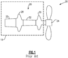
- Figure 1 shows a schematic side view of mechanical drive system 20 which may be incorporated into a number of applications.
- the particular disclosed application is an aerospace application 19, shown schematically. Examples include fixed wing aircraft or helicopter applications.
- a driving input 22, such as, for example, engine or gear system, drives an output 24, illustrated schematically, for example, as a propeller, through a drive coupling 26.
- Drive shaft 26 includes a pair of diaphragms 28 and 30 which connect ends of the shaft 26 to the drive input 22 and the output 24.
- the example drive shafts disclosed are axisymmetric, but other shafts may benefit from this disclosure.
- the diaphragms have an undulation that allow low flexural and axial stiffness under bending and/or axial loads applied between center axis of the drive input 22 and output 24.
- a tube 32 connects the diaphragms 28 and 30, and the entire shaft 26, including the tube 32 and the diaphragms 28 and 30, is relatively stiff under torsional load.
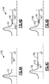
- Figure 2A shows a first step 50 in a method of forming a drive coupling which may be incorporated into the location of drive coupling 26.
- the individual diaphragms 52 are formed separately and the tube 60 is formed separately.
- there can be one or more undulations 58 in the diaphragm 52 such that there are radially inner ends 54 and 56 and a radially outwardly extending undulation 58.
- designs of the diaphragms 52 can be different and can use, at least, one radially inwardly extending undulation either instead of radially outwardly undulation(s) or in combination with them.
- the components 52 and 60 may be formed of the same or different fiber-reinforced polymer matrix composite materials.
- the matrix can be a thermoplastic polymer.
- the matrix can be a thermoset polymer.
- Different types of reinforcing fibers such as, for example, carbon fibers, glass fibers, organic fibers, or their combinations can be used in different embodiments.
- the same or different fabrication processes such as for example, automated fiber placement, filament winding, braiding, wrapping, etc. can be used to make separate composite tubes and diaphragms.
- FIG. 2B shows a subsequent step 50.
- an area 62 is welded to connect the diaphragm 52 to the tube 60 for composite materials with thermoplastic matrix.
- the welding process can include steps such as preparation of contact surfaces, application of heat and pressure, and cooling.
- typically used welding methods for thermoplastic materials such as, for example, hot gas welding, speed tip welding, contact welding, hot plate welding, non-contact/infrared welding, high frequency welding can be used.
- a second diaphragm is attached to an opposed end by similar means to provide a similar load transfer.
- This composite drive shaft based on connection of previously fabricated separate composite tube and diaphragms, is provided that is relatively easy to manufacture compared to the prior art method of forming an integral one-piece shaft incorporating both the diaphragms and the shaft during their fabrication.
- Figure 3A shows an alternative, wherein the area 62 may be welded.
- an inner sleeve 70 can also be welded or otherwise secured in place and spans the joint 62 such that axial ends of the sleeve 70 underlie axial ends of the diaphragm 52 and the tube 60.
- Sleeve 70 (and other sleeves disclosed below) may be formed of a thermoset polymer, as an example, or alternatively materials similar to those used in the diaphragm and tube can be used.
- Figure 3B shows an alternative wherein the sleeve 72 is on a radially outer surface of the shaft.
- Figure 3C shows yet another embodiment wherein there is an inner sleeve 70 and an outer sleeve 72 both spanning the joints 62.
- the composite sleeves 70 and 72 shown in Figures 3A-3B , can be fabricated from the same or different material than the diaphragm 52 and/or tube 60, and can be fabrication using the same or different methods.
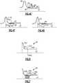
- Figure 4A shows an initial step of a distinct method 150 wherein the diaphragm 52 is again formed, however, the tube 160 has a somewhat different diameter than in Figure 2A .
- Figure 4B shows a subsequent step 159.
- An axial end 56 of the diaphragm 52 overlies an axial end of the tube 160, such that the mechanical securement, such as by welding or other attachment occurs along the surface 162.
- Surface 162 is at a radially outer surface of the tube 160, and a radially inner surface of the end 56 of the diaphragm 52.
- Figure 4C shows an alternative wherein the connection 170 is between a radially inner surface of the tube 160 and a radially outer surface of the end 56 of the diaphragm 52.
- Figure 4D shows an alternative wherein radial fasteners, such as for example, pins, rivets, or bolts, 180 secure the diaphragm end 56 to the tube 160.
- the tube 160 and the diaphragm 52 can be made of fiber reinforced composite with thermoset matrix. It should be understood that this same type of radial fasteners arrangement could be utilized with the Figure 4C positioning. The same radial fasteners arrangement can also complement the above-mentioned solutions shown in Figures 3A-3C and Figures 4E-4G , shown below.
- Figure 4E shows an embodiment wherein the end 82 of the tube 80 is within the end 56 of the diaphragm 52.
- an outer sleeve 84 is provided having a radially inward step 90 secured to the outer surface of the shaft 80.
- a ramp 86 and a radially outer step 88 are secured radially outwardly of the end 56.
- Figure 4F shows basically a mirror to the Figure 4E embodiment.
- the tube 92 extends radially outwardly of the end 56 and the sleeve 94 has the radially outer step 96 secured to the inner surface of the shaft 92.
- Ramp 100 leads to a radially inner step 98 secured to a radially inner surface of the end 56 of the diaphragm 52.
- Figure 4G shows an embodiment wherein there is a sleeve 84 radially outwardly of the end 56 and the tube 110 has a ramp 112 leading into a radially inner step 114, which is secured to a radially inner surface of the end 56 of the diaphragm 52.
- the composite sleeves 84 and 94 shown in Figures 4E-4G , can be fabricated from the same or different material than the diaphragm 52 and/or tube 60, and can be fabrication using the same or different methods (as an example thermoset polymers may be used).
- Figure 5 schematically shows a side view of diaphragm 252 secured to a tube 260 at the joint 62.
- a cross-section 6-6 extends through a radial thickness of the connection.
- Figure 6B shows an alternative wherein there are inside teeth 214 as a component of inside part 212 of the shaft 260 interspersed with outside teeth 210 from the diaphragm. Similar implementation can be in other embodiments where shaft is inside and the diaphragm is outside or if an inner sleeve is used
- Figure 6C shows a mirror to the Figure 6B embodiment wherein the outside portion 261 is formed with the diaphragm 252 and the inside teeth 218 and 220 are again interspersed in the radial direction. Similar implementation can be in other embodiments where diaphragm is inside and the shaft is outside or if an outer sleeve is used.
- Figure 6D shows an embodiment where both the diaphragm 234 and shaft 236 both have the external portions 230 and 234 and the spaced teeth 232 and 236. Similar implementation can be in other embodiments where diaphragm is inside and the shaft is outside or if an inner or/and outer sleeves are used.
- Figure 7 shows a side view of embodiments illustrating examples shown in Figures 6A or 6B .
- the shaft 304 is connected to the diaphragm 300 at a joint with circumferentially spaced teeth 302 on the diaphragm 300 and teeth 306 on the tube 308, and fitting into grooves 308 and 310 on the tube and diaphragm, respectively.
- the teeth and grooves can have ends with uniformly or non-uniformly curved shapes.
- All of the several embodiments provide alternative for ensuring a secure connection between the diaphragms and the tube.
- the resulting composite drive shaft will achieve weight reduction compared to the prior art, simplify manufacture and assembly, and allow a designer great freedom in achieving design goals.
- a method of forming a drive shaft includes the steps of forming a first and second diaphragm.
- a tube is separately formed.
- the first and second diaphragms and the tube are formed of a fiber-reinforced polymer-matrix composite.
- One end of each of the first and second diaphragms is mechanically connected to first and second ends of the tube.
- a drive shaft for selectively connecting a drive input to an output could be said to include a tubular portion, a first diaphragm member, and a second diaphragm member displaced axially along the shaft from the first diaphragm member.
- the first and second diaphragm members each are formed with two axial ends. At least one undulation extends radially of the ends.
- the tubular portion connects the first and second diaphragm members.
- the first and second diaphragm members and the tubular portion are formed of fiber-reinforced polymer matrix composites.
- the first and second diaphragm members connect to first and second axial ends of the tubular portion through a mechanical connection at joints.
Landscapes
- Engineering & Computer Science (AREA)
- General Engineering & Computer Science (AREA)
- Mechanical Engineering (AREA)
- Ocean & Marine Engineering (AREA)
- Shafts, Cranks, Connecting Bars, And Related Bearings (AREA)
Applications Claiming Priority (1)
| Application Number | Priority Date | Filing Date | Title |
|---|---|---|---|
| US16/173,364 US11396904B2 (en) | 2018-10-29 | 2018-10-29 | Composite drive shafts |
Publications (2)
| Publication Number | Publication Date |
|---|---|
| EP3647619A1 true EP3647619A1 (fr) | 2020-05-06 |
| EP3647619B1 EP3647619B1 (fr) | 2024-04-17 |
Family
ID=68382276
Family Applications (1)
| Application Number | Title | Priority Date | Filing Date |
|---|---|---|---|
| EP19205591.1A Active EP3647619B1 (fr) | 2018-10-29 | 2019-10-28 | Arbre d'entraînement composite assemblés de plusieurs pièces avec accouplements à soufflets |
Country Status (2)
| Country | Link |
|---|---|
| US (2) | US11396904B2 (fr) |
| EP (1) | EP3647619B1 (fr) |
Families Citing this family (4)
| Publication number | Priority date | Publication date | Assignee | Title |
|---|---|---|---|---|
| US11486439B2 (en) | 2019-02-18 | 2022-11-01 | Hamilton Sundstrand Corporation | Drive shaft with non-cylindrical shape |
| US11892030B2 (en) * | 2020-02-07 | 2024-02-06 | Crompton Technology Group Limited | Composite beam joint with wedge-shaped inner and outer locking features |
| US12467499B2 (en) * | 2022-08-22 | 2025-11-11 | Hamilton Sundstrand Corporation | Drive shaft with non-cylindrical shape and spaced reinforcements |
| KR102899347B1 (ko) * | 2024-08-28 | 2025-12-15 | 주식회사 에이치티에프 | 다이아프램 커플링 |
Citations (9)
| Publication number | Priority date | Publication date | Assignee | Title |
|---|---|---|---|---|
| US4173128A (en) * | 1978-05-23 | 1979-11-06 | Grumman Aerospace Corporation | Composite drive shaft |
| US4792320A (en) * | 1985-09-18 | 1988-12-20 | A. O. Smith Corporation | Composite tubular structure |
| EP0363277A2 (fr) * | 1988-10-07 | 1990-04-11 | AEROSPATIALE Société Nationale Industrielle | Dispositif antifouettement pour arbre de transmission de mouvement de rotation à hautes performances |
| FR2653505A1 (fr) * | 1989-10-20 | 1991-04-26 | Framatome Sa | Dispositif d'accouplement pour arbres tournants. |
| GB2251051A (en) * | 1990-12-20 | 1992-06-24 | Rolls Royce Plc | Improvements in or relating to shaft joints |
| EP0534925A2 (fr) * | 1991-09-24 | 1993-03-31 | DR. ING. GEISLINGER & CO. SCHWINGUNGSTECHNIK GESELLSCHAFT m.b.H. | Pièce d'accouplement en matière plastique renforcée de fibres |
| US20080064510A1 (en) * | 2006-09-08 | 2008-03-13 | Geislinger Gmbh | Membrane compensating coupling and hole anchor connection |
| CN201241910Y (zh) * | 2008-03-26 | 2009-05-20 | 上海苍逸机电研究所 | 碳纤维材料传动轴 |
| EP2762741A2 (fr) * | 2013-01-30 | 2014-08-06 | Technische Universität Darmstadt | Accouplement à membrane |
Family Cites Families (11)
| Publication number | Priority date | Publication date | Assignee | Title |
|---|---|---|---|---|
| US2195993A (en) * | 1938-12-23 | 1940-04-02 | Gen Electric | Flexible coupling |
| US3137149A (en) * | 1961-05-24 | 1964-06-16 | Stromag Maschf | Flexible couplings |
| US4411634A (en) | 1980-11-10 | 1983-10-25 | The Bendix Corporation | Flexible coupling having molded plastic flexible diaphragms |
| US4624486A (en) * | 1982-11-12 | 1986-11-25 | Hitachi Zosen Corporation | Structure at resin pipe connections |
| DE3320760C2 (de) * | 1983-06-09 | 1987-05-14 | Uni-Cardan Ag, 5200 Siegburg | Antriebswelle |
| US20030060295A1 (en) * | 2001-09-27 | 2003-03-27 | Myers Christopher Alan | Shaft assembly providing a surface for forming joints |
| WO2008124674A1 (fr) | 2007-04-06 | 2008-10-16 | Lawrie Technology, Inc. | Arbre de transmission composite flexible à densité de couple élevée |
| US20120283029A1 (en) | 2009-12-29 | 2012-11-08 | Lawrie Duncan J | High torque density flexible composite driveshaft |
| EP3081822B1 (fr) | 2015-04-16 | 2019-08-28 | AIRBUS HELICOPTERS DEUTSCHLAND GmbH | Unité d'arbre d'entraînement hybride métal-composite et son procédé de fabrication |
| US10704607B2 (en) | 2016-08-22 | 2020-07-07 | Goodrich Corporation | Flexible coupling arrangements for drive systems |
| US11486439B2 (en) * | 2019-02-18 | 2022-11-01 | Hamilton Sundstrand Corporation | Drive shaft with non-cylindrical shape |
-
2018
- 2018-10-29 US US16/173,364 patent/US11396904B2/en active Active
-
2019
- 2019-10-28 EP EP19205591.1A patent/EP3647619B1/fr active Active
-
2022
- 2022-07-25 US US17/872,109 patent/US12152633B2/en active Active
Patent Citations (9)
| Publication number | Priority date | Publication date | Assignee | Title |
|---|---|---|---|---|
| US4173128A (en) * | 1978-05-23 | 1979-11-06 | Grumman Aerospace Corporation | Composite drive shaft |
| US4792320A (en) * | 1985-09-18 | 1988-12-20 | A. O. Smith Corporation | Composite tubular structure |
| EP0363277A2 (fr) * | 1988-10-07 | 1990-04-11 | AEROSPATIALE Société Nationale Industrielle | Dispositif antifouettement pour arbre de transmission de mouvement de rotation à hautes performances |
| FR2653505A1 (fr) * | 1989-10-20 | 1991-04-26 | Framatome Sa | Dispositif d'accouplement pour arbres tournants. |
| GB2251051A (en) * | 1990-12-20 | 1992-06-24 | Rolls Royce Plc | Improvements in or relating to shaft joints |
| EP0534925A2 (fr) * | 1991-09-24 | 1993-03-31 | DR. ING. GEISLINGER & CO. SCHWINGUNGSTECHNIK GESELLSCHAFT m.b.H. | Pièce d'accouplement en matière plastique renforcée de fibres |
| US20080064510A1 (en) * | 2006-09-08 | 2008-03-13 | Geislinger Gmbh | Membrane compensating coupling and hole anchor connection |
| CN201241910Y (zh) * | 2008-03-26 | 2009-05-20 | 上海苍逸机电研究所 | 碳纤维材料传动轴 |
| EP2762741A2 (fr) * | 2013-01-30 | 2014-08-06 | Technische Universität Darmstadt | Accouplement à membrane |
Also Published As
| Publication number | Publication date |
|---|---|
| US12152633B2 (en) | 2024-11-26 |
| US11396904B2 (en) | 2022-07-26 |
| US20200132109A1 (en) | 2020-04-30 |
| US20220356900A1 (en) | 2022-11-10 |
| EP3647619B1 (fr) | 2024-04-17 |
Similar Documents
| Publication | Publication Date | Title |
|---|---|---|
| US20220356900A1 (en) | Composite drive shafts | |
| EP2474751B1 (fr) | Arbre d entraînement composé de frp | |
| EP3402656B1 (fr) | Tube de torsion tout composite présentant des oeillets métalliques | |
| CA2925672C (fr) | Module d'arbre moteur en composite et metal hybride et methode de fabrication associee | |
| EP3954912B1 (fr) | Arbre composite avec bague de périphérie externe | |
| US11873860B2 (en) | Transmission shaft | |
| EP3769947B1 (fr) | Conception de tube métallique/composite hybride pour transfert de flexion, cisaillement axial et de flexion | |
| US11732746B2 (en) | Drive shaft with an integrated flange | |
| CN106794643B (zh) | 传动轴及其生产方法 | |
| WO2005054694A1 (fr) | Tige de commande composite | |
| US12123458B2 (en) | Drive shafts | |
| EP4063673B1 (fr) | Arbre composite résistant à la déformation et son procédé de fabrication | |
| CA2961048C (fr) | Joints universels | |
| EP4438914A1 (fr) | Arbres d'entraînement composites intégrés | |
| EP3508336B1 (fr) | Joint de lobe de compression/tension axiale métallique/composite hybride |
Legal Events
| Date | Code | Title | Description |
|---|---|---|---|
| PUAI | Public reference made under article 153(3) epc to a published international application that has entered the european phase |
Free format text: ORIGINAL CODE: 0009012 |
|
| STAA | Information on the status of an ep patent application or granted ep patent |
Free format text: STATUS: THE APPLICATION HAS BEEN PUBLISHED |
|
| AK | Designated contracting states |
Kind code of ref document: A1 Designated state(s): AL AT BE BG CH CY CZ DE DK EE ES FI FR GB GR HR HU IE IS IT LI LT LU LV MC MK MT NL NO PL PT RO RS SE SI SK SM TR |
|
| AX | Request for extension of the european patent |
Extension state: BA ME |
|
| STAA | Information on the status of an ep patent application or granted ep patent |
Free format text: STATUS: REQUEST FOR EXAMINATION WAS MADE |
|
| 17P | Request for examination filed |
Effective date: 20200929 |
|
| RBV | Designated contracting states (corrected) |
Designated state(s): AL AT BE BG CH CY CZ DE DK EE ES FI FR GB GR HR HU IE IS IT LI LT LU LV MC MK MT NL NO PL PT RO RS SE SI SK SM TR |
|
| STAA | Information on the status of an ep patent application or granted ep patent |
Free format text: STATUS: EXAMINATION IS IN PROGRESS |
|
| 17Q | First examination report despatched |
Effective date: 20230428 |
|
| GRAP | Despatch of communication of intention to grant a patent |
Free format text: ORIGINAL CODE: EPIDOSNIGR1 |
|
| STAA | Information on the status of an ep patent application or granted ep patent |
Free format text: STATUS: GRANT OF PATENT IS INTENDED |
|
| RIC1 | Information provided on ipc code assigned before grant |
Ipc: F16D 1/08 20060101ALN20231208BHEP Ipc: F16C 3/02 20060101ALI20231208BHEP Ipc: F16D 1/068 20060101ALI20231208BHEP Ipc: F16D 3/72 20060101AFI20231208BHEP |
|
| INTG | Intention to grant announced |
Effective date: 20240102 |
|
| GRAS | Grant fee paid |
Free format text: ORIGINAL CODE: EPIDOSNIGR3 |
|
| GRAA | (expected) grant |
Free format text: ORIGINAL CODE: 0009210 |
|
| STAA | Information on the status of an ep patent application or granted ep patent |
Free format text: STATUS: THE PATENT HAS BEEN GRANTED |
|
| AK | Designated contracting states |
Kind code of ref document: B1 Designated state(s): AL AT BE BG CH CY CZ DE DK EE ES FI FR GB GR HR HU IE IS IT LI LT LU LV MC MK MT NL NO PL PT RO RS SE SI SK SM TR |
|
| REG | Reference to a national code |
Ref country code: GB Ref legal event code: FG4D |
|
| REG | Reference to a national code |
Ref country code: CH Ref legal event code: EP |
|
| REG | Reference to a national code |
Ref country code: DE Ref legal event code: R096 Ref document number: 602019050347 Country of ref document: DE |
|
| REG | Reference to a national code |
Ref country code: IE Ref legal event code: FG4D |
|
| REG | Reference to a national code |
Ref country code: LT Ref legal event code: MG9D |
|
| REG | Reference to a national code |
Ref country code: NL Ref legal event code: MP Effective date: 20240417 |
|
| REG | Reference to a national code |
Ref country code: AT Ref legal event code: MK05 Ref document number: 1677515 Country of ref document: AT Kind code of ref document: T Effective date: 20240417 |
|
| PG25 | Lapsed in a contracting state [announced via postgrant information from national office to epo] |
Ref country code: NL Free format text: LAPSE BECAUSE OF FAILURE TO SUBMIT A TRANSLATION OF THE DESCRIPTION OR TO PAY THE FEE WITHIN THE PRESCRIBED TIME-LIMIT Effective date: 20240417 |
|
| PG25 | Lapsed in a contracting state [announced via postgrant information from national office to epo] |
Ref country code: NL Free format text: LAPSE BECAUSE OF FAILURE TO SUBMIT A TRANSLATION OF THE DESCRIPTION OR TO PAY THE FEE WITHIN THE PRESCRIBED TIME-LIMIT Effective date: 20240417 |
|
| PG25 | Lapsed in a contracting state [announced via postgrant information from national office to epo] |
Ref country code: IS Free format text: LAPSE BECAUSE OF FAILURE TO SUBMIT A TRANSLATION OF THE DESCRIPTION OR TO PAY THE FEE WITHIN THE PRESCRIBED TIME-LIMIT Effective date: 20240817 |
|
| PG25 | Lapsed in a contracting state [announced via postgrant information from national office to epo] |
Ref country code: BG Free format text: LAPSE BECAUSE OF FAILURE TO SUBMIT A TRANSLATION OF THE DESCRIPTION OR TO PAY THE FEE WITHIN THE PRESCRIBED TIME-LIMIT Effective date: 20240417 |
|
| PG25 | Lapsed in a contracting state [announced via postgrant information from national office to epo] |
Ref country code: HR Free format text: LAPSE BECAUSE OF FAILURE TO SUBMIT A TRANSLATION OF THE DESCRIPTION OR TO PAY THE FEE WITHIN THE PRESCRIBED TIME-LIMIT Effective date: 20240417 Ref country code: FI Free format text: LAPSE BECAUSE OF FAILURE TO SUBMIT A TRANSLATION OF THE DESCRIPTION OR TO PAY THE FEE WITHIN THE PRESCRIBED TIME-LIMIT Effective date: 20240417 |
|
| PG25 | Lapsed in a contracting state [announced via postgrant information from national office to epo] |
Ref country code: GR Free format text: LAPSE BECAUSE OF FAILURE TO SUBMIT A TRANSLATION OF THE DESCRIPTION OR TO PAY THE FEE WITHIN THE PRESCRIBED TIME-LIMIT Effective date: 20240718 |
|
| PG25 | Lapsed in a contracting state [announced via postgrant information from national office to epo] |
Ref country code: PT Free format text: LAPSE BECAUSE OF FAILURE TO SUBMIT A TRANSLATION OF THE DESCRIPTION OR TO PAY THE FEE WITHIN THE PRESCRIBED TIME-LIMIT Effective date: 20240819 |
|
| PG25 | Lapsed in a contracting state [announced via postgrant information from national office to epo] |
Ref country code: ES Free format text: LAPSE BECAUSE OF FAILURE TO SUBMIT A TRANSLATION OF THE DESCRIPTION OR TO PAY THE FEE WITHIN THE PRESCRIBED TIME-LIMIT Effective date: 20240417 |
|
| PG25 | Lapsed in a contracting state [announced via postgrant information from national office to epo] |
Ref country code: AT Free format text: LAPSE BECAUSE OF FAILURE TO SUBMIT A TRANSLATION OF THE DESCRIPTION OR TO PAY THE FEE WITHIN THE PRESCRIBED TIME-LIMIT Effective date: 20240417 |
|
| PG25 | Lapsed in a contracting state [announced via postgrant information from national office to epo] |
Ref country code: PL Free format text: LAPSE BECAUSE OF FAILURE TO SUBMIT A TRANSLATION OF THE DESCRIPTION OR TO PAY THE FEE WITHIN THE PRESCRIBED TIME-LIMIT Effective date: 20240417 |
|
| PG25 | Lapsed in a contracting state [announced via postgrant information from national office to epo] |
Ref country code: LV Free format text: LAPSE BECAUSE OF FAILURE TO SUBMIT A TRANSLATION OF THE DESCRIPTION OR TO PAY THE FEE WITHIN THE PRESCRIBED TIME-LIMIT Effective date: 20240417 |
|
| PG25 | Lapsed in a contracting state [announced via postgrant information from national office to epo] |
Ref country code: PT Free format text: LAPSE BECAUSE OF FAILURE TO SUBMIT A TRANSLATION OF THE DESCRIPTION OR TO PAY THE FEE WITHIN THE PRESCRIBED TIME-LIMIT Effective date: 20240819 Ref country code: PL Free format text: LAPSE BECAUSE OF FAILURE TO SUBMIT A TRANSLATION OF THE DESCRIPTION OR TO PAY THE FEE WITHIN THE PRESCRIBED TIME-LIMIT Effective date: 20240417 Ref country code: NO Free format text: LAPSE BECAUSE OF FAILURE TO SUBMIT A TRANSLATION OF THE DESCRIPTION OR TO PAY THE FEE WITHIN THE PRESCRIBED TIME-LIMIT Effective date: 20240717 Ref country code: LV Free format text: LAPSE BECAUSE OF FAILURE TO SUBMIT A TRANSLATION OF THE DESCRIPTION OR TO PAY THE FEE WITHIN THE PRESCRIBED TIME-LIMIT Effective date: 20240417 Ref country code: IS Free format text: LAPSE BECAUSE OF FAILURE TO SUBMIT A TRANSLATION OF THE DESCRIPTION OR TO PAY THE FEE WITHIN THE PRESCRIBED TIME-LIMIT Effective date: 20240817 Ref country code: HR Free format text: LAPSE BECAUSE OF FAILURE TO SUBMIT A TRANSLATION OF THE DESCRIPTION OR TO PAY THE FEE WITHIN THE PRESCRIBED TIME-LIMIT Effective date: 20240417 Ref country code: GR Free format text: LAPSE BECAUSE OF FAILURE TO SUBMIT A TRANSLATION OF THE DESCRIPTION OR TO PAY THE FEE WITHIN THE PRESCRIBED TIME-LIMIT Effective date: 20240718 Ref country code: FI Free format text: LAPSE BECAUSE OF FAILURE TO SUBMIT A TRANSLATION OF THE DESCRIPTION OR TO PAY THE FEE WITHIN THE PRESCRIBED TIME-LIMIT Effective date: 20240417 Ref country code: ES Free format text: LAPSE BECAUSE OF FAILURE TO SUBMIT A TRANSLATION OF THE DESCRIPTION OR TO PAY THE FEE WITHIN THE PRESCRIBED TIME-LIMIT Effective date: 20240417 Ref country code: BG Free format text: LAPSE BECAUSE OF FAILURE TO SUBMIT A TRANSLATION OF THE DESCRIPTION OR TO PAY THE FEE WITHIN THE PRESCRIBED TIME-LIMIT Effective date: 20240417 Ref country code: AT Free format text: LAPSE BECAUSE OF FAILURE TO SUBMIT A TRANSLATION OF THE DESCRIPTION OR TO PAY THE FEE WITHIN THE PRESCRIBED TIME-LIMIT Effective date: 20240417 Ref country code: RS Free format text: LAPSE BECAUSE OF FAILURE TO SUBMIT A TRANSLATION OF THE DESCRIPTION OR TO PAY THE FEE WITHIN THE PRESCRIBED TIME-LIMIT Effective date: 20240717 |
|
| PG25 | Lapsed in a contracting state [announced via postgrant information from national office to epo] |
Ref country code: DK Free format text: LAPSE BECAUSE OF FAILURE TO SUBMIT A TRANSLATION OF THE DESCRIPTION OR TO PAY THE FEE WITHIN THE PRESCRIBED TIME-LIMIT Effective date: 20240417 |
|
| REG | Reference to a national code |
Ref country code: DE Ref legal event code: R097 Ref document number: 602019050347 Country of ref document: DE |
|
| PG25 | Lapsed in a contracting state [announced via postgrant information from national office to epo] |
Ref country code: EE Free format text: LAPSE BECAUSE OF FAILURE TO SUBMIT A TRANSLATION OF THE DESCRIPTION OR TO PAY THE FEE WITHIN THE PRESCRIBED TIME-LIMIT Effective date: 20240417 |
|
| PG25 | Lapsed in a contracting state [announced via postgrant information from national office to epo] |
Ref country code: CZ Free format text: LAPSE BECAUSE OF FAILURE TO SUBMIT A TRANSLATION OF THE DESCRIPTION OR TO PAY THE FEE WITHIN THE PRESCRIBED TIME-LIMIT Effective date: 20240417 |
|
| PG25 | Lapsed in a contracting state [announced via postgrant information from national office to epo] |
Ref country code: SK Free format text: LAPSE BECAUSE OF FAILURE TO SUBMIT A TRANSLATION OF THE DESCRIPTION OR TO PAY THE FEE WITHIN THE PRESCRIBED TIME-LIMIT Effective date: 20240417 Ref country code: RO Free format text: LAPSE BECAUSE OF FAILURE TO SUBMIT A TRANSLATION OF THE DESCRIPTION OR TO PAY THE FEE WITHIN THE PRESCRIBED TIME-LIMIT Effective date: 20240417 |
|
| PG25 | Lapsed in a contracting state [announced via postgrant information from national office to epo] |
Ref country code: SM Free format text: LAPSE BECAUSE OF FAILURE TO SUBMIT A TRANSLATION OF THE DESCRIPTION OR TO PAY THE FEE WITHIN THE PRESCRIBED TIME-LIMIT Effective date: 20240417 |
|
| PG25 | Lapsed in a contracting state [announced via postgrant information from national office to epo] |
Ref country code: SM Free format text: LAPSE BECAUSE OF FAILURE TO SUBMIT A TRANSLATION OF THE DESCRIPTION OR TO PAY THE FEE WITHIN THE PRESCRIBED TIME-LIMIT Effective date: 20240417 Ref country code: SK Free format text: LAPSE BECAUSE OF FAILURE TO SUBMIT A TRANSLATION OF THE DESCRIPTION OR TO PAY THE FEE WITHIN THE PRESCRIBED TIME-LIMIT Effective date: 20240417 Ref country code: RO Free format text: LAPSE BECAUSE OF FAILURE TO SUBMIT A TRANSLATION OF THE DESCRIPTION OR TO PAY THE FEE WITHIN THE PRESCRIBED TIME-LIMIT Effective date: 20240417 Ref country code: EE Free format text: LAPSE BECAUSE OF FAILURE TO SUBMIT A TRANSLATION OF THE DESCRIPTION OR TO PAY THE FEE WITHIN THE PRESCRIBED TIME-LIMIT Effective date: 20240417 Ref country code: DK Free format text: LAPSE BECAUSE OF FAILURE TO SUBMIT A TRANSLATION OF THE DESCRIPTION OR TO PAY THE FEE WITHIN THE PRESCRIBED TIME-LIMIT Effective date: 20240417 Ref country code: CZ Free format text: LAPSE BECAUSE OF FAILURE TO SUBMIT A TRANSLATION OF THE DESCRIPTION OR TO PAY THE FEE WITHIN THE PRESCRIBED TIME-LIMIT Effective date: 20240417 |
|
| PG25 | Lapsed in a contracting state [announced via postgrant information from national office to epo] |
Ref country code: IT Free format text: LAPSE BECAUSE OF FAILURE TO SUBMIT A TRANSLATION OF THE DESCRIPTION OR TO PAY THE FEE WITHIN THE PRESCRIBED TIME-LIMIT Effective date: 20240417 |
|
| PLBE | No opposition filed within time limit |
Free format text: ORIGINAL CODE: 0009261 |
|
| STAA | Information on the status of an ep patent application or granted ep patent |
Free format text: STATUS: NO OPPOSITION FILED WITHIN TIME LIMIT |
|
| 26N | No opposition filed |
Effective date: 20250120 |
|
| PG25 | Lapsed in a contracting state [announced via postgrant information from national office to epo] |
Ref country code: SI Free format text: LAPSE BECAUSE OF FAILURE TO SUBMIT A TRANSLATION OF THE DESCRIPTION OR TO PAY THE FEE WITHIN THE PRESCRIBED TIME-LIMIT Effective date: 20240417 |
|
| REG | Reference to a national code |
Ref country code: CH Ref legal event code: PL |
|
| PG25 | Lapsed in a contracting state [announced via postgrant information from national office to epo] |
Ref country code: MC Free format text: LAPSE BECAUSE OF FAILURE TO SUBMIT A TRANSLATION OF THE DESCRIPTION OR TO PAY THE FEE WITHIN THE PRESCRIBED TIME-LIMIT Effective date: 20240417 |
|
| PG25 | Lapsed in a contracting state [announced via postgrant information from national office to epo] |
Ref country code: BE Free format text: LAPSE BECAUSE OF NON-PAYMENT OF DUE FEES Effective date: 20241031 Ref country code: LU Free format text: LAPSE BECAUSE OF NON-PAYMENT OF DUE FEES Effective date: 20241028 |
|
| PG25 | Lapsed in a contracting state [announced via postgrant information from national office to epo] |
Ref country code: CH Free format text: LAPSE BECAUSE OF NON-PAYMENT OF DUE FEES Effective date: 20241031 |
|
| REG | Reference to a national code |
Ref country code: BE Ref legal event code: MM Effective date: 20241031 |
|
| PG25 | Lapsed in a contracting state [announced via postgrant information from national office to epo] |
Ref country code: SE Free format text: LAPSE BECAUSE OF FAILURE TO SUBMIT A TRANSLATION OF THE DESCRIPTION OR TO PAY THE FEE WITHIN THE PRESCRIBED TIME-LIMIT Effective date: 20240417 |
|
| PGFP | Annual fee paid to national office [announced via postgrant information from national office to epo] |
Ref country code: GB Payment date: 20250923 Year of fee payment: 7 |
|
| PGFP | Annual fee paid to national office [announced via postgrant information from national office to epo] |
Ref country code: FR Payment date: 20250923 Year of fee payment: 7 |
|
| PG25 | Lapsed in a contracting state [announced via postgrant information from national office to epo] |
Ref country code: IE Free format text: LAPSE BECAUSE OF NON-PAYMENT OF DUE FEES Effective date: 20241028 |
|
| PGFP | Annual fee paid to national office [announced via postgrant information from national office to epo] |
Ref country code: DE Payment date: 20250923 Year of fee payment: 7 |
|
| PG25 | Lapsed in a contracting state [announced via postgrant information from national office to epo] |
Ref country code: HU Free format text: LAPSE BECAUSE OF FAILURE TO SUBMIT A TRANSLATION OF THE DESCRIPTION OR TO PAY THE FEE WITHIN THE PRESCRIBED TIME-LIMIT; INVALID AB INITIO Effective date: 20191028 |
|
| PG25 | Lapsed in a contracting state [announced via postgrant information from national office to epo] |
Ref country code: CY Free format text: LAPSE BECAUSE OF FAILURE TO SUBMIT A TRANSLATION OF THE DESCRIPTION OR TO PAY THE FEE WITHIN THE PRESCRIBED TIME-LIMIT; INVALID AB INITIO Effective date: 20191028 |
|
| PG25 | Lapsed in a contracting state [announced via postgrant information from national office to epo] |
Ref country code: TR Free format text: LAPSE BECAUSE OF FAILURE TO SUBMIT A TRANSLATION OF THE DESCRIPTION OR TO PAY THE FEE WITHIN THE PRESCRIBED TIME-LIMIT Effective date: 20240417 |
|
| PG25 | Lapsed in a contracting state [announced via postgrant information from national office to epo] |
Ref country code: LT Free format text: LAPSE BECAUSE OF FAILURE TO SUBMIT A TRANSLATION OF THE DESCRIPTION OR TO PAY THE FEE WITHIN THE PRESCRIBED TIME-LIMIT Effective date: 20240417 |