EP3647764A1 - Appareil de mesure permettant de déterminer des valeurs de dureté sur un corps d'échantillon - Google Patents
Appareil de mesure permettant de déterminer des valeurs de dureté sur un corps d'échantillon Download PDFInfo
- Publication number
- EP3647764A1 EP3647764A1 EP19201756.4A EP19201756A EP3647764A1 EP 3647764 A1 EP3647764 A1 EP 3647764A1 EP 19201756 A EP19201756 A EP 19201756A EP 3647764 A1 EP3647764 A1 EP 3647764A1
- Authority
- EP
- European Patent Office
- Prior art keywords
- sample
- measuring device
- turntable
- rotary
- sample carrier
- Prior art date
- Legal status (The legal status is an assumption and is not a legal conclusion. Google has not performed a legal analysis and makes no representation as to the accuracy of the status listed.)
- Withdrawn
Links
Images




Classifications
-
- G—PHYSICS
- G01—MEASURING; TESTING
- G01N—INVESTIGATING OR ANALYSING MATERIALS BY DETERMINING THEIR CHEMICAL OR PHYSICAL PROPERTIES
- G01N3/00—Investigating strength properties of solid materials by application of mechanical stress
- G01N3/40—Investigating hardness or rebound hardness
- G01N3/42—Investigating hardness or rebound hardness by performing impressions under a steady load by indentors, e.g. sphere, pyramid
Definitions
- the invention relates to a measuring device for determining hardness values on a specimen, in particular with a specimen carrier, which can be rotated automatically by a predetermined angle in order to measure hardness values of a specimen at a plurality of predetermined points on the specimen.
- From the DE 93 18 389 U1 is an electronic test device for determining the hardness of rubber, elastomers and plastics according to DIN 53505 (new standard: DIN ISO 7619), with at least one test stamp unit according to Shore-A and / or Shore-D for the Shore hardness range, the test device is designed with a separate Shore-A and / or Shore-D test stamp unit for the Shore hardness range and is set up for obtaining exact and reproducible measured values in the limited measuring range for mains-independent operation with rechargeable batteries.
- test devices permanently installed in the laboratory equipment with a sample table, such as that from the DE 197 51 377 C2 known, the sample body is rotated manually below the measuring head for measurement at several measuring points.
- a multiple measuring head for determining hardness values on a sample body which comprises three measuring devices, is known, each of which has a pressure plate, a measuring rod penetrating the pressure plate with an indenting body arranged at the tip, an inner body and an axially connected to the inner body have a spring adjoining the measuring rod, the spring of the first measuring device, the second measuring device and the third measuring device being supported on an outer body which surrounds the measuring devices upwards and laterally and is provided with a contact surface on its lower end facing the sample body in order to exert a predetermined contact pressure on the measuring devices via the pressure plates after the contact surface has come into contact with the specimen.
- a measuring device for determining hardness values on a specimen comprising a measuring device with an indenter by means of which hardness values of a specimen can be determined, a turntable for receiving at least one specimen carrier with a recess into which the specimen can be inserted, and a rotating finger , wherein the sample carrier has a curvature which is periodically formed in the circumferential direction and into which the rotating finger can engage when the rotary plate is rotated about a vertical axis of the rotary plate to rotate the sample carrier about the vertical axis of the sample carrier.
- a measuring device the turntable of which can be rotated about a vertical axis of the turntable extending vertically through its center, wherein during the rotation of the turntable, a rotary finger arranged outside the rotary plate engages in a curvature of a sample carrier in order to close the sample carrier about a vertical axis of the sample carrier running through its center rotate.
- a sample carrier is thus rotated through a predetermined angle during a full rotation of the turntable.
- the turntable is driven by a motor, such as a stepper motor operated with direct current. This makes it possible to carry out a hardness measurement along measuring points evenly distributed on the specimen.
- the angle through which a sample holder is rotated during a full rotation of the turntable or during the interaction with the rotary finger depends on the number of bulges periodically formed on the sample holder in the circumferential direction. With an arrangement of a total of six inward and six outward bulges, i.e. a shape similar to a hexagram, the sample carrier would be rotated through the sixth part of 360 °, i.e. by 60 °, with a full rotation of the turntable.
- the structure formed on the sample carrier and running periodically in the circumferential direction ideally has no edges, so that the transitions between inward protrusions and outward protrusions are curved and steady.
- the rotating finger can rotate the sample holder while the turntable is rotating, it first engages in an inwardly protruding curvature of the sample holder.
- the rotary finger glides through the inward protrusion, passes through the lowest point of the arch and is pressed against the rising part of the inward curvature, i.e. against the part of an inward protrusion protruding curvature.
- the sample holder is rotated.
- the hardness value can be determined by means of the indenter at a then changed position of the sample body.
- a sample body can be placed in a sample carrier with N inward protrusions by rotating N times at N measuring points its hardness can be measured.
- the N measuring points lie on a common radius around the specimen vertical axis or also around the specimen center when it coincides with the specimen vertical axis.
- Cylindrical disk-shaped specimens with a minimum height are typically used.
- the minimum height results from the applicable standards.
- any other base areas for the specimen are also possible.
- it can be in the form of any polyhedron, and it should be ensured that the indenter of the measuring device hits the sample body perpendicularly.
- sample carriers are arranged on the turntable along a common circumference on the turntable.
- the rotary finger When viewed in the direction of rotation of the turntable, the rotary finger is ideally arranged in front of the measuring device, so that when starting a measurement, the turntable does not have to be turned so far that the sample holder on the measuring device has been correctly aligned.
- the measuring device and the rotary finger can be arranged opposite one another with respect to the turntable.
- the projection, reduced to one level, of the bulges periodically aligned on the sample carrier in the circumferential direction can, for example, look like a sinusoidal oscillation with an even or odd number of half oscillations.
- the same projection could also take any other curve shape with maxima and minima, whereby there is only the requirement that the line must be solid, that is, must be continuous.
- a periodic arrangement of curvatures viewed in the circumferential direction of the sample carrier, could be provided, but these do not necessarily have to be identical symmetrically or radially offset in the circumferential direction.
- an inward curvature that only occupies a small angular range when viewed from the vertical axis of the sample carrier could be followed by a wider curvature that occupies a larger angular range when viewed from the vertical axis of the sample carrier.
- the rotation of the sample carrier could not take place constantly with one rotation of the turntable.
- the angle through which the sample holder is rotated when the turntable is rotated corresponds to the angle dimension of the inward curvature.
- the angular dimension of the inward curvature extends over the inwardly curved part of a sample carrier, measured between the highest point of the outwardly directed curvatures on the left and right.
- the sample holder By engaging the rotating finger in the curvature of the sample holder, the sample holder is prevented from rotating after a rotation. This re-turning would be the case, for example, if the rotary finger ran along a non-curved radially outward projection of the sample carrier, because the rotation by the rotary finger does not decrease slowly due to the curve shape, but the engagement of the rotary finger in the projection ends abruptly, the Sample carrier still have a remaining angular momentum.
- the specimen carrier could also be provided with a correspondingly machined surface that prevents the specimen from slipping.
- rotary fingers can also be arranged around the turntable, which engage one after the other in the curvature of the sample holder and thus rotate it.
- the curvature of the sample carrier which is periodically formed in the circumferential direction, is formed on the side surface of the sample carrier.
- the sample carrier accordingly has a star-shaped, or also referred to as rosette-shaped, shape with curves.
- the rotary finger would engage in the bulges from a side that is perpendicular to the vertical axis of the sample carrier.
- the curvature of the sample holder which is periodically formed in the circumferential direction, is formed on the underside of the sample holder.
- the rotating finger on the underside of the sample carrier could thus engage in the bulges.
- the rotary finger could either engage from the side by means of an angled area under the sample holder.
- the sample carrier protrudes with a circular section of its base area beyond the turntable, so that in an area outside the turntable the rotary finger can be connected to the curvatures arranged on the underside of the sample holder.
- the curvatures of the sample carrier which are periodically formed in the circumferential direction, are formed on the upper side of the sample carrier.
- the curvature runs inwards and outwards parallel to the vertical axis of the sample holder, as was the case with the arrangement of the curvatures on the underside of the sample holder.
- the curvatures arranged periodically in the circumferential direction on the upper side of the sample holder run exclusively in a circular disk, because the area of the sample holder arranged on the inside around the sample holder vertical axis is provided for receiving the sample body.
- the turntable comprises at least one receptacle arranged along a circumference between the turntable vertical axis and the side surface of the turntable, into which a sample holder can be inserted.
- a plurality of cutouts are provided along a circumference with a constant radius around the vertical axis of the turntable, into which a sample holder or a plurality of sample holders can be inserted.
- the recess is advantageously circular, so that the sample holder can be rotated within the receptacle.
- the receptacle is a structure, for example formed by means of a ball bearing, on the top of the turntable, in which the sample carrier can engage.
- the rotary finger comprises a pin and a rotary head, the rotary finger being arranged in an actuating device in such a way that a spring device of the actuating device exerts force on the rotary finger which points in the direction of the rotary plate.
- the rotary finger is resiliently mounted within the adjusting device, it can exert a force on the rotary finger when it engages in a curvature exercise and after passing the smallest distance between the sample holder and the adjusting device, move it back to the starting position, ie pointing in the direction of the turntable.
- the rotary finger or the adjusting device, in which the rotary finger is arranged can also be varied with regard to its distance from the center of the turntable with regard to its distance from the sample carrier passing by. Accordingly, the force with which the rotary finger engages in a curvature of the sample holder can also be varied by means of the distance that the adjusting device or the rotary finger has from the rotary plate. Ideally, this force should be set so that the turntable is not rotated further if the rotary finger has passed an arch protruding outwards on the sample holder.
- the rotary head of the rotary finger has a shape which at least in sections corresponds positively to the curvature of the sample carrier which is periodically formed in the circumferential direction.
- the rotary head could have a corresponding curvature with the same radius. Accordingly, if the curvature and the turret come into contact, the two components would be positively connected along their contact surface.
- the rotary head could also have a non-rotationally symmetrical shape.
- the rotary head can have an elliptical or polygonal shape with regard to its plan view, that is, viewed in the direction of the vertical axis of the sample carrier.
- the rotary head is designed as a rotatable cylindrical disk.
- the rotary head designed as a rotatable cylindrical disk has a smaller radius than the smallest radius of the curvatures of the sample carrier which are periodically formed in the circumferential direction.
- the smallest curve radius of these curvatures lies in the center of an inward curvature and in the center of an outward curvature. If the rotary head is now designed with a smaller radius than the smallest radius of an inward curvature, the sample carrier and rotary head always only touch in one point. If, on the other hand, the turret had a larger radius, there would be an area within an inward curvature in which the turret would touch the sample carrier at two points. However, in order for the turret to fulfill a rolling condition along the curvature, the turret must have a smaller radius than the curvature itself.
- the rotary head can be selected from a selection of different rotary heads, the rotary heads being able to differ with regard to their shape and / or their diameter and / or their materials.
- the shape of a rotary head can be circular, elliptical or polygonal, for example.
- the diameter is typically chosen to be less than or equal to the smallest curvature radius of the curvature of the sample carrier.
- metals and plastics are suitable as materials, materials which offer a high sliding or rolling friction compared to the material of the sample carrier.
- the sample holder can be selected from a selection of different sample holders, the sample holders being able to differ with respect to their curvature of the sample holder and / or the cutout for the sample body and / or the material which is periodically formed in the circumferential direction.
- the shape of the rotary finger or the rotary head and the sample holder can be coordinated with one another.
- the operator would select a sample carrier that has a total of three inward curvatures, in the second case a sample carrier with a total of seven inward curvatures.
- the turntable could also be rotated through 360 ° so often that a specific and desired number of measuring points on the sample body are taken into account. A sample body within a sample carrier with six inward curvatures could thus be measured at only three measuring points, which is rotated by a total of 720 ° between two measurements of the sample carrier.
- the measuring device comprises a control and arithmetic unit which is suitable for issuing control commands for performing a rotation on the rotary plate and which is suitable for storing and outputting hardness values of test specimens.
- the desired measuring cycles can be carried out by a control and computing unit, by rotating the turntable after one carried out measurement of the hardness on a sample body commands to perform a rotation through a defined angle.
- This angle usually results from the fraction of 360 ° divided by the number of receptacles for sample carriers on the turntable.
- Measurement results of the hardness measurement can be stored in the control and arithmetic unit and output either via a data transmission to a computer or via an optical display, for example by means of a display device.
- the turntable is advantageously rotated via a stepper motor.
- the sample carrier is provided with an identification feature that can be read by the control and computing unit.
- Such an identification feature could be either an optically readable bar code or QR code, an RFID chip or a known and standardized position of the turntable relative to the measuring device, which is returned via the motor.
- An identification feature is particularly useful and advantageous if you want to test the hardness of different materials and later want to understand which material was measured in a single pass.
- a method for determining hardness values on a sample body by means of a measuring device for determining hardness values comprising the following steps. First of all, a test specimen is provided, corresponding to the test specimen, a specimen carrier with one of the number of desired is provided Measuring points selected corresponding number of inward curving.
- the sample body is then arranged in the sample holder, the sample holder is arranged on the turntable, whereupon a first measurement is carried out and lastly the turntable is rotated by an angle, so that the sample holder, when interacting with a rotating finger, has a degree of curvature corresponding to the number of degrees formed periodically in the circumferential direction is rotated.
- the rotary plate is rotated by a certain angle after the sample carriers have been arranged on the rotary plate in order to align the sample carriers before carrying out a measurement to determine hardness values.
- the measuring device for hardness determination comprises a rotating device with a rotating finger and sample carriers with inward-directed curvatures arranged periodically in the circumferential direction, which enable the sample carrier to be rotated automatically when a rotary plate is rotated.
- the turntable can be rotated, for example, one full turn before the start of the measurement. During this full rotation of this turntable, all sample carriers arranged on the turntable would run past the rotary finger at least once and be aligned by this.
- Fig. 1 is a perspective view of the measuring device MG according to the invention with a turntable DT, a measuring device MV, a sample holder PT and a rotary finger (DK, ST) is shown.
- the turntable DT can rotate according to control commands from a control and computing unit RE. This rotation runs in Fig. 1 in the direction of D1. While rotating the turntable DT in direction D1, the sample carriers PT are guided past the rotary finger (ST, DK). While moving past, the rotary finger (ST, DK) engages in arches that are periodically formed around the sample carrier in the circumferential direction, so that one sample carrier PT rotates in the direction D2, i.e.
- the hardness value is measured with the in the Fig. 1 shown measuring device MV instead of the indenter MK.
- the measuring device MV on the underside of which the indenter MK is arranged, can be adjusted in height by means of a height adjustment HV along a support rod TS.
- the entire MG measuring device is as in Fig. 1 shown arranged on a plate, on the underside of which leveling feet NF are provided, so that the plate on which the measuring device is arranged can be aligned exactly horizontally.
- the rotation of the turntable DT takes place about an axis of rotation which penetrates its center point and points normally upwards with respect to its surface.
- This turntable vertical axis runs parallel to a vertical sample axis extending through the center of each sample carrier.
- the sample carriers PT are arranged on the turntable DT to prevent slipping and can be rotated within receptacles AU.
- Fig. 2 the meter is off Fig. 1 shown in a top view from above. Based on Fig. 2 The mode of operation of the measuring device according to the invention for determining hardness values on a specimen is to be explained in more detail.
- the turntable DT is rotated clockwise in the direction of rotation D1 by a motor, not shown, which receives its control commands from a control and computing unit RE.
- the sample carriers PT which are arranged in the circumferential direction within the receptacles AU on the rotary plate DT, pass a rotary finger (DK, ST).
- DK rotary head of this rotary finger engages and causes inward curvatures of the sample holder while the sample holder PT is moving past thus a rotation of the sample holder in the counterclockwise direction in the direction of rotation D2.
- sample bodies PR were first provided and inserted into sample carriers PT, whereupon the sample carriers PT were arranged on the rotary table DT within recordings AU.
- An initial run was then started, in which all sample carriers PT are initially aligned using the rotary finger.
- the sample holder PT to the left of the rotating finger has already been aligned, the sample holder PT lying directly on the rotating finger is being aligned and the subsequent sample holders PT will still be aligned when the turntable DT is rotated further in the direction of rotation D1.
- the sample carriers are moved to below the measuring device MV, so that they are as in Fig. 1 shown indenter MK can determine a hardness value by penetrating the specimen PR.
- a reading unit (not shown) can recognize unique identification features attached to the sample carriers PT or on the sample bodies PR and thus uniquely assign hardness measurement values to a sample when the measured hardness value is stored in a database of the control and computing unit.
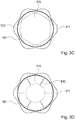
- FIG 3A is the sample carrier PT from the Fig. 1 and 2nd shown in an enlarged view from above.
- the sample carrier PT has a curvature that is periodically formed in the circumferential direction with a total of six curvatures WI that point inwards, that is to say to the sample carrier vertical axis RA.
- the total of six inward curvature WI corresponds to the number of possible rotations until a full rotation through 360 ° has been carried out. Accordingly, there are WI with six inward curvatures six measuring points MS arranged on the specimen PR. Since a minimum distance between a measuring point at which a hardness measurement is carried out and the outer edge of the specimen PR is required according to relevant standards, the in Fig. 1 and 2nd shown measuring device MV to be shifted towards the turntable vertical axis. This shift results in the area of a measuring point MS shown in dashed lines in Figure 3A .
- Figure 3B the PT sample holder is off Figure 3A shown in a partially sectioned side view.
- the sample body PR is placed in a recess AS on the top of the sample holder PT.
- On the underside of the sample holder PT is a cylindrical foot FU, by means of which the sample holder PT slips securely, can be rotated and is stored in the in Fig. 1 and Fig. 2 Shown AU of the turntable DT can be introduced.
- Ball bearing shown which is formed around the foot FU, may be provided.
- Fig. 3D shows, an area is formed between a smallest radius and a largest radius, the difference of which corresponds to the maximum displacement of the measuring device facing the turntable vertical axis, in which hardness measurements are carried out by means of the measuring device MV can.
- several measurements can be carried out per revolution of the turntable, that is to say per angular position of the sample carrier.
- the measuring device MV can perform measurements as a function of the rotation of the turntable DT at predetermined angles of rotation of the turntable DT. If the rotary finger and measuring device are offset, for example, by 180 °, measurements could be carried out after 170 °, 180 ° and after 190 ° rotation of the turntable about the turntable vertical axis.
- FIG 4A An actuating device SE is shown with a rotary finger (ST, DK) which comprises a pin ST and a rotary head DK.
- the rotating finger (ST, DK) is clamped against a spring FE within the adjusting device SE, so that the rotating finger (ST, DK) is pressed out of the adjusting device SE by means of a spring force of the spring FE.
- guide channel FK is provided, along which the rotary finger (ST, DK) is guided by means of a screw SR penetrating the guide channel FK.
- a nut MU is arranged on an extension of the pin ST protruding from the adjusting device SE. This nut MU engages in a thread on the pin ST so that it can be drawn further into the adjusting device SE against the spring force of the spring FE or the rotary finger (ST, DK) protrudes further from the adjusting device ST.
- the actuator SE is off Figure 4A shown in a top view. How Figure 4B can be seen, the guide channel is created so that the rotary finger (ST, DK) can not be rotated along its longitudinal axis.
- the Turret DK is rotatably mounted on pin ST and typically has a smaller radius than that in Figure 3A shown inward protrusion WI.
- Fig. 5 shows a measuring device MG which is firmly integrated in a laboratory device, with a measuring device MV, a turntable DT, an adjusting device SE, a control and computing unit RE for determining the hardness of specimen PR.
- a load device with an indenter protrudes onto a specimen in order to determine its hardness.
Landscapes
- Physics & Mathematics (AREA)
- Health & Medical Sciences (AREA)
- Life Sciences & Earth Sciences (AREA)
- Chemical & Material Sciences (AREA)
- Analytical Chemistry (AREA)
- Biochemistry (AREA)
- General Health & Medical Sciences (AREA)
- General Physics & Mathematics (AREA)
- Immunology (AREA)
- Pathology (AREA)
- Automatic Analysis And Handling Materials Therefor (AREA)
Applications Claiming Priority (1)
| Application Number | Priority Date | Filing Date | Title |
|---|---|---|---|
| DE102018125669.8A DE102018125669A1 (de) | 2018-10-16 | 2018-10-16 | Messgerät zur Bestimmung von Härtewerten an einem Probenkörper |
Publications (1)
| Publication Number | Publication Date |
|---|---|
| EP3647764A1 true EP3647764A1 (fr) | 2020-05-06 |
Family
ID=68172129
Family Applications (1)
| Application Number | Title | Priority Date | Filing Date |
|---|---|---|---|
| EP19201756.4A Withdrawn EP3647764A1 (fr) | 2018-10-16 | 2019-10-07 | Appareil de mesure permettant de déterminer des valeurs de dureté sur un corps d'échantillon |
Country Status (2)
| Country | Link |
|---|---|
| EP (1) | EP3647764A1 (fr) |
| DE (1) | DE102018125669A1 (fr) |
Cited By (5)
| Publication number | Priority date | Publication date | Assignee | Title |
|---|---|---|---|---|
| CN112986131A (zh) * | 2021-01-29 | 2021-06-18 | 南京航空航天大学 | 一种冰层粘附力测量装置 |
| WO2022159676A1 (fr) * | 2021-01-21 | 2022-07-28 | Illinois Tool Works Inc. | Système, procédé et appareil d'automatisation d'essai d'échantillon |
| CN115046843A (zh) * | 2022-05-19 | 2022-09-13 | 中国科学院精密测量科学与技术创新研究院 | 一种金属零长弹簧常温蠕变批量快速检测装置 |
| CN116735397A (zh) * | 2023-08-08 | 2023-09-12 | 泉州安磁电子有限公司 | 一种软磁铁氧体测试装置及其测试方法 |
| JP2024504369A (ja) * | 2021-01-21 | 2024-01-31 | イリノイ トゥール ワークス インコーポレイティド | 試料試験を自動化するシステム、方法、及び装置 |
Families Citing this family (1)
| Publication number | Priority date | Publication date | Assignee | Title |
|---|---|---|---|---|
| CN111751235B (zh) * | 2020-06-30 | 2023-02-07 | 中国航发动力股份有限公司 | 一种定度硬度块的工作台及其定度方法 |
Citations (5)
| Publication number | Priority date | Publication date | Assignee | Title |
|---|---|---|---|---|
| DE9318389U1 (de) | 1993-12-01 | 1995-03-30 | Heinrich Bareiss Prüfgerätebau GmbH, 89610 Oberdischingen | Elektronisches Prüfgerät zur Bestimmung der Härte |
| DE19751377C2 (de) | 1997-11-20 | 2000-12-07 | Heinrich Bareiss Pruefgeraeteb | Prüfvorrichtung |
| US20140293293A1 (en) * | 2011-02-10 | 2014-10-02 | Hysitron, Inc. | Nanomechanical testing system |
| US20170074763A1 (en) * | 2015-09-10 | 2017-03-16 | Mitutoyo Corporation | Hardness tester |
| DE202017102686U1 (de) | 2017-05-05 | 2017-05-15 | Bareiss Prüfgerätebau GmbH | Mehrfachmesskopf zur Bestimmung von Härtewerten an einem Probenkörper |
Family Cites Families (2)
| Publication number | Priority date | Publication date | Assignee | Title |
|---|---|---|---|---|
| US2640591A (en) * | 1950-01-10 | 1953-06-02 | Eaton Mfg Co | Automatic handling and hardness testing mechanism |
| EP1490698A1 (fr) * | 2002-03-11 | 2004-12-29 | Leco Corporation | Procede et systeme de chargement automatique d'echantillon et de creuset |
-
2018
- 2018-10-16 DE DE102018125669.8A patent/DE102018125669A1/de not_active Withdrawn
-
2019
- 2019-10-07 EP EP19201756.4A patent/EP3647764A1/fr not_active Withdrawn
Patent Citations (5)
| Publication number | Priority date | Publication date | Assignee | Title |
|---|---|---|---|---|
| DE9318389U1 (de) | 1993-12-01 | 1995-03-30 | Heinrich Bareiss Prüfgerätebau GmbH, 89610 Oberdischingen | Elektronisches Prüfgerät zur Bestimmung der Härte |
| DE19751377C2 (de) | 1997-11-20 | 2000-12-07 | Heinrich Bareiss Pruefgeraeteb | Prüfvorrichtung |
| US20140293293A1 (en) * | 2011-02-10 | 2014-10-02 | Hysitron, Inc. | Nanomechanical testing system |
| US20170074763A1 (en) * | 2015-09-10 | 2017-03-16 | Mitutoyo Corporation | Hardness tester |
| DE202017102686U1 (de) | 2017-05-05 | 2017-05-15 | Bareiss Prüfgerätebau GmbH | Mehrfachmesskopf zur Bestimmung von Härtewerten an einem Probenkörper |
Cited By (8)
| Publication number | Priority date | Publication date | Assignee | Title |
|---|---|---|---|---|
| WO2022159676A1 (fr) * | 2021-01-21 | 2022-07-28 | Illinois Tool Works Inc. | Système, procédé et appareil d'automatisation d'essai d'échantillon |
| JP2024504369A (ja) * | 2021-01-21 | 2024-01-31 | イリノイ トゥール ワークス インコーポレイティド | 試料試験を自動化するシステム、方法、及び装置 |
| US12241903B2 (en) | 2021-01-21 | 2025-03-04 | Illinois Tool Works Inc. | System, method, and apparatus for automating specimen testing |
| CN112986131A (zh) * | 2021-01-29 | 2021-06-18 | 南京航空航天大学 | 一种冰层粘附力测量装置 |
| CN115046843A (zh) * | 2022-05-19 | 2022-09-13 | 中国科学院精密测量科学与技术创新研究院 | 一种金属零长弹簧常温蠕变批量快速检测装置 |
| CN115046843B (zh) * | 2022-05-19 | 2023-08-29 | 中国科学院精密测量科学与技术创新研究院 | 一种金属零长弹簧常温蠕变批量快速检测装置 |
| CN116735397A (zh) * | 2023-08-08 | 2023-09-12 | 泉州安磁电子有限公司 | 一种软磁铁氧体测试装置及其测试方法 |
| CN116735397B (zh) * | 2023-08-08 | 2023-10-31 | 泉州安磁电子有限公司 | 一种软磁铁氧体测试装置及其测试方法 |
Also Published As
| Publication number | Publication date |
|---|---|
| DE102018125669A1 (de) | 2020-04-16 |
Similar Documents
| Publication | Publication Date | Title |
|---|---|---|
| DE102018125669A1 (de) | Messgerät zur Bestimmung von Härtewerten an einem Probenkörper | |
| DE2500788A1 (de) | Schnellwechsel-einspannvorrichtung fuer sich hin- und herbewegende werkzeugblaetter | |
| WO2008092752A1 (fr) | Outil d'alésage équilibré comprenant un mécanisme de serrage | |
| EP1971455B1 (fr) | Système d outillage pour un usinage par enlèvement de copeaux | |
| DE102007049372A1 (de) | Werkzeug zum Bohren und Ausdrehen mit einstellbaren Schneiden | |
| CH636193A5 (de) | Anzeigegeraet mit vorrichtung zum pruefen und messen von bohrungen. | |
| DE1548305C3 (de) | Gerät zur Bestimmung der Oberflächenrauhigkeit | |
| DE4418829C2 (de) | Verzahnungsprüfgerät | |
| DE10243690A1 (de) | Anordnung zum Nachschneiden von Scheibenwischerblättern | |
| EP0069060A2 (fr) | Support réglable pour instrument géodésique | |
| CH659612A5 (de) | Spannwerkzeug, insbesondere schraubzwinge. | |
| DE1623168A1 (de) | Dickenlehre fuer trockene UEberzuege | |
| DE9318389U1 (de) | Elektronisches Prüfgerät zur Bestimmung der Härte | |
| DE3425359C2 (de) | Prüfvorrichtung für stabförmige Bauteile, insbesondere Tragwerksabschnitt des Ingenieurbaus | |
| DE19702950C2 (de) | Verfahren und Vorrichtung zum Messen der Schichtdicke an zylindrischen Kleinteilen | |
| DE10019499B4 (de) | Beschriftungsverfahren für einen rotationssymmetrischen Signalträger und hiermit korrespondierende Beschriftungsvorrichtung | |
| DE2248535B2 (de) | Tisch zum pruefteilauflegen in geraeten zur kontrolle linearer groessen | |
| DE19854332A1 (de) | Testrotor für Auswuchtmaschinen | |
| DE3914775A1 (de) | Zentriereinrichtung fuer werkstoff-pruefgeraete | |
| DE10353781A1 (de) | Anordnung und Verfahren zur Bestimmung einer Kenngrösse für die Härte eines elastischen Prüflings | |
| DE379778C (de) | Pruefapparat, insbesondere zum Nachpruefen von Flaechen | |
| DE202024103108U1 (de) | Vorrichtung zur Begrenzung der Eingriffstiefe eines Zerspanungswerkzeugs | |
| DE102022131476A1 (de) | Verfahren zum Fixieren eines Anschlussmittels an eine Anschlussstelle | |
| DE2924347A1 (de) | Vorrichtung zum pruefen der haftfestigkeit von galvanischen oder chemisch abgeschiedenen metallschichten | |
| DE2033862C3 (de) | MeBvorrichtung zum Messen des Durchmessers sowie der Konzentrizität' einer ringförmigen Ausnehmung |
Legal Events
| Date | Code | Title | Description |
|---|---|---|---|
| PUAI | Public reference made under article 153(3) epc to a published international application that has entered the european phase |
Free format text: ORIGINAL CODE: 0009012 |
|
| STAA | Information on the status of an ep patent application or granted ep patent |
Free format text: STATUS: THE APPLICATION HAS BEEN PUBLISHED |
|
| AK | Designated contracting states |
Kind code of ref document: A1 Designated state(s): AL AT BE BG CH CY CZ DE DK EE ES FI FR GB GR HR HU IE IS IT LI LT LU LV MC MK MT NL NO PL PT RO RS SE SI SK SM TR |
|
| AX | Request for extension of the european patent |
Extension state: BA ME |
|
| STAA | Information on the status of an ep patent application or granted ep patent |
Free format text: STATUS: REQUEST FOR EXAMINATION WAS MADE |
|
| 17P | Request for examination filed |
Effective date: 20200907 |
|
| RBV | Designated contracting states (corrected) |
Designated state(s): AL AT BE BG CH CY CZ DE DK EE ES FI FR GB GR HR HU IE IS IT LI LT LU LV MC MK MT NL NO PL PT RO RS SE SI SK SM TR |
|
| STAA | Information on the status of an ep patent application or granted ep patent |
Free format text: STATUS: EXAMINATION IS IN PROGRESS |
|
| 17Q | First examination report despatched |
Effective date: 20201223 |
|
| GRAP | Despatch of communication of intention to grant a patent |
Free format text: ORIGINAL CODE: EPIDOSNIGR1 |
|
| STAA | Information on the status of an ep patent application or granted ep patent |
Free format text: STATUS: GRANT OF PATENT IS INTENDED |
|
| INTG | Intention to grant announced |
Effective date: 20210312 |
|
| STAA | Information on the status of an ep patent application or granted ep patent |
Free format text: STATUS: THE APPLICATION IS DEEMED TO BE WITHDRAWN |
|
| 18D | Application deemed to be withdrawn |
Effective date: 20210723 |