EP3647890A1 - Système d'assemblage et procédé pour faire fonctionner un système d'assemblage - Google Patents
Système d'assemblage et procédé pour faire fonctionner un système d'assemblage Download PDFInfo
- Publication number
- EP3647890A1 EP3647890A1 EP18203193.0A EP18203193A EP3647890A1 EP 3647890 A1 EP3647890 A1 EP 3647890A1 EP 18203193 A EP18203193 A EP 18203193A EP 3647890 A1 EP3647890 A1 EP 3647890A1
- Authority
- EP
- European Patent Office
- Prior art keywords
- assembly system
- assembly
- controller
- unit
- image
- Prior art date
- Legal status (The legal status is an assumption and is not a legal conclusion. Google has not performed a legal analysis and makes no representation as to the accuracy of the status listed.)
- Granted
Links
Images




Classifications
-
- G—PHYSICS
- G05—CONTROLLING; REGULATING
- G05B—CONTROL OR REGULATING SYSTEMS IN GENERAL; FUNCTIONAL ELEMENTS OF SUCH SYSTEMS; MONITORING OR TESTING ARRANGEMENTS FOR SUCH SYSTEMS OR ELEMENTS
- G05B19/00—Program-control systems
- G05B19/02—Program-control systems electric
- G05B19/04—Program control other than numerical control, i.e. in sequence controllers or logic controllers
- G05B19/048—Monitoring; Safety
-
- G—PHYSICS
- G05—CONTROLLING; REGULATING
- G05B—CONTROL OR REGULATING SYSTEMS IN GENERAL; FUNCTIONAL ELEMENTS OF SUCH SYSTEMS; MONITORING OR TESTING ARRANGEMENTS FOR SUCH SYSTEMS OR ELEMENTS
- G05B19/00—Program-control systems
- G05B19/02—Program-control systems electric
- G05B19/418—Total factory control, i.e. centrally controlling a plurality of machines, e.g. direct or distributed numerical control [DNC], flexible manufacturing systems [FMS], integrated manufacturing systems [IMS] or computer integrated manufacturing [CIM]
- G05B19/41805—Total factory control, i.e. centrally controlling a plurality of machines, e.g. direct or distributed numerical control [DNC], flexible manufacturing systems [FMS], integrated manufacturing systems [IMS] or computer integrated manufacturing [CIM] characterised by assembly
-
- G—PHYSICS
- G05—CONTROLLING; REGULATING
- G05B—CONTROL OR REGULATING SYSTEMS IN GENERAL; FUNCTIONAL ELEMENTS OF SUCH SYSTEMS; MONITORING OR TESTING ARRANGEMENTS FOR SUCH SYSTEMS OR ELEMENTS
- G05B2219/00—Program-control systems
- G05B2219/30—Nc systems
- G05B2219/31—From computer integrated manufacturing till monitoring
- G05B2219/31027—Computer assisted manual assembly CAA, display operation, tool, result
-
- G—PHYSICS
- G05—CONTROLLING; REGULATING
- G05B—CONTROL OR REGULATING SYSTEMS IN GENERAL; FUNCTIONAL ELEMENTS OF SUCH SYSTEMS; MONITORING OR TESTING ARRANGEMENTS FOR SUCH SYSTEMS OR ELEMENTS
- G05B2219/00—Program-control systems
- G05B2219/30—Nc systems
- G05B2219/31—From computer integrated manufacturing till monitoring
- G05B2219/31048—Project on workpiece, image of finished workpiece, info or a spot
-
- Y—GENERAL TAGGING OF NEW TECHNOLOGICAL DEVELOPMENTS; GENERAL TAGGING OF CROSS-SECTIONAL TECHNOLOGIES SPANNING OVER SEVERAL SECTIONS OF THE IPC; TECHNICAL SUBJECTS COVERED BY FORMER USPC CROSS-REFERENCE ART COLLECTIONS [XRACs] AND DIGESTS
- Y02—TECHNOLOGIES OR APPLICATIONS FOR MITIGATION OR ADAPTATION AGAINST CLIMATE CHANGE
- Y02P—CLIMATE CHANGE MITIGATION TECHNOLOGIES IN THE PRODUCTION OR PROCESSING OF GOODS
- Y02P90/00—Enabling technologies with a potential contribution to greenhouse gas [GHG] emissions mitigation
- Y02P90/02—Total factory control, e.g. smart factories, flexible manufacturing systems [FMS] or integrated manufacturing systems [IMS]
Definitions
- the present invention relates to an assembly system. Further, the invention relates to a method for operating such an assembly system.
- Assembly systems are sometimes used to manually assemble components into a product.
- Such assembly systems can comprise storage units such as bins for holding the components.
- a user may take the components from the storage units and assemble them on a work surface according to assembly instructions. It may be important to avoid an incorrect assembly of the components, as such an incorrect assembly could lead to a misfunction of the finished product.
- Document EP 2 957 973 A1 discloses a manual picking workstation with a plurality of component bins.
- the workstation tracks the order in which a user accesses the components bins using a light device capable of detecting a beam breakage when a component bin is accessed.
- an assembly system for assisting a user in assembling components into a product in accordance with assembly instructions.
- the assembly system comprises:
- the controller of the assembly system may determine the position or location of each storage unit by analyzing the image of the assembly system including the labels captured by the camera unit. That way, the controller obtains information relating to the components provided with the assembly system and can instruct the user assembling the components into the product accordingly. In particular, the location and presence of the components may be tracked using the labels.
- a more flexible assembly system is provided, as the assembly system can easily recognize the components contained in the storage units of the assembly systems, even when the components are changed. The assembly system is thus able to learn its own hardware configuration.
- the assembly system may be a work bench or work station.
- the storage units of the assembly system can include bins, containers and/or shelves. These storage units can be arranged next to one another such that the user can easily access each of the storage units when using the assembly system.
- the storage units can be open on a side facing the user to facilitate the picking of the components.
- the assembly system can include a work surface for assembling the components into the product. The assembly of the components into the product can be thought of as a manufacturing of the product.
- the components can include mechanical components (such as screws, washers or nails), electrical components (such as integrated circuits, diodes, batteries or switches), chemical components or the like.
- the components can also include tools necessary for the assembly of the product, such as screwdrivers, soldering irons or pipettes. If the user correctly follows the assembly instructions when assembling the components, he should obtain the correctly assembled product.
- the assembly instructions can be thought of as a recipe. They may include different steps indicating which component should be picked next and how it should be assembled with previously picked components.
- the machine-readable labels are visual representation of data indicating the content of the storage unit.
- the label of a storage unit allows an identification of the components stored in said storage unit.
- the term "content” here designates components that are actually present in the storage unit as well as components which are meant to be stored in the storage unit.
- Machine-readable means that a machine can be used to identify the components associated with the label.
- each component type has a predetermined unique label associated thereto.
- the labels may be one, two or three-dimensional codes, in particular barcodes or QR codes.
- the camera unit can be a two-dimensional and/or a three-dimensional camera. It can be removably attached to a holder of the assembly system. In particular, in the assembly system, the camera unit is orientated such as to capture images of at least the part of the assembly system which includes the labels.
- the placement (or position) of the camera unit does not have to be selected very accurately because the controller can detect the positions of the storage units independently of the exact placement of the camera unit.
- the camera unit may also be orientated towards a mirror that is attached to the assembly system.
- the camera unit can then acquire the image of the assembly system via the mirror.
- the mirror allows an increase of the distance between the camera unit and the assembly system. That way, the size of the portion of the assembly system that can be captured with the camera unit can be increased without having to move the camera unit further away from the assembly system.
- the image captured by the camera unit can be transmitted to the controller of the assembly system.
- the controller can be a CPU (central processing unit).
- the controller may analyze the image received by the camera unit in order to determine the positions of the respective storage units. In order to determine the position of each storage unit, the controller may recognize the positions of the labels of the assembly system. Since each label is associated with a storage unit, the controller can derive the positions of the storage units from the information about the position of the labels.
- the step of capturing the image of the assembly system including the labels performed by the camera unit and the step of determining the positions of the storage units based on this image by the controller may be part of a calibration of the assembly system.
- the controller may store the determined information about the positions of the storage units for later use.
- the assembly system further comprises a projector unit configured to project the assembly instructions onto the assembly system based on the positions of the at least two storage units determined by the controller.
- the assembly instructions can be projected in view of the positions of the storage units that were determined by the controller.
- the projection of the assembly instructions can include a projection of light onto the storage unit comprising the next component to be taken by the user.
- the projector unit may be removably attached to a holder of the assembly system.
- the projector unit is arranged on the assembly system such as to project the assembly instructions on the work surface, on the storage units and/or on a screen of the assembly system.
- Providing a removable projector unit is useful because it can be moved in accordance with the size and/or shape of the part of the assembly system that includes the storage units.
- the projector unit may be moved and/or rotated in order to select the surface of the assembly system onto which it projects the assembly instructions.
- the projector unit can have a reflection unit such as a mirror associated thereto.
- a reflection unit can be useful in guiding the assembly instructions projected by the projector unit into the right direction and/or for providing a larger projected image while retaining the light intensity and resolution of the projector unit.
- the resolution of the camera unit is set to a suitable resolution to reduce the load on the controller.
- the resolution of the projector unit can remain as high as possible.
- the assembly system may also include goggles (such as virtual reality goggles or augmented reality goggles) for the user to wear on his head.
- the projector unit may project the assembly instructions or other information directly onto the internal screen of the goggles.
- the assembly system may also comprise wearable computer glasses (also known as "smartglasses"), in which case the projector, which may be integrated into the wearable computer glasses, may be configured to project the assembly instructions or other information directly onto the user's retina.
- the assembly system further comprises machine-readable labels indicating predetermined points of the assembly system, wherein the controller is further configured to determine a size and/or shape of the assembly system based on the image captured by the camera unit.
- the controller can automatically and easily determine the size and/or shape of the assembly system based on the positions of the labels that are attached to the predetermined points of the assembly system.
- the positions of these labels can be extracted from the image of the assembly system including the labels captured by the camera unit.
- the labels indicating the predetermined points of the assembly system may be attached to these predetermined points.
- the predetermined points can include edges, corners, or the like of the assembly system.
- Each label indicating a predetermined point can include information indicating which predetermined point of the assembly system it is attached to. Said information can be machine-readable.
- the camera unit may also capture an image of the hand of the user when the hand is in the range covered by the camera unit.
- the controller is further configured to determine whether the components taken by the user from the storage units match the assembly instructions, based on the determined position of the hand and on the determined position of the storage units.
- the controller compares the component taken by the user with the component that the user is supposed to take according to the assembly instructions. If the user has taken the correct component as indicated by the assembly instructions, the controller determines that the taken component matches the assembly instructions. Otherwise, if the user has not taken the correct component as indicated by the assembly instructions, the controller determines that the taken component does not match the assembly instructions.
- the projector unit is further configured to project a confirmation signal and/or a warning signal onto the assembly system, based on the result of the determination whether the components taken by the user from the storage units match the assembly instructions.
- the projector unit can inform the user about whether he took the right components or not, thereby monitoring the processes performed by the user. Thereby, the user can get a confirmation of his actions (through the confirmation signal) and can continue to assemble the product. Alternatively, the user can receive a warning (through the warning signal) and interrupt the assembly of the product. In this case, the user can restart assembling a new product from scratch or correct his mistake. The correct assembly of the components can thereby be tracked all along the assembly process, thereby avoiding any incorrect component assemblies.
- the detection of the user's hand can be facilitated when the user is wearing a colored glove.
- the controller can recognize the presence of the hand when it detects an object having the same color or being in the same color range as the glove that is characterized by the glove color information. In particular, if the color of the glove is in high contrast with the surrounding environment, a correct measurement of the position of the glove can be ensured, even if the resolution of the camera unit is low.
- the glove color information can be determined from a plurality of color measurements performed by the controller.
- the controller can detect the color at different points of the image of the glove capture by the camera unit and take an average thereof to determine the glove color information.
- the camera unit may capture several subsequent images of the glove and the controller can determine the glove color information by averaging a color information of the glove from each image. Such an averaging of the color information may improve the accuracy of the glove detection.
- the controller may store the glove color information in an appropriate storage medium such as a server, a cloud or the like.
- the determination of the glove color information can be part of a calibration step of the assembly system.
- the user may be prompted to place his hand with the glove and/or the glove alone in front of the camera unit.
- the camera unit can then capture the image of the glove.
- the projector unit does not start projecting the assembly instructions until the glove color information has been determined. This is particularly useful in a case in which the user is required to wear gloves to avoid contamination of the product.
- the controller is further configured to:
- the controller may verify that all the components necessary to build the product are indeed present in the storage units of the assembly system. That way, the controller can automatically recognize missing components.
- the controller may determine which components are stored (or meant to be stored) in the storage units and compare these stored components with a list of components of the assembly instructions.
- the list of components of the assembly instructions can list all components necessary to assemble the product.
- the controller verifies that all components necessary to build the product are indeed present in the storage units during a configuration of the assembly system, for example before the user starts taking and assembling components.
- the projector unit is configured to project a missing component signal and/or the controller is configured to output the missing component signal if the controller determines that the components necessary for assembling the product are not all present in the assembly system.
- a missing component signal can be emitted.
- the missing component signal can inform the user about the missing component.
- the user may then add a storage unit with the component that was determined to be missing.
- the projector unit and the camera unit can perform a calibration in order to map their reference systems to one another. Such a calibration may be useful in precisely projecting the assembly instructions onto a selected part of the assembly system, for example onto the storage units.
- the calibration may include a projection of the line of light onto the surface of the assembly system, wherein the surface may include the labels.
- the projector unit swipes over the surface of the assembly system with the line of light while the camera unit captures an image of the assembly system including the line of light.
- the swiping (or scanning) can be performed horizontally and/or vertically.
- the controller can for example map the reference system of the camera unit to the reference system of the projector unit by matching various points of the assembly system to each other. These various points can form the predetermined points previously described and to which a label is assigned.
- the mapping of the two reference systems may compensate for shifts and/or misalignments of the projector unit and the camera unit.
- the mapping of the two reference systems may allow to translate the picking location of a component on the camera unit to the projector image.
- the projector unit is configured to project a light signal onto the storage unit to indicate the next component according to the assembly instructions.
- the projector unit may indicate by means of a projected light beam, which component the user should take next (next component according to the assembly instructions). The user can see a visual indication on the corresponding storage unit and easily know which component to take next. The assembly of the product may thus by facilitated by the present assembly system.
- each label allows a unique identification of the component contained in the storage unit onto which the label is attached.
- each label allows a unique identification of the component contained in the storage unit onto which the label is attached, a machine reading the label can uniquely identify the component contained in the storage unit.
- the assembly system further comprises:
- the controller checks whether the label storage unit already has label information corresponding to all the components necessary for constructing the product according to the new assembly instructions. If not, the label generation unit, which may be part of the controller or a separate entity, generates a label information for the components that do not have any label information stored in the label storage unit yet. In particular, no label information is created for the components which already have an associated label information stored in the label storage unit. Rather, for these components, the label information stored in the label storage unit are accessed by the controller and used.
- the label information can be a code defining the label for each component. Once the label information for each component necessary according to the assembly instructions has been generated, the label information can be used to print the corresponding physical labels, which are then attached to the respective storage units.
- a method for operating an assembly system that assists a user in assembling components into a product in accordance with assembly instructions.
- the method comprises:
- the method according to the second aspect can be implemented in the assembly system according to the first aspect or according to an embodiment thereof. Further possible implementations or alternative solutions of the invention also encompass combinations - that are not explicitly mentioned herein - of features described above or below with regard to the embodiments. The person skilled in the art may also add individual or isolated aspects and features to the most basic form of the invention.
- Fig. 1 shows a diagrammatic perspective view
- Fig. 2 shows a diagrammatic left side view of an assembly system 1.
- the assembly system 1 is used in a process of manufacturing a product 3 by assembling different components (not shown).
- the product 3 is assembled manually by a user 10 on a work surface 9 by assembling the components according to assembly instructions.
- the assembly system 1 comprises storage units 4, which are removably arranged next to one another in a picking area 12 of the assembly system 1.
- the storage units 4 are container bins, which are open on the side facing the user 10 to facilitate the taking out of components. Only one storage unit 4 is provided with a reference sign in Fig. 1 , however it is understood that all storage units shown in Fig. 1 have at least the same function of holding components.
- Each storage unit 4 has a machine-readable label 5 attached thereto, as will be described in greater detail below.
- Fig. 3 shows a diagrammatic perspective view of an example of four such storage units 4, which are labelled 4a - 4d for distinction.
- the storage unit 4a holds components 2a, here large screws.
- the storage unit 4b holds components 2b, here washers.
- the storage unit 4c holds components 2c, here pieces of plastic formed into a particular shape.
- the storage unit 4d holds components 2d, here small screws.
- each storage unit 4a - 4d holds components of different component types.
- the storage units 4a - 4d have labels 5a - 5d attached thereto, which are examples for the labels 5 of Fig. 1 .
- the labels 5a - 5d are QR codes which indicate the type of component provided in the storage units 4a - 4d to which they are attached (see Fig. 4 ).
- the labels 5a - 5d allow a unique identification of the component 2a - 2d in the storage unit 4a - 4d to which they are attached. For example, a machine reading the label 5a will be able to determine that the storage unit 4a to which the label 5a is attached is meant to hold large screws (component 2a).
- the labels 5a - 5d can be attached to the storage units 4a - 4d at manufacturing and/or packing of the storage units 4a - 4d, in particular before the storage units 4a - 4d are placed into the assembly system 1. Needless to say, it is also possible to attach the labels 5a - 5d to the storage units 4a - 4d after placing them in the assembly system 1.
- the assembly system 1 of Fig. 1 and 2 comprises a camera unit 6, a controller 7 and a projector unit 8.
- the camera unit 6 and the projector unit 8 may exchange data with the controller 7 through wired or wireless communication. More specifically, the camera unit 6 and the projector unit 8 may be connected to the controller 7 via a field network, such as an Ethernet or EtherCAT (registered trademark) network or the like.
- the assembly system 1 includes a mirror 11.
- the camera unit 6 is a 3D-camera for obtaining 3D-images of the monitored area 14.
- the camera unit 6 is removably attached to a work bench 30 of the assembly system 1 and orientated such as to monitor, e.g. via the mirror 11, the area 14 extending from the top of the storage units 4 of the work bench to a point in front of the work bench 30 (see Fig. 2 ).
- the projector unit 8 is used to project the assembly instructions onto parts of the assembly system 1.
- the projector unit 8 projects the assembly instructions towards the mirror 11, which reflects the assembly instructions onto a surface of the assembly system, as indicated by the light beams 13 irradiated by the projector unit 8 shown in Fig. 2 .
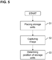
- the assembly system 1 can be operated according to the method of a first embodiment shown in Fig. 5 .
- step S1 of Fig. 5 the storage units 4 with the labels 5 are placed into the assembly system 1.
- step S2 the camera unit 6 acquires a 3D-image of at least a part of the assembly system 1 including the labels 5.
- This 3D-image is then analyzed by the controller 7 in step S3 in order to determine the positions of the storage units 4.
- the controller 7 performs an image analysis in order to detect the position of the labels 5 on the 3D-image and derives the positions of the storage units 4 from the positions of the labels 5.
- the positions of the storage units 4 can be represented by 3D-coordinates of the storage units 4.
- the steps S1 to S3 can be part of a calibration process of the assembly system 1 in which the assembly system 1 can autonomously determine its hardware-layout.
- the projector unit 8 projects the assembly instructions 23 onto the work surface 9 of the assembly system 1.
- Such assembly instructions 23 are for example shown in Fig. 12 and include an assembly image and an instruction text. The projection of the assembly instructions 23 facilitate the assembly of the product by the user 10.
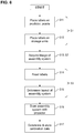
- the assembly system 1 can also be operated according to the method of a second embodiment shown in Fig. 6 .
- the method according to the second embodiment is a calibration method and can be thought of as an improved version of the method according to the first embodiment of Fig. 5 .
- step S11 of Fig. 6 further machine-readable labels 15a - 15f are attached to the assembly system 1.
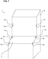
- Such further labels 15a - 15f are shown in Fig. 7 , which shows a further view of the assembly system 1.
- the further labels 15a - 15f are attached to the assembly system 1 at predetermined points 16 - 16f of the assembly system 1.
- the labels 15a - 15f are also QR codes.
- each further label 15a - 15f uniquely provides an information about the predetermined point 16a - 16f to which it is attached.
- the label 15a indicates that it is attached to the front left corner of the work surface 9.
- the label 15f indicates that it is attached to the right upper corner of the part of the assembly system 1 which comprises the storage units 4.
- the predetermined points 16a - 16f are points that are chosen in advance by the user 10 as judicious key points of the assembly system 1.
- step S12 of Fig. 6 the labels 5 are attached to the respective storage units 4, as described above in view of Fig. 1 to 4 .
- the steps S11 and S12 can be considered as part of step S1 of the method for operating the assembly system 1 according to the first embodiment ( Fig. 5 ).
- step S13 of Fig. 6 the camera unit 6 captures an image of the assembly system 1 including the labels 5, 15a - 15f.
- the step S13 corresponds to the previously described step S2 of the method for operating the assembly system 1 according to the first embodiment ( Fig. 5 ).
- Step S13 can be considered as a depth reference measurement in which a 3D-image of the assembly system 1 is acquired by the camera unit 6 and stored as a reference image for later use.
- step S14 of Fig. 6 the controller 7 detects and reads the labels 5, 15a - 15f. This means that the controller 7 extracts the information provided by the labels 5, 15a - 15f from the image acquired in step S13. Further, the controller 7 determines the 3D-coordinates of the labels 5, 15a - 15f and stores these in a storage medium.
- the controller 7 determines a layout of the assembly system 1 in step S15 of Fig. 6 . In detail, the controller 7 determines the size and shape of the work bench 30, including the size and shape of the work surface 9.
- the controller 7 may initiate a depth reference measurement of the assembly system 1 with the camera unit 6.
- the steps S14 and S15 can be part of step S3 of the method for operating the assembly system 1 according to the first embodiment ( Fig. 5 ).
- step S16 of Fig. 6 the projector unit 8 scans (i.e. irradiates light in a scanning manner onto) the assembly system 1 in order to map the reference systems of the projector unit 8 and of the camera unit 6 onto each other.
- images captured by the camera unit 6 are slightly distorted.
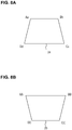
- the rectangular work surface 9 may look trapezoidal on an image 25 captured by the camera unit 6 (see Fig. 8B ).
- the image 24 projected by the projector unit 8 onto the work surface 9 is also distorted.
- said image 24 has a mirrored trapezium shape as compared to the image 25 of the camera unit 6 (see Fig. 8A ).
- the projector unit 8 scans the assembly system vertically and horizontally with a line of light. While the scans are being performed, the camera unit 6 captures images of the line. The controller 7 then finds the coordinates of points A, B, C and D (corresponding to the corners of the work surface 9) in the reference system of the projector unit 8 (coordinates Aa, Bb, Cc and Dd in Fig. 8A ) and in the reference system of the camera unit 6 (coordinates AA, BB, CC and DD in Fig. 8B ). The controller 7 then determines a relationship between the two reference systems with which the distortions between the two reference systems can be compensated.
- the steps S11 to S17 of Fig. 6 can be considered as calibration steps performed before starting an assembly of components 2a - 2d.
- the controller 7 determines calibration data based on the layout of the assembly system 1 determined in step S15 and based on the mapping of the reference systems of the projector unit 8 and of the camera unit 6 of step S16.
- This calibration data is stored in a storage medium, such as a server, cloud or other suitable storage device, for use when assembling the components 2a - 2d into the product 3. More specifically, the calibration data may include transformation parameters for a suitable coordinate transformation that ensures that the image projected by the projector 8 can be imaged by the camera unit 6 without distortion.
- the assembly system 1 can also be operated according to the method of a third embodiment shown in Fig. 9 .
- the camera unit 6 acquires a color and depth image of the assembly system 1.
- the color and depth image corresponds to a 3D color image of the assembly system 1.
- step S5 of Fig. 9 the controller 7 determines the 3D-coordinates of a glove 19 worn by the user 10 on his hand 18.
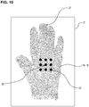
- a glove 19 is shown in Fig. 10 .
- Fig. 10 shows an image 17 of the glove 19 acquired during calibration by the camera unit 6.
- the controller 7 performs nine color measurements at nine measurement points 20 of the glove image 17 and averages the color information obtained during these color measurements to obtain glove color information.
- the glove color information is stored in a storage medium.
- step S5 of Fig. 9 in order to determine the position of the glove 19, the controller searches the image of the assembly system 1 obtained in step S4 for an object that is of the same color as the glove 19 and has the same glove color information. When such an object is found, the controller 7 determines that it is a glove 19 and calculates its position. In particular, the position of the glove 19 is determined using a hand center 22 as a reference, while a hand top 21 is used to determine which component 2a - 2d is taken by the user 10.
- step S6 of Fig. 9 the controller 7 compares the position of the glove 19 determined in step S5 with the assembly instructions 23. This comparison corresponds to a verification if the component 2a - 2d taken out of the storage unit 4 by the user 10 is indeed the correct next component 2a - 2d according to the assembly instructions 23.
- the controller 7 may be configured to decide that a component has been retrieved from one of the storage units 4 if (a) the glove 19 makes a reciprocating movement, in which it first approaches the storage unit 4 and then recedes from that storage unit 4, and (b) the distance between a reference position of the storage unit 4 (e.g. the position of the corresponding label 5 and the glove 19 at the point of reciprocation (i.e. the point where the movement direction of the glove 19 is reversed or changed) is smaller than a threshold distance.
- the controller 7 may also take into account other factors, such as the movement speed of the glove 19, the orientation of the glove 19, or whether the glove 19 remains for a minimum period of time (e.g. 0.3 sec) at the point of reciprocation.
- step S7 of Fig. 9 the controller 7 verifies whether the component 2a - 2d taken out of the storage unit 4 by the user 10 is indeed the correct next component 2a - 2d according to the assembly instructions 23. If the controller 7 determines that the component 2a - 2d taken out of the storage unit 4 by the user 10 is indeed the correct next component 2a - 2d according to the assembly instructions 23 ("YES" in step S7), the projector unit 8 emits a confirmation signal in step S8.
- step S7 determines that the component 2a - 2d taken out of the storage unit 4 by the user 10 is not the correct next component 2a - 2d according to the assembly instructions 23 ("NO" in step S7), the projector unit 8 emits a warning signal in step S9.
- the projector unit 8 projects a green light onto the work surface 9 or another suitable surface of the assembly system 1. Furthermore, to emit the warning signal (step S9), the projector unit 8 projects a red light onto the work surface 9 or another suitable surface of the assembly system 1. That way, the user 10 can easily visualize whether he took the correct component 2a - 2d in view of the assembly instructions 23 or not.
- step S10 the data about the match or mismatch determined in step S7 is stored in a cloud.
- the cloud can be accessed by an overlying control system.
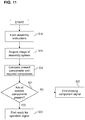
- the assembly system 1 can also be operated according to the method of a fourth embodiment shown in Fig. 11 .
- the assembly instructions 23 are obtained from the overlaying control system.
- a color and depth image (or 3D color image) of the assembly system 1 is obtained by the camera unit 6.
- step S20 of Fig. 11 the controller 7 detects the labels 5, 5a - 5d of the assembly system 1 and derives the components 2a - 2d that are present in the assembly system 1 therefrom. The controller 7 then compares the components 2a - 2d that were determined to be present with a list of required components extracted from the assembly instructions 23.
- step S21 of Fig. 11 the controller 7 determines whether all components 2a - 2d which are needed to assemble the product 3 are present in the assembly system. If the controller 7 determines that at least one component 2a - 2d is missing ("NO" in step S21), the controller emits a missing component signal at step S22.
- the missing component signal indicates which component 2a - 2d is missing and is emitted to the user 10. Thereby, the user 10 is informed about the missing component 2a - 2d and can add said component 2a - 2d to the assembly system 1.
- the missing component signal may be any signal that is suitable to alert the user 10 to the fact that a component 2a - 2d is missing.
- the controller 7 determines that all necessary components 2a - 2d are provided (“YES” in step S21), the controller emits a "ready for operation” signal at step S23. This "ready for operation” indicates that the user 10 can start assembling the components 2a - 2d to form the product 3.
- the storage units 4 can have different sizes, which the controller 7 is able to recognize by analyzing the position of the labels 5, 5a - 5d.
- the assembly system may be capable of generating its own labels using a label generation unit, for example.
- the projection of the assembly instructions by the projection unit can include a projection of light onto the storage unit comprising the next component to be taken by the user.
Landscapes
- Engineering & Computer Science (AREA)
- Physics & Mathematics (AREA)
- General Physics & Mathematics (AREA)
- Automation & Control Theory (AREA)
- General Engineering & Computer Science (AREA)
- Manufacturing & Machinery (AREA)
- Quality & Reliability (AREA)
- User Interface Of Digital Computer (AREA)
Priority Applications (1)
| Application Number | Priority Date | Filing Date | Title |
|---|---|---|---|
| EP18203193.0A EP3647890B1 (fr) | 2018-10-29 | 2018-10-29 | Système d'assemblage et procédé pour faire fonctionner un système d'assemblage |
Applications Claiming Priority (1)
| Application Number | Priority Date | Filing Date | Title |
|---|---|---|---|
| EP18203193.0A EP3647890B1 (fr) | 2018-10-29 | 2018-10-29 | Système d'assemblage et procédé pour faire fonctionner un système d'assemblage |
Publications (2)
| Publication Number | Publication Date |
|---|---|
| EP3647890A1 true EP3647890A1 (fr) | 2020-05-06 |
| EP3647890B1 EP3647890B1 (fr) | 2022-03-16 |
Family
ID=64100597
Family Applications (1)
| Application Number | Title | Priority Date | Filing Date |
|---|---|---|---|
| EP18203193.0A Not-in-force EP3647890B1 (fr) | 2018-10-29 | 2018-10-29 | Système d'assemblage et procédé pour faire fonctionner un système d'assemblage |
Country Status (1)
| Country | Link |
|---|---|
| EP (1) | EP3647890B1 (fr) |
Cited By (1)
| Publication number | Priority date | Publication date | Assignee | Title |
|---|---|---|---|---|
| EP3961327A1 (fr) | 2020-08-27 | 2022-03-02 | Omron Europe B.V. | Procédé et dispositif d'aide à l'assemblage |
Families Citing this family (1)
| Publication number | Priority date | Publication date | Assignee | Title |
|---|---|---|---|---|
| EP4488779A1 (fr) | 2023-07-07 | 2025-01-08 | Omron Corporation | Aide au montage de composants basée sur une caméra |
Citations (3)
| Publication number | Priority date | Publication date | Assignee | Title |
|---|---|---|---|---|
| WO2007044558A2 (fr) * | 2005-10-07 | 2007-04-19 | Ops Solutions Llc | Systeme d'ensemble guide par la lumiere |
| US20130325155A1 (en) * | 2011-02-11 | 2013-12-05 | Ops Solutions Llc | Light guided assembly system and method |
| EP2957973A1 (fr) | 2014-05-30 | 2015-12-23 | Fives Inc. | Surveillance de position à base de lumière d'une station de travail |
Family Cites Families (2)
| Publication number | Priority date | Publication date | Assignee | Title |
|---|---|---|---|---|
| EP2745999A1 (fr) * | 2011-08-19 | 2014-06-25 | Kabushiki Kaisha Yaskawa Denki | Système de robot, dispositif de commande de robot, main de robot et procédé de commande de robot |
| CN106465573B (zh) * | 2014-05-13 | 2019-05-07 | 艾塔尔公司 | 电子元件安装系统 |
-
2018
- 2018-10-29 EP EP18203193.0A patent/EP3647890B1/fr not_active Not-in-force
Patent Citations (4)
| Publication number | Priority date | Publication date | Assignee | Title |
|---|---|---|---|---|
| WO2007044558A2 (fr) * | 2005-10-07 | 2007-04-19 | Ops Solutions Llc | Systeme d'ensemble guide par la lumiere |
| US7515981B2 (en) | 2005-10-07 | 2009-04-07 | Ops Solutions Llc | Light guided assembly system |
| US20130325155A1 (en) * | 2011-02-11 | 2013-12-05 | Ops Solutions Llc | Light guided assembly system and method |
| EP2957973A1 (fr) | 2014-05-30 | 2015-12-23 | Fives Inc. | Surveillance de position à base de lumière d'une station de travail |
Cited By (2)
| Publication number | Priority date | Publication date | Assignee | Title |
|---|---|---|---|---|
| EP3961327A1 (fr) | 2020-08-27 | 2022-03-02 | Omron Europe B.V. | Procédé et dispositif d'aide à l'assemblage |
| EP3961330A1 (fr) | 2020-08-27 | 2022-03-02 | Omron Europe B.V. | Appareil d'assistance pour assemblage et procédé |
Also Published As
| Publication number | Publication date |
|---|---|
| EP3647890B1 (fr) | 2022-03-16 |
Similar Documents
| Publication | Publication Date | Title |
|---|---|---|
| US10664675B2 (en) | Code recognition device | |
| US8559704B2 (en) | Three-dimensional vision sensor | |
| US8146814B2 (en) | Remote crane bar code system | |
| US11170244B2 (en) | Device and method for analyzing state of manual work by worker, and work analysis program | |
| WO2019177539A1 (fr) | Procédé d'inspection visuelle et appareil associé | |
| EP2774079B1 (fr) | Procédé d'acquisition d'image | |
| JP2012215394A (ja) | 三次元計測装置および三次元計測方法 | |
| JP2008506953A (ja) | 機械視覚のための方法及び装置 | |
| JP2008235504A (ja) | 組立品検査装置 | |
| CN114612417B (zh) | 印刷电路板的缺陷定位设备、定位方法及光学检测系统 | |
| US20090084855A1 (en) | Methods and Apparatus for Directing Bar Code Positioning for Imaging Scanning | |
| CN108010011B (zh) | 一种帮助确认目标物体上的目标区域的装置及包括该装置的设备 | |
| US12159368B2 (en) | Systems and methods for automated image-based auditing of equipment cabinets | |
| EP3647890B1 (fr) | Système d'assemblage et procédé pour faire fonctionner un système d'assemblage | |
| CN112529856A (zh) | 确定操作对象位置的方法、机器人和自动化系统 | |
| JP2004259114A (ja) | 物体識別方法および物体識別装置、並びに物体識別プログラム | |
| US20250098942A1 (en) | Systems, devices, and methods for calibrating a medical camera | |
| US11717970B2 (en) | Controller, control method using controller, and control system | |
| CN111199533B (zh) | 图像处理装置 | |
| CN117532603B (zh) | 一种移动机器人上下料快速定位方法、系统及装置 | |
| JP2014035635A (ja) | 対象物管理システム | |
| JP2003156311A (ja) | アライメントマークの検出、登録方法及び装置 | |
| US11145066B2 (en) | Parcel recognition device, parcel sorting system, and parcel recognition method | |
| CN118392029B (zh) | 一种基于ar的制孔锪窝检测方法、系统、设备及介质 | |
| JP7304992B2 (ja) | コード認識装置 |
Legal Events
| Date | Code | Title | Description |
|---|---|---|---|
| PUAI | Public reference made under article 153(3) epc to a published international application that has entered the european phase |
Free format text: ORIGINAL CODE: 0009012 |
|
| STAA | Information on the status of an ep patent application or granted ep patent |
Free format text: STATUS: REQUEST FOR EXAMINATION WAS MADE |
|
| 17P | Request for examination filed |
Effective date: 20181029 |
|
| AK | Designated contracting states |
Kind code of ref document: A1 Designated state(s): AL AT BE BG CH CY CZ DE DK EE ES FI FR GB GR HR HU IE IS IT LI LT LU LV MC MK MT NL NO PL PT RO RS SE SI SK SM TR |
|
| AX | Request for extension of the european patent |
Extension state: BA ME |
|
| STAA | Information on the status of an ep patent application or granted ep patent |
Free format text: STATUS: EXAMINATION IS IN PROGRESS |
|
| 17Q | First examination report despatched |
Effective date: 20201026 |
|
| GRAP | Despatch of communication of intention to grant a patent |
Free format text: ORIGINAL CODE: EPIDOSNIGR1 |
|
| STAA | Information on the status of an ep patent application or granted ep patent |
Free format text: STATUS: GRANT OF PATENT IS INTENDED |
|
| INTG | Intention to grant announced |
Effective date: 20220110 |
|
| GRAS | Grant fee paid |
Free format text: ORIGINAL CODE: EPIDOSNIGR3 |
|
| GRAA | (expected) grant |
Free format text: ORIGINAL CODE: 0009210 |
|
| STAA | Information on the status of an ep patent application or granted ep patent |
Free format text: STATUS: THE PATENT HAS BEEN GRANTED |
|
| AK | Designated contracting states |
Kind code of ref document: B1 Designated state(s): AL AT BE BG CH CY CZ DE DK EE ES FI FR GB GR HR HU IE IS IT LI LT LU LV MC MK MT NL NO PL PT RO RS SE SI SK SM TR |
|
| REG | Reference to a national code |
Ref country code: GB Ref legal event code: FG4D |
|
| REG | Reference to a national code |
Ref country code: CH Ref legal event code: EP Ref country code: DE Ref legal event code: R096 Ref document number: 602018032248 Country of ref document: DE |
|
| REG | Reference to a national code |
Ref country code: IE Ref legal event code: FG4D |
|
| REG | Reference to a national code |
Ref country code: AT Ref legal event code: REF Ref document number: 1476335 Country of ref document: AT Kind code of ref document: T Effective date: 20220415 |
|
| REG | Reference to a national code |
Ref country code: LT Ref legal event code: MG9D |
|
| REG | Reference to a national code |
Ref country code: NL Ref legal event code: MP Effective date: 20220316 |
|
| PG25 | Lapsed in a contracting state [announced via postgrant information from national office to epo] |
Ref country code: SE Free format text: LAPSE BECAUSE OF FAILURE TO SUBMIT A TRANSLATION OF THE DESCRIPTION OR TO PAY THE FEE WITHIN THE PRESCRIBED TIME-LIMIT Effective date: 20220316 Ref country code: RS Free format text: LAPSE BECAUSE OF FAILURE TO SUBMIT A TRANSLATION OF THE DESCRIPTION OR TO PAY THE FEE WITHIN THE PRESCRIBED TIME-LIMIT Effective date: 20220316 Ref country code: NO Free format text: LAPSE BECAUSE OF FAILURE TO SUBMIT A TRANSLATION OF THE DESCRIPTION OR TO PAY THE FEE WITHIN THE PRESCRIBED TIME-LIMIT Effective date: 20220616 Ref country code: LT Free format text: LAPSE BECAUSE OF FAILURE TO SUBMIT A TRANSLATION OF THE DESCRIPTION OR TO PAY THE FEE WITHIN THE PRESCRIBED TIME-LIMIT Effective date: 20220316 Ref country code: HR Free format text: LAPSE BECAUSE OF FAILURE TO SUBMIT A TRANSLATION OF THE DESCRIPTION OR TO PAY THE FEE WITHIN THE PRESCRIBED TIME-LIMIT Effective date: 20220316 Ref country code: BG Free format text: LAPSE BECAUSE OF FAILURE TO SUBMIT A TRANSLATION OF THE DESCRIPTION OR TO PAY THE FEE WITHIN THE PRESCRIBED TIME-LIMIT Effective date: 20220616 |
|
| REG | Reference to a national code |
Ref country code: AT Ref legal event code: MK05 Ref document number: 1476335 Country of ref document: AT Kind code of ref document: T Effective date: 20220316 |
|
| PG25 | Lapsed in a contracting state [announced via postgrant information from national office to epo] |
Ref country code: LV Free format text: LAPSE BECAUSE OF FAILURE TO SUBMIT A TRANSLATION OF THE DESCRIPTION OR TO PAY THE FEE WITHIN THE PRESCRIBED TIME-LIMIT Effective date: 20220316 Ref country code: GR Free format text: LAPSE BECAUSE OF FAILURE TO SUBMIT A TRANSLATION OF THE DESCRIPTION OR TO PAY THE FEE WITHIN THE PRESCRIBED TIME-LIMIT Effective date: 20220617 Ref country code: FI Free format text: LAPSE BECAUSE OF FAILURE TO SUBMIT A TRANSLATION OF THE DESCRIPTION OR TO PAY THE FEE WITHIN THE PRESCRIBED TIME-LIMIT Effective date: 20220316 |
|
| PG25 | Lapsed in a contracting state [announced via postgrant information from national office to epo] |
Ref country code: NL Free format text: LAPSE BECAUSE OF FAILURE TO SUBMIT A TRANSLATION OF THE DESCRIPTION OR TO PAY THE FEE WITHIN THE PRESCRIBED TIME-LIMIT Effective date: 20220316 |
|
| PG25 | Lapsed in a contracting state [announced via postgrant information from national office to epo] |
Ref country code: SM Free format text: LAPSE BECAUSE OF FAILURE TO SUBMIT A TRANSLATION OF THE DESCRIPTION OR TO PAY THE FEE WITHIN THE PRESCRIBED TIME-LIMIT Effective date: 20220316 Ref country code: SK Free format text: LAPSE BECAUSE OF FAILURE TO SUBMIT A TRANSLATION OF THE DESCRIPTION OR TO PAY THE FEE WITHIN THE PRESCRIBED TIME-LIMIT Effective date: 20220316 Ref country code: RO Free format text: LAPSE BECAUSE OF FAILURE TO SUBMIT A TRANSLATION OF THE DESCRIPTION OR TO PAY THE FEE WITHIN THE PRESCRIBED TIME-LIMIT Effective date: 20220316 Ref country code: PT Free format text: LAPSE BECAUSE OF FAILURE TO SUBMIT A TRANSLATION OF THE DESCRIPTION OR TO PAY THE FEE WITHIN THE PRESCRIBED TIME-LIMIT Effective date: 20220718 Ref country code: ES Free format text: LAPSE BECAUSE OF FAILURE TO SUBMIT A TRANSLATION OF THE DESCRIPTION OR TO PAY THE FEE WITHIN THE PRESCRIBED TIME-LIMIT Effective date: 20220316 Ref country code: EE Free format text: LAPSE BECAUSE OF FAILURE TO SUBMIT A TRANSLATION OF THE DESCRIPTION OR TO PAY THE FEE WITHIN THE PRESCRIBED TIME-LIMIT Effective date: 20220316 Ref country code: CZ Free format text: LAPSE BECAUSE OF FAILURE TO SUBMIT A TRANSLATION OF THE DESCRIPTION OR TO PAY THE FEE WITHIN THE PRESCRIBED TIME-LIMIT Effective date: 20220316 Ref country code: AT Free format text: LAPSE BECAUSE OF FAILURE TO SUBMIT A TRANSLATION OF THE DESCRIPTION OR TO PAY THE FEE WITHIN THE PRESCRIBED TIME-LIMIT Effective date: 20220316 |
|
| PG25 | Lapsed in a contracting state [announced via postgrant information from national office to epo] |
Ref country code: PL Free format text: LAPSE BECAUSE OF FAILURE TO SUBMIT A TRANSLATION OF THE DESCRIPTION OR TO PAY THE FEE WITHIN THE PRESCRIBED TIME-LIMIT Effective date: 20220316 Ref country code: IS Free format text: LAPSE BECAUSE OF FAILURE TO SUBMIT A TRANSLATION OF THE DESCRIPTION OR TO PAY THE FEE WITHIN THE PRESCRIBED TIME-LIMIT Effective date: 20220716 Ref country code: AL Free format text: LAPSE BECAUSE OF FAILURE TO SUBMIT A TRANSLATION OF THE DESCRIPTION OR TO PAY THE FEE WITHIN THE PRESCRIBED TIME-LIMIT Effective date: 20220316 |
|
| REG | Reference to a national code |
Ref country code: DE Ref legal event code: R097 Ref document number: 602018032248 Country of ref document: DE |
|
| PLBE | No opposition filed within time limit |
Free format text: ORIGINAL CODE: 0009261 |
|
| STAA | Information on the status of an ep patent application or granted ep patent |
Free format text: STATUS: NO OPPOSITION FILED WITHIN TIME LIMIT |
|
| PG25 | Lapsed in a contracting state [announced via postgrant information from national office to epo] |
Ref country code: DK Free format text: LAPSE BECAUSE OF FAILURE TO SUBMIT A TRANSLATION OF THE DESCRIPTION OR TO PAY THE FEE WITHIN THE PRESCRIBED TIME-LIMIT Effective date: 20220316 |
|
| 26N | No opposition filed |
Effective date: 20221219 |
|
| PG25 | Lapsed in a contracting state [announced via postgrant information from national office to epo] |
Ref country code: SI Free format text: LAPSE BECAUSE OF FAILURE TO SUBMIT A TRANSLATION OF THE DESCRIPTION OR TO PAY THE FEE WITHIN THE PRESCRIBED TIME-LIMIT Effective date: 20220316 |
|
| PG25 | Lapsed in a contracting state [announced via postgrant information from national office to epo] |
Ref country code: MC Free format text: LAPSE BECAUSE OF FAILURE TO SUBMIT A TRANSLATION OF THE DESCRIPTION OR TO PAY THE FEE WITHIN THE PRESCRIBED TIME-LIMIT Effective date: 20220316 |
|
| REG | Reference to a national code |
Ref country code: CH Ref legal event code: PL |
|
| REG | Reference to a national code |
Ref country code: BE Ref legal event code: MM Effective date: 20221031 |
|
| GBPC | Gb: european patent ceased through non-payment of renewal fee |
Effective date: 20221029 |
|
| PG25 | Lapsed in a contracting state [announced via postgrant information from national office to epo] |
Ref country code: LU Free format text: LAPSE BECAUSE OF NON-PAYMENT OF DUE FEES Effective date: 20221029 |
|
| PG25 | Lapsed in a contracting state [announced via postgrant information from national office to epo] |
Ref country code: LI Free format text: LAPSE BECAUSE OF NON-PAYMENT OF DUE FEES Effective date: 20221031 Ref country code: IT Free format text: LAPSE BECAUSE OF FAILURE TO SUBMIT A TRANSLATION OF THE DESCRIPTION OR TO PAY THE FEE WITHIN THE PRESCRIBED TIME-LIMIT Effective date: 20220316 Ref country code: FR Free format text: LAPSE BECAUSE OF NON-PAYMENT OF DUE FEES Effective date: 20221031 Ref country code: CH Free format text: LAPSE BECAUSE OF NON-PAYMENT OF DUE FEES Effective date: 20221031 |
|
| PG25 | Lapsed in a contracting state [announced via postgrant information from national office to epo] |
Ref country code: BE Free format text: LAPSE BECAUSE OF NON-PAYMENT OF DUE FEES Effective date: 20221031 |
|
| PG25 | Lapsed in a contracting state [announced via postgrant information from national office to epo] |
Ref country code: IE Free format text: LAPSE BECAUSE OF NON-PAYMENT OF DUE FEES Effective date: 20221029 Ref country code: GB Free format text: LAPSE BECAUSE OF NON-PAYMENT OF DUE FEES Effective date: 20221029 |
|
| PGFP | Annual fee paid to national office [announced via postgrant information from national office to epo] |
Ref country code: DE Payment date: 20230906 Year of fee payment: 6 |
|
| PG25 | Lapsed in a contracting state [announced via postgrant information from national office to epo] |
Ref country code: HU Free format text: LAPSE BECAUSE OF FAILURE TO SUBMIT A TRANSLATION OF THE DESCRIPTION OR TO PAY THE FEE WITHIN THE PRESCRIBED TIME-LIMIT; INVALID AB INITIO Effective date: 20181029 |
|
| PG25 | Lapsed in a contracting state [announced via postgrant information from national office to epo] |
Ref country code: CY Free format text: LAPSE BECAUSE OF FAILURE TO SUBMIT A TRANSLATION OF THE DESCRIPTION OR TO PAY THE FEE WITHIN THE PRESCRIBED TIME-LIMIT Effective date: 20220316 |
|
| PG25 | Lapsed in a contracting state [announced via postgrant information from national office to epo] |
Ref country code: MK Free format text: LAPSE BECAUSE OF FAILURE TO SUBMIT A TRANSLATION OF THE DESCRIPTION OR TO PAY THE FEE WITHIN THE PRESCRIBED TIME-LIMIT Effective date: 20220316 |
|
| PG25 | Lapsed in a contracting state [announced via postgrant information from national office to epo] |
Ref country code: TR Free format text: LAPSE BECAUSE OF FAILURE TO SUBMIT A TRANSLATION OF THE DESCRIPTION OR TO PAY THE FEE WITHIN THE PRESCRIBED TIME-LIMIT Effective date: 20220316 |
|
| PG25 | Lapsed in a contracting state [announced via postgrant information from national office to epo] |
Ref country code: MT Free format text: LAPSE BECAUSE OF FAILURE TO SUBMIT A TRANSLATION OF THE DESCRIPTION OR TO PAY THE FEE WITHIN THE PRESCRIBED TIME-LIMIT Effective date: 20220316 |
|
| REG | Reference to a national code |
Ref country code: DE Ref legal event code: R119 Ref document number: 602018032248 Country of ref document: DE |
|
| PG25 | Lapsed in a contracting state [announced via postgrant information from national office to epo] |
Ref country code: DE Free format text: LAPSE BECAUSE OF NON-PAYMENT OF DUE FEES Effective date: 20250501 |