EP3648540B1 - Mappage de flux de qualité de service à des porteuses radio - Google Patents
Mappage de flux de qualité de service à des porteuses radio Download PDFInfo
- Publication number
- EP3648540B1 EP3648540B1 EP18203354.8A EP18203354A EP3648540B1 EP 3648540 B1 EP3648540 B1 EP 3648540B1 EP 18203354 A EP18203354 A EP 18203354A EP 3648540 B1 EP3648540 B1 EP 3648540B1
- Authority
- EP
- European Patent Office
- Prior art keywords
- access node
- qos flow
- terminal device
- message
- new qos
- Prior art date
- Legal status (The legal status is an assumption and is not a legal conclusion. Google has not performed a legal analysis and makes no representation as to the accuracy of the status listed.)
- Active
Links
Images


Classifications
-
- H—ELECTRICITY
- H04—ELECTRIC COMMUNICATION TECHNIQUE
- H04W—WIRELESS COMMUNICATION NETWORKS
- H04W76/00—Connection management
- H04W76/10—Connection setup
- H04W76/15—Setup of multiple wireless link connections
-
- H—ELECTRICITY
- H04—ELECTRIC COMMUNICATION TECHNIQUE
- H04W—WIRELESS COMMUNICATION NETWORKS
- H04W28/00—Network traffic management; Network resource management
- H04W28/02—Traffic management, e.g. flow control or congestion control
- H04W28/0268—Traffic management, e.g. flow control or congestion control using specific QoS parameters for wireless networks, e.g. QoS class identifier [QCI] or guaranteed bit rate [GBR]
-
- H—ELECTRICITY
- H04—ELECTRIC COMMUNICATION TECHNIQUE
- H04W—WIRELESS COMMUNICATION NETWORKS
- H04W28/00—Network traffic management; Network resource management
- H04W28/02—Traffic management, e.g. flow control or congestion control
- H04W28/0252—Traffic management, e.g. flow control or congestion control per individual bearer or channel
- H04W28/0263—Traffic management, e.g. flow control or congestion control per individual bearer or channel involving mapping traffic to individual bearers or channels, e.g. traffic flow template [TFT]
-
- H—ELECTRICITY
- H04—ELECTRIC COMMUNICATION TECHNIQUE
- H04W—WIRELESS COMMUNICATION NETWORKS
- H04W40/00—Communication routing or communication path finding
- H04W40/34—Modification of an existing route
Definitions
- Various embodiments described herein relate to the field of wireless communications and, particularly, to mapping between quality of service (QoS) flows and radio bearers.
- QoS quality of service
- a protocol data unit (PDU) session is established between a user equipment (UE) and a core network of the cellular communication system, e.g. a user plane function (UPF) of the core network.
- QoS Quality of service flows may then be established within the PDU session for transfer of data, and the QoS flows may be mapped to radio bearers for transmitting the data over a radio interface.
- an apparatus for a secondary access node of a connection between a terminal device and a cellular communication system comprising means for performing: detecting, from an uplink data packet received from the terminal device over a data radio bearer, a new quality-of-service (QoS) flow in the data radio bearer; upon said detecting, generating and transmitting to a master access node of the connection a message indicating said detection of the new QoS flow, the message comprising an identifier of the new QoS flow.
- QoS quality-of-service
- the message is a notification message to which the apparatus waits for no response from the master access node.
- the message is a reconfiguration request requesting the master access node to reconfigure at least one radio bearer for the new QoS flow.
- an apparatus for a terminal device of a cellular communication system comprising means for performing: detecting a new QoS flow in the terminal device; determining whether a default radio bearer of the terminal device is hosted by a secondary access node or a master access node of a connection between the terminal device and the cellular communication system; if the default radio bearer is determined to be hosted by the secondary access node, generating and transmitting to the master access node a message indicating said establishment of the new QoS flow, the message comprising an identifier of the new QoS flow.
- the means are further configured, if the default radio bearer is determined to be hosted by the master access node, to not generate the message.
- the message is a service data adaptation protocol message.
- the message has the same format as an end-marker control protocol data unit.
- the new QoS flow does not have, at the time of said detecting, a preconfigured mapping with one or more radio bearers and is therefore mapped with the default radio bearer.
- an apparatus for a master access node of a connection between a terminal device and a cellular communication system comprising means for performing: receiving, from the secondary access node configured to host a default radio bearer of the terminal device, or from the terminal device, a message indicating establishment of a new QoS flow for the terminal device, the message comprising an identifier of the new QoS flow; and upon receiving the message, determining a host for the new QoS flow amongst the master access node and the secondary access node; and performing, upon determining that the master access node shall host the new QoS flow, relocation of the new QoS flow from the secondary access node to the master access node.
- the means are further configured to receive the message from the terminal device as a user plane message.
- the means are further configured to receive the message from the secondary access node as a notification message and, upon determining that the secondary access node shall host the new QoS flow, to transmit no response to the notification message to the secondary access node.
- the message further comprises an identifier of the terminal device and/or an identifier of a protocol data unit session of the new QoS flow.
- a method for a secondary access node of a connection between a terminal device and a cellular communication system comprising: detecting, by the secondary access node from an uplink data packet received from the terminal device over a data radio bearer, a new QoS flow in the data radio bearer; upon said detecting, generating and transmitting to a master access node of the connection a message indicating said detection of the new QoS flow, the message comprising an identifier of the new QoS flow.
- a method for a terminal device of a cellular communication system comprising: detecting a new quality-of-service, QoS, flow in the terminal device; determining whether a default radio bearer of the terminal device is hosted by a secondary access node or a master access node of a connection between the terminal device and the cellular communication system; if the default radio bearer is determined to be hosted by the secondary access node, generating and transmitting to the master access node a message indicating said establishment of the new QoS flow, the message comprising an identifier of the new QoS flow.
- the method further comprises omitting generation of the message, if the default radio bearer is determined to be hosted by the master access node.
- a method for a master access node of a connection between a terminal device and a cellular communication system comprising: receiving, from the secondary access node configured to host a default radio bearer of the terminal device or from the terminal device, a message indicating establishment of a new QoS flow for the terminal device, the message comprising an identifier of the new QoS flow; and upon receiving the message, determining a host for the new QoS flow amongst the master access node and the secondary access node; and performing, upon determining that the master access node shall host the new QoS flow, relocation of the new QoS flow from the secondary access node to the master access node.
- the method further comprises receiving the message from the terminal device as a user plane message.
- the method further comprises receiving the message from the secondary access node as a notification message and, upon determining that the secondary access node shall host the new QoS flow, transmitting no response to the notification message to the secondary access node.
- a computer program product embodied on a computer-readable transitory or non-transitory distribution medium, comprising a computer program code causing an apparatus executing the computer program code to execute a computer process for a secondary access node of a connection between a terminal device and a cellular communication system, the computer process comprising: detecting, by the secondary access node from an uplink data packet received from the terminal device over a data radio bearer, a new QoS flow in the data radio bearer; upon said detecting, generating and transmitting to a master access node of the connection a message indicating said detection of the new QoS flow, the message comprising an identifier of the new QoS flow.
- a computer program product embodied on a computer-readable transitory or non-transitory distribution medium, comprising a computer program code causing an apparatus executing the computer program code to execute a computer process for a terminal device of a cellular communication system, the computer process comprising: detecting a new QoS flow in the terminal device; determining whether a default radio bearer of the terminal device is hosted by a secondary access node or a master access node of a connection between the terminal device and the cellular communication system; if the default radio bearer is determined to be hosted by the secondary access node, generating and transmitting to the master access node a message indicating said establishment of the new QoS flow, the message comprising an identifier of the new QoS flow.
- a computer program product embodied on a computer-readable transitory or non-transitory distribution medium, comprising a computer program code causing an apparatus executing the computer program code to execute a computer process for a master access node of a connection between a terminal device and a cellular communication system, the computer process comprising: receiving, from the secondary access node configured to host a default radio bearer of the terminal device or from the terminal device, a message indicating establishment of a new QoS flow for the terminal device, the message comprising an identifier of the new QoS flow; and upon receiving the message, determining a host for the new QoS flow amongst the master access node and the secondary access node; and performing, upon determining that the master access node shall host the new QoS flow, relocation of the new QoS flow from the secondary access node to the master access node.
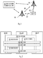
- Figure 1 depicts an example of a simplified system architecture only showing some elements and functional entities, all being logical units, whose implementation may differ from what is shown.
- the example of Figure 1 shows a part of a radio access network represented by access nodes 104, 106.
- a terminal device 100 may be configured to be in a wireless connection on one or more communication channels in a cell with an access node, such as (e/g)NodeB 104, 106 providing the cell.
- a physical link 105, 107 from the terminal device to the access node 104, 106 is called an uplink or a reverse link and a physical link from the access node to the terminal device is called a downlink or a forward link.
- access nodes 104, 106 or their functionalities may be implemented by using any node, host, server or access point etc. entity suitable for such a usage.
- the term (e/g)NodeB used above may refer to eNodeB (i.e. eNB) and/or gNodeB (i.e. gNB), for example.
- a communication system typically comprises more than one access node in which case the access nodes may also be configured to communicate with one another over links 109, wired or wireless, designed for the purpose.
- An example of such a link is Xn interface in the 5G system. These links may be used for signaling purposes.
- the access node may be a computing device configured to control the radio resources of the cellular communication system it is coupled to.
- Access node such as the access node 104 or 106, may also be called a base station, an access point, a network node, network element or any other type of interfacing device.
- the access node includes or is coupled to transceivers. From the transceivers of the access node, a connection is provided to one or more antenna units that establish bi-directional radio links to user devices.
- the antenna unit may comprise a plurality of antennas or antenna elements.
- the access node 104 is further connected to a core network 110 (CN or next generation core NGC).
- the core network typically comprises core network elements such as a serving gateway (S-GW, routing and forwarding user data packets), packet data network gateway (P-GW), for providing connectivity of terminal devices (UEs) to external packet data networks, or mobile management entity (MME), etc.
- S-GW serving gateway
- P-GW packet data network gateway
- MME mobile management entity
- the 5G specifications define a user plane function (UPF) as one of the core network elements 110 that handle user plane packet forwarding.
- UPF user plane function
- the terminal device 100 (also called UE, user equipment, user terminal, etc.) illustrates one type of an apparatus to which resources on the air interface are allocated and assigned.
- the user device typically refers to a portable computing device that includes wireless mobile communication devices operating with or without a subscriber identification module (SIM), including, but not limited to, the following types of devices: a mobile station (mobile phone), smartphone, personal digital assistant (PDA), handset, device using a wireless modem (alarm or measurement device, etc.), laptop and/or touch screen computer, tablet, game console, notebook, multimedia device, Machine Type Communication (MTC) device, and/or vehicular user device.
- SIM subscriber identification module
- a user device may also be a nearly exclusive uplink only device, of which an example is a camera or video camera loading images or video clips to a network.
- a user device may also be a device having capability to operate in Internet of Things (loT) network which is a scenario in which objects are provided with the ability to transfer data over a network without requiring human-to-human or human-to-computer interaction.
- the user device (or in some embodiments a layer 3 relay node) is configured to perform one or more of user equipment functionalities.
- the user device may also be called a subscriber unit, mobile station, remote terminal, access terminal, user terminal or user equipment (UE) just to mention but a few names or apparatuses.
- the current architecture in LTE networks is fully distributed in the radio and fully centralized in the core network.
- the low latency applications and services in 5G require to bring the content close to the radio which leads to local break out and multi-access edge computing (MEC).
- MEC multi-access edge computing
- 5G enables analytics and knowledge generation to occur at the source of the data. This approach requires leveraging resources that may not be continuously connected to a network such as laptops, smartphones, tablets and sensors.
- MEC provides a distributed computing environment for application and service hosting. It also has the ability to store and process content in close proximity to cellular subscribers for faster response time.
- Edge computing covers a wide range of technologies such as wireless sensor networks, mobile data acquisition, mobile signature analysis, cooperative distributed peer-to-peer ad hoc networking and processing also classifiable as local cloud/fog computing and grid/mesh computing, dew computing, mobile edge computing, cloudlet, distributed data storage and retrieval, autonomic self-healing networks, remote cloud services, augmented and virtual reality, data caching, Internet of Things (massive connectivity and/or latency critical), critical communications (autonomous vehicles, traffic safety, real-time analytics, time-critical control, healthcare applications).
- the cellular communication system is also able to communicate with other networks, such as a public switched telephone network or the Internet, or utilize services provided by them.
- the cellular communication network may also be able to support the usage of cloud services, for example at least part of core network operations may be carried out as a cloud service.
- Edge cloud may be brought into radio access network (RAN) by utilizing network function virtualization (NVF) and software defined networking (SDN).
- RAN radio access network
- NVF network function virtualization
- SDN software defined networking
- Using edge cloud may mean access node operations to be carried out, at least partly, in a server, host or node operationally coupled to a remote radio head or base station comprising radio parts. It is also possible that node operations will be distributed among a plurality of servers, nodes or hosts.
- Application of cloudRAN architecture enables RAN real time functions being carried out at the RAN side (in a distributed unit) and non-real time functions being carried out in a centralized manner in a centralized unit (CU).
- the CU may be comprised in the core network or in the cloud but, in some embodiments, the CU is comprised in one or more of the access nodes.
- the depicted system is only an example of a part of a radio access system and in practice, the system may comprise a plurality of access nodes, such as (e/gNodeBs), the terminal device may have an access to a plurality of radio cells and the system may comprise also other apparatuses, such as physical layer relay nodes or other network elements, etc.
- the terminal device employs multi-connectivity where multiple access nodes 104, 106 are configured to provide the terminal device 100 with radio access simultaneously.
- one of the access nodes 104, 106 may be a master access node managing the connections.
- the master access node may communicate with the terminal device over a primary component carrier.
- a secondary access node 104, 106 may provide the radio access under the control of the master access node 104, 106 via one or more secondary component carriers.
- Radio cells may comprise macro cells (or umbrella cells) which are large cells, usually having a diameter of up to tens of kilometers, and smaller cells such as micro-, femto- or picocells.
- the access nodes of Figure 1 may provide any kind of these cells.
- a cellular radio system may be implemented as a multilayer network including several kinds of cells. Typically, in multilayer networks, one access node provides one kind of a cell or cells, and thus a plurality of access nodes are required to provide such a network structure.
- FIG. 2 illustrates data routing between the core network and the terminal device.
- the core network element establishing a protocol data unit (PDU) session with the terminal device 100 is the UPF in the 5G system.
- the core network may establish one or more PDU sessions.
- one or more quality-of-service (QoS) flows 220, 222, 224 may be established.
- QoS flow may have unique requirements in terms of data throughput, latency, etc.
- one QoS flow may be allocated to a voice service while another QoS flow may be allocated to a web browser or e-mail service.
- the access node 104 may map the QoS flows to radio bearers 210, 211 flexibly.
- multiple QoS flows 220, 222 may be allocated to the same radio bearer 210.
- One or more radio bearers 210, 211 may be established from the same access node to the terminal device.
- the terminal device may have established simultaneous radio bearers with multiple access nodes 104, 106.
- each access node 104, 106 may forward data packets directly between the UPF and the terminal device.
- the secondary access node may forward a data packet received from the terminal device directly to the UPF and not through the master access node.
- An interface between the access node 104 and the UPF is called next generation user plane interface (NG-U).
- NG-U next generation user plane interface
- a task of the master access node may be to determine a hosting access node (a host) for each QoS flow.
- the host for a given QoS flow may be any one of the access nodes serving the terminal device, or even a new access node may be assigned to serve the terminal device.
- One of the radio bearers of the terminal device 100 may be defined as a default radio bearer.
- the default radio bearer may be a data radio bearer.
- the new QoS flow may remain unnoticed by the master access node.
- the master access node may not be able to assign a new host for the new QoS flow and the new QoS flow may remain mapped to the default radio bearer that is possibly not suitable for the QoS flow. For example, if the new QoS flow requires low latency and the default radio bearer is for e-mail or another delay-tolerant data, quality of experience may degrade.
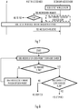
- Figures 3 to 5 illustrate some embodiments for establishing a host for a QoS flow.
- Figure 3 illustrates a process carried out by the secondary access node
- Figure 4 illustrates a process carried out by the terminal device
- Figure 5 illustrates a process carried out by the master access node.
- the process executed in the secondary access node comprises: detecting (YES in block 302), from an uplink data packet received (block 300) from the terminal device over a data radio bearer, a new QoS, flow in the data radio bearer; and upon said detecting in block 302, generating and transmitting (block 306) to a master access node of the connection a message indicating said detection of the new QoS flow, the message comprising an identifier of the new QoS flow.
- the process upon detecting in block 302 that the received uplink data packet belongs to a QoS flow readily configured and assigned to a radio bearer in the secondary access node, the process proceeds to block 304 where payload of the data packet is forwarded towards the core network, e.g. to the UPF 110.
- the secondary access node may perform block 304 and forward the payload of the new QoS flow towards the core network.
- the new QoS flow may still be associated with the default radio bearer and no QoS-flow-specific configurations have been made, e.g. to meet QoS requirements of the QoS flow.
- Data over the new QoS flow may be forwarded by the secondary access node.
- the UPF or another core network element receiving the forwarded payload is capable of detecting that the forwarded payload belongs to the new QoS flow and is capable of forming the necessary configurations for the new QoS flow on the core network side.
- the uplink data packet is a protocol data unit (PDU), such as a service data adaptation protocol PDU.
- PDU protocol data unit
- the secondary access node detects the new QoS flow by analysing a SDAP PDU received from the terminal device. If a QoS flow indicator comprised in a header of the SDAP message is new to the secondary access node, the detection of the new QoS flow may be triggered.
- the process executed in the terminal device comprises: detecting (block 400) a new QoS flow in the terminal device; determining (block 402) whether a default radio bearer of the terminal device is hosted by a secondary access node or a master access node of a connection between the terminal device and the cellular communication system; if the default radio bearer is determined to be hosted by the secondary access node (SECONDARY in block 402), generating and transmitting to the master access node a message indicating said establishment of the new QoS flow (block 406), the message comprising an identifier of the new QoS flow.
- the process may proceed to block 404 where an uplink data packet of the new QoS flow is generated and transmitted to the master access node over the default radio bearer hosted by the master access node.
- the uplink data packet serves as the message indicating the new QoS flow and the transmission of a separate indication message may be omitted.
- the process proceeds from block 406 to block 404.
- the generated uplink data packet is transmitted to the secondary access node over the default radio bearer hosted by the secondary access node.
- the detection of the new QoS flow may be triggered in block 400 further when the new QoS flow has no preconfigured mapping with one or more data radio bearers and, as a consequence, is mapped with the default radio bearer. It may be understood to mean that the terminal device has not yet received any radio bearer assignment from any access node.
- the process executed in the master access node comprises: an optional step of configuring a secondary access node of the connection to host a default radio bearer of the terminal device (block 500); receiving (block 502) from the secondary access node configured to host the default radio bearer or the terminal device a message indicating establishment of a new QoS flow for the terminal device, the message comprising an identifier of the new QoS flow; and upon receiving the message, determining (block 504) a host for the new QoS flow amongst the master access node and the secondary access node; and performing, upon determining that the master access node shall host the new QoS flow (MASTER in block 504), relocation of the new QoS flow from the secondary access node to the master access node (block 506).
- the process may end.
- An initial condition in block 500 may be that at least one QoS flow of the terminal device is mapped to a data radio bearer hosted by the master access node in block 500 and at least one other QoS flow of the terminal device is mapped to a data radio bearer hosted by the secondary access node.
- Another possible scenario is that only the secondary access node hosts a data radio bearer for the terminal device, the default radio bearer.
- the master access node hosts one data radio bearer while the secondary access node hosts only the default radio bearer.
- Figures 6 to 8 illustrate some embodiments of the processes of Figures 3 and 5 where the secondary access node indicates the establishment of the new QoS flow
- Figure 9 illustrates an embodiment of the processes of Figures 4 and 5 where the terminal device indicates the establishment of the new QoS flow.
- a system comprising the master access node, the secondary access node, and the terminal device operates such that only one of the secondary access node and the terminal device reports the establishment of the new QoS flow.
- the system may operate alternatively in such a manner that both the terminal device and the secondary access node are provided with the capability of reporting the establishment of the new QoS flow to the master node.
- the secondary access node may detect the new QoS flow in an uplink data packet received over the default radio bearer from the terminal device (UE) in block 600.
- Block 600 may comprise block 302 described above.
- the secondary access node may generate the message.
- the message is a QoS flow notification message comprising the identifier of the new QoS flow.
- the notification message may be a message to which the secondary access node waits for no response from the master access node.
- the secondary access node transmits the QoS flow notification message to the master access node over the signalling link between the access nodes, e.g. the Xn interface.
- the message further comprises an identifier of the terminal device and/or an identifier of a protocol data unit (PDU) session of the new QoS flow.
- PDU protocol data unit
- the master access node may acquire the identifier of the terminal device and/or the identifier of the PDU session in another manner than from the message indicating the establishment of the new QoS flow, e.g. in a separate message from the secondary access node or from the terminal device.
- the QoS flow notification message is comprised in Activity Notification Xn-message defines in the 3GPP specifications.
- the Activity Notification message is used to send a notification for one or several QoS flows or PDU sessions between access nodes.
- the conventional Activity Notification message may be modified to comprise at least one information element indicating the establishment of the new QoS flow in the default radio bearer.
- the Activity Notification message may use an existing field or a new field may be generated for conveying the identifier of the new QoS flow.
- the identifier may be a QoS flow identifier QFI defined in the 3GPP specifications.
- the Activity Notification message may include new cause value such as "New QoS flow".
- Block 606 comprises a QoS flow relocation procedure in which the terminal device and the access node selected as the host for the new QoS flow are configured to establish the required radio bearer(s) for the new QoS flow.
- Block 606 may comprise performing a radio resource control (RRC) reconfiguration for the terminal device.
- the RRC configuration may comprise mapping the new QoS flow to one or more radio bearers.
- One or more new radio bearers may be established for the new QoS flow, and/or the new QoS flow may be allocated to existing one or more radio bearers.
- the secondary access node may make an autonomous decision of whether or not to execute block 608 where the secondary access node maps the new QoS flow to one or more radio bearers hosted by the secondary access node.
- the secondary access node decides to execute block 608.
- the secondary access node starts a timer when executing step 602 and, upon expiry of the timer, executes block 608.
- the timer may be configured to count a time interval that enables execution of block 606 by the master access node such that the secondary access node does not perform block 608 unnecessarily. This procedure may be advantageous when the secondary access node has no capacity for the new QoS flow, for instance.
- the secondary access node may forward uplink packets of the new QoS flow towards the core network (block 604).
- the secondary access node buffers the uplink packets until the necessary configurations for the new QoS flow have been completed.
- the message is a reconfiguration request requesting the master access node to reconfigure at least one radio bearer for the new QoS flow.
- Figure 7 illustrates a process according to this embodiment. The same reference numbers in different Figures refer to the same or substantially similar functions.
- the secondary access node may generate and transmit the message as a modification request message in step 700.
- the modification response mandates a response from the master access node.
- the master access node may execute block 504.
- the master access node may execute block 606.
- block 606 comprises generating and transmitting a modification response message from the master access node to the secondary access node as a response to the modification request of block 700.
- the modification response message indicates to the secondary access node that the master access node has accepted the request and is relocating the new QoS flow from the secondary access node to another access node.
- the secondary access node may then release the new QoS flow from a context of the terminal device.
- the process may proceed to step 702 where the master access node generates and transmits a modification rejected message responding to the modification request of 700.
- the modification request is a Secondary Node Modification Required message of 3GPP specifications.
- the message may be arranged to include an information element comprising the QFI or another identifier of the new QoS flow and, optionally, other identifiers such as the terminal device identifier and/or the PDU session identifier.
- the message may be arranged to include a case value "New QoS Flow" indicating to the master access node that step 700 was triggered by the detection of the new QoS flow.
- the identifier such as QFI may be for example included in a new information element or the QFI may be included into CG ConfigInfo message of the PDU session Resources to be released item.
- block 606 comprises a master node (MN) initiated secondary node (SN) modification procedure specified in the 3GPP specifications.
- the procedure comprises the master node transmitting a SN modification request (SgNB modification request in the 3GPP specifications) to the secondary node to request the secondary node to release the new QoS flow.
- SgNB modification request in the 3GPP specifications
- master node may transmit a SN modification request to the other secondary node to request the other secondary node to host the new QoS flow.
- the SN modification request may comprise an identifier of the new QoS flow.
- the secondary node(s) may confirm or reject the request by responding with a SN modification confirm message or SN modification refuse message, respectively.
- the secondary node may carry out a radio resource connection (RRC) reconfiguration procedure to reconfigure one or more radio bearers for the new QoS flow.
- RRC radio resource connection
- the RRC reconfiguration may reconfigure a RRC connection between the secondary node and the terminal device.
- the secondary access node supports only one of the embodiments of Figures 6 and 7 .
- the secondary access node supports both embodiments of Figures 6 and 7 and comprises a logic for selecting the manner in which the new QoS flow is indicated to the master access node.
- Figure 8 illustrates an embodiment of the selection logic of the secondary access node.
- the secondary access node may then determine, in block 800, capability of the secondary access node to serve the new QoS flow.
- Block 800 may comprise considering a traffic load and capacity at the secondary access node, quality of a radio channel between the secondary access node and the terminal device, and/or other factor affecting the capability.
- the secondary access node may select the embodiment of Figure 6 and execute step 602 by transmitting the QoS flow notification message. In this case, the secondary access node may deem that no modifications by the master access node are needed to accommodate the new QoS flow. If the master access node still determines to perform the QoS flow relocation in block 606, it may do so.
- the secondary access node may select the embodiment of Figure 7 and execute step 700 in which the secondary access node requests the master access node to perform the relocation.
- the terminal device reports the new QoS flow to the master access node with reference to Figure 9 .
- the terminal device upon detecting the new QoS flow in the terminal device (block 900) and that the default radio bearer is hosted by the secondary access node, the terminal device generates and transmits the message indicating the new QoS flow to the master access node (step 902).
- the new QoS flow may be detected upon receiving an identifier of the new QoS flow from the UPF 110 over the default radio bearer, for example.
- the master access node may execute block 504.
- the process may proceed to step 904 where the terminal device transmits a data packet of the new QoS flow to the secondary access node over the default radio bearer.
- the secondary access node detects the new QoS flow (block 600) and maps the new QoS flow to one or more data radio bearers.
- the master access node may perform the QoS flow relocation in block 606 in the above-described manner.
- the terminal device selects a data radio bearer for the message on the basis of priorities of the data radio bearers the terminal device has with the master access node.
- the terminal device may select the data radio bearer having the highest priority and transmit the message on the selected data radio bearer.
- the message is a user plane message.
- the message is a service data adaptation protocol (SDAP) message.
- SDAP service data adaptation protocol
- the message may be a SDAP control message.
- the message has the same format as an end-marker control PDU.
- the end-marker PDU is conventionally used in connection with relocating a QoS flow from a first data radio bearer to a second data radio bearer, and the end-marker PDU is transmitted as the last PDU of the QoS flow in the first data radio bearer, thereby serving as an end-mark of the QoS flow in the first data radio bearer.
- Table 1 below illustrates a structure of the end-marker PDU.
- the end-marker PDU may have the length of one octet. It may comprise a field or a bit for indicating whether the end-marker PDU is a data PDU or a control PDU. It may also comprise the identifier of the QoS flow, e.g. the QFI. Remaining bit may be reserved. When the end-marker PDU is transmitted in step 902, the data/control bit may be set to indicate a control PDU.
- the master access node may check the QFI comprised in the end-marker PDU. If the QFI is for a QoS flow new to the master access node, e.g. as a QoS flow having no allocated data radio bearers, the master access node may determine that the message indicates establishment of the new QoS flow.
- Figure 10 illustrates an embodiment of a structure of the above-mentioned functionalities of an apparatus executing the functions of the access node in the process of Figure 3 (secondary access node) or Figure 5 (master access node) or any one of the embodiment described above for the access nodes.
- the apparatus may be the master access node or the secondary access node.
- the apparatus carrying out the above-described functionalities of the access node is comprised in such a device, e.g. the apparatus may comprise a circuitry, e.g. a chip, a chipset, a processor, a micro controller, or a combination of such circuitries in the access node.
- the apparatus may be an electronic device comprising electronic circuitries for realizing some embodiments of the access node.
- the apparatus may comprise a first communication interface 22 or a communication circuitry configured to provide the apparatus with capability for bidirectional communication with terminal devices 100 over a radio interface.
- the communication interface may comprise at least one radio modem and radio frequency circuitries for processing received control frames and data frames and control frames and data frames to be transmitted.
- the communication interface 22 may comprise standard well-known components such as the radio modem, an amplifier, a filter, a frequency converter, and encoder/decoder circuitries.
- the apparatus may further comprise a second communication interface 30 or a communication circuitry configured to provide the apparatus with capability for bidirectional communication with other access nodes and the core network elements, as described above.
- the communication interface 30 may comprise circuitries for processing messages described above in connection with steps 306, 502, 602, and 700, for example.
- the communication interface 22 may comprise standard well-known components such as a modem, an amplifier, a filter, and encoder/decoder circuitries.
- the apparatus may further comprise a memory 20 storing one or more computer program products 24 configuring the operation of at least one processor 10 of the apparatus.
- the memory 20 may further store a configuration database 26 storing operational configurations of the apparatus, e.g. the mappings between the QoS flows and the radio access bearers hosted by the access node.
- the configuration database may further store information on the QoS flows hosted by secondary access nodes controlled by the master access node.
- the apparatus may further comprise the at least one processor 10 configured to carry out the process of Figure 3 or any one of its embodiments, or the process of Figure 5 or any one of its embodiments.
- the processor(s) 10 comprise(s) a QoS flow controller 14 configured to manage the QoS flows in the access node, perform mappings between the QoS flows and the data radio bearers, etc.
- the QoS flow controller may perform necessary (re)configurations to meet QoS requirements of the QoS flows hosted by the access node.
- the QoS flow controller 14 may allocate more data radio bearers to the QoS flow or transfer the QoS flow from one data radio bearer to another.
- a radio access controller 16 may establish, manage, and release data radio bearers under the control of the QoS flow controller.
- a PDU processor 18 may manage transfer (transmission and reception) of data packets over the data radio bearers established by the radio access controller 16. The PDU processor may forward the data between the UPF and the terminal device, as described above.
- the PDU processor 18 may read a QoS flow identifier of the received data packet. If the QoS flow identifier is new to the PDU processor, the PDU processor may notify the QoS flow controller of the new QoS flow. If the apparatus is for the secondary access node, the QoS flow controller may then trigger the execution of block 306, 602, or 700, depending on the embodiment.
- the QoS flow controller may receive the message indicating a new QoS flow through one of the interfaces 22, 30, depending on the embodiment. Upon detecting the new QoS flow allocated to the default radio bearer hosted by a secondary access node, the QoS flow controller may execute block 504.
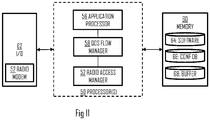
- Figure 11 illustrates an embodiment of a structure of the above-mentioned functionalities of an apparatus executing the process of Figure 4 or any one of the above-described embodiments performed by the terminal device.
- the apparatus may be the terminal device. In other embodiments, the apparatus may be a circuitry or an electronic device realizing some embodiments of the invention in the terminal device.
- the apparatus may comply with 3GPP specifications for the next generation radio access network (NG-RAN) also called a 5G system.
- the apparatus may be or may be comprised in a computer (PC), a laptop, a tablet computer, a cellular phone, a palm computer, a sensor device, or any other apparatus provided with radio communication capability.
- PC computer
- the apparatus carrying out the above-described functionalities is comprised in such a device, e.g. the apparatus may comprise a circuitry such as a chip, a chipset, a processor, a micro controller, or a combination of such circuitries in any one of the above-described devices.
- the apparatus may be an electronic device comprising electronic circuitries for realizing some embodiments of the present invention.
- the apparatus may comprise a radio interface 62 providing the apparatus with radio communication capability within a wireless network provided by one or more access nodes.
- the radio interface may comprise a radio modem 52 and a radio frequency (RF) front end comprising standard well-known components such as an amplifier, filter, frequency-converter, (de)modulator, and encoder/decoder circuitries and one or more antennas.
- RF radio frequency
- the apparatus may further comprise a memory 60 storing one or more computer program products 62 configuring the operation of at least one processor of the apparatus.
- the memory 60 may further store a configuration database 64 storing operational configurations of the apparatus.
- the configuration database 64 may, for example, store the mappings between QoS flows of the apparatus and respective data radio bearers.
- the apparatus may further comprise the at least one processor 50 managing the operation of the apparatus.
- the at least one processor 50 may comprise an application processor 56 forming an application layer.
- the application processor may execute computer programs forming the primary function of the apparatus. For example, if the apparatus is a sensor device, the application processor may execute one or more signal processing applications processing measurement data acquired from one or more sensor heads. If the apparatus is a computer system of a vehicle, the application processor may execute a media application and/or an autonomous driving and navigation application.
- the application processor may generate data to be transmitted over the radio interface and receive data through the radio interface.
- the application processor may output data transfer requests to a QoS flow manager 58.
- the QoS flow manager 58 may manage QoS flows in the apparatus.
- the QoS flow manager may determine QoS flow requirements for the data transfer. Then, the QoS flow manager may establish a new QoS flow for the application data. Upon establishing a new QoS flow, the QoS flow manager may execute the process of Figure 4 .
- the QoS flow manager may control a radio access manager 52 to determine the host of the default radio bearer and, upon detecting that the default radio bearer is a secondary access node, cause execution of block 406.
- the radio access manager 52 may manage the radio bearers and transfer of messages with one or more access nodes over the radio bearers.
- circuitry refers to one or more of the following: (a) hardware-only circuit implementations such as implementations in only analog and/or digital circuitry; (b) combinations of circuits and software and/or firmware, such as (as applicable): (i) a combination of processor(s) or processor cores; or (ii) portions of processor(s)/software including digital signal processor(s), software, and at least one memory that work together to cause an apparatus to perform specific functions; and (c) circuits, such as a microprocessor(s) or a portion of a microprocessor(s), that require software or firmware for operation, even if the software or firmware is not physically present.
- circuitry would also cover an implementation of merely a processor (or multiple processors) or portion of a processor, e.g. one core of a multi-core processor, and its (or their) accompanying software and/or firmware.
- circuitry would also cover, for example and if applicable to the particular element, a baseband integrated circuit, an application-specific integrated circuit (ASIC), and/or a field-programmable grid array (FPGA) circuit for the apparatus according to an embodiment of the invention.
- ASIC application-specific integrated circuit
- FPGA field-programmable grid array
- the processes or methods described in Figures 3 to 9 may also be carried out in the form of one or more computer processes defined by one or more computer programs.
- a separate computer program may be provided in one or more apparatuses that execute functions of the processes described in connection with the Figures.
- the computer program(s) may be in source code form, object code form, or in some intermediate form, and it may be stored in some sort of carrier, which may be any entity or device capable of carrying the program.
- Such carriers include transitory and/or non-transitory computer media, e.g. a record medium, computer memory, read-only memory, electrical carrier signal, telecommunications signal, and software distribution package.
- the computer program may be executed in a single electronic digital processing unit or it may be distributed amongst a number of processing units.
- Embodiments described herein are applicable to wireless networks defined above but also to other wireless networks.
- the protocols used, the specifications of the wireless networks and their network elements develop rapidly. Such development may require extra changes to the described embodiments. Therefore, all words and expressions should be interpreted broadly and they are intended to illustrate, not to restrict, the embodiment. It will be obvious to a person skilled in the art that, as technology advances, the inventive concept can be implemented in various ways. Embodiments are not limited to the examples described above but may vary within the scope of the claims.
Landscapes
- Engineering & Computer Science (AREA)
- Computer Networks & Wireless Communication (AREA)
- Signal Processing (AREA)
- Mobile Radio Communication Systems (AREA)
Claims (15)
- Appareil pour un nœud d'accès secondaire (104, 106) d'une connexion entre un dispositif terminal (100) et un système de communication cellulaire (110), caractérisé par des moyens pour réaliser les étapes suivantes :détecter, à partir d'un paquet de données de liaison montante reçu à partir du dispositif terminal sur un support radio de données, un nouveau flux de qualité de service, QoS, dans le support radio de données ;à ladite détection, générer et transmettre à un nœud d'accès maître de la connexion un message indiquant ladite détection du nouveau flux QoS, le message comprenant un identifiant du nouveau flux QoS.
- Appareil selon la revendication 1, dans lequel le message est un message de notification auquel l'appareil n'attend pas de réponse à partir du nœud d'accès maître.
- Appareil selon la revendication 1, dans lequel le message est une demande de reconfiguration demandant au nœud d'accès maître de reconfigurer au moins un support radio pour le nouveau flux QoS.
- Appareil pour un dispositif terminal (100) d'un système de communication cellulaire, caractérisé par des moyens pour réaliser les étapes suivantes :détecter un nouveau flux de qualité de service, QoS, dans le dispositif terminal ;déterminer si un support radio par défaut du dispositif terminal est hébergé par un nœud d'accès secondaire ou un nœud d'accès maître d'une connexion entre le dispositif terminal et le système de communication cellulaire ;si le support radio par défaut est déterminé comme étant hébergé par le nœud d'accès secondaire, générer et transmettre au nœud d'accès maître un message indiquant ledit établissement du nouveau flux QoS, le message comprenant un identifiant du nouveau flux QoS.
- Appareil selon la revendication 4, dans lequel les moyens sont en outre configurés, si le support radio par défaut est déterminé comme étant hébergé par le nœud d'accès maître, pour ne pas générer le message.
- Appareil selon la revendication 4 ou 5, dans lequel le message est un message de protocole d'adaptation de données de service.
- Appareil selon l'une quelconque des revendications précédentes 4 à 6, dans lequel le message a le même format qu'une unité de données de protocole de commande de marqueur de fin.
- Appareil selon l'une quelconque des revendications précédentes 4 à 7, dans lequel, au moment de ladite détection, le nouveau flux QoS n'a pas de mappage préconfiguré avec un ou plusieurs supports radio, et est donc mappé avec le support radio par défaut.
- Appareil pour un nœud d'accès maître (104, 106) d'une connexion entre un dispositif terminal (100) et un système de communication cellulaire (110), caractérisé par des moyens pour réaliser les étapes suivantes :recevoir, à partir du nœud d'accès secondaire configuré pour héberger un support radio par défaut du dispositif terminal ou à partir du dispositif terminal, un message indiquant l'établissement d'un nouveau flux de qualité de service, QoS, pour le dispositif terminal, le message comprenant un identifiant du nouveau flux QoS ; età la réception du message, déterminer un hôte pour le nouveau flux QoS parmi le nœud d'accès maître et le nœud d'accès secondaire ; etréaliser, lorsqu'il a été déterminé que le nœud d'accès maître doit héberger le nouveau flux QoS, une relocalisation du nouveau flux QoS du nœud d'accès secondaire au nœud d'accès maître.
- Appareil selon la revendication 9, dans lequel les moyens sont en outre configurés pour recevoir le message à partir du dispositif terminal comme message de plan d'utilisateur.
- Appareil selon la revendication 9, dans lequel les moyens sont en outre configurés pour recevoir le message à partir du nœud d'accès secondaire comme message de notification et, lorsqu'il a été déterminé que le nœud d'accès secondaire doit héberger le nouveau flux QoS, pour ne transmettre aucune réponse au message de notification au nœud d'accès secondaire.
- Appareil selon l'une quelconque des revendications précédentes 1 à 11, dans lequel le message comprend en outre un identifiant du dispositif terminal et/ou un identifiant d'une session d'unité de données de protocole du nouveau flux QoS.
- Procédé pour un nœud d'accès secondaire (104, 106) d'une connexion entre un dispositif terminal (100) et un système de communication cellulaire (110), caractérisé par :la détection (302), par le nœud d'accès secondaire à partir d'un paquet de données de liaison montante reçu à partir du dispositif terminal sur un support radio de données, d'un nouveau flux de qualité de service, QoS, dans le support radio de données ;à ladite détection, la génération et la transmission (306) à un nœud d'accès maître de la connexion d'un message indiquant ladite détection du nouveau flux QoS, le message comprenant un identifiant du nouveau flux QoS.
- Procédé pour un dispositif terminal (100) d'un système de communication cellulaire (110), caractérisé par :la détection (400) d'un nouveau flux de qualité de service, QoS, dans le dispositif terminal ;la détermination (402) précisant si un support radio par défaut du dispositif terminal est hébergé par un nœud d'accès secondaire ou un nœud d'accès maître d'une connexion entre le dispositif terminal et le système de communication cellulaire ;si le support radio par défaut est déterminé comme étant hébergé par le nœud d'accès secondaire, la génération et la transmission (406) au nœud d'accès maître d'un message indiquant ledit établissement du nouveau flux QoS, le message comprenant un identifiant du nouveau flux QoS.
- Procédé pour un nœud d'accès maître (104, 106) d'une connexion entre un dispositif terminal (100) et un système de communication cellulaire (110), caractérisé par :la réception (502), à partir du nœud d'accès secondaire configuré pour héberger un support radio par défaut du dispositif terminal ou à partir du dispositif terminal, d'un message indiquant l'établissement d'un nouveau flux de qualité de service, QoS, pour le dispositif terminal, le message comprenant un identifiant du nouveau flux QoS ; età la réception du message, la détermination (504) d'un hôte pour le nouveau flux QoS parmi le nœud d'accès maître et le nœud d'accès secondaire ; etla réalisation (506), lorsqu'il a été déterminé que le nœud d'accès maître doit héberger le nouveau flux QoS, d'une relocalisation du nouveau flux QoS du nœud d'accès secondaire au nœud d'accès maître.
Priority Applications (2)
| Application Number | Priority Date | Filing Date | Title |
|---|---|---|---|
| EP18203354.8A EP3648540B1 (fr) | 2018-10-30 | 2018-10-30 | Mappage de flux de qualité de service à des porteuses radio |
| CN201911039037.4A CN111132226B (zh) | 2018-10-30 | 2019-10-29 | 将服务质量流映射到无线电承载 |
Applications Claiming Priority (1)
| Application Number | Priority Date | Filing Date | Title |
|---|---|---|---|
| EP18203354.8A EP3648540B1 (fr) | 2018-10-30 | 2018-10-30 | Mappage de flux de qualité de service à des porteuses radio |
Publications (2)
| Publication Number | Publication Date |
|---|---|
| EP3648540A1 EP3648540A1 (fr) | 2020-05-06 |
| EP3648540B1 true EP3648540B1 (fr) | 2022-01-05 |
Family
ID=64083011
Family Applications (1)
| Application Number | Title | Priority Date | Filing Date |
|---|---|---|---|
| EP18203354.8A Active EP3648540B1 (fr) | 2018-10-30 | 2018-10-30 | Mappage de flux de qualité de service à des porteuses radio |
Country Status (2)
| Country | Link |
|---|---|
| EP (1) | EP3648540B1 (fr) |
| CN (1) | CN111132226B (fr) |
Family Cites Families (5)
| Publication number | Priority date | Publication date | Assignee | Title |
|---|---|---|---|---|
| US20060114855A1 (en) * | 2004-11-30 | 2006-06-01 | Haihong Zheng | Quality of service (QOS) signaling for a wireless network |
| US9596707B2 (en) * | 2014-03-13 | 2017-03-14 | Intel Corporation | Bearer mobility and splitting in a radio access network-based, 3rd generation partnership project network having an integrated wireless local area network |
| US11265884B2 (en) * | 2016-09-30 | 2022-03-01 | Apple Inc. | Systems, methods and devices for uplink bearer and access category mapping |
| EP3536095A1 (fr) * | 2016-11-04 | 2019-09-11 | Telefonaktiebolaget LM Ericsson (publ) | Mise en correspondance réfléchissante de flux avec des supports radio |
| EP3567919B1 (fr) * | 2017-01-05 | 2022-04-27 | LG Electronics Inc. | Procédé et dispositif de transmission de règle pour un mappage de flux qos sur drb |
-
2018
- 2018-10-30 EP EP18203354.8A patent/EP3648540B1/fr active Active
-
2019
- 2019-10-29 CN CN201911039037.4A patent/CN111132226B/zh active Active
Also Published As
| Publication number | Publication date |
|---|---|
| CN111132226B (zh) | 2023-01-31 |
| CN111132226A (zh) | 2020-05-08 |
| EP3648540A1 (fr) | 2020-05-06 |
Similar Documents
| Publication | Publication Date | Title |
|---|---|---|
| US11716122B2 (en) | Beam management enhancement for FR2 with V-Pol/H-Pol virtualization | |
| US10966139B2 (en) | Apparatus and method for routing data packet to user equipment in LTE-WLAN aggregation system | |
| CN108713327B (zh) | 用于实现通信网络中的通信的网络节点和在网络节点中执行的方法 | |
| KR101868070B1 (ko) | 서비스 계층 사우스바운드 인터페이스 및 서비스 품질 | |
| KR102091476B1 (ko) | 통신 네트워크에서의 리소스 관리를 위한 리소스 컨트롤러 | |
| US10506644B2 (en) | Radio access network device, data processing method, and IP packet processing method | |
| US10461900B2 (en) | Hierarchical arrangement and multiplexing of mobile network resource slices for logical networks | |
| US11758000B2 (en) | System and method for survival time delivery in 5GC | |
| CN109819477B (zh) | 一种处理请求的方法以及相应实体 | |
| JP6855838B2 (ja) | 端末装置、方法及びプログラム | |
| CN108366355A (zh) | 数据发送方法、数据发送终端以及基站 | |
| US12160286B2 (en) | Wireless communication systems and methods using virtualization across a horizontal and/or vertical polarization | |
| CN111757391A (zh) | 一种通信方法及装置 | |
| US11991663B2 (en) | Paging priority and wireless access for non-high priority access users during wireless network congestion | |
| CN114342511B (zh) | 通信方法和通信装置 | |
| EP3648540B1 (fr) | Mappage de flux de qualité de service à des porteuses radio | |
| KR20150039510A (ko) | 중요 데이터 패킷을 우선 처리하는 방법 및 장치 | |
| US10924983B2 (en) | Methods and apparatus for discovery signal transmission between a plurality of devices | |
| US20250024312A1 (en) | Enhanced quality of service support for mobile wireless networks | |
| US10361974B1 (en) | Controlling base station buffering of data for a wireless communication device based on the extent to which the wireless communication device provides connectivity for other devices | |
| CN119011513A (zh) | 一种通信方法及装置 |
Legal Events
| Date | Code | Title | Description |
|---|---|---|---|
| PUAI | Public reference made under article 153(3) epc to a published international application that has entered the european phase |
Free format text: ORIGINAL CODE: 0009012 |
|
| STAA | Information on the status of an ep patent application or granted ep patent |
Free format text: STATUS: THE APPLICATION HAS BEEN PUBLISHED |
|
| AK | Designated contracting states |
Kind code of ref document: A1 Designated state(s): AL AT BE BG CH CY CZ DE DK EE ES FI FR GB GR HR HU IE IS IT LI LT LU LV MC MK MT NL NO PL PT RO RS SE SI SK SM TR |
|
| AX | Request for extension of the european patent |
Extension state: BA ME |
|
| STAA | Information on the status of an ep patent application or granted ep patent |
Free format text: STATUS: REQUEST FOR EXAMINATION WAS MADE |
|
| 17P | Request for examination filed |
Effective date: 20201201 |
|
| RBV | Designated contracting states (corrected) |
Designated state(s): AL AT BE BG CH CY CZ DE DK EE ES FI FR GB GR HR HU IE IS IT LI LT LU LV MC MK MT NL NO PL PT RO RS SE SI SK SM TR |
|
| RIC1 | Information provided on ipc code assigned before grant |
Ipc: H04W 76/15 20180101AFI20210719BHEP Ipc: H04W 28/02 20090101ALI20210719BHEP Ipc: H04W 40/34 20090101ALI20210719BHEP |
|
| GRAP | Despatch of communication of intention to grant a patent |
Free format text: ORIGINAL CODE: EPIDOSNIGR1 |
|
| STAA | Information on the status of an ep patent application or granted ep patent |
Free format text: STATUS: GRANT OF PATENT IS INTENDED |
|
| INTG | Intention to grant announced |
Effective date: 20210910 |
|
| RIN1 | Information on inventor provided before grant (corrected) |
Inventor name: SEBIRE, BENOIST Inventor name: LAITILA, MATTI |
|
| GRAS | Grant fee paid |
Free format text: ORIGINAL CODE: EPIDOSNIGR3 |
|
| GRAA | (expected) grant |
Free format text: ORIGINAL CODE: 0009210 |
|
| STAA | Information on the status of an ep patent application or granted ep patent |
Free format text: STATUS: THE PATENT HAS BEEN GRANTED |
|
| AK | Designated contracting states |
Kind code of ref document: B1 Designated state(s): AL AT BE BG CH CY CZ DE DK EE ES FI FR GB GR HR HU IE IS IT LI LT LU LV MC MK MT NL NO PL PT RO RS SE SI SK SM TR |
|
| REG | Reference to a national code |
Ref country code: GB Ref legal event code: FG4D |
|
| REG | Reference to a national code |
Ref country code: CH Ref legal event code: EP |
|
| REG | Reference to a national code |
Ref country code: AT Ref legal event code: REF Ref document number: 1461739 Country of ref document: AT Kind code of ref document: T Effective date: 20220115 |
|
| REG | Reference to a national code |
Ref country code: DE Ref legal event code: R096 Ref document number: 602018029037 Country of ref document: DE |
|
| REG | Reference to a national code |
Ref country code: IE Ref legal event code: FG4D |
|
| REG | Reference to a national code |
Ref country code: LT Ref legal event code: MG9D |
|
| REG | Reference to a national code |
Ref country code: NL Ref legal event code: MP Effective date: 20220105 |
|
| REG | Reference to a national code |
Ref country code: AT Ref legal event code: MK05 Ref document number: 1461739 Country of ref document: AT Kind code of ref document: T Effective date: 20220105 |
|
| PG25 | Lapsed in a contracting state [announced via postgrant information from national office to epo] |
Ref country code: NL Free format text: LAPSE BECAUSE OF FAILURE TO SUBMIT A TRANSLATION OF THE DESCRIPTION OR TO PAY THE FEE WITHIN THE PRESCRIBED TIME-LIMIT Effective date: 20220105 |
|
| PG25 | Lapsed in a contracting state [announced via postgrant information from national office to epo] |
Ref country code: SE Free format text: LAPSE BECAUSE OF FAILURE TO SUBMIT A TRANSLATION OF THE DESCRIPTION OR TO PAY THE FEE WITHIN THE PRESCRIBED TIME-LIMIT Effective date: 20220105 Ref country code: RS Free format text: LAPSE BECAUSE OF FAILURE TO SUBMIT A TRANSLATION OF THE DESCRIPTION OR TO PAY THE FEE WITHIN THE PRESCRIBED TIME-LIMIT Effective date: 20220105 Ref country code: PT Free format text: LAPSE BECAUSE OF FAILURE TO SUBMIT A TRANSLATION OF THE DESCRIPTION OR TO PAY THE FEE WITHIN THE PRESCRIBED TIME-LIMIT Effective date: 20220505 Ref country code: NO Free format text: LAPSE BECAUSE OF FAILURE TO SUBMIT A TRANSLATION OF THE DESCRIPTION OR TO PAY THE FEE WITHIN THE PRESCRIBED TIME-LIMIT Effective date: 20220405 Ref country code: LT Free format text: LAPSE BECAUSE OF FAILURE TO SUBMIT A TRANSLATION OF THE DESCRIPTION OR TO PAY THE FEE WITHIN THE PRESCRIBED TIME-LIMIT Effective date: 20220105 Ref country code: HR Free format text: LAPSE BECAUSE OF FAILURE TO SUBMIT A TRANSLATION OF THE DESCRIPTION OR TO PAY THE FEE WITHIN THE PRESCRIBED TIME-LIMIT Effective date: 20220105 Ref country code: ES Free format text: LAPSE BECAUSE OF FAILURE TO SUBMIT A TRANSLATION OF THE DESCRIPTION OR TO PAY THE FEE WITHIN THE PRESCRIBED TIME-LIMIT Effective date: 20220105 Ref country code: BG Free format text: LAPSE BECAUSE OF FAILURE TO SUBMIT A TRANSLATION OF THE DESCRIPTION OR TO PAY THE FEE WITHIN THE PRESCRIBED TIME-LIMIT Effective date: 20220405 |
|
| PG25 | Lapsed in a contracting state [announced via postgrant information from national office to epo] |
Ref country code: PL Free format text: LAPSE BECAUSE OF FAILURE TO SUBMIT A TRANSLATION OF THE DESCRIPTION OR TO PAY THE FEE WITHIN THE PRESCRIBED TIME-LIMIT Effective date: 20220105 Ref country code: LV Free format text: LAPSE BECAUSE OF FAILURE TO SUBMIT A TRANSLATION OF THE DESCRIPTION OR TO PAY THE FEE WITHIN THE PRESCRIBED TIME-LIMIT Effective date: 20220105 Ref country code: GR Free format text: LAPSE BECAUSE OF FAILURE TO SUBMIT A TRANSLATION OF THE DESCRIPTION OR TO PAY THE FEE WITHIN THE PRESCRIBED TIME-LIMIT Effective date: 20220406 Ref country code: FI Free format text: LAPSE BECAUSE OF FAILURE TO SUBMIT A TRANSLATION OF THE DESCRIPTION OR TO PAY THE FEE WITHIN THE PRESCRIBED TIME-LIMIT Effective date: 20220105 Ref country code: AT Free format text: LAPSE BECAUSE OF FAILURE TO SUBMIT A TRANSLATION OF THE DESCRIPTION OR TO PAY THE FEE WITHIN THE PRESCRIBED TIME-LIMIT Effective date: 20220105 |
|
| PG25 | Lapsed in a contracting state [announced via postgrant information from national office to epo] |
Ref country code: IS Free format text: LAPSE BECAUSE OF FAILURE TO SUBMIT A TRANSLATION OF THE DESCRIPTION OR TO PAY THE FEE WITHIN THE PRESCRIBED TIME-LIMIT Effective date: 20220505 |
|
| REG | Reference to a national code |
Ref country code: DE Ref legal event code: R097 Ref document number: 602018029037 Country of ref document: DE |
|
| PG25 | Lapsed in a contracting state [announced via postgrant information from national office to epo] |
Ref country code: SM Free format text: LAPSE BECAUSE OF FAILURE TO SUBMIT A TRANSLATION OF THE DESCRIPTION OR TO PAY THE FEE WITHIN THE PRESCRIBED TIME-LIMIT Effective date: 20220105 Ref country code: SK Free format text: LAPSE BECAUSE OF FAILURE TO SUBMIT A TRANSLATION OF THE DESCRIPTION OR TO PAY THE FEE WITHIN THE PRESCRIBED TIME-LIMIT Effective date: 20220105 Ref country code: RO Free format text: LAPSE BECAUSE OF FAILURE TO SUBMIT A TRANSLATION OF THE DESCRIPTION OR TO PAY THE FEE WITHIN THE PRESCRIBED TIME-LIMIT Effective date: 20220105 Ref country code: EE Free format text: LAPSE BECAUSE OF FAILURE TO SUBMIT A TRANSLATION OF THE DESCRIPTION OR TO PAY THE FEE WITHIN THE PRESCRIBED TIME-LIMIT Effective date: 20220105 Ref country code: DK Free format text: LAPSE BECAUSE OF FAILURE TO SUBMIT A TRANSLATION OF THE DESCRIPTION OR TO PAY THE FEE WITHIN THE PRESCRIBED TIME-LIMIT Effective date: 20220105 Ref country code: CZ Free format text: LAPSE BECAUSE OF FAILURE TO SUBMIT A TRANSLATION OF THE DESCRIPTION OR TO PAY THE FEE WITHIN THE PRESCRIBED TIME-LIMIT Effective date: 20220105 |
|
| PLBE | No opposition filed within time limit |
Free format text: ORIGINAL CODE: 0009261 |
|
| STAA | Information on the status of an ep patent application or granted ep patent |
Free format text: STATUS: NO OPPOSITION FILED WITHIN TIME LIMIT |
|
| PG25 | Lapsed in a contracting state [announced via postgrant information from national office to epo] |
Ref country code: AL Free format text: LAPSE BECAUSE OF FAILURE TO SUBMIT A TRANSLATION OF THE DESCRIPTION OR TO PAY THE FEE WITHIN THE PRESCRIBED TIME-LIMIT Effective date: 20220105 |
|
| 26N | No opposition filed |
Effective date: 20221006 |
|
| PG25 | Lapsed in a contracting state [announced via postgrant information from national office to epo] |
Ref country code: SI Free format text: LAPSE BECAUSE OF FAILURE TO SUBMIT A TRANSLATION OF THE DESCRIPTION OR TO PAY THE FEE WITHIN THE PRESCRIBED TIME-LIMIT Effective date: 20220105 |
|
| PG25 | Lapsed in a contracting state [announced via postgrant information from national office to epo] |
Ref country code: MC Free format text: LAPSE BECAUSE OF FAILURE TO SUBMIT A TRANSLATION OF THE DESCRIPTION OR TO PAY THE FEE WITHIN THE PRESCRIBED TIME-LIMIT Effective date: 20220105 |
|
| REG | Reference to a national code |
Ref country code: CH Ref legal event code: PL |
|
| REG | Reference to a national code |
Ref country code: BE Ref legal event code: MM Effective date: 20221031 |
|
| GBPC | Gb: european patent ceased through non-payment of renewal fee |
Effective date: 20221030 |
|
| PG25 | Lapsed in a contracting state [announced via postgrant information from national office to epo] |
Ref country code: LU Free format text: LAPSE BECAUSE OF NON-PAYMENT OF DUE FEES Effective date: 20221030 |
|
| P01 | Opt-out of the competence of the unified patent court (upc) registered |
Effective date: 20230527 |
|
| PG25 | Lapsed in a contracting state [announced via postgrant information from national office to epo] |
Ref country code: LI Free format text: LAPSE BECAUSE OF NON-PAYMENT OF DUE FEES Effective date: 20221031 Ref country code: IT Free format text: LAPSE BECAUSE OF FAILURE TO SUBMIT A TRANSLATION OF THE DESCRIPTION OR TO PAY THE FEE WITHIN THE PRESCRIBED TIME-LIMIT Effective date: 20220105 Ref country code: FR Free format text: LAPSE BECAUSE OF NON-PAYMENT OF DUE FEES Effective date: 20221031 Ref country code: CH Free format text: LAPSE BECAUSE OF NON-PAYMENT OF DUE FEES Effective date: 20221031 |
|
| PG25 | Lapsed in a contracting state [announced via postgrant information from national office to epo] |
Ref country code: BE Free format text: LAPSE BECAUSE OF NON-PAYMENT OF DUE FEES Effective date: 20221031 |
|
| PG25 | Lapsed in a contracting state [announced via postgrant information from national office to epo] |
Ref country code: IE Free format text: LAPSE BECAUSE OF NON-PAYMENT OF DUE FEES Effective date: 20221030 Ref country code: GB Free format text: LAPSE BECAUSE OF NON-PAYMENT OF DUE FEES Effective date: 20221030 |
|
| PG25 | Lapsed in a contracting state [announced via postgrant information from national office to epo] |
Ref country code: HU Free format text: LAPSE BECAUSE OF FAILURE TO SUBMIT A TRANSLATION OF THE DESCRIPTION OR TO PAY THE FEE WITHIN THE PRESCRIBED TIME-LIMIT; INVALID AB INITIO Effective date: 20181030 |
|
| PG25 | Lapsed in a contracting state [announced via postgrant information from national office to epo] |
Ref country code: CY Free format text: LAPSE BECAUSE OF FAILURE TO SUBMIT A TRANSLATION OF THE DESCRIPTION OR TO PAY THE FEE WITHIN THE PRESCRIBED TIME-LIMIT Effective date: 20220105 |
|
| PG25 | Lapsed in a contracting state [announced via postgrant information from national office to epo] |
Ref country code: MK Free format text: LAPSE BECAUSE OF FAILURE TO SUBMIT A TRANSLATION OF THE DESCRIPTION OR TO PAY THE FEE WITHIN THE PRESCRIBED TIME-LIMIT Effective date: 20220105 |
|
| PG25 | Lapsed in a contracting state [announced via postgrant information from national office to epo] |
Ref country code: TR Free format text: LAPSE BECAUSE OF FAILURE TO SUBMIT A TRANSLATION OF THE DESCRIPTION OR TO PAY THE FEE WITHIN THE PRESCRIBED TIME-LIMIT Effective date: 20220105 |
|
| PG25 | Lapsed in a contracting state [announced via postgrant information from national office to epo] |
Ref country code: MT Free format text: LAPSE BECAUSE OF FAILURE TO SUBMIT A TRANSLATION OF THE DESCRIPTION OR TO PAY THE FEE WITHIN THE PRESCRIBED TIME-LIMIT Effective date: 20220105 |
|
| PGFP | Annual fee paid to national office [announced via postgrant information from national office to epo] |
Ref country code: DE Payment date: 20250902 Year of fee payment: 8 |