EP3649366B1 - Bremssattel mit abstützung und bremssatteldeformationsdetektionsverfahren - Google Patents
Bremssattel mit abstützung und bremssatteldeformationsdetektionsverfahren Download PDFInfo
- Publication number
- EP3649366B1 EP3649366B1 EP18749553.6A EP18749553A EP3649366B1 EP 3649366 B1 EP3649366 B1 EP 3649366B1 EP 18749553 A EP18749553 A EP 18749553A EP 3649366 B1 EP3649366 B1 EP 3649366B1
- Authority
- EP
- European Patent Office
- Prior art keywords
- caliper
- caliper body
- supporting element
- disc
- supporting
- Prior art date
- Legal status (The legal status is an assumption and is not a legal conclusion. Google has not performed a legal analysis and makes no representation as to the accuracy of the status listed.)
- Active
Links
Images


Classifications
-
- F—MECHANICAL ENGINEERING; LIGHTING; HEATING; WEAPONS; BLASTING
- F16—ENGINEERING ELEMENTS AND UNITS; GENERAL MEASURES FOR PRODUCING AND MAINTAINING EFFECTIVE FUNCTIONING OF MACHINES OR INSTALLATIONS; THERMAL INSULATION IN GENERAL
- F16D—COUPLINGS FOR TRANSMITTING ROTATION; CLUTCHES; BRAKES
- F16D65/00—Parts or details
- F16D65/005—Components of axially engaging brakes not otherwise provided for
- F16D65/0056—Brake supports
-
- F—MECHANICAL ENGINEERING; LIGHTING; HEATING; WEAPONS; BLASTING
- F16—ENGINEERING ELEMENTS AND UNITS; GENERAL MEASURES FOR PRODUCING AND MAINTAINING EFFECTIVE FUNCTIONING OF MACHINES OR INSTALLATIONS; THERMAL INSULATION IN GENERAL
- F16D—COUPLINGS FOR TRANSMITTING ROTATION; CLUTCHES; BRAKES
- F16D65/00—Parts or details
- F16D65/14—Actuating mechanisms for brakes; Means for initiating operation at a predetermined position
- F16D65/16—Actuating mechanisms for brakes; Means for initiating operation at a predetermined position arranged in or on the brake
- F16D65/18—Actuating mechanisms for brakes; Means for initiating operation at a predetermined position arranged in or on the brake adapted for drawing members together, e.g. for disc brakes
- F16D65/183—Actuating mechanisms for brakes; Means for initiating operation at a predetermined position arranged in or on the brake adapted for drawing members together, e.g. for disc brakes with force-transmitting members arranged side by side acting on a spot type force-applying member
-
- B—PERFORMING OPERATIONS; TRANSPORTING
- B60—VEHICLES IN GENERAL
- B60T—VEHICLE BRAKE CONTROL SYSTEMS OR PARTS THEREOF; BRAKE CONTROL SYSTEMS OR PARTS THEREOF, IN GENERAL; ARRANGEMENT OF BRAKING ELEMENTS ON VEHICLES IN GENERAL; PORTABLE DEVICES FOR PREVENTING UNWANTED MOVEMENT OF VEHICLES; VEHICLE MODIFICATIONS TO FACILITATE COOLING OF BRAKES
- B60T17/00—Component parts, details, or accessories of power brake systems not covered by groups B60T8/00, B60T13/00 or B60T15/00, or presenting other characteristic features
- B60T17/18—Safety devices; Monitoring
- B60T17/22—Devices for monitoring or checking brake systems; Signal devices
- B60T17/221—Procedure or apparatus for checking or keeping in a correct functioning condition of brake systems
-
- F—MECHANICAL ENGINEERING; LIGHTING; HEATING; WEAPONS; BLASTING
- F16—ENGINEERING ELEMENTS AND UNITS; GENERAL MEASURES FOR PRODUCING AND MAINTAINING EFFECTIVE FUNCTIONING OF MACHINES OR INSTALLATIONS; THERMAL INSULATION IN GENERAL
- F16D—COUPLINGS FOR TRANSMITTING ROTATION; CLUTCHES; BRAKES
- F16D55/00—Brakes with substantially-radial braking surfaces pressed together in axial direction, e.g. disc brakes
- F16D55/02—Brakes with substantially-radial braking surfaces pressed together in axial direction, e.g. disc brakes with axially-movable discs or pads pressed against axially-located rotating members
- F16D55/22—Brakes with substantially-radial braking surfaces pressed together in axial direction, e.g. disc brakes with axially-movable discs or pads pressed against axially-located rotating members by clamping an axially-located rotating disc between movable braking members, e.g. movable brake discs or brake pads
-
- F—MECHANICAL ENGINEERING; LIGHTING; HEATING; WEAPONS; BLASTING
- F16—ENGINEERING ELEMENTS AND UNITS; GENERAL MEASURES FOR PRODUCING AND MAINTAINING EFFECTIVE FUNCTIONING OF MACHINES OR INSTALLATIONS; THERMAL INSULATION IN GENERAL
- F16D—COUPLINGS FOR TRANSMITTING ROTATION; CLUTCHES; BRAKES
- F16D55/00—Brakes with substantially-radial braking surfaces pressed together in axial direction, e.g. disc brakes
- F16D55/02—Brakes with substantially-radial braking surfaces pressed together in axial direction, e.g. disc brakes with axially-movable discs or pads pressed against axially-located rotating members
- F16D55/22—Brakes with substantially-radial braking surfaces pressed together in axial direction, e.g. disc brakes with axially-movable discs or pads pressed against axially-located rotating members by clamping an axially-located rotating disc between movable braking members, e.g. movable brake discs or brake pads
- F16D55/228—Brakes with substantially-radial braking surfaces pressed together in axial direction, e.g. disc brakes with axially-movable discs or pads pressed against axially-located rotating members by clamping an axially-located rotating disc between movable braking members, e.g. movable brake discs or brake pads with a separate actuating member for each side
-
- F—MECHANICAL ENGINEERING; LIGHTING; HEATING; WEAPONS; BLASTING
- F16—ENGINEERING ELEMENTS AND UNITS; GENERAL MEASURES FOR PRODUCING AND MAINTAINING EFFECTIVE FUNCTIONING OF MACHINES OR INSTALLATIONS; THERMAL INSULATION IN GENERAL
- F16D—COUPLINGS FOR TRANSMITTING ROTATION; CLUTCHES; BRAKES
- F16D65/00—Parts or details
- F16D65/005—Components of axially engaging brakes not otherwise provided for
- F16D65/0068—Brake calipers
-
- F—MECHANICAL ENGINEERING; LIGHTING; HEATING; WEAPONS; BLASTING
- F16—ENGINEERING ELEMENTS AND UNITS; GENERAL MEASURES FOR PRODUCING AND MAINTAINING EFFECTIVE FUNCTIONING OF MACHINES OR INSTALLATIONS; THERMAL INSULATION IN GENERAL
- F16D—COUPLINGS FOR TRANSMITTING ROTATION; CLUTCHES; BRAKES
- F16D66/00—Arrangements for monitoring working conditions, e.g. wear, temperature
-
- B—PERFORMING OPERATIONS; TRANSPORTING
- B60—VEHICLES IN GENERAL
- B60T—VEHICLE BRAKE CONTROL SYSTEMS OR PARTS THEREOF; BRAKE CONTROL SYSTEMS OR PARTS THEREOF, IN GENERAL; ARRANGEMENT OF BRAKING ELEMENTS ON VEHICLES IN GENERAL; PORTABLE DEVICES FOR PREVENTING UNWANTED MOVEMENT OF VEHICLES; VEHICLE MODIFICATIONS TO FACILITATE COOLING OF BRAKES
- B60T1/00—Arrangements of braking elements, i.e. of those parts where braking effect occurs specially for vehicles
- B60T1/02—Arrangements of braking elements, i.e. of those parts where braking effect occurs specially for vehicles acting by retarding wheels
- B60T1/06—Arrangements of braking elements, i.e. of those parts where braking effect occurs specially for vehicles acting by retarding wheels acting otherwise than on tread, e.g. employing rim, drum, disc, or transmission or on double wheels
- B60T1/065—Arrangements of braking elements, i.e. of those parts where braking effect occurs specially for vehicles acting by retarding wheels acting otherwise than on tread, e.g. employing rim, drum, disc, or transmission or on double wheels employing disc
-
- F—MECHANICAL ENGINEERING; LIGHTING; HEATING; WEAPONS; BLASTING
- F16—ENGINEERING ELEMENTS AND UNITS; GENERAL MEASURES FOR PRODUCING AND MAINTAINING EFFECTIVE FUNCTIONING OF MACHINES OR INSTALLATIONS; THERMAL INSULATION IN GENERAL
- F16D—COUPLINGS FOR TRANSMITTING ROTATION; CLUTCHES; BRAKES
- F16D55/00—Brakes with substantially-radial braking surfaces pressed together in axial direction, e.g. disc brakes
- F16D2055/0004—Parts or details of disc brakes
- F16D2055/0008—Brake supports
-
- F—MECHANICAL ENGINEERING; LIGHTING; HEATING; WEAPONS; BLASTING
- F16—ENGINEERING ELEMENTS AND UNITS; GENERAL MEASURES FOR PRODUCING AND MAINTAINING EFFECTIVE FUNCTIONING OF MACHINES OR INSTALLATIONS; THERMAL INSULATION IN GENERAL
- F16D—COUPLINGS FOR TRANSMITTING ROTATION; CLUTCHES; BRAKES
- F16D55/00—Brakes with substantially-radial braking surfaces pressed together in axial direction, e.g. disc brakes
- F16D2055/0004—Parts or details of disc brakes
- F16D2055/0016—Brake calipers
-
- F—MECHANICAL ENGINEERING; LIGHTING; HEATING; WEAPONS; BLASTING
- F16—ENGINEERING ELEMENTS AND UNITS; GENERAL MEASURES FOR PRODUCING AND MAINTAINING EFFECTIVE FUNCTIONING OF MACHINES OR INSTALLATIONS; THERMAL INSULATION IN GENERAL
- F16D—COUPLINGS FOR TRANSMITTING ROTATION; CLUTCHES; BRAKES
- F16D55/00—Brakes with substantially-radial braking surfaces pressed together in axial direction, e.g. disc brakes
- F16D2055/0004—Parts or details of disc brakes
- F16D2055/0016—Brake calipers
- F16D2055/002—Brake calipers assembled from a plurality of parts
-
- F—MECHANICAL ENGINEERING; LIGHTING; HEATING; WEAPONS; BLASTING
- F16—ENGINEERING ELEMENTS AND UNITS; GENERAL MEASURES FOR PRODUCING AND MAINTAINING EFFECTIVE FUNCTIONING OF MACHINES OR INSTALLATIONS; THERMAL INSULATION IN GENERAL
- F16D—COUPLINGS FOR TRANSMITTING ROTATION; CLUTCHES; BRAKES
- F16D66/00—Arrangements for monitoring working conditions, e.g. wear, temperature
- F16D2066/003—Position, angle or speed
-
- F—MECHANICAL ENGINEERING; LIGHTING; HEATING; WEAPONS; BLASTING
- F16—ENGINEERING ELEMENTS AND UNITS; GENERAL MEASURES FOR PRODUCING AND MAINTAINING EFFECTIVE FUNCTIONING OF MACHINES OR INSTALLATIONS; THERMAL INSULATION IN GENERAL
- F16D—COUPLINGS FOR TRANSMITTING ROTATION; CLUTCHES; BRAKES
- F16D66/00—Arrangements for monitoring working conditions, e.g. wear, temperature
- F16D2066/005—Force, torque, stress or strain
Definitions
- the present invention relates to a caliper and supporting assembly comprising a detecting device.
- the present invention further relates to a detecting method.
- the brake caliper is generally arranged straddling the outer peripheral margin of a brake disc, adapted to rotate about a rotational axis.
- Brake calipers are constrained to a support structure which remains stationary with respect to the vehicle wheel, such as, for example, a stub axle of a vehicle suspension, or a vehicle wheel hub, or a fork or swingarm of a motor vehicle.
- the brake caliper comprises a caliper body having two elongated portions arranged so as to face opposite braking surfaces of a brake disc, and at least one bridge, which connects said two elongated portions to each other.
- Brake pads generally comprise a pad onto which friction material is fixed, adapted to press against a facing braking surface of the braking band of the brake disc.
- brake pads are used in which the plate is made in one piece with the friction material.
- the plate may comprise auditory wear indicators, sometimes embedded in the friction material, which have the function of emitting a sound, by rubbing against the brake band of the disc when the friction material has thinned axially due to prolonged use.
- a floating or sliding portion of the caliper body has a cylinder, or cylinders, adapted to accommodate thrust means capable of applying a thrust action on the friction pads facing it, abutting it against the braking surface of the disc, while it slides on the bracket, or fixed portion of the caliper, and acts on the second clutch pad abutting it against the brake disc to apply the braking action.
- a cylinder or cylinders is or are present on both opposite sides of the caliper body to accommodate thrust means, capable of applying a thrust action on the friction pads facing it, thereby abutting it against the braking surface of the disc.
- fixed caliper bodies associated with floating discs are also known, in which only one of the elongated portions of the caliper body has a cylinder or cylinders adapted to accommodate the thrust means capable of applying a thrust action on the facing friction pad, abutting it against the braking surface of the disc, which in turn slides axially on its support and abuts against the opposite friction pad to apply the braking action.
- the pressure applied by the vehicle driver on the brake pedal applies, through a brake master cylinder, a brake fluid pressure which through a pipe is applied to the brake fluid present in the hydraulic circuit placed inside the caliper body to reach the cylinders where the pressure is applied onto the bottom surface of the pistons, thereby forcing them to be close against the pads, which in turn abut against the braking surfaces of the disc.
- This residual braking torque is often considered undesired because it generates noise, albeit minor, caused by the friction action between pads and disc braking surfaces, an undesired wear of the pads and of the brake disc, which implies more frequent maintenance for their replacement, and a minimum fuel consumption for feeding the drive unit with the energy, even if minimum, needed to overcome this residual torque.
- the friction pads closed against the braking band of the disc undergo by effect of the rotation a feeding acceleration by friction directed in tangential or circumferential direction until they abut against tangential abutment portions of the caliper body, such as for example pins supporting the pad or protruding walls provided in the caliper body.
- This feeding action is transferred onto the caliper body and tends to determine an elastic elongation deformation in tangential direction of the caliper body, and particularly of the caliper body portion which is located between the fixing elements of the caliper body to the supporting structure fixed to the vehicle.
- This tangential elongation deformation is typically contrasted by providing constraining elements of the caliper body to the supporting structure, e.g. fixing pins or bushes usually placed at transversely opposite sides of the friction pad, and thus usually generates jamming tangential jamming or "buckling" phenomena of the caliper body, which generate elastic instability and cause the onset of flexural and torsional stresses on the caliper body.
- a detecting system associated with a data processing unit is present to measure the action applied by the vehicle driver onto the brake pedal and to calculate the corresponding power to be transmitted to the brake caliper thrust means to abut the pads against the opposite braking surfaces of the disc.
- the braking feeling with brake-by-wire systems changes radically with respect to that of hydraulically actuated brakes, especially as regards the mechanical feedback provided by the brake pedal, thereby resulting in lower sensitivity for the driver, which may result in poor braking control.
- document DE-102012007118 shows a sensor system adapted to detect the flexural deformation of dedicated overhanging connection bridges of the caliper body of a floating caliper to the supporting structure.
- document US-6511135 shows a solution which is adapted to detect the flexural deformation of the arm of the supporting bracket to the floating caliper placed on the side of the caliper body which sees the disc outlet or the disc outlet side and on which the braking action is released.
- Document US-8146715 shows to make, by means of laser cutting, an incision in the body of the floating caliper to make an overhanging shelf excluded from the flow of the forces which are generated during the braking action. Proximity sensors are used to measure the variation of the width of such incision during braking in the axial direction.
- document US-2012-0198926 shows a device for detecting displacements in axial direction between a bracket on which the friction pads are mounted and an elongated portion of the floating caliper body.
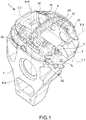
- a caliper and supporting assembly 1 for a disc brake 10 comprises a brake caliper 3 and a supporting element 4.
- an axial direction X-X is defined either coinciding with or parallel to the rotation axis of the disc 2 of the disc brake 10, a radial direction R-R orthogonal to the axial direction X-X, and a tangential T-T or circumferential direction T-T, orthogonal to both the axial direction X-X and to the radial direction R-R.
- Said brake caliper 3 comprises a caliper body 5, adapted to straddle an associable disc 2 of the disc brake 10.
- Said support element 4 is connected to the said caliper body 5.
- said supporting element 4 is adapted to connect to at least one arm of a vehicle suspension.
- said supporting element 4 is a hub carrier adapted to house a bearing for supporting a hub connectable to said disc 2 and to a wheel of the vehicle.
- said hub carrier delimits a hub housing 9 and is adapted to accommodate a bearing for supporting a hub connectable to said disc 2 and to a vehicle wheel.
- Said caliper body 5 comprises a first portion 7. According to an embodiment, said caliper body 5 is integral with said first portion 7. According to an embodiment, said caliper body 5 and said first portion 7 are made of separate parts made integral to each other.
- Said supporting element 4 comprises a second portion 8. According to an embodiment, said supporting element 4 is integral with said second portion 8. According to an embodiment, said caliper body 4 and said second portion 8 are made of separate parts made integral to each other.
- said first portion 7 faces said second portion 8. According to a preferred embodiment, said first portion 7 faces said second portion 8 in said predetermined direction T-T.
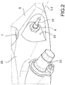
- said caliper and supporting assembly 1 comprises at least one detecting device 6 which detects a distance d at least along said predetermined direction T-T between said first portion 7 of the caliper body 5 and said second portion 8 of the supporting element 4.
- said at least one predetermined direction T-T is the tangential direction T-T.
- the distance d evaluated in the tangential direction T-T is proportional to the force with which the disc pushes the pads in the tangential direction T-T. In this manner, it is possible to quantify the braking action by evaluating the deformation in tangential direction T-T of at least one portion of the caliper body.
- said caliper body 5 comprises a first elongated portion 24, adapted to face, either directly or indirectly, by means of at least a first brake pad 31 a first braking surface of the disc 2, and an opposite second elongated portion 25 adapted to face, either directly or indirectly, by means of at least a second brake pad 32 a second braking surface of the disc 2, opposite to said first braking surface.
- said first elongated portion 24 is placed on one side of the caliper body 5 associated with said supporting structure 4.
- said first elongated portion 24 is placed on one side of the caliper body 5 associable with the vehicle by means of said supporting structure 4.
- said caliper body 5 comprises at least one caliper bridge 26 which connects said first elongated portion 24 and said second elongated portion 25 straddling the disc 2.
- said caliper body 5 comprises an inner caliper portion 27, adapted to face the disc 2 and an opposite outer caliper portion 28.
- said inner caliper portion 27 delimits a disc housing 9 adapted to receive a portion of the disc 2.
- At least either said first elongated portion 24 or said second elongated portion 25 delimits at least one thrust means housing 29 adapted to receive thrust means 15 adapted to press against the back of a brake pad 31, 32, preferably the back of a support plate 30 to the friction material 33 of an associable brake pad 31, 32.
- said brake caliper 3 comprises thrust means 15, e.g. cylinder-piston assemblies, adapted to press a brake pad 31, 32 and close it against the facing the braking surface of the disc 2.
- said brake caliper 3 comprises thrust means 15 exclusively associated with said second elongated portion 25, thereby avoiding to provide thrust means 15 associated with said first elongated portion 24.
- said brake caliper 3 comprises thrust means 15 associated with said first elongated portion 24 and with said second elongated portion 25.
- said brake caliper 3 comprises at least two opposite brake pads 31, 32, each comprising a friction material 33, adapted to press against opposite braking surfaces of the disc 2 during the braking action.
- each brake pad 31, 32 also comprises a supporting plate 30, adapted to support said friction material 33.
- each brake pad 31, 32 is made in one piece, e.g. of carbon.
- said caliper body comprises a disc inlet side 11 and a disc outlet side 12 opposite to said disc inlet side 11 in tangential direction T-T.
- the disc 2 rotates in a rotation direction V, a given portion of the disc entering into said disc housing 9 of the caliper body 5 from said disc inlet side 11 and exiting from the disc housing 9 from said disc outlet side 12.
- said caliper and supporting assembly 1 comprises at least one disc inlet side fixing device 34 which constrains said caliper body 5 with respect to said supporting element 4 along said predetermined direction T-T.
- said disc inlet side 11 of the caliper body 5 is associated with said disc inlet side fixing devices 34.
- Providing said disc inlet side fixing device 34 locally prevents the deformation of the caliper body 5, preferably on the disc inlet side of the caliper body, with respect to the supporting element 4 along said predetermined direction T-T.
- said caliper body 5 comprises a connecting portion 18 which couples with said supporting element 4, and wherein said connecting portion comprises said first portion 7 of the caliper body 5.
- said connecting portion 18 of the caliper body 5 couples with said supporting element 4, thereby avoiding the formation of a constraint along said at least one predetermined direction T-T, between said caliper body 5 and said supporting element 4. In this manner, the deformation of the caliper body 5 in said predetermined direction T-T is facilitated, without generating portions of elastic instability due to peak load in the caliper body 5.
- said supporting element 4 comprises a connecting counter-portion which couples with said caliper body 5, and wherein said connecting counter-portion comprises said second portion 8 of the supporting element 4.
- said connecting portion 18 of the caliper body 5 couples with said connecting counter-portion of the supporting element 4, thereby avoiding the formation of a constraint along said at least one predetermined direction T-T, between said caliper body 5 and said supporting element 4.
- said connecting portion 18 of the caliper body 5 cooperates with said connecting counter-portion of the supporting element 4, thereby forming a constraint in axial direction X-X between said caliper body 5 and said supporting element 4.
- said connecting portion of the caliper body 5 comprises at least one slot wall 13 which at least partly defines a slot 14.
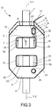
- said slot 14 receives a connecting device 20 of the supporting element 4 and describes a slot edge profile of shape elongated along said predetermined direction T-T, thereby avoiding the formation of a constraint between said caliper body 5 and said supporting element 4 in said predetermined direction T-T.
- said connection device 20 avoids abutting by moving along said predetermined direction T-T with respect to the caliper body 5 against said at least one wall of the slot 13.
- said slot 14 is arranged on said disc outlet side 12 of the caliper body 5.
- Providing such slot 14 allows said caliper body 5 to form a constraint substantially sliding along said predetermined direction T-T between a portion of the caliper body 5 and said supporting element 4.
- said connecting counter-portion of the supporting element 4 comprises a connecting device 20 which is received in said slot 14 of the caliper body 5.
- said at least one slot wall 13 comprises said first portion 7 of the caliper body 5.
- said connecting device 20 comprises said second portion 8 of the supporting element 4.
- said connecting device 20 of the supporting element 4 and of said slot 14 of the caliper body 5 couple with thereby avoiding the formation of a constraint along said at least one predetermined direction T-T, between said caliper body 5 and said supporting element 4.
- said connecting device 20 cooperates with said at least one slot wall 13 of said caliper body 5 forming a constraint in axial direction X-X between said caliper body 5 and said supporting element 4.
- said connecting device 20 comprises at least one stud bolt.
- said connecting device 20 comprises at least one bush fitted on said stud bolt.
- said bush slides against said at least one slot wall 13 during the braking action, thereby protecting said stud bolt from wear by friction, e.g. by sliding friction.
- Providing said bush also acts as a spacer to separate the tightening nut of the connecting device 20 from the caliper body, thereby avoiding preventing the friction exerted by the portion under the head of the tightening nut from obstructing or preventing deformation of the caliper body.
- said disc outlet side 12 of the caliper body 5 comprising said first portion 7.
- said disc inlet side fixing device 34 is substantially aligned to said connecting device 20 along said preferred direction T-T.
- the disc 2 applies on the brake pads 31, 32 a feeding action F, preferably directed substantially parallel to the rotation direction V of the disc 2, making the support plate 30 of at least one of said brake pads 31, 32 abut against a tangential abutment portion 35 of the caliper body 5.
- said feeding action is directed along said predetermined direction T-T. In this manner, the feeding action which elastically deforms along said predetermined direction T-T at least one portion of the caliper body 5 interposed between said disc inlet side fixing device 34 and said abutment portion 35.
- said detecting device 6 comprises at least one sensor 16.
- said sensor 16 is an eddy current sensor.
- said sensor 16 is an LVDT.
- said sensor 16 is integral with the caliper body 5.
- said sensor 16 is integral with said first portion 7 of the caliper body 5.
- said sensor 16 comprises said first portion 7 of the caliper body 5.
- said sensor 16 comprises an overhanging sensor portion 17 which overhangingly protrudes from said slot wall 13 into said slot 14 towards said connecting device 20.
- said overhanging portion of the sensor 17 extends substantially along said predetermined direction T-T.
- said sensor 16 comprises an output portion 19 of the sensor 16 adapted to connect with at least a data transmission wire 21.
- said detecting device 6 is associated with a data processing unit adapted to receive information on said tangential distance d to quantify the braking action and/or estimate the braking torque and/or calculate the braking force.
- said detecting device 6 is associated with a data processing unit by means of said data transmission wire 21.
- said brake caliper 3 comprises at least one brake fluid feeding pipe 22.
- said detecting device 6 is situated near said brake fluid feeding pipe 22.
- said data transmission wire 21 can favorably pass through the vehicle next to said brake fluid feeding pipe 22, thereby avoiding to provide an additional path dedicated to the data transmission wire 21.
- said caliper body 5 comprises a flattened surface 23 which extends on a plane perpendicular to said predetermined direction T-T.
- said flattened surface 23 extends over a portion of the caliper body 5 opposite to the disc 2 or unsuitable to face the disc 2.
- said outer caliper side 28 comprises said flattened surface 23.
- said flattened surface 23 of the caliper body 5 is made by removing material.
- said connecting portion 18 of the caliper body 5 comprises said flattened surface 23.
- said detecting device 6, preferably said sensor 16 is associated with said flattened surface 23.
- said outlet portion 19 of the sensor 16 overhangingly protrudes from the flattened surface 23.
- said brake caliper 3 is a fixed type caliper.
- said brake caliper 3 is a floating type caliper.
- a method for detecting the deformation of the caliper body during the braking action along a predetermined direction T-T comprises the following steps:
- the step of detecting a distance d along at least said predetermined direction T-T between said first portion 7 of the caliper body 5 and said second portion 8 of the supporting element 4 is performed by detecting said distance d at least along the tangential direction T-T.
- the step of detecting a distance d along at least said predetermined direction T-T between said first portion 7 of the caliper body 5 and said second portion 8 of the supporting element 4 is performed both during the braking action and in forward travel conditions.
- said method comprises the following additional step of comparing the distance detected in braking conditions with the distance detected in forward travel conditions.
- a caliper body 5 for a brake caliper 3 of a disc brake 10 is provided, wherein an axial direction X-X is defined, either coinciding with or parallel to the rotation axis of a disc 2 of the disc brake, a radial direction R-R orthogonal to the axial direction X-X, and a tangential T-T or direction T-T direction, orthogonal both to the axial direction X-X and to the radial direction R-R.
- Said caliper body 5 comprises a disc inlet side 11 and a disc outlet side 12 opposite to said disc inlet side 11 in the tangential direction T-T, wherein at least either said disc inlet side 11 or said disc outlet side 12, preferably said disc outlet side 12, comprises at least one slot wall 13 which at least partly defines a slot 14 adapted to receive a connecting device 20 for forming a connection between the caliper body 5 and an associable supporting element 4.
- Said slot 14 has an extension in tangential direction T-T greater than the dimension in tangential direction T-T of the connecting device 20, so as to define between at least one of said slot walls 13 and said connecting device 20 a predetermined tangential distance d, when said connection device 20 is accommodated in said slot 14, thereby allowing, during the braking action, at least one portion of the caliper body 5 to deform elastically in tangential direction T-T.
- At least one of said walls of slot 13 comprises at least one first portion 7 movable during the braking action in a tangential direction T-T with respect to a second portion 8 of the supporting element 4 associable with the caliper body 5.
- said caliper body 5 is associated with a detecting device 6 which is adapted to detect the tangential distance d between said slot wall 13 and said connecting device 20.
- a caliper and supporting assembly 1 for a disc brake comprises a brake caliper 3.
- Said brake caliper 3 comprising a caliper body 5, adapted to straddle an associable disc 2 of the disc brake.
- Said supporting element 4 comprises a second portion 8, e.g. a bracket which overhangingly protrudes towards said first elongated portion of the caliper body 24.
- the caliper body 5 elastically deforms according to at least one predetermined direction T-T, thereby determining the displacement in at least said predetermined direction T-T of the first portion 7 of the caliper body 5 with respect to said second portion 8 of the supporting element 4.
- Said caliper and supporting assembly 1 comprises at least one detecting device 6 fixed to said first portion 7 of the elongated element 24, which detects a distance "d" at least along said predetermined direction T-T between said first portion 7 of the caliper body 5 and said second portion 8 of the supporting element 4.
- a disc brake 10 is provided, in which the detecting device 6 is placed integral externally to an elongated element 24 of the caliper body 5 and faces a second portion 8 of the supporting element 4 provided in the supporting element 4 and is arranged overhanging it protruding towards the caliper body 5 facing the detecting device 6.
- a caliper and supporting assembly 1 for a disc brake comprises a brake caliper 3.
- Said brake caliper 3 comprising a caliper body 5, adapted to straddle an associable disc 2 of the disc brake.
- Said caliper and supporting assembly 1 further comprises a supporting element 4 connected to said caliper body 5.
- Said caliper body 5 comprises a first portion 7, e.g. an elongated element portion 24, e.g. a bracket which overhangingly protrudes towards said supporting element 4.
- Said supporting element 4 comprises a second portion 8.
- the caliper body 5 elastically deforms according to at least one predetermined direction T-T, thereby determining the displacement in at least said predetermined direction T-T of the first portion 7 of the caliper body 5 with respect to said second portion 8 of the supporting element 4.
- Said caliper and supporting assembly 1 comprises at least one detecting device 6 fixed to said second portion 8 of the supporting element 4, which detects a distance "d" at least along said predetermined direction T-T between said first portion 7 of the caliper body 5 and said second portion 8 of the supporting element 4.
- a disc brake 10 is provided in which the detecting device 6 is rigidly connected to the outside of the supporting element 4 and faces a first portion 7 which extends from an elongated element 24 of the caliper body 5 overhangingly placed on this elongated element 24 and projecting towards the supporting element 4 facing the detecting device 6.
Landscapes
- Engineering & Computer Science (AREA)
- General Engineering & Computer Science (AREA)
- Mechanical Engineering (AREA)
- Transportation (AREA)
- Braking Arrangements (AREA)
Claims (10)
- Bremssattel- und Halterungsanordnung (1) für eine Scheibenbremse, wobei eine axiale Richtung (X-X), welche entweder mit der Rotationsachse einer Scheibe (2) der Scheibenbremse zusammenfällt oder parallel dazu ist, eine radiale Richtung (R-R), welche orthogonal zu der axialen Richtung (X-X) ist, und eine tangentiale (T-T) oder Umfangs- (T-T) Richtung definiert sind, welche orthogonal sowohl zu der axialen Richtung (X-X) als auch zu der radialen Richtung (R-R) ist;- wobei die Bremssattel- und Halterungsanordnung (1) einen Bremssattel (3) umfasst, welcher einen Sattelkörper (5) umfasst, welcher dazu eingerichtet ist, eine zuordenbare Scheibe (2) der Scheibenbremse zu überspannen;- wobei die Bremssattel- und Halterungsanordnung (1) ein Halterungselement (4) umfasst, welches mit dem Sattelkörper (5) verbunden ist;
wobei- der Sattelkörper (5) einen ersten Abschnitt (7) umfasst;- wobei das Halterungselement (4) einen zweiten Abschnitt (8) umfasst;- wobei während der Bremswirkung der Sattelkörper (5) gemäß wenigstens einer vorbestimmten Richtung (T-T) elastisch verformt wird, wodurch die Verlagerung in wenigstens der vorbestimmten Richtung (T-T) des ersten Abschnitts (7) des Sattelkörpers (5) in Bezug auf den zweiten Abschnitt (8) des Halterungselements (4) bestimmt wird;- wobei die Bremssattel- und Halterungsanordnung (1) wenigstens eine Detektionsvorrichtung (6) umfasst, welche einen Abstand (d) entlang wenigstens der vorbestimmten Richtung (T-T) zwischen dem ersten Abschnitt (7) des Sattelkörpers (5) und dem zweiten Abschnitt (8) des Halterungselements (4) detektiert. - Bremssattel- und Halterungsanordnung (1) nach Anspruch 1, wobei die wenigstens eine vorbestimmte Richtung (T-T) die tangentiale Richtung (T-T) ist.
- Bremssattel- und Halterungsanordnung (1) nach Anspruch 1 oder 2, wobei der erste Abschnitt (7), vorzugsweise entlang der vorbestimmten Richtung (T-T), dem zweiten Abschnitt (8) zugewandt ist; und/oder wobeider Sattelkörper (5) einen Verbindungsabschnitt umfasst, welcher mit dem Halterungselement (4) gekoppelt ist, und wobei der Verbindungsabschnitt den ersten Abschnitt (7) des Sattelkörpers (5) umfasst; und/oder wobeider Verbindungsabschnitt des Sattelkörpers (5) mit dem Halterungselement (4) gekoppelt ist, wodurch die Bildung einer Einschränkung entlang der wenigstens einen vorbestimmten Richtung (T-T) zwischen dem Sattelkörper (5) und dem Halterungselement (4) verhindert wird; und/oder wobeidas Halterungselement (4) einen Verbindungsgegenabschnitt umfasst, welcher mit dem Sattelkörper (5) gekoppelt ist, und wobei der Verbindungsgegenabschnitt den zweiten Abschnitt (8) des Halterungselements (4) umfasst; und/oder wobeider Verbindungsabschnitt des Sattelkörpers (5) mit dem Verbindungsgegenabschnitt des Halterungselements (4) gekoppelt ist, wodurch die Bildung einer Einschränkung entlang der wenigstens einen vorbestimmten Richtung (T-T) zwischen dem Sattelkörper (5) und dem Halterungselement (4) verhindert wird.
- Bremssattel- und Halterungsanordnung (1) nach einem der vorhergehenden Ansprüche, wobei der Verbindungsabschnitt des Sattelkörpers (5) wenigstens eine Schlitzwand (13) umfasst, welche wenigstens teilweise einen Schlitz (14) definiert; und/oder wobeider Verbindungsgegenabschnitt des Halterungselements (4) eine Verbindungsvorrichtung (20) umfasst, welche in dem Schlitz (14) des Sattelkörpers (5) aufgenommen ist; und/oder wobeidie wenigstens eine Schlitzwand (13) den ersten Abschnitt (7) des Sattelkörpers (5) umfasst; und/oder wobeidie Verbindungsvorrichtung (20) den zweiten Abschnitt (8) des Halterungselements (4) umfasst; und/oder wobeidie Verbindungsvorrichtung (20) des Halterungselements (4) und des Schlitzes (14) des Sattelkörpers (5) gekoppelt sind, wodurch die Bildung einer Einschränkung entlang der wenigstens einen vorbestimmten Richtung (T-T) zwischen dem Sattelkörper (5) und dem Halterungselement (4) verhindert wird; und/oder wobeidie Verbindungsvorrichtung (20) wenigstens einen Stehbolzen (13) umfasst; und/oder wobeidie Verbindungsvorrichtung (20) wenigstens eine Buchse umfasst, welche auf den Stehbolzen (13) montiert ist; und/oder wobeidie Verbindungsvorrichtung (20) mit der wenigstens einen Schlitzwand (13) des Sattelkörpers (5) zusammenwirkt, wodurch eine Einschränkung in axialer Richtung (X-X) zwischen dem Sattelkörper (5) und dem Halterungselement (4) gebildet wird.
- Bremssattel- und Halterungsanordnung (1) nach einem der vorhergehenden Ansprüche, wobei die Detektionsvorrichtung (6) wenigstens einen Sensor (16) umfasst; und/oder wobeider Sensor (16) ein Wirbelstrom- und/oder LVDT-Sensor ist; und/oder wobeider Sensor (16) integral mit dem Sattelkörper (5) ist; und/oder wobei der Sensor (16) integral mit dem ersten Abschnitt (7) des Sattelkörpers (5) ist; und/oder wobeider Sensor (16) den ersten Abschnitt (7) des Sattelkörpers (5) umfasst; und/oder wobeider Sensor (16) einen vorstehenden Abschnitt des Sensors (17) umfasst, welcher überhängend von der Schlitzwand (13) in den Schlitz (14) in Richtung der Verbindungsvorrichtung (20) vorsteht; und/oder wobeisich der überhängende Abschnitt des Sensors (17) im Wesentlichen entlang der vorbestimmten Richtung (T-T) erstreckt.
- Bremssattel- und Halterungsanordnung (1) nach einem der vorhergehenden Ansprüche, wobei der Sattelkörper (5) eine abgeflachte Fläche (23) umfasst, welche sich auf einer Ebene erstreckt, welche senkrecht zu der vorbestimmten Richtung (T-T) ist; und/oder wobeisich die abgeflachte Fläche (23) über einen Abschnitt des Sattelkörpers (5) erstreckt, welcher der Scheibe (2) entgegengesetzt ist oder ungeeignet ist, der Scheibe (2) zugewandt zu sein; und/oder wobeidie abgeflachte Fläche (23) des Sattelkörpers (5) durch Entfernen von Material hergestellt ist; und/oder wobeider Verbindungsabschnitt (18) des Sattelkörpers (5) die abgeflachte Fläche (23) umfasst; und/oder wobeidie Detektionsvorrichtung (6) der abgeflachten Fläche (23) zugeordnet ist; und/oder wobeider Ausgangsabschnitt (19) des Sensors (16) überhängend von der abgeflachten Fläche (23) vorsteht.
- Bremssattel- und Halterungsanordnung (1) nach einem der vorhergehenden Ansprüche, wobei das Halterungselement (4) ein Nabenträger (9) ist, welcher dazu eingerichtet ist, ein Lager zum Haltern einer Nabe unterzubringen, welche mit der Scheibe (2) und mit einem Rad des Fahrzeugs verbindbar ist; und/oder wobei
die Detektionsvorrichtung (6) einer Datenverarbeitungseinheit zugeordnet ist, welche dazu eingerichtet ist, Informationen über den tangentialen Abstand (d) zu empfangen, um die Bremswirkung zu quantifizieren und/oder das Bremsmoment abzuschätzen und/oder die Bremskraft zu berechnen. - Bremssattel- und Halterungsanordnung (1) nach einem der vorhergehenden Ansprüche, wobei der Bremssattel (3) ein fixierter Bremssattel ist;und/oder wobeidie Detektionsvorrichtung (6) integral außerhalb eines länglichen Elements (24) des Sattelkörpers (5) platziert ist und einem zweiten Abschnitt (8) des Halterungselements (4) zugewandt ist, welcher in dem Halterungselement (4) bereitgestellt ist, und es überhängend in Richtung des Sattelkörpers (5) vorstehend angeordnet ist, welcher der Detektionsvorrichtung (6) zugewandt ist;und/oder wobeidie Detektionsvorrichtung (6) integral außerhalb des Halterungselements (4) platziert ist und einem ersten Abschnitt (7) zugewandt ist, welcher sich von einem länglichen Element (24) des Sattelkörpers (5) erstreckt, welcher überhängend an diesem länglichen Element (24) platziert ist und in Richtung des Halterungselements (4) vorsteht, welches der Detektionsvorrichtung (6) zugewandt ist.
- Verfahren zum Detektieren der Verformung des Bremssattelkörpers während der Bremswirkung entlang einer vorbestimmten Richtung (T-T), umfassend die folgenden Schritte:- Bereitstellen einer Bremssattel- und Halterungsanordnung (1), wobei die Anordnung des Bremssattels und der Halterung (1) einen Bremssattel (3) umfasst, welcher einen Sattelkörper (5) und ein Halterungselement (4) umfasst, welches mit dem Sattelkörper (5) verbunden ist;- Identifizieren eines ersten Abschnitts des Sattelkörpers (7), welcher sich während der Bremswirkung in Bezug auf einen zweiten Abschnitt des Halterungselements (8) bewegt;- Detektieren eines Abstands (d) entlang wenigstens der vorbestimmten Richtung (T-T) zwischen dem ersten Abschnitt (7) des Sattelkörpers (5) und dem zweiten Abschnitt (8) des Halterungselements (4).
- Verfahren nach Anspruch 9, umfassend wenigstens einen, aber möglicherweise alle, der folgenden weiteren Schritte:- Detektieren des Abstands (d) entlang wenigstens der Richtung (T-T) zwischen dem ersten Abschnitt (7) des Bremssattels (5) und dem zweiten Abschnitt (8) des Halterungselements (4); und/oder- Detektieren des Abstands (d) sowohl während der Bremswirkung als auch bei Vorwärtsfahrtzuständen; und/oder- Vergleichen des detektierten Abstands bei Bremszuständen mit dem detektierten Abstand bei Vorwärtsfahrtzuständen.
Applications Claiming Priority (2)
| Application Number | Priority Date | Filing Date | Title |
|---|---|---|---|
| IT102017000075649A IT201700075649A1 (it) | 2017-07-05 | 2017-07-05 | Assieme di pinza e supporto e metodo |
| PCT/IB2018/054972 WO2019008534A1 (en) | 2017-07-05 | 2018-07-05 | CALIPER ASSEMBLY AND SUPPORT AND METHOD FOR DETECTING CALIPER DEFORMATION |
Publications (2)
| Publication Number | Publication Date |
|---|---|
| EP3649366A1 EP3649366A1 (de) | 2020-05-13 |
| EP3649366B1 true EP3649366B1 (de) | 2021-03-03 |
Family
ID=60294307
Family Applications (1)
| Application Number | Title | Priority Date | Filing Date |
|---|---|---|---|
| EP18749553.6A Active EP3649366B1 (de) | 2017-07-05 | 2018-07-05 | Bremssattel mit abstützung und bremssatteldeformationsdetektionsverfahren |
Country Status (7)
| Country | Link |
|---|---|
| US (1) | US11209055B2 (de) |
| EP (1) | EP3649366B1 (de) |
| JP (1) | JP7239498B2 (de) |
| CN (1) | CN110832219B (de) |
| ES (1) | ES2875779T3 (de) |
| IT (1) | IT201700075649A1 (de) |
| WO (1) | WO2019008534A1 (de) |
Families Citing this family (4)
| Publication number | Priority date | Publication date | Assignee | Title |
|---|---|---|---|---|
| CN111521318B (zh) * | 2020-05-26 | 2025-03-28 | 石家庄五龙制动器股份有限公司 | 制动器制动力矩传感器 |
| GB2614226B (en) | 2021-09-14 | 2026-03-18 | Ap Racing Ltd | Braking system |
| IT202100030617A1 (it) | 2021-12-03 | 2023-06-03 | Brembo Spa | Assieme di pinza e supporto e metodo |
| IT202200006218A1 (it) * | 2022-03-30 | 2023-09-30 | Brembo Spa | Corpo pinza per pinza freno, pinza freno e freno a disco |
Family Cites Families (17)
| Publication number | Priority date | Publication date | Assignee | Title |
|---|---|---|---|---|
| JPH0678057B2 (ja) * | 1985-04-25 | 1994-10-05 | 富士重工業株式会社 | ブレ−キ装置 |
| IT1276023B1 (it) * | 1995-03-13 | 1997-10-24 | Freni Brembo Spa | Freno a disco |
| US6247560B1 (en) * | 1996-12-12 | 2001-06-19 | Federal-Mogul Technology Limited | Slidable brake disc system |
| US6511135B2 (en) * | 1999-12-14 | 2003-01-28 | Delphi Technologies, Inc. | Disk brake mounting bracket and high gain torque sensor |
| US6668983B2 (en) | 2001-12-18 | 2003-12-30 | Delphi Technologies, Inc. | Wheel brake caliper with integral brake pad torque sensing |
| JP4074985B2 (ja) | 2002-08-30 | 2008-04-16 | 株式会社日立製作所 | ディスクブレーキ |
| DE102005013142A1 (de) | 2005-03-22 | 2006-09-28 | Robert Bosch Gmbh | Bremskraftmessvorrichtung für eine Reibungsbremse |
| EP1748213A1 (de) * | 2005-07-25 | 2007-01-31 | Siemens Aktiengesellschaft | Scheibenbremse mit verbesserter Einrichtung zum Messen der wirkenden Normalkraft |
| DE102006029978B3 (de) * | 2006-06-29 | 2007-11-08 | Siemens Ag | Verfahren und eine Vorrichtung zum Messen einer wirkenden Normalkraft an einer Scheibenbremse |
| US7813860B2 (en) * | 2006-09-22 | 2010-10-12 | Honda Motor Co., Ltd. | Brake force detecting device |
| JP4769674B2 (ja) | 2006-09-22 | 2011-09-07 | 本田技研工業株式会社 | ブレーキ力検出装置 |
| DE102008042298A1 (de) | 2008-09-23 | 2010-03-25 | Robert Bosch Gmbh | Bremssattel für eine Scheibenbremse |
| DE102009041951B4 (de) * | 2009-09-17 | 2020-04-02 | Knorr-Bremse Systeme für Nutzfahrzeuge GmbH | Messanordnung zur Zuspannkraftmessung einer Scheibenbremse und eine entsprechende Scheibenbremse |
| IT1402864B1 (it) * | 2010-11-05 | 2013-09-27 | Freni Brembo Spa | Assieme di corpo pinza di un freno a disco e portamozzo |
| DE102012007118B4 (de) * | 2012-04-05 | 2014-08-28 | Audi Ag | Vorrichtung zur Messung von Restbremsmomenten einer Scheibenbremse eines Kraftfahrzeugs |
| DE102013213619A1 (de) * | 2013-07-11 | 2015-01-15 | Siemens Aktiengesellschaft | Bremszuspanneinrichtung für eine Scheiben-Bremsvorrichtung |
| CN106314415B (zh) * | 2016-08-29 | 2019-10-22 | 北汽福田汽车股份有限公司 | 行车制动装置的检测系统及车辆 |
-
2017
- 2017-07-05 IT IT102017000075649A patent/IT201700075649A1/it unknown
-
2018
- 2018-07-05 JP JP2019571934A patent/JP7239498B2/ja active Active
- 2018-07-05 US US16/625,946 patent/US11209055B2/en active Active
- 2018-07-05 CN CN201880045102.1A patent/CN110832219B/zh active Active
- 2018-07-05 EP EP18749553.6A patent/EP3649366B1/de active Active
- 2018-07-05 WO PCT/IB2018/054972 patent/WO2019008534A1/en not_active Ceased
- 2018-07-05 ES ES18749553T patent/ES2875779T3/es active Active
Non-Patent Citations (1)
| Title |
|---|
| None * |
Also Published As
| Publication number | Publication date |
|---|---|
| ES2875779T3 (es) | 2021-11-11 |
| WO2019008534A1 (en) | 2019-01-10 |
| JP7239498B2 (ja) | 2023-03-14 |
| US20200158197A1 (en) | 2020-05-21 |
| IT201700075649A1 (it) | 2019-01-05 |
| CN110832219B (zh) | 2022-11-18 |
| CN110832219A (zh) | 2020-02-21 |
| US11209055B2 (en) | 2021-12-28 |
| JP2020525732A (ja) | 2020-08-27 |
| EP3649366A1 (de) | 2020-05-13 |
Similar Documents
| Publication | Publication Date | Title |
|---|---|---|
| US20070228815A1 (en) | Brake force detecting apparatus | |
| EP3649366B1 (de) | Bremssattel mit abstützung und bremssatteldeformationsdetektionsverfahren | |
| US8437934B2 (en) | Temperature and wear and tear sensor for brake or clutch devices | |
| US7813860B2 (en) | Brake force detecting device | |
| US9765833B2 (en) | Anti-lock brake device for use with a brake rotor disc | |
| CN110614988B (zh) | 车辆制动系统及其操作方法、计算机程序产品和控制单元 | |
| US20090320579A1 (en) | Method and device for measuring an effective normal force on a disk brake | |
| US9394954B2 (en) | Guide pin for disc brake assembly and disc brake assembly including such a guide pin | |
| US20090055065A1 (en) | Active Brake Pulsation Control | |
| CN113906232A (zh) | 盘式制动器的制动卡钳、盘式制动系统及检测装置 | |
| US20250020178A1 (en) | Caliper and support assembly, and method | |
| US9284999B2 (en) | Guide pin for disc brake assembly, disc brake assembly including such a guide pin and method for producing a disc brake assembly including such a guide pin | |
| US20080078629A1 (en) | Brake force detecting device | |
| US10773703B2 (en) | Assembly for measuring a displacement distance produced by a braking force | |
| WO2010005379A1 (en) | Method and system for monitoring the lining clearance in a disc brake or drum brake | |
| EP1730414B1 (de) | Erfassungssystem für scheibenbremse | |
| JP2004092770A (ja) | ディスクブレーキ | |
| JP4620073B2 (ja) | ブレーキ力検出装置 | |
| JP4755559B2 (ja) | ブレーキ力検出装置 | |
| JP2022040741A (ja) | 車両用ディスクブレーキ | |
| CN119900778A (zh) | 设定盘式制动器的间隙的方法、制动衬块和行车制动器 | |
| JP2022040742A (ja) | 車両用ディスクブレーキ | |
| KR100505867B1 (ko) | 진동 개선용 자동차 켈리퍼 조립체 | |
| JP2000241341A (ja) | 摩擦力測定装置 |
Legal Events
| Date | Code | Title | Description |
|---|---|---|---|
| STAA | Information on the status of an ep patent application or granted ep patent |
Free format text: STATUS: UNKNOWN |
|
| STAA | Information on the status of an ep patent application or granted ep patent |
Free format text: STATUS: THE INTERNATIONAL PUBLICATION HAS BEEN MADE |
|
| PUAI | Public reference made under article 153(3) epc to a published international application that has entered the european phase |
Free format text: ORIGINAL CODE: 0009012 |
|
| STAA | Information on the status of an ep patent application or granted ep patent |
Free format text: STATUS: REQUEST FOR EXAMINATION WAS MADE |
|
| 17P | Request for examination filed |
Effective date: 20191219 |
|
| AK | Designated contracting states |
Kind code of ref document: A1 Designated state(s): AL AT BE BG CH CY CZ DE DK EE ES FI FR GB GR HR HU IE IS IT LI LT LU LV MC MK MT NL NO PL PT RO RS SE SI SK SM TR |
|
| AX | Request for extension of the european patent |
Extension state: BA ME |
|
| DAV | Request for validation of the european patent (deleted) | ||
| DAX | Request for extension of the european patent (deleted) | ||
| GRAP | Despatch of communication of intention to grant a patent |
Free format text: ORIGINAL CODE: EPIDOSNIGR1 |
|
| STAA | Information on the status of an ep patent application or granted ep patent |
Free format text: STATUS: GRANT OF PATENT IS INTENDED |
|
| INTG | Intention to grant announced |
Effective date: 20201028 |
|
| RIN1 | Information on inventor provided before grant (corrected) |
Inventor name: CANTONI, CARLO Inventor name: COMENDULI, ALBERTO Inventor name: ARIENTI, ROBERTO Inventor name: MESCHINI, ANDREA |
|
| GRAS | Grant fee paid |
Free format text: ORIGINAL CODE: EPIDOSNIGR3 |
|
| GRAA | (expected) grant |
Free format text: ORIGINAL CODE: 0009210 |
|
| STAA | Information on the status of an ep patent application or granted ep patent |
Free format text: STATUS: THE PATENT HAS BEEN GRANTED |
|
| AK | Designated contracting states |
Kind code of ref document: B1 Designated state(s): AL AT BE BG CH CY CZ DE DK EE ES FI FR GB GR HR HU IE IS IT LI LT LU LV MC MK MT NL NO PL PT RO RS SE SI SK SM TR |
|
| REG | Reference to a national code |
Ref country code: GB Ref legal event code: FG4D |
|
| REG | Reference to a national code |
Ref country code: AT Ref legal event code: REF Ref document number: 1367546 Country of ref document: AT Kind code of ref document: T Effective date: 20210315 Ref country code: CH Ref legal event code: EP |
|
| REG | Reference to a national code |
Ref country code: DE Ref legal event code: R096 Ref document number: 602018013489 Country of ref document: DE |
|
| REG | Reference to a national code |
Ref country code: IE Ref legal event code: FG4D |
|
| REG | Reference to a national code |
Ref country code: CH Ref legal event code: PK Free format text: BERICHTIGUNGEN |
|
| REG | Reference to a national code |
Ref country code: LT Ref legal event code: MG9D |
|
| REG | Reference to a national code |
Ref country code: DE Ref legal event code: R081 Ref document number: 602018013489 Country of ref document: DE Owner name: BREMBO S.P.A., CURNO, IT Free format text: FORMER OWNER: FRENI BREMBO S.P.A., CURNO, BERGAMO, IT |
|
| RIN2 | Information on inventor provided after grant (corrected) |
Inventor name: COMENDULI, ALBERTO Inventor name: MESCHINI, ANDREA Inventor name: CANTONI, CARLO Inventor name: ARIENTI, ROBERTO |
|
| RAP4 | Party data changed (patent owner data changed or rights of a patent transferred) |
Owner name: BREMBO S.P.A. |
|
| PG25 | Lapsed in a contracting state [announced via postgrant information from national office to epo] |
Ref country code: BG Free format text: LAPSE BECAUSE OF FAILURE TO SUBMIT A TRANSLATION OF THE DESCRIPTION OR TO PAY THE FEE WITHIN THE PRESCRIBED TIME-LIMIT Effective date: 20210603 Ref country code: FI Free format text: LAPSE BECAUSE OF FAILURE TO SUBMIT A TRANSLATION OF THE DESCRIPTION OR TO PAY THE FEE WITHIN THE PRESCRIBED TIME-LIMIT Effective date: 20210303 Ref country code: GR Free format text: LAPSE BECAUSE OF FAILURE TO SUBMIT A TRANSLATION OF THE DESCRIPTION OR TO PAY THE FEE WITHIN THE PRESCRIBED TIME-LIMIT Effective date: 20210604 Ref country code: HR Free format text: LAPSE BECAUSE OF FAILURE TO SUBMIT A TRANSLATION OF THE DESCRIPTION OR TO PAY THE FEE WITHIN THE PRESCRIBED TIME-LIMIT Effective date: 20210303 Ref country code: NO Free format text: LAPSE BECAUSE OF FAILURE TO SUBMIT A TRANSLATION OF THE DESCRIPTION OR TO PAY THE FEE WITHIN THE PRESCRIBED TIME-LIMIT Effective date: 20210603 Ref country code: LT Free format text: LAPSE BECAUSE OF FAILURE TO SUBMIT A TRANSLATION OF THE DESCRIPTION OR TO PAY THE FEE WITHIN THE PRESCRIBED TIME-LIMIT Effective date: 20210303 |
|
| REG | Reference to a national code |
Ref country code: NL Ref legal event code: MP Effective date: 20210303 |
|
| PG25 | Lapsed in a contracting state [announced via postgrant information from national office to epo] |
Ref country code: SE Free format text: LAPSE BECAUSE OF FAILURE TO SUBMIT A TRANSLATION OF THE DESCRIPTION OR TO PAY THE FEE WITHIN THE PRESCRIBED TIME-LIMIT Effective date: 20210303 Ref country code: PL Free format text: LAPSE BECAUSE OF FAILURE TO SUBMIT A TRANSLATION OF THE DESCRIPTION OR TO PAY THE FEE WITHIN THE PRESCRIBED TIME-LIMIT Effective date: 20210303 Ref country code: LV Free format text: LAPSE BECAUSE OF FAILURE TO SUBMIT A TRANSLATION OF THE DESCRIPTION OR TO PAY THE FEE WITHIN THE PRESCRIBED TIME-LIMIT Effective date: 20210303 Ref country code: RS Free format text: LAPSE BECAUSE OF FAILURE TO SUBMIT A TRANSLATION OF THE DESCRIPTION OR TO PAY THE FEE WITHIN THE PRESCRIBED TIME-LIMIT Effective date: 20210303 |
|
| RAP4 | Party data changed (patent owner data changed or rights of a patent transferred) |
Owner name: BREMBO S.P.A. |
|
| PG25 | Lapsed in a contracting state [announced via postgrant information from national office to epo] |
Ref country code: NL Free format text: LAPSE BECAUSE OF FAILURE TO SUBMIT A TRANSLATION OF THE DESCRIPTION OR TO PAY THE FEE WITHIN THE PRESCRIBED TIME-LIMIT Effective date: 20210303 |
|
| PG25 | Lapsed in a contracting state [announced via postgrant information from national office to epo] |
Ref country code: SM Free format text: LAPSE BECAUSE OF FAILURE TO SUBMIT A TRANSLATION OF THE DESCRIPTION OR TO PAY THE FEE WITHIN THE PRESCRIBED TIME-LIMIT Effective date: 20210303 Ref country code: EE Free format text: LAPSE BECAUSE OF FAILURE TO SUBMIT A TRANSLATION OF THE DESCRIPTION OR TO PAY THE FEE WITHIN THE PRESCRIBED TIME-LIMIT Effective date: 20210303 Ref country code: CZ Free format text: LAPSE BECAUSE OF FAILURE TO SUBMIT A TRANSLATION OF THE DESCRIPTION OR TO PAY THE FEE WITHIN THE PRESCRIBED TIME-LIMIT Effective date: 20210303 |
|
| REG | Reference to a national code |
Ref country code: ES Ref legal event code: FG2A Ref document number: 2875779 Country of ref document: ES Kind code of ref document: T3 Effective date: 20211111 |
|
| PG25 | Lapsed in a contracting state [announced via postgrant information from national office to epo] |
Ref country code: SK Free format text: LAPSE BECAUSE OF FAILURE TO SUBMIT A TRANSLATION OF THE DESCRIPTION OR TO PAY THE FEE WITHIN THE PRESCRIBED TIME-LIMIT Effective date: 20210303 Ref country code: PT Free format text: LAPSE BECAUSE OF FAILURE TO SUBMIT A TRANSLATION OF THE DESCRIPTION OR TO PAY THE FEE WITHIN THE PRESCRIBED TIME-LIMIT Effective date: 20210705 Ref country code: RO Free format text: LAPSE BECAUSE OF FAILURE TO SUBMIT A TRANSLATION OF THE DESCRIPTION OR TO PAY THE FEE WITHIN THE PRESCRIBED TIME-LIMIT Effective date: 20210303 Ref country code: IS Free format text: LAPSE BECAUSE OF FAILURE TO SUBMIT A TRANSLATION OF THE DESCRIPTION OR TO PAY THE FEE WITHIN THE PRESCRIBED TIME-LIMIT Effective date: 20210703 |
|
| REG | Reference to a national code |
Ref country code: DE Ref legal event code: R097 Ref document number: 602018013489 Country of ref document: DE |
|
| PLBE | No opposition filed within time limit |
Free format text: ORIGINAL CODE: 0009261 |
|
| STAA | Information on the status of an ep patent application or granted ep patent |
Free format text: STATUS: NO OPPOSITION FILED WITHIN TIME LIMIT |
|
| PG25 | Lapsed in a contracting state [announced via postgrant information from national office to epo] |
Ref country code: AL Free format text: LAPSE BECAUSE OF FAILURE TO SUBMIT A TRANSLATION OF THE DESCRIPTION OR TO PAY THE FEE WITHIN THE PRESCRIBED TIME-LIMIT Effective date: 20210303 Ref country code: DK Free format text: LAPSE BECAUSE OF FAILURE TO SUBMIT A TRANSLATION OF THE DESCRIPTION OR TO PAY THE FEE WITHIN THE PRESCRIBED TIME-LIMIT Effective date: 20210303 |
|
| 26N | No opposition filed |
Effective date: 20211206 |
|
| REG | Reference to a national code |
Ref country code: CH Ref legal event code: PL |
|
| PG25 | Lapsed in a contracting state [announced via postgrant information from national office to epo] |
Ref country code: MC Free format text: LAPSE BECAUSE OF FAILURE TO SUBMIT A TRANSLATION OF THE DESCRIPTION OR TO PAY THE FEE WITHIN THE PRESCRIBED TIME-LIMIT Effective date: 20210303 |
|
| REG | Reference to a national code |
Ref country code: BE Ref legal event code: MM Effective date: 20210731 |
|
| PG25 | Lapsed in a contracting state [announced via postgrant information from national office to epo] |
Ref country code: LI Free format text: LAPSE BECAUSE OF NON-PAYMENT OF DUE FEES Effective date: 20210731 Ref country code: IT Free format text: LAPSE BECAUSE OF FAILURE TO SUBMIT A TRANSLATION OF THE DESCRIPTION OR TO PAY THE FEE WITHIN THE PRESCRIBED TIME-LIMIT Effective date: 20210303 Ref country code: CH Free format text: LAPSE BECAUSE OF NON-PAYMENT OF DUE FEES Effective date: 20210731 |
|
| PG25 | Lapsed in a contracting state [announced via postgrant information from national office to epo] |
Ref country code: IS Free format text: LAPSE BECAUSE OF FAILURE TO SUBMIT A TRANSLATION OF THE DESCRIPTION OR TO PAY THE FEE WITHIN THE PRESCRIBED TIME-LIMIT Effective date: 20210703 Ref country code: LU Free format text: LAPSE BECAUSE OF NON-PAYMENT OF DUE FEES Effective date: 20210705 |
|
| PG25 | Lapsed in a contracting state [announced via postgrant information from national office to epo] |
Ref country code: IE Free format text: LAPSE BECAUSE OF NON-PAYMENT OF DUE FEES Effective date: 20210705 Ref country code: BE Free format text: LAPSE BECAUSE OF NON-PAYMENT OF DUE FEES Effective date: 20210731 |
|
| PG25 | Lapsed in a contracting state [announced via postgrant information from national office to epo] |
Ref country code: CY Free format text: LAPSE BECAUSE OF FAILURE TO SUBMIT A TRANSLATION OF THE DESCRIPTION OR TO PAY THE FEE WITHIN THE PRESCRIBED TIME-LIMIT Effective date: 20210303 |
|
| P01 | Opt-out of the competence of the unified patent court (upc) registered |
Effective date: 20230526 |
|
| PG25 | Lapsed in a contracting state [announced via postgrant information from national office to epo] |
Ref country code: HU Free format text: LAPSE BECAUSE OF FAILURE TO SUBMIT A TRANSLATION OF THE DESCRIPTION OR TO PAY THE FEE WITHIN THE PRESCRIBED TIME-LIMIT; INVALID AB INITIO Effective date: 20180705 |
|
| PG25 | Lapsed in a contracting state [announced via postgrant information from national office to epo] |
Ref country code: SI Free format text: LAPSE BECAUSE OF FAILURE TO SUBMIT A TRANSLATION OF THE DESCRIPTION OR TO PAY THE FEE WITHIN THE PRESCRIBED TIME-LIMIT Effective date: 20210303 |
|
| REG | Reference to a national code |
Ref country code: AT Ref legal event code: UEP Ref document number: 1367546 Country of ref document: AT Kind code of ref document: T Effective date: 20210303 |
|
| PG25 | Lapsed in a contracting state [announced via postgrant information from national office to epo] |
Ref country code: MK Free format text: LAPSE BECAUSE OF FAILURE TO SUBMIT A TRANSLATION OF THE DESCRIPTION OR TO PAY THE FEE WITHIN THE PRESCRIBED TIME-LIMIT Effective date: 20210303 |
|
| PG25 | Lapsed in a contracting state [announced via postgrant information from national office to epo] |
Ref country code: MT Free format text: LAPSE BECAUSE OF FAILURE TO SUBMIT A TRANSLATION OF THE DESCRIPTION OR TO PAY THE FEE WITHIN THE PRESCRIBED TIME-LIMIT Effective date: 20210303 |
|
| PGFP | Annual fee paid to national office [announced via postgrant information from national office to epo] |
Ref country code: ES Payment date: 20250801 Year of fee payment: 8 |
|
| PGFP | Annual fee paid to national office [announced via postgrant information from national office to epo] |
Ref country code: DE Payment date: 20250725 Year of fee payment: 8 |
|
| PGFP | Annual fee paid to national office [announced via postgrant information from national office to epo] |
Ref country code: GB Payment date: 20250722 Year of fee payment: 8 |
|
| PGFP | Annual fee paid to national office [announced via postgrant information from national office to epo] |
Ref country code: AT Payment date: 20250718 Year of fee payment: 8 Ref country code: FR Payment date: 20250731 Year of fee payment: 8 |
|
| PG25 | Lapsed in a contracting state [announced via postgrant information from national office to epo] |
Ref country code: TR Free format text: LAPSE BECAUSE OF FAILURE TO SUBMIT A TRANSLATION OF THE DESCRIPTION OR TO PAY THE FEE WITHIN THE PRESCRIBED TIME-LIMIT Effective date: 20210303 |