EP3649770B1 - Halterungsanordnung für mobile endgeräte - Google Patents
Halterungsanordnung für mobile endgeräte Download PDFInfo
- Publication number
- EP3649770B1 EP3649770B1 EP18759542.6A EP18759542A EP3649770B1 EP 3649770 B1 EP3649770 B1 EP 3649770B1 EP 18759542 A EP18759542 A EP 18759542A EP 3649770 B1 EP3649770 B1 EP 3649770B1
- Authority
- EP
- European Patent Office
- Prior art keywords
- holder
- designed
- main surface
- arrangement according
- connection
- Prior art date
- Legal status (The legal status is an assumption and is not a legal conclusion. Google has not performed a legal analysis and makes no representation as to the accuracy of the status listed.)
- Active
Links
Images




Classifications
-
- H—ELECTRICITY
- H04—ELECTRIC COMMUNICATION TECHNIQUE
- H04M—TELEPHONIC COMMUNICATION
- H04M1/00—Substation equipment, e.g. for use by subscribers
- H04M1/02—Constructional features of telephone sets
- H04M1/04—Supports for telephone transmitters or receivers
-
- B—PERFORMING OPERATIONS; TRANSPORTING
- B60—VEHICLES IN GENERAL
- B60R—VEHICLES, VEHICLE FITTINGS, OR VEHICLE PARTS, NOT OTHERWISE PROVIDED FOR
- B60R11/00—Arrangements for holding or mounting articles, not otherwise provided for
- B60R11/02—Arrangements for holding or mounting articles, not otherwise provided for for radio sets, television sets, telephones, or the like; Arrangement of controls thereof
-
- G—PHYSICS
- G06—COMPUTING OR CALCULATING; COUNTING
- G06F—ELECTRIC DIGITAL DATA PROCESSING
- G06F1/00—Details not covered by groups G06F3/00 - G06F13/00 and G06F21/00
- G06F1/16—Constructional details or arrangements
- G06F1/1613—Constructional details or arrangements for portable computers
- G06F1/1626—Constructional details or arrangements for portable computers with a single-body enclosure integrating a flat display, e.g. Personal Digital Assistants [PDAs]
-
- G—PHYSICS
- G06—COMPUTING OR CALCULATING; COUNTING
- G06F—ELECTRIC DIGITAL DATA PROCESSING
- G06F1/00—Details not covered by groups G06F3/00 - G06F13/00 and G06F21/00
- G06F1/16—Constructional details or arrangements
- G06F1/1613—Constructional details or arrangements for portable computers
- G06F1/1632—External expansion units, e.g. docking stations
-
- H—ELECTRICITY
- H04—ELECTRIC COMMUNICATION TECHNIQUE
- H04B—TRANSMISSION
- H04B1/00—Details of transmission systems, not covered by a single one of groups H04B3/00 - H04B13/00; Details of transmission systems not characterised by the medium used for transmission
- H04B1/38—Transceivers, i.e. devices in which transmitter and receiver form a structural unit and in which at least one part is used for functions of transmitting and receiving
- H04B1/3827—Portable transceivers
- H04B1/3877—Arrangements for enabling portable transceivers to be used in a fixed position, e.g. cradles or boosters
-
- B—PERFORMING OPERATIONS; TRANSPORTING
- B60—VEHICLES IN GENERAL
- B60R—VEHICLES, VEHICLE FITTINGS, OR VEHICLE PARTS, NOT OTHERWISE PROVIDED FOR
- B60R11/00—Arrangements for holding or mounting articles, not otherwise provided for
- B60R2011/0042—Arrangements for holding or mounting articles, not otherwise provided for characterised by mounting means
- B60R2011/0049—Arrangements for holding or mounting articles, not otherwise provided for characterised by mounting means for non integrated articles
- B60R2011/0064—Connection with the article
- B60R2011/0071—Connection with the article using latches, clips, clamps, straps or the like
-
- B—PERFORMING OPERATIONS; TRANSPORTING
- B60—VEHICLES IN GENERAL
- B60R—VEHICLES, VEHICLE FITTINGS, OR VEHICLE PARTS, NOT OTHERWISE PROVIDED FOR
- B60R11/00—Arrangements for holding or mounting articles, not otherwise provided for
- B60R2011/0042—Arrangements for holding or mounting articles, not otherwise provided for characterised by mounting means
- B60R2011/0049—Arrangements for holding or mounting articles, not otherwise provided for characterised by mounting means for non integrated articles
- B60R2011/0078—Quick-disconnect two-parts mounting means
-
- H—ELECTRICITY
- H04—ELECTRIC COMMUNICATION TECHNIQUE
- H04M—TELEPHONIC COMMUNICATION
- H04M1/00—Substation equipment, e.g. for use by subscribers
- H04M1/02—Constructional features of telephone sets
- H04M1/0202—Portable telephone sets, e.g. cordless phones, mobile phones or bar type handsets
- H04M1/026—Details of the structure or mounting of specific components
- H04M1/0274—Details of the structure or mounting of specific components for an electrical connector module
Definitions
- the invention relates to a mounting arrangement for mobile terminals.
- Mobile devices are portable electronic devices with a mobile power supply, such as cell phones, smartphones, handhelds, PDAs, mobile devices, pocket computers, or tablet computers. Such devices are suitable and intended for mobile use outside of a permanent stationary location or position, such as making phone calls or navigating while walking or driving, or taking photographs or collecting or entering data at any location. Hands-free use of the mobile device is often necessary or desirable – for example, for navigation or making phone calls while driving a vehicle. At the same time, such devices require regular recharging of their mobile power supply, which is usually a rechargeable battery.
- Devices for mounting a mobile device in a vehicle are generally known in the prior art, such as suction cup mounts for attaching a smartphone to the inside of a car's windshield.
- a cable connection to the cigarette lighter or a proprietary connection to the on-board electrical system or electronics simultaneously ensures the power supply of the smartphone, either for operation or, if necessary, for simultaneous recharging of the battery.
- docking stations (cradles) for mounting or storing the mobile device at a regular stationary location are generally known in the prior art.
- these devices include a physical receiving or storage device and a power supply device.
- a disadvantage of such devices is that they are generally intended and designed for a specific purpose, namely either for installation in a motor vehicle or for use at a regular, stationary location, such as a desk. Furthermore, such devices are usually designed for use with a specific device type.
- the protective case and base station allow the device to be held, stored, and recharged at a specific stationary location or station. Furthermore, both are designed for use with a specific device type, with each device type requiring adaptation and remanufacturing of all components.
- the parallel use of different device types, as well as a change of device within a company, requires the parallel or new acquisition of all components adapted to the different device types.
- an operating terminal which comprises a control unit configured as a lockable housing with an interior for accommodating a tablet PC, and a docking station connectable to the control unit via a detachable mechanical-physical connection.
- the housing is designed to be connectable to a power source via the docking station, in that both the mechanical-physical connection and the interior of the housing have contact means for establishing a connection to a power source. Due to this technical design, the construction disclosed in 20 2016 003 776 U1 enables the use of the docking station with different tablet PC models, in that the housing only needs to be adapted to the respective spatial shape of the desired tablet PC.
- the operating terminal disclosed in 20 2016 003 776 U1 only allows for the mounting, storage, and recharging of tablet PCs at a specific stationary location or station using a docking station. Furthermore, the assembly of a corresponding housing is mandatory for use with the docking station for each device type.
- the WO 2014/034998 A1 discloses a back shell for smartphones, which has electrical contact means on its inside and outside for electrically contacting a smartphone inserted in the back shell with an external charger.
- the US 2004/132343 A1 discloses a holder for mobile devices into which an adapter shell is adjustable and removable.
- the invention is based on the object of creating a structurally simple and modularly configurable system for mounting, storing, and recharging various mobile devices, both during mobile use and at a stationary location or station.
- a universally usable interface for various mobile devices is to be created, both for their physical mounting and storage, as well as for their electrical recharging.
- the core of the invention is a mounting arrangement for mobile terminals, which comprises either a housing formed with a base surface and having an interior space designed to accommodate a mobile terminal, or an adapter element formed with a base surface and designed to be mechanically and physically connectable to a mobile device.
- the base surface is formed on its inner and outer sides with electrical contact means which are designed and arranged such that an electrical connection can be established between a mobile terminal which can be arranged on or at the inner side of the base surface and the contact means formed on the outer side.
- the base surface has edge regions angled away from the outer side, on which at least two recesses are formed, each of which is designed to physically accommodate an engagement means.
- the base surface is a surface of the housing or adapter element on or at which the mobile terminal can be arranged.
- the inner side refers to the side of the base surface on or at which the mobile terminal can be arranged.
- the outer side refers to the side of the base surface facing away from the inner side.
- a depression or indentation is any depression, recess, indentation, slot, or groove that enables the physical reception of a corresponding engagement means.
- the at least two depressions or indentations are each designed in such a way that, taking into account the respective mass and the intended use (e.g., stationary or mobile), they enable a sufficiently secure physical fixation of a mobile terminal device received by the housing or the adapter element via corresponding engagement means.
- the base surface has a single depression on its outer side, which in its edge region, perpendicular to the engagement axis - i.e., in this case, essentially parallel to the base surface - has two slot-shaped depressions for receiving hooks transverse to the engagement direction.
- the depressions or indentations are formed on the outer side of the base surface. They can be designed as a depression, recess, indentation, slot, or groove in the plane of the base surface. itself or at an angle to it.
- the invention has the advantage of creating a structurally simple and modularly configurable system for holding, storing, and recharging different mobile devices, both during mobile use and at a stationary location or site.
- the interface enables both the physical holding and storage as well as the electrical recharging of mobile devices and can be used universally with different device types by providing either a correspondingly adapted housing or an adapter element.
- corresponding housings or adapter elements When using different mobile devices in parallel or when changing devices, only the provision of corresponding housings or adapter elements is required, while the design of all other components, including the engagement means, remains the same or they can be reused.
- the holding arrangement according to the invention also has a particular advantage in that the physical holding interface on the side of the housing or adapter element (which in turn serve to hold the mobile device) only provides depressions or indentations, each of which is designed to physically accommodate an engagement means. This ensures that, in the event that a lockable physical connection is required, for example, when mounting a mobile device in a car, all necessary moving parts can be located outside the housing or adapter element.
- the space required for the housing or adapter element—i.e., on the device side— is kept as small as possible, which allows the housing or adapter element to remain permanently attached to the mobile device while maintaining its mobile usability despite providing the functionality according to the invention.
- the adapter element In a structurally simple embodiment of the adapter element, it is designed with at least two elastically bendable holding arms, which are designed and arranged in such a way that a mechanical-physical connection with a mobile terminal can be established by the holding arms securing the latter at two opposite The edges fit together in a form-fitting manner, whereby the mobile device can be arranged on or inside the base area.
- the mounting arrangement comprises a mounting element formed with at least two engagement means, each corresponding to depressions or indentations on the outer side of the base surface, which are designed to establish a releasable, positive and/or non-positive connection of the mounting element to the outer side of the base surface.
- the mounting element represents the counterpart to the mounting interface of the housing or adapter element and is designed according to the intended use (e.g., attachment in a vehicle or mounting or storage at a stationary location).
- the holding element is formed with contact means which are arranged correspondingly to the contact means formed on the outside of the base surface of the housing or the adapter element and is further formed with a connection device which is designed to establish an electrical connection of the contact means to a power source.
- connection device is additionally designed to establish a data communication connection.
- a simple connection and release of the housing or adapter element with or from the holding element is ensured by two engagement means on the holding element side being designed in a hook-shaped manner and arranged in pairs to cooperate, wherein one engagement means is rigid and the other engagement means is designed to be either elastically bendable or movable against a spring force for establishing or releasing the connection of the holding element with the base surface and whereby both engagement means engage in the corresponding recesses on the outside of the base surface when the connection is established.
- the engagement means which is designed to be elastically bendable or movable against a spring force, having a rigidly connected lever arm and the lever arm having a pressure surface.
- the pressure surface is designed, for example, as a button operable with a fingertip.
- At least two depressions or indentations are formed on the outer side of the base surface and, at the same time, at least two engagement means of the mounting element with magnetic means corresponding to these depressions or indentations are formed.
- Each magnetic means of the base surface is assigned a magnetic means of the mounting element with respect to its polarity and positioning, and at least two magnetic means of the base surface, on the one hand, and at least two magnetic means of the mounting element, on the other hand, are each configured with a different polarity.
- the mutually assigned pairs of magnetic means provide an additional force connection between the housing or adapter element and the mounting element.
- the different polarity of the at least two magnetic means of the base surface, on the one hand, and the at least two magnetic means of the mounting element, on the other hand ensures that the housing or adapter element and the mounting element can only be connected to one another in one position, since the pairs of magnetic means repel one another instead of attracting one another in a potentially incorrect position - for example, rotated by 180° with respect to one another in a symmetrical design. Due to the magnetic repulsion, the user also receives haptic feedback relatively early in the event of a possible incorrect positioning.
- the mounting element as a mobile mounting solution in an automobile is ensured by a simple design, as the mounting element is equipped with a suction cup mount.
- the suction cup is used to attach the mounting element to the inside of the windshield, for example, in a conventional manner.
- Handling is further improved by the fact that the mounting element is designed with a pistol-shaped grip on the side facing away from the outer surface of the base, which is oriented perpendicularly or at an angle of 60° to 120° relative to the base.
- This enables easy, coordinated handling of a mobile device inserted into the housing or adapter element, similar to a "pistol.”
- the display side of the mobile device is located on the top side of the overall structure—parallel to the base of the housing or adapter element—allowing the user to easily inspect the display during handling. It is also possible to integrate an additional accumulator or battery into the pistol-shaped grip to extend the operating time of a mobile device inserted into and connected to the housing or adapter element.
- the mounting element with a ball head for establishing a detachable, positive and/or non-positive connection with another element.
- the ball head serves for positive and/or non-positive attachment to another, external element, which can be, for example, a docking station, a suction cup mount, or a tripod, which has a fastening means corresponding to the ball head, for example, lockable jaws with gripping surfaces adapted to the shape of the ball head or a lockable ball seat.
- a structurally simple storage or mounting device and, if necessary, also a recharging device for one or more housings or adapter elements (and thus several mobile terminals) is provided in a structurally simple embodiment in that the mounting arrangement has a wall, Table or cabinet holder, comprising a storage or holding device with one or more storage or holding points, and wherein each storage or holding point is designed as a holding element in one of the embodiments described above.
- the Fig. 1 and Fig. 2 show the adapter element 1, which is formed with two elastically bendable holding arms 2 and 2'.
- the adapter element 1 is formed with the base surface 3.
- the base surface 3 is formed on its outer side with two slot-shaped depressions 4 and 4', which are arranged parallel to the plane of the base surface 3.
- the base surface 3 is additionally formed on its outer side with four depressions 5 to 5′′′, which are arranged within two further depression regions 6 and 6' arranged centrally within the base surface 3.
- the base surface 3 is formed on its outer side with the contact means 7, which is an array of nine female contacts in the form of cylindrical recesses for receiving corresponding male contact pins.
- FIG. 2 shows the adapter element 1, which is mechanically and physically connected to the mobile terminal 8.
- the holding arms 2 and 2' positively engage the mobile terminal 8 on two opposite edges.
- Fig. 3 shows the holding element 9.
- the holding element 9 is formed with two hook-shaped engagement means 10 and 11, which correspond to the slot-shaped recesses 4 and 4'.
- the two hook-shaped engagement means 10 and 11 of the holding element 9 are arranged in pairs to act in opposite directions to fix a workpiece, in whose corresponding recesses they engage.
- the hook-shaped engagement means 10 is designed to be elastically bendable and is connected to the lever arm 12.
- the lever arm 12 is designed at its end as a pressure surface with the button 13.
- the hook-shaped engagement means 11 is rigid.
- the establishment or release of a positive connection between the hook-shaped engagement means 10 and 11 and the slot-shaped recesses 4 and 4' is achieved by manually exerting pressure on the key 13 - for example, with a fingertip - whereby the lever arm 12 bends backward and the hook-shaped engagement means 10 connected thereto shifts its position upwards and can leave the corresponding slot-shaped recess 4.
- the lever arm 11 moves forwards back to its rest position, whereby the hook-shaped engagement means 10 connected thereto shifts its position downwards and can engage in the slot-shaped recess 4.
- the holding element 9 is additionally formed with the engagement means 14 and 14', which are designed as bulges and correspond to the depression areas 6 and 6'.
- the holding element 9 is formed with the contact means 15, which are designed as an array of four male contact pins arranged corresponding to the contact means 7.
- the holding element 9 is formed with the connection device designed as a cable 16, which is designed to establish an electrical connection of the contact means 15 to a power source, for example a cigarette lighter in a motor vehicle.
- the holding element 9 can be used as part of the
- the connection device may further comprise further electrical or electronic components, such as electronics for regulating/or adjusting an applied supply voltage or current.
- the cable 16 may also be designed to establish a data communication connection, for example, with the on-board electronics of an automobile.
- the contact means 15 and/or the contact means 7 may comprise further contact pins or female contacts in the form of cylindrical recesses in order to represent the lines required for the desired electrical or electronic connections.
- Fig. 4 shows the mounting element 9 together with the adapter element 1 to be connected.
- the mounting element 9 is formed on its rear side—that is, the side facing away from the adapter element 1—with the ball head 17.
- the ball head 17 serves for the physical connection to other elements, for example, a suction cup mount for releasably fastening the mounting element 9 to the inside of a windshield.
- the mounting element 9 can also be formed directly with a fastening means such as a suction cup mount.
- the adapter element 1 On the inside of its base surface 3, the adapter element 1 is formed with the contact means 18, which are designed as an array of several male contact pins.
- the contact means 18 serve for the electrical and/or electronic connection of the mobile terminal 8 to the contact means 7 on the outside of the base surface 3.
- Fig. 5 shows the physical connection of the holding element 9 with the adapter element 1 in a rear perspective view.
- the hook-shaped engagement means 10 engages positively in the recess 4 when the button 13 is released, with the lever arm 12 in its rest position.
- the hook-shaped engagement means 11 engages in the recess 4', which in Fig. 5 is not shown due to perspective reasons.
- Fig. 6 shows the physical connection of the mounting element 9 to the adapter element 1 and of the adapter element 1 to the mobile terminal 8 in a rear perspective view.
- the holding arms 2 and 2' positively engage the mobile terminal 8 on two opposite edges.
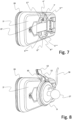
- the Figs. 7 and 8 show a further embodiment of the mounting arrangement with the housing 19 in a rear perspective view.
- the housing 19 is connected to the Base area 3' is formed.
- the housing 19 is designed to accommodate a mobile terminal.
- the base area 3' is formed on its outer side with two slot-shaped recesses 4" and 4" which are arranged parallel to the plane of the base area 3'.
- the base area 3' is additionally formed on its outer side with four depressions 5' to 5"', which are arranged within two further depression areas 6" and 6" arranged centrally within the base area 3'.
- the base area 3' is formed on its outer side with the contact means 7', which is an array of nine female contacts in the form of cylindrical recesses for receiving corresponding male contact pins.
- the housing 19 is formed with further contact means which serve for the electrical and/or electronic connection of a mobile terminal accommodated by the housing 19 with the contact means 7' on the outer side of the base area 3'.
- Fig. 8 shows the housing 18, which is mechanically and physically connected to the holding element 9, in a rear perspective view.
- the hook-shaped engagement means 10 engages positively in the recess 4" when the button 13 is released, with the lever arm 10 in its rest position.
- the hook-shaped engagement means 11 engages in the recess 4′′′, which in Fig. 8 is not shown due to perspective reasons.
- the contact means 7' are electrically connected to the contact means 15, which in Fig. 8 is not shown due to perspective reasons.
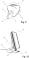
- Fig. 9 shows the suction cup holder 20 as a further element of the holder arrangement.
- the suction cup holder 20 comprises the suction cup 21 and the essentially cylindrical hollow body 22 with the circular opening 23 for receiving the ball head 17.
- the ball head 17 is releasably locked in the hollow body 22 by opening or closing the locking bracket 24.
- the suction cup holder 20 is attached to a windshield by pressing and turning the triangular disc 25 in the direction of arrow A, whereby the suction cup 21 is pressed in and air is expelled from it. A negative pressure is created between the interior of the suction cup 21 and the windshield.
- the suction cup holder 20 is released from the windshield by turning the triangular disc 25 in the direction of arrow A. direction of arrow B, whereby an opening (not shown) is released and air enters the suction cup 21 until pressure equalization with the atmosphere is achieved.
- the Fig. 10 to Fig. 15 show several different designs of storage or mounting devices, each designed as a wall, table or cabinet mount, each with one or more storage or mounting points.
- the storage or mounting points are each designed as a mounting element with at least two engagement means, each corresponding to the recesses 4 to 4′′′, and/or the depressions 5 to 5′′′ ⁇ and/or the depression areas 6 to 6′′′. Since the storage or mounting devices designed as a wall, table or cabinet mount of the Fig. 10 to Fig.
- Fig. 10 to Fig. 15 show embodiments of the bearing or holding devices in cooperation with one or more housings that essentially correspond to the housing 19. The bearing or holding devices of the Fig. 10 to Fig.
- Fig. 10 shows the single table mount 26 with the base 27 and the housing 19'. Furthermore, the single table mount 26 includes the data communication port 28 and the power supply cable 16'.
- Fig. 11 shows the single wall mount 29 with the housing 19'. Furthermore, the single wall mount 29 includes the data communication port 28' and the 16" power supply cable.
- Fig. 12 shows the multi-device table mount 30 with the base 27' and the housing 19' as well as further housings corresponding to the housing 19'. Furthermore, the multi-device table mount 30 includes the Data communication connectors 28" and 28′′′ and the power supply cable 16′′′.
- Fig. 10 shows the single table mount 26 with the base 27 and the housing 19'. Furthermore, the single table mount 26 includes the data communication port 28 and the power supply cable 16'.
- Fig. 11 shows the single wall mount 29 with the housing 19'. Furthermore, the single wall mount 29 includes the data communication port 28' and the 16" power supply cable.
- Fig. 12 shows the multi-device table mount 30 with the base 27'
- FIG. 13 shows the multi-device wall mount 31 and the housing 19' as well as other housings corresponding to the housing 19'. Furthermore, the multi-device wall mount 31 includes the data communication ports 28' and 28' and the 16' power supply cable.
- Fig. 14 shows the multi-device cabinet 32 and the housing 19', as well as another housing corresponding to the housing 19'. The multi-device cabinet 32 also includes the 16" power supply cable.
- the Figs. 15 and 16 show the adapter element 1' and the support element 9'.
- the adapter element 1' and the support element 9' are slightly modified versions of the adapter element 1 according to Fig. 1 and the support element 9 according to Fig. 3 .
- the adapter element 1' has, in contrast to the adapter element 1 according to the Fig. 1 no recesses 5, 5', 5" and 5′′′.
- the adapter element 1' is formed with four magnetic means 33a, 33a', 33a" and 33a′′′, the position of which within the depression areas 6" and 6′′′ in Fig. 15 is shown schematically.
- the polarity of the magnetic means 33a - 33a′′′ is shown in Figure 15
- the adapter element 1' is designed according to the adapter element 1.
- the mounting element 9' is, in contrast to the mounting element 9, designed according to the Fig. 3 formed with four magnetic means 33b, 33b', 33b" and 33b′′′, the position of which within the engagement means 14" and 14′′′ in Fig. 16 is shown schematically.
- the polarity of the magnetic means 33b - 33b′′′ is shown in Figure 16 drawn in.
- the holding element 9' is designed correspondingly to the holding element 9.
- Each of the magnetic means 33a' - 33a′′′ of the adapter element 1' is assigned one of the magnetic means 33b - 33b′′′ of the holding element 9' with respect to its polarity and positioning.
- the mutually assigned magnetic pairs 33a/33b, 33a'/33b', 33a"/33b" and 33a′′′/33b′′′ provide a magnetic force connection between the adapter element 1' and the holding element 9'.
- the magnetic means 33 and 33' on the one hand and the magnetic means 33" and 33′′′ on the other hand of the adapter element 1' are designed with a different polarity.
- the magnetic means 33b and 33b' on the one hand and the magnetic means 33b" and 33b′′′ on the other hand of the holding element 9' are also designed with a different polarity.
- the Fig. 17 shows the 19" housing.
- the 19" housing is corresponding to the 19" housing of the Figures 7 and 8 and is designed with two slot-shaped recesses, of which Fig. 17 Due to perspective reasons, only the recess 4" is visible.
- the housing is mechanically and physically connected to the mounting element 9".
- the hook-shaped engagement means 10' of the mounting element 9" engages in the recess 4"
- On the opposite long side of the housing 19" engages - which due to perspective reasons Fig. 17 not visible - a corresponding further hook-shaped engagement means of the holding element 9" into a corresponding slot-shaped recess in the housing 19".
- the engagement of the hook-shaped engagement means 10' in the recess 4"" can be released by applying pressure to the button 13'.
- the holding element 9" is on its - on the outside of the base surface of the housing 19" and in Fig. 17 not recognizable - top side otherwise corresponding to the mounting element 9 according to Fig. 3
- the holding element 9" is formed with a pistol-like handle 34, which is aligned substantially perpendicularly to the base of the housing 19". This enables easy, coordinated handling of a mobile terminal inserted into the housing 19", similar to a "pistol".
- the display side of the mobile terminal is located within the viewing area 35 arranged on the upper side of the housing 19", allowing the user to easily inspect the display during handling.
- the pistol-like handle is further formed with a cover flap 36, under which an additional battery is inserted into the handle 34.
- the additional battery serves to extend the operating time of a mobile terminal inserted into the housing 19", wherein it is connected via the contact means 15 of the Support element 9 according to Fig. 3 appropriate contact means is connected to the 19" housing.
Landscapes
- Engineering & Computer Science (AREA)
- Theoretical Computer Science (AREA)
- Signal Processing (AREA)
- Computer Hardware Design (AREA)
- Human Computer Interaction (AREA)
- Physics & Mathematics (AREA)
- General Engineering & Computer Science (AREA)
- General Physics & Mathematics (AREA)
- Computer Networks & Wireless Communication (AREA)
- Mechanical Engineering (AREA)
- Telephone Set Structure (AREA)
- Fittings On The Vehicle Exterior For Carrying Loads, And Devices For Holding Or Mounting Articles (AREA)
Description
- Die Erfindung betrifft eine Halterungsanordnung für mobile Endgeräte.
- Mobile Endgeräte sind tragbare elektronische Geräte mit mobiler Stromversorgung, wie etwa Mobiltelefone, Smartphones, Handhelds, PDAs, MDEs, Pocket Computer oder Tabletcomputer. Derartige Endgeräte sind zur mobilen Verwendung außerhalb eines ständigen stationären Stellorts oder -platzes geeignet und gedacht, wie etwa dem Telefonieren oder der Navigation beim Gehen oder Fahren oder dem Fotografieren oder der Datenerfassung oder -eingabe an einem belieben Einsatzort. Hierbei ist häufig eine freihändige Benutzung des mobilen Endgerätes erforderlich oder wünschenswert - etwa zur Navigation oder zum Telefonieren während des Fahrens mit einem Fahrzeug. Gleichzeitig erfordern solche Endgeräte beim mobilen Einsatz regelmäßig das Wiederaufladen ihrer mobilen Stromversorgung, in der Regel ist dies ein Akkumulator.
- Im Stand der Technik generell bekannt sind Einrichtungen zur Halterung eines mobilen Endgeräts in einem Fahrzeug, wie beispielsweise Saugnapf-Halterungen zur Befestigung eines Smartphones an der Innenseite der Windschutzscheibe eines Automobils. In der Regel über eine Kabelverbindung zum Zigarettenanzünder oder einen proprietären Anschluss zur Bordelektrik oder -elektronik ist hierbei gleichzeitig die Stromversorgung des Smartphones entweder zum Betrieb oder - soweit erforderlich - zum gleichzeitigen Wiederaufladung des Akkumulators gewährleistet. Ferner bekannt sind im Stand der Technik generell Andockstationen (Dockingstation, Cradle) zur Halterung oder Lagerung des mobilen Endgerätes an einem regelmäßigen stationären Aufenthaltsort, welche in der Regel eine physische Aufnahme- oder Lagerungseinrichtung sowie eine Einrichtung zur Energieversorgung umfassen. Nachteilhaft ist bei derartigen Einrichtungen generell, dass sie nur für einen bestimmten Einsatzzweck gedacht und ausgestaltetet sind, nämlich entweder zur Installation in einem Kraftfahrzeug oder zur Nutzung an einem regelmäßigen stationären Aufenthaltsort, beispielsweise dem Schreibtisch. Ferner sind derartige Einrichtungen regelmäßig zur Nutzung mit einem bestimmten Gerätetyp ausgestaltet.
- Geräte mit unterschiedlichen Abmessungen oder einer anderen Stromversorgungsschnittstelle können nicht mit derselben Saugnapf-Halterung oder Andockstation benutzt werden. Aus demselben Grund macht die Anschaffung eines neuen Gerätes gleichzeitig auch die Neuanschaffung einer passenden Saugnapf-Halterung und/oder Andockstation erforderlich. Bei der gewerblichen Nutzung oder dem industriellen Produktiveinsatz von unternehmenseigenen mobilen Endgeräten, beispielsweise zur mobilen Datenerfassung durch Mitarbeiter, die bestimmungsgemäß nach Arbeitsschluss in den Betriebsräumen verbleiben, ist die Anschaffung unterschiedlicher Halterungs- und Lagerungseinrichtungen mit Stromversorgung jeweils für den mobilen Einsatz in Fahrzeugen, als auch zur Lagerung in den Betriebsräumen erforderlich. Bei der Nutzung unterschiedlicher mobiler Endgeräte erfordert dies die Anschaffung und Bereitstellung entsprechender unterschiedlicher Halterungs- und Lagerungseinrichtungen. Bei einem Gerätewechsel müssen entsprechende neue Halterungs- und Lagerungseinrichtungen angeschafft werden.
- Aus der
DE 20 2014 010 006 U1 ist eine Schutzhülle und Basisstation für elektronische Handgeräte bekannt. Die Schutzhülle und die Basisstation ermöglichen die Halterung, Lagerung und Wiederaufladung lediglich an einem bestimmten stationären Stellort oder -platz für das Gerät. Ferner ist beides zur Verwendung mit einem bestimmten Gerätetyp abgestimmt, wobei jeder Gerätetyp eine Anpassung und Neuherstellung sämtlicher Komponenten erforderlich macht. Der parallele Einsatz unterschiedlicher Gerätetypen sowie ein Gerätewechsel in einem Unternehmen machen jeweils die Parallel- oder Neuanschaffung jeweils sämtlicher, entsprechend an die unterschiedlichen Gerätetypen angepasster Komponenten erforderlich. - Aus der 20 2016 003 776 U1 ist ein Bedienterminal bekannt, welches ein als verschließbares Gehäuse mit einem Innenraum zur Aufnahme eines Tablet-PCs ausgestaltetes Bedienteil und eine mit dem Bedienteil über eine lösbare mechanisch -körperliche Verbindung verbindbare Dockingstation umfasst. In einer Ausführung ist das Gehäuse über die Dockingstation mit einer Stromquelle verbindbar ausgebildet, indem sowohl die mechanisch-körperliche Verbindung, als auch der Innenraum des Gehäuses Kontaktmittel zur Herstellung einer Verbindung mit einer Stromquelle aufweisen. Aufgrund dieser technischen Gestaltung ermöglicht die von der 20 2016 003 776 U1 offenbarte Konstruktion die Verwendung der Dockingstation mit unterschiedlichen Tablet-PC-Modellen, indem jeweils lediglich das Gehäuse an die jeweilige Raumform des gewünschten Tablet-PCs angepasst werden muss. Das von der 20 2016 003 776 U1 offenbarte Bedienterminal ermöglicht jedoch lediglich die Halterung, Lagerung und Wiederaufladung von Tablet-PCs an einem bestimmten stationären Stellort oder -platz mit einer Dockingstation. Ferner ist zur Verwendung mit der Dockingstation für jeden Gerätetyp zwingend die Konfektionierung eines entsprechenden Gehäuses erforderlich.
- Die
WO 2014/034998 A1 offenbart eine Rückenschale für Smartphones, welche auf ihrer Innenseite und Außenseite elektrische Kontaktmittel zur elektrischen Kontaktierung eines in die Rückenschale eingelegten Smartphones mit einem externen Ladegerät aufweist. - Die
US 2004/132343 A1 offenbart eine Halterung für mobile Endgeräte, in die eine Adapterschale einstellbar und herausnehmbar ist. - Der Erfindung liegt die Aufgabe zugrunde, ein konstruktiv einfach herstellbares und modular konfektionierbares System zur Halterung, Lagerung und Wiederaufladung von unterschiedlichen mobilen Endgeräten sowohl bei deren mobilen Nutzung, als auch an einem stationären Stellort oder -platz zu schaffen. Insbesondere soll eine universell für unterschiedliche mobile Endgeräte nutzbare Schnittstelle sowohl für deren physische Halterung und Lagerung, als auch ihre elektrische Wiederaufladung geschaffen werden.
- Die Aufgabe wird erfindungsgemäß durch eine Halterungsanordnung nach Anspruch 1 gelöst, vorteilhafte Ausführungen sind in den Unteransprüchen beschrieben.
- Den Kern der Erfindung bildet eine Halterungsanordnung für mobile Endgeräte, die entweder ein mit einer Grundfläche ausgebildetes Gehäuse mit einem Innenraum, der zur Aufnahme eines mobilen Endgerätes ausgebildet ist, oder ein mit einer Grundfläche ausgebildetes Adapterelement, das mit einem mobilen Gerät mechanisch-körperlich verbindbar ausgestaltet ist, umfasst, wobei die Grundfläche auf ihrer Innenseite und ihrer Außenseite mit elektrischen Kontaktmitteln ausgebildet ist, welche derart ausgestaltet und angeordnet sind, dass eine elektrische Verbindung zwischen einem an oder auf der Innenseite der Grundfläche anordenbaren mobilen Endgerät und den auf der Außenseite ausgebildeten Kontaktmitteln herstellbar ist und wobei die Grundfläche von der Außenseite abgewinkelte Randbereiche aufweist, auf denen mindestens zwei Vertiefungen ausgebildet sind, die jeweils zur körperlichen Aufnahme eines Eingriffsmittels ausgestaltet sind. Die Grundfläche ist eine Fläche des Gehäuses oder Adapterelements, an oder auf der das mobile Endgerät anordenbar ist. Die Innenseite bezeichnet diejenige Seite der Grundfläche, an die oder auf der das mobile Endgerät anordenbar ist. Die Außenseite bezeichnet die von der Innenseite abgewandte Seite der Grundfläche. Als Einsenkung oder Vertiefung ist jedwede Einsenkung, Vertiefung, Einbuchtung, Schlitz oder Nut zu verstehen, welche eine körperliche Aufnahme eines korrespondieren Eingriffsmittels ermöglicht. Die mindestens zwei Einsenkungen oder Vertiefungen sind hierbei jeweils derart ausgestaltet, dass sie unter Berücksichtigung der jeweiligen Masse und des beabsichtigten Einsatzzwecks (z.B. stationär oder mobil) eine hinreichend sichere körperliche Fixierung eines vom Gehäuse oder dem Adapterelement aufgenommenen mobilen Endgeräts über korrespondierende Eingriffsmittel ermöglichen. Dies ist im Sinne der Erfindung etwa zur Nutzung als Halter in einem Automobil beispielsweise auch dann gewährleistet, wenn die Grundfläche auf ihrer Außenseite eine einzelne Einsenkung aufweist, die in ihrem Randbereich wiederrum senkrecht zur Eingriffsachse - d.h. in diesem Fall im Wesentlichen parallel zur Grundfläche - zwei schlitzförmige Vertiefungen zur Aufnahme von Haken quer zur Eingriffsrichtung aufweist. Die Einsenkungen oder Vertiefungen sind auf der Außenseite der Grundfläche ausgebildet. Sie können als Einsenkung, Vertiefung, Einbuchtung, Schlitz oder Nut in der Ebene der Grundfläche selbst oder in einem Winkel zu dieser angeordnet sein. Die Erfindung besitzt den Vorteil, dass ein konstruktiv einfach herstellbares und modular konfektionierbares System zur Halterung, Lagerung und Wiederaufladung von unterschiedlichen mobilen Endgeräten sowohl bei deren mobilen Nutzung, als auch an einem stationären Stellort oder -platz geschaffen ist. Die Schnittstelle ermöglicht sowohl die physische Halterung und Lagerung, als auch die elektrische Wiederaufladung von mobilen Endgeräten und ist universell mit unterschiedlichen Gerätetypen verwendbar, indem jeweils entweder ein entsprechend angepasstes Gehäuse oder ein Adapterelement vorhanden ist. Bei der parallelen Nutzung unterschiedlicher mobiler Endgeräte oder einem Gerätewechsel ist jeweils nur die Bereitstellung entsprechender Gehäuse oder Adapterelemente erforderlich, während die Ausgestaltung sämtlicher anderer Komponenten inklusive der Eingriffsmittel gleichbleibt oder diese weiterverwendet werden können. Einen besonderen Vorteil weist die Halterungsanordnung erfindungsgemäß ferner insoweit auf, als die körperliche Halterungsschnittstelle auf Seiten des Gehäuses oder Adapterelements (welche wiederum der Aufnahme des mobilen Endgeräts dienen) lediglich Einsenkungen oder Vertiefungen vorsieht, welche jeweils zur körperlichen Aufnahme eines Eingriffsmittels ausgestaltet sind. Hierdurch ist im Falle der Erforderlichkeit einer sperrbaren körperlichen Verbindung, etwa bei der Halterung eines mobilen Endgeräts in einem Automobil, gewährleistet, dass sämtliche erforderlichen beweglichen Teile außerhalb des Gehäuses oder Adapterelements ausgeführt werden können. Die Ausführung des Gehäuses oder Adapterelements - das jeweils an das bestimmungsgemäß aufzunehmende mobile Endgerät angepasst sein muss - ist hierdurch konstruktiv so einfach wie möglich gehalten. Ferner ist der für das Gehäuse oder Adapterelement - also geräteseitig - funktional erforderliche Bauraum hierdurch so gering wie möglich gehalten, was den ständigen Verbleib des Gehäuses oder Adapterelements am mobilen Endgerät unter Beibehaltung seiner mobilen Handhabbarkeit trotz Schaffung der erfindungsgemäßen Funktionalität ermöglicht.
- In einer konstruktiv einfachen Ausführung des Adapterelements ist dieses mit mindestens zwei formelastisch biegbaren Haltearmen ausgebildet, welche derart ausgestaltet und angeordnet sind, dass eine mechanisch-körperliche Verbindung mit einem mobilen Endgerät herstellbar ist, indem die Haltearme dieses an zwei gegenüberliegenden Randseiten formschlüssig umgreifen, wobei das mobile Endgerät an oder auf der Innenseite der Grundfläche anordenbar ist.
- Zur konstruktiv einfachen Umsetzung einer modularen Halterung des Gehäuses oder des Adapterelements (und damit eines mobilen Endgerätes) umfasst die Halterungsanordnung ein Halterungselement, das mit mindestens zwei, jeweils mit Einsenkungen oder Vertiefungen auf der Außenseite der Grundfläche korrespondierenden Eingriffsmitteln ausgebildet ist, welche zur Herstellung einer lösbaren form- und/oder kraftschlüssigen Verbindung des Halterungselements mit der Außenseite der Grundfläche ausgestaltet sind. Das Halterungselement stellt das Gegenstück zu der Halterungsschnittstelle des Gehäuses oder Adapterelements dar und ist je nach beabsichtigtem Verwendungszweck ausgebildet (bspw. Befestigung in einem Fahrzeug oder Halterung oder Lagerung an einem stationären Ort).
- Zur gleichzeitigen Nutzung als Ladequelle ist das Halterungselement mit Kontaktmitteln ausgebildet, welche zu den auf der Außenseite der Grundfläche des Gehäuses oder des Adapterelements ausgebildeten Kontaktmitteln korrespondierend angeordnet sind und ferner mit einer Anschlusseinrichtung ausgebildet, welche zur Herstellung einer elektrischen Verbindung der Kontaktmittel mit einer Stromquelle ausgestaltet ist.
- Um je nach Schnittstellenausstattung eines mit der Halterungsanordnung verwendeten mobilen Endgeräts und ja nach gewünschtem Einsatzzweck etwaige zusätzlich erforderliche Kabelverbindungen entbehrlich zu machen, ist die Anschlusseinrichtung zusätzlich zur Herstellung einer Datenkommunikationsverbindung ausgestaltet.
- Eine einfaches Verbinden und Lösen des Gehäuses oder Adapterelements mit dem oder von dem Halterungselement ist gewährleistet, indem zwei Eingriffsmittel aufseiten des Halterungselements hakenförmig ausgestaltet und paarweise zusammenwirkend angeordnet sind, wobei ein Eingriffsmittel starr und das andere Eingriffsmittel zur Herstellung oder zur Lösung der Verbindung des Halterungselements mit der Grundfläche entweder formelastisch biegbar oder gegen eine Federkraft bewegbar ausgestaltet ist und wobei beide Eingriffsmittel bei Bestehen der Verbindung in die jeweils korrespondierenden Vertiefungen auf der Außenseite der Grundfläche eingreifen.
- Eine einfache manuelle Bedienung des Verbindens und Lösens des Gehäuses oder Adapterelements mit dem oder vom Halterungselement ist gewährleistet, indem das formelastisch verbiegbar oder gegen eine Federkraft bewegbar ausgestaltete Eingriffsmittel mit einem starr verbundenen Hebelarm und der Hebelarm mit einer Druckfläche ausgebildet ist. Die Druckfläche ist hierzu beispielsweise als mit einer Fingerkuppe bedienbare Taste ausgestaltet, welche über den mit ihr starr verbundenen Hebelarm das Eingriffsmittel bei Druckausübung entweder formelastisch verbiegt oder gegen die Federkraft bewegt, wodurch das Eingreifen oder Lösen des Eingriffsmittels in die oder aus der korrespondierenden Vertiefung erreicht ist.
- Zur Verbesserung der Handhabung der Halterungsanordnung sind mindestens zwei Einsenkungen oder Vertiefungen auf der Außenseite der Grundfläche und gleichzeitig mindestens zwei mit diesen korrespondierenden Eingriffsmittel des Halterungselements mit Magnetmitteln ausgebildet, wobei jedem Magnetmittel der Grundfläche in Bezug auf seine Polung und Positionierung jeweils ein Magnetmittel des Halterungselements zugeordnet ist und wobei mindestens zwei Magnetmittel der Grundfläche einerseits und mindestens zwei Magnetmittel des Halterungselements andererseits untereinander jeweils mit einer unterschiedlichen Polung ausgebildet sind. Durch die einander zugeordneten Magnetmittelpaare wird ein zusätzlicher Kraftschluss zwischen dem Gehäuse oder Adapterelement und dem Halterungselement bereitgestellt. Gleichzeitig ist aufgrund der jeweils unterschiedlichen Polung der mindestens zwei Magnetmittel der Grundfläche einerseits und der mindestens zwei Magnetmittel des Halterungselements andererseits sichergestellt, dass das Gehäuse oder Adapterelement und das Halterungselement nur in einer Position miteinander verbunden werden können, da sich die Magnetmittelpaare in einer möglichen falschen Position - bei einer symmetrischen Ausgestaltung beispielsweise gegeneinander um 180° verdreht - abstoßen, anstatt anzuziehen. Aufgrund der magnetischen Abstoßung erhält der Benutzer hierbei zudem relativ früh ein haptisches Feedback bei einer möglichen falschen Positionierung.
- Die Verwendung des Halterungselements als mobile Halterungslösung in einem Automobil ist konstruktiv einfach gewährleistet, indem das Halterungselement mit einer Saugnapf-Halterung ausgebildet ist. Mit dem Saugnapf wird das Halterungselement beispielsweise in herkömmlicher Weise an der Innenseite der Windschutzscheibe befestigt.
- Eine weitere Verbesserung der Handhabung ist gewährleistet, indem das Halterungselement auf der der Außenseite der Grundfläche abgewandten Seite mit einem pistolenartigen Griff ausgebildet ist, welcher senkrecht oder in einem Winkelbereich von 60° bis 120° gegenüber der Grundfläche ausgerichtet ist. Dies ermöglicht die einfache koordinative Handhabung eines in das Gehäuse oder das Adapterelement eingelegten mobilen Endgeräts entsprechend einer "Pistole". Die Displayseite des mobilen Endgeräts befindet sich hierbei auf der Oberseite der Gesamtkonstruktion - parallel zur Grundfläche des Gehäuses oder des Adapterelements -, wodurch der Benutzer das Display bei der Handhabung einfach per Aufsicht in Augenschein nehmen kann. Es besteht ferner die Möglichkeit, in den pistolenartigen Griff einen Zusatzakkumulator oder eine Zusatzbatterie zur Verlängerung der Betriebszeit eines in das Gehäuse oder das Adapterelement eingelegten und mit diesem verbundenen mobilen Endgeräts zu integrieren.
- Eine Erweiterung der modularen Einsatzmöglichkeiten der Halterungsanordnung ist auf konstruktiv einfache Weise erreicht, indem das Halterungselement mit einem Kugelkopf zur Herstellung einer lösbaren form- und/oder kraftschlüssigen Verbindung mit einem weiteren Element ausgebildet ist. Der Kugelkopf dient der form- und/oder kraftschlüssigen Befestigung an einem weiteren, externen Element, dies kann beispielsweise eine Andockstation, eine Saugnapf-Halterung oder ein Stativ sein, welches ein mit dem Kugelkopf korrespondierendes Befestigungsmittel aufweist, beispielsweise feststellbare Backen mit an die Form des Kugelkopfes angepasste Umgriffsflächen oder einen feststellbaren Kugelsitz.
- Eine konstruktiv einfach herstellbare Lagerungs- oder Halterungseinrichtung sowie gegebenenfalls auch Wiederaufladungseinrichtung für jeweils ein oder mehrere Gehäuse oder Adapterelemente (und damit mehrere mobile Endgeräte) wird in einer konstruktiv einfachen Ausgestaltung bereitgestellt, indem die Halterungsanordnung eine als Wand-, Tisch- oder Schrankhalterung ausgebildete, Lagerungs- oder Halterungseinrichtung mit ein oder mehreren Lagerungs- oder Halterungsstellen umfasst, und wobei jede Lagerungs- oder Halterungsstelle jeweils als Halterungselement in einer der vorstehend beschriebenen Ausführungen ausgebildet ist.
- Weitere die Erfindung verbessernde Maßnahmen werden nachstehend gemeinsam mit der Beschreibung bevorzugter Ausführungsbeispiele der Erfindung anhand der Figuren näher dargestellt. Es zeigen:
- Fig. 1
- eine perspektivische Darstellung eines Adapterelements;
- Fig. 2
- eine perspektivische Darstellung eines mobilen Endgeräts und mit ihm verbundenen Adapterelement nach
Fig. 1 , - Fig. 3
- eine perspektivische Darstellung eines Halterungselements;
- Fig. 4
- eine perspektivische Darstellung des Adapterelements nach
Fig. 1 und des Halterungselements nachFig. 3 ; - Fig. 5
- eine weitere perspektivische Darstellung des Adapterelements nach
Fig. 1 und des Halterungselements nachFig. 3 ; - Fig. 6
- eine perspektivische Darstellung des mobilen Endgeräts und mit ihm verbundenen Adapterelements nach
Fig. 1 sowie dem mit dem Adapterelement verbundenen Halterungselement nachFig. 3 ; - Fig. 7
- eine perspektivische Darstellung eines Gehäuses;
- Fig. 8
- eine perspektivische Darstellung des Gehäuses nach
Fig. 7 sowie des dem mit dem Gehäuse verbundenen Halterungselements nachFig. 3 ; - Fig. 9
- eine perspektivische Darstellung einer Saugnapfhalterung;
- Fig. 10
- eine perspektivische Darstellung des Gehäuses nach
Fig. 7 sowie einer mit dem Gehäuse verbundenen Einzeltischhalterung; - Fig. 11
- eine perspektivische Darstellung des Gehäuses nach
Fig. 7 sowie einer mit dem Gehäuse verbundenen Einzelwandhalterung; - Fig. 12
- eine perspektivische Darstellung mehrerer Gehäuse sowie einer mit den Gehäusen verbundenen Mehrgerätetischhalterung;
- Fig. 13
- eine perspektivische Darstellung mehrerer Gehäuse sowie einer mit den Gehäusen verbundenen Mehrgerätewandhalterung;
- Fig. 14
- eine perspektivische Darstellung mehrerer Gehäuse sowie eines mit den Gehäusen verbundenen Mehrgeräteschranks.
- Fig. 15
- eine perspektivische Darstellung eines weiteren Adapterelements;
- Fig. 16
- eine perspektivische Darstellung eines weiteren Halterungselements;
- Fig. 17
- eine perspektivische Darstellung eines weiteren Gehäuses.
- Die
Fig. 1 und Fig. 2 zeigen das Adapterelement 1, welches mit zwei formelastisch biegbaren Haltearmen 2 und 2' ausgebildet ist. Das Adapterelement 1 ist mit der Grundfläche 3 ausgebildet. Randseitig ist die Grundfläche 3 auf ihrer Außenseite mit zwei schlitzförmigen Vertiefungen 4 und 4' ausgebildet, welche parallel zur Ebene der Grundfläche 3 angeordnet sind. Ferner ist die Grundfläche 3 auf ihrer Außenseite zusätzlich mit vier Einsenkungen 5 bis 5‴ ausgebildet, welche innerhalb zweier weiterer, innerhalb der Grundfläche 3 zentral angeordneter Einsenkungsbereiche 6 und 6' angeordnet sind. Schließlich ist die Grundfläche 3 auf ihrer Außenseite mit den Kontaktmitteln 7 ausgebildet, welches ein Feld von neun weiblichen Kontakten in Form zylindrischer Vertiefungen zur Aufnahme korrespondierender männlicher Kontaktstifte ist. DieFig. 2 zeigt das Adapterelement 1, welches mit dem mobilen Endgerät 8 mechanisch-körperlich verbunden ist. Hierbei umgreifen die Haltearme 2 und 2' das mobile Endgerät 8 an zwei gegenüberliegenden Randseiten formschlüssig.Fig. 3 zeigt das Halterungselement 9. Das Halterungselement 9 ist mit zwei hakenförmigen Eingriffsmitteln 10 und 11 ausgebildet, welche mit den schlitzförmigen Vertiefungen 4 und 4' korrespondieren. Die beiden hakenförmigen Eingriffsmittel 10 und 11 des Halterungselements 9 sind paarweise zusammenwirkend angeordnet, um gegenläufig fixierend auf ein Werkstück zu wirken, in dessen korrespondierende Vertiefungen sie eingreifen. Das hakenförmige Eingriffsmittel 10 ist formelastisch biegbar ausgestaltet und mit dem Hebelarm 12 verbunden. Der Hebelarm 12 ist an seinem Ende als Druckfläche mit der Taste 13 ausgebildet. Das hakenförmige Eingriffsmittel 11 ist starr ausgebildet. Die Herstellung oder Lösung einer formschlüssigen Verbindung der hakenförmigen Eingriffsmittel 10 und 11mit den mit den schlitzförmigen Vertiefungen 4 und 4' erfolgt durch manuellen Druckausübung auf die Taste 13 - beispielsweise mit einer Fingerkuppe - wobei sich der Hebelarm 12 nach hinten verbiegt und das mit diesem verbundene hakenförmige Eingriffsmittel 10 seine Position nach oben verlagert und die mit ihm korrespondierende schlitzförmige Vertiefung 4 verlassen kann. Bei Entlastung der Taste 13 bewegt sich der Hebelarm 11 nach vorne in seine Ruhestellung zurück, wobei das mit ihm verbundene hakenförmige Eingriffsmittel 10 seine Position nach unten verlagert und in die schlitzförmige Vertiefung 4 eingreifen kann. Ferner ist das Halterungselement 9 zusätzlich mit den Eingriffsmitteln 14 und 14' ausgebildet, welche als Ausbuchtungen ausgestaltet sind und die mit den Einsenkungsbereichen 6 und 6' korrespondieren. Die Eingriffsrichtung der Eingriffsmittel 14 und 14' in die korrespondierenden Einsenkungsbereiche 6 und 6' definieren hierbei eine Eingriffsachse im Sinne der Erfindung. Gegenüber dieser Eingriffsachse sind die schlitzförmigen Vertiefungen 4 und 4' senkrecht angeordnet. Schließlich ist das Halterungselement 9 mit den Kontaktmitteln 15 ausgebildet, welche als Feld von vier männlichen Kontaktstiften ausgestaltet sind, die korrespondierend zu den Kontaktmitteln 7 angeordnet sind. Zudem ist das Halterungselement 9 mit der als Kabel 16 ausgebildeten Anschlusseinrichtung ausgebildet, welche zur Herstellung einer elektrischen Verbindung der Kontaktmittel 15 mit einer Stromquelle, beispielsweise einem Zigarettenanzünder in einem Kraftfahrzeug, ausgestaltet ist. Das Halterungselement 9 kann als Teil der Anschlusseinrichtung darüber hinaus weitere elektrische oder elektronische Komponenten, wie beispielweise eine Elektronik zur Regelung/oder Anpassung einer anliegenden Versorgungsspannung oder Stromstärke umfassen. Ferner kann das Kabel 16 zusätzlich zur Spannungsversorgung auch zur Herstellung einer Datenkommunikationsverbindung, beispielsweise mit der Bordelektronik eines Automobils, ausgestaltet sein. Hierbei können die Kontaktmittel 15 und/oder auch die Kontaktmittel 7 weitere Kontaktstifte oder weibliche Kontakte in Form zylindrischer Vertiefungen umfassen, um insgesamt die für die gewünschten elektrischen oder elektronischen Verbindungen erforderlichen Leitungen abzubilden.Fig. 4 . zeigt das Halterungselement 9 gemeinsam mit dem zu verbindenden Adapterelement 1. Das Halterungselement 9 ist auf seiner Rückseite - das heißt, der dem Adapterelement 1 abgewandten Seite - mit dem Kugelkopf 17 ausgebildet. Der Kugelkopf 17 dient der körperlichen Verbindung mit weiteren Elementen, beispielsweise einer Saugnapf-Halterung zur lösbaren Befestigung des Halterungselements 9 an der Innenseite einer Windschutzscheibe. Anstatt mit dem Kugelkopf 17 kann das Halterungselement 9 bspw. auch direkt mit einem Befestigungsmittel wie beispielsweise einer Saugnapf-Halterung, ausgebildet sein. Auf der Innenseite seiner Grundfläche 3 ist das Adapterelement 1 mit den Kontaktmitteln 18 ausgebildet, die als Feld von mehreren männlichen Kontaktstiften ausgestaltet sind. Die Kontaktmittel 18 dienen der elektrischen und/oder elektronischen Verbindung des mobilen Endgeräts 8 mit den Kontaktmitteln 7 auf der Außenseite der Grundfläche 3.Fig. 5 zeigt die körperliche Verbindung des Halterungselements 9 mit dem Adapterelement 1 in einer rückwärtigen perspektivischen Ansicht. Das hakenförmige Eingriffsmittel 10 greift bei Entlastung der Taste 13, bei sich der Hebelarm 12 in seiner Ruhestellung befindet, formschlüssig in die Vertiefung 4 ein. Gleichzeitig greift das hakenförmige Eingriffsmittel 11 in die Vertiefung 4' ein, was inFig. 5 perspektivisch bedingt nicht dargestellt ist.Fig. 6 zeigt die körperliche Verbindung des Halterungselements 9 mit dem Adapterelement 1 und des Adapterelements 1 mit dem mobilen Endgerät 8 in einer rückwärtigen perspektivischen Ansicht. die Haltearme 2 und 2' umgreifen das mobile Endgerät 8 an zwei gegenüberliegenden Randseiten formschlüssig. - Die
Fig. 7 und 8 zeigen eine weitere Ausführungsform der Halterungsanordnung mit dem Gehäuse 19 in einer rückwärtigen perspektivischen Ansicht. Das Gehäuse 19 ist mit der Grundfläche 3' ausgebildet. Das Gehäuse 19 ist zur Aufnahme eines mobilen Endgerätes ausgebildet. Randseitig ist die Grundfläche 3' auf ihrer Außenseite mit zwei schlitzförmigen Vertiefungen 4" und 4‴ ausgebildet, welche parallel zur Ebene der Grundfläche 3' angeordnet sind. Ferner ist die Grundfläche 3' auf ihrer Außenseite zusätzlich mit vier Einsenkungen 5ʺʺ bis 5‴ʺʺ ausgebildet, welche innerhalb zweier weiterer, innerhalb der Grundfläche 3' zentral angeordneter Einsenkungsbereiche 6" und 6‴ angeordnet sind. Schließlich ist die Grundfläche 3' auf ihrer Außenseite mit den Kontaktmitteln 7' ausgebildet, welches ein Feld von neun weiblichen Kontakten in Form zylindrischer Vertiefungen zur Aufnahme korrespondierender männlicher Kontaktstifte ist. Auf der Innenseite seiner Grundfläche 3' ist das Gehäuse 19 mit weiteren Kontaktmitteln ausgebildet, die der elektrischen und/oder elektronischen Verbindung eines vom Gehäuse 19 aufgenommenen mobilen Endgeräts mit den Kontaktmitteln 7' auf der Außenseite der Grundfläche 3' dienen. DieFig. 8 zeigt das Gehäuse 18, welches mit dem Halterungselement 9 mechanisch-körperlich verbunden ist, in einer rückwärtigen perspektivischen Ansicht. Das hakenförmige Eingriffsmittel 10 greift bei Entlastung der Taste 13, bei sich der Hebelarm 10 in seiner Ruhestellung befindet, formschlüssig in die Vertiefung 4" ein. Gleichzeitig greift das hakenförmige Eingriffsmittel 11 in die Vertiefung 4‴ ein, was inFig. 8 perspektivisch bedingt nicht dargestellt ist. Gleichzeitig sind hierbei die Kontaktmittel 7' mit den Kontaktmitteln 15 elektrisch verbunden, was inFig. 8 perspektivisch bedingt nicht dargestellt ist. -
Fig. 9 zeigt als weiteres Element der Halterungsanordnung die Saugnapf-Halterung 20. Die Saugnapf-Halterung 20 umfasst den Saugnapf 21 und den im Wesentlichen zylindrischen Hohlkörper 22 mit der kreisrunden Öffnung 23 zur Aufnahme des Kugelkopfes 17. Die lösbare Arretierung des Kugelkopfes 17 im Hohlkörper 22 erfolgt durch Öffnen oder Schließen des Arretierungsbügels 24. Die Befestigung der Saugnapf-Halterung 20 an einer Windschutzscheibe erfolgt durch Andrücken und Drehen der Dreiecksscheibe 25 entsprechend der Pfeilrichtung A, wodurch der Saugnapf 21 eingedrückt und Luft aus diesem verdrängt wird. Es entsteht ein Unterdruck zwischen dem Innenraum des Saugnapfs 21 und der Windschutzscheibe. Das Lösen der Saugnapf-Halterung 20 von der Windschutzscheibe erfolgt durch Drehen der Dreiecksscheibe 25 entsprechend der Pfeilrichtung B, wodurch eine Öffnung (nicht dargestellt) freigegeben wird und Luft in den Saugnapf 21 eindringt, bis ein Druckausgleich mit der Atmosphäre hergestellt ist. - Die
Fig. 10 bis Fig. 15 zeigen mehrere verschiedene Ausführungen von jeweils als Wand-, Tisch- oder Schrankhalterung ausgebildeten Lagerungs- oder Halterungseinrichtungen mit jeweils ein oder mehreren Lagerungs- oder Halterungsstellen. Die Lagerungs- oder Halterungsstellen sind jeweils als ein Halterungselement mit mindestens zwei, jeweils mit den Vertiefungen 4 bis 4‴, und/oder den Einsenkungen 5 bis 5‴ʺʺ und/oder den Einsenkungsbereichen 6 bis 6‴ korrespondierenden Eingriffsmitteln ausgebildet. Da die als Wand-, Tisch- oder Schrankhalterung ausgebildeten Lagerungs- oder Halterungseinrichtungen derFig. 10 bis Fig. 15 jeweils als stationäre Lagerungs- oder Halterungsorte dienen, reichen zur Herstellung einer hinreichend stabilen Verbindung mit den Gehäusen oder Adapterelementen jeweils beispielsweise auch einfache, nicht sperrende formschlüssige Eingriffsmittel entsprechend den Eingriffsmitteln 14 und 14' und/oder mit den Einsenkungen 5 bis 5‴ʺʺ korrespondierende Eingriffsmittel aus. Ferner sind die Lagerungs- oder Halterungsstellen jeweils mit zu den Kontaktmitteln 7 und 7' korrespondierenden Kontaktmitteln - entsprechend den Kontaktmitteln 15 - ausgebildet, und mit Anschlusseinrichtungen ausgebildet, welche zur Herstellung einer elektrischen Verbindung mit einer Stromquelle sowie einer Datenkommunikationsverbindung ausgestaltet sind. DieFig. 10 bis Fig. 15 zeigen hierbei jeweils Ausführungen der Lagerungs- oder Halterungseinrichtungen im Zusammenwirken mit einem oder mehreren dem Gehäuse 19 im Wesentlichen entsprechenden Gehäusen. Die Lagerungs- oder Halterungseinrichtungen derFig. 10 bis Fig. 15 sind hierbei bei jedoch gleichfalls zum Zusammenwirken mit einem oder mehreren dem Adapterelement 1 entsprechenden Adapterelementen geeignet.Fig. 10 zeigt die Einzeltischhalterung 26 mit dem Standfuß 27 und dem Gehäuse 19'. Ferner umfasst die Einzeltischhalterung 26 den Datenkommunikationsanschluss 28 und das der Spannungsversorgung dienende Kabel 16'.Fig. 11 zeigt die Einzelwandhalterung 29 mit dem Gehäuse 19'. Ferner umfasst die Einzelwandhalterung 29 den Datenkommunikationsanschluss 28' und das der Spannungsversorgung dienende Kabel 16".Fig. 12 zeigt die Mehrgerätetischhalterung 30 mit dem Standfuß 27' und dem Gehäuse 19' sowie weiteren, dem Gehäuse 19' entsprechenden Gehäusen. Ferner umfasst die Mehrgerätetischhalterung 30 die Datenkommunikationsanschlüsse 28" und 28‴ und das der Spannungsversorgung dienende Kabel 16‴.Fig. 13 zeigt die Mehrgerätewandhalterung 31 und dem Gehäuse 19' sowie weiteren, dem Gehäuse 19' entsprechenden Gehäusen. Ferner umfasst die Mehrgerätewandhalterung 31 die Datenkommunikationsanschlüsse 28ʺʺ und 28‴ʺ und das der Spannungsversorgung dienende Kabel 16ʺʺ.Fig. 14 zeigt den Mehrgeräteschrank 32 und das Gehäuse 19' sowie weiteren, dem Gehäuse 19' entsprechende Gehäuse. Der Mehrgeräteschrank 32 umfasst ferner das der Spannungsversorgung dienende Kabel 16‴ʺ. - Die
Fig. 15 und 16 zeigen das Adapterelement 1' und das Halterungselement 9'. Das Adapterelement 1' und das Halterungselement 9' sind leicht abgewandelte Ausführungen des Adapterelements 1 gemäßFig. 1 und des Halterungselements 9 gemäßFig. 3 . Das Adapterelement 1' weist im Gegensatz zum Adapterelement 1 gemäß derFig. 1 keine Einsenkungen 5, 5', 5" und 5‴ auf. Im Gegensatz zum Adapterelement 1 gemäß derFig. 1 ist das Adapterelement 1' mit vier Magnetmitteln 33a, 33a', 33a" und 33a‴ ausgebildet, deren Position innerhalb der Einsenkungsbereiche 6" und 6‴ inFig. 15 schematisch eingezeichnet ist. Ferner ist jeweils die Polung der Magnetmittel 33a - 33a‴ inFigur 15 eingezeichnet. Im Übrigen ist das Adapterelement 1' entsprechend dem Adapterelement 1 ausgeführt. Das Halterungselement 9' ist im Gegensatz zum Halterungselement 9 gemäß derFig. 3 mit vier Magnetmitteln 33b, 33b', 33b" und 33b‴ ausgebildet, deren Position innerhalb der Eingriffsmittel 14" und 14‴ inFig. 16 schematisch eingezeichnet ist. Ferner ist jeweils die Polung der Magnetmittel 33b - 33b‴ inFigur 16 eingezeichnet. Im Übrigen ist das Halterungselement 9 'entsprechend dem Halterungselement 9 ausgeführt. Jedem der Magnetmittel 33a' - 33a‴ des Adapterelements 1' ist in Bezug auf seine Polung und Positionierung jeweils eines der Magnetmittel 33b - 33b‴ des Halterungselements 9' zugeordnet. Durch die einander zugeordneten Magnetmittelpaare 33a/33b, 33a'/33b', 33a"/33b" und 33a‴/33b‴wird ein magnetischer Kraftschluss zwischen dem Adapterelement 1' und dem Halterungselement 9' bereitgestellt. Hierbei sind die Magnetmittel 33 und 33' einerseits und die Magnetmittel 33" und 33‴ anderseits des Adapterelements 1' mit einer unterschiedlichen Polung ausgebildet. Gleichzeitig sind auch die Magnetmittel 33b und 33b' einerseits und die Magnetmittel 33b" und 33b‴ andererseits des Halterungselements 9' mit einer unterschiedlichen Polung ausgeführt. - Hierdurch ist sichergestellt, dass das Adapterelement 1' und das Halterungselement 9' nur in einer Position miteinander verbunden werden können, da sich die Magnetmittelpaare in einer möglichen falschen Position - gegeneinander um 180° verdreht - abstoßen, anstatt gegenseitig anzuziehen. Aufgrund der magnetischen Abstoßung in der gegeneinander um 180° verdrehten Position erhält der Benutzer hierbei zudem relativ früh ein haptisches Feedback beim Versuch einer falschen Positionierung.
- Die
Fig. 17 zeigt das Gehäuse 19". Das Gehäuse 19" ist entsprechend dem Gehäuse 19 derFiguren 7 und 8 ausgeführt und unter anderem mit zwei schlitzförmigen Vertiefungen ausgeführt, von denen inFig. 17 perspektivisch bedingt lediglich die Vertiefung 4ʺʺ erkennbar ist. Das Gehäuse ist mechanisch-körperlich mit dem Halterungselement 9" verbunden. Hierbei greift das hakenförmige Eingriffsmittel 10' des Halterungselements 9" in die Vertiefung 4ʺʺ ein. Auf der gegenüberliegenden Längsseite des Gehäuses 19" greift - was perspektivisch bedingt inFig. 17 nicht erkennbar ist - ein entsprechendes weiteres hakenförmiges Eingriffsmittel des Halterungselements 9" in eine korrespondierende schlitzförmige Vertiefung im Gehäuse 19" ein. Der Eingriff des das hakenförmigen Eingriffsmittels 10' in die Vertiefung 4"" lässt sich durch Belastung der Taste 13' lösen. Das Halterungselement 9" ist auf seiner - an der Außenseite der Grundfläche des Gehäuses 19" anliegenden und inFig. 17 nicht erkennbaren - Oberseite im Übrigen entsprechend dem Halterungselement 9 gemäßFig. 3 ausgeführt. Auf seiner der Außenseite der Grundfläche des Gehäuses 19" abgewandten Seite ist das Halterungselement 9" mit einem pistolenartigen Griff 34 ausgebildet, der im Wesentlichen senkrecht gegenüber der Grundfläche des Gehäuses 19" ausgerichtet ist. Dies ermöglicht die einfache koordinative Handhabung eines in das Gehäuse 19" eingelegten mobilen Endgeräts entsprechend einer "Pistole". Die Displayseite des mobilen Endgeräts befindet sich hierbei innerhalb des auf der Oberseite des Gehäuses 19" angeordneten Sichtbereichs 35, wodurch der Benutzer das Display bei der Handhabung einfach per Aufsicht in Augenschein nehmen kann. Der pistolenartige Griff ist ferner mit einer Abdeckklappe 36 ausgebildet, unter welcher einen Zusatzakkumulator in den Griff 34 eingesetzt ist. Der Zusatzakkumulator dient der Verlängerung der Betriebszeit eines in das Gehäuse 19" eingelegten mobilen Endgeräts, wobei er über den Kontaktmitteln 15 des Halterungselements 9 gemäßFig. 3 entsprechende Kontaktmittel mit dem Gehäuse 19" verbunden ist. -
- 1, 1'
- Adapterelement
- 2, 2'
- Haltearme
- 3
- Grundfläche
- 4, 4', 4", 4‴, 4ʺʺ
- Vertiefungen
- 5, 5, 5", 5‴, 5 5‴ʺ, 5‴‴, 5‴ʺʺ
- Einsenkungen
- 6, 6', 6", 6‴
- Einsenkungsbereiche
- 7, 7'
- Kontaktmittel Grundfläche Außenseite
- 8
- Mobiles Endgerät
- 9, 9', 9"
- Halterungselement
- 10, 10', 11, 14, 14', 14'', 14‴
- Eingriffsmittel
- 12
- Hebelarm
- 13, 13'
- Taste
- 15
- Kontaktmittel Halterungselement
- 16, 16', 16", 16"', 16ʺʺ
- Kabel
- 17
- Kugelkopf
- 18
- Kontaktmittel Grundfläche Innenseite
- 19, 19', 19"
- Gehäuse
- 20
- Saugnapf-Halterung
- 21
- Saugnapf
- 22
- Hohlkörper
- 23
- Öffnung
- 24
- Arretierungsbügel
- 25
- Dreiecksscheibe
- 26
- Einzeltischhalterung
- 27, 27'
- Standfuß
- 28, 28', 28", 28"', 28"", 28‴ʺ
- Datenkommunikationsanschluss
- 29
- Einzelwandhalterung
- 30
- Mehrgerätetischhalterung
- 31
- Mehrgerätewandhalterung
- 32
- Mehrgeräteschrank
- 33a, 33a', 33a'', 33a‴, 33b, 33b', 33b", 33b‴
- Magnetmittel
- 34
- Griff
- 35
- Sichtbereich
- 36
- Abdeckklappe
Claims (12)
- Halterungsanordnung für mobile Endgeräte, umfassend entweder ein mit einer Grundfläche ausgebildetes Gehäuse mit einem Innenraum, der zur Aufnahme eines mobilen Endgerätes ausgebildet ist, oder ein mit einer Grundfläche ausgebildetes Adapterelement, das mit einem mobilen Gerät mechanisch-körperlich verbindbar ausgestaltet ist, wobei die Grundfläche (3) auf ihrer Innenseite und ihrer Außenseite mit elektrischen Kontaktmitteln (7, 7', 18) ausgebildet ist, welche derart ausgestaltet und angeordnet sind, dass eine elektrische Verbindung zwischen einem an oder auf der Innenseite der Grundfläche (3) anordenbaren mobilen Endgerät und den auf der Außenseite ausgebildeten Kontaktmitteln (7, 7") herstellbar ist, dadurch gekennzeichnet, dass die Grundfläche (3) von der Außenseite abgewinkelte Randbereiche aufweist, auf denen mindestens zwei Vertiefungen (4, 4', 4", 4‴, 4ʺʺ) ausgebildet sind, die jeweils zur körperlichen Aufnahme eines Eingriffsmittels (10, 10', 11) parallel zur Ebene der Grundfläche (3) ausgestaltet sind, wobei die Vertiefungen (4, 4', 4", 4‴, 4ʺʺ) jeweils über eine schlitzförmige Öffnung zugänglich sind, die in einer Ebene senkrecht zur Grundfläche angeordnet ist.
- Halterungsanordnung nach Anspruch 1 mit einem Adapterelement, dadurch gekennzeichnet, dass das Adapterelement (1, 1') mit mindestens zwei formelastisch biegbaren Haltearmen (2, 2') ausgebildet ist, welche derart ausgestaltet und angeordnet sind, dass eine mechanisch-körperliche Verbindung mit einem mobilen Endgerät herstellbar ist, indem die Haltearme (2, 2') dieses an zwei gegenüberliegenden Randseiten formschlüssig umgreifen, wobei das mobile Endgerät an oder auf der Innenseite der Grundfläche (3) anordenbar ist.
- Halterungsanordnung nach Anspruch 1 oder 2, dadurch gekennzeichnet, dass die Halterungsanordnung ein Halterungselement (9, 9', 9") umfasst, das mit mindestens zwei, jeweils mit den Vertiefungen (4, 4', 4", 4"', 4ʺʺ) auf der Außenseite der Grundfläche (3) korrespondierenden Eingriffsmitteln (10, 10', 11) ausgebildet ist, welche zur Herstellung einer lösbaren form- und/oder kraftschlüssigen Verbindung des Halterungselements (9, 9', 9") mit der Außenseite der Grundfläche (3) ausgestaltet sind.
- Halterungsanordnung nach Anspruch 3, dadurch gekennzeichnet, dass das Halterungselement (9, 9', 9") mit Kontaktmitteln (15) ausgebildet ist, welche zu den auf der Außenseite der Grundfläche (3) des Gehäuses (19, 19', 19") oder des Adapterelements (1, 1') ausgebildeten Kontaktmitteln (7, 7") korrespondierend angeordnet sind und das Halterungselement (9, 9', 9") ferner mit einer Anschlusseinrichtung ausgebildet ist, welche zur Herstellung einer elektrischen Verbindung der Kontaktmittel (15) mit einer Stromquelle ausgestaltet ist.
- Halterungsanordnung nach Anspruch 4, dadurch gekennzeichnet, dass die Anschlusseinrichtung zusätzlich zur Herstellung einer Datenkommunikationsverbindung ausgestaltet ist.
- Halterungsanordnung nach einem der Ansprüche 3 bis 5, dadurch gekennzeichnet, dass zwei Eingriffsmittel (10, 10', 11, 14, 14', 14", 14‴) hakenförmig ausgestaltet und paarweise zusammenwirkend angeordnet sind, wobei ein Eingriffsmittel (10, 10', 11, 14, 14', 14", 14‴) starr und das andere Eingriffsmittel (10, 10', 11, 14, 14', 14", 14‴) zur Herstellung oder zur Lösung der Verbindung des Halterungselements (9, 9', 9") mit der Grundfläche (3) entweder formelastisch biegbar oder gegen eine Federkraft bewegbar ausgestaltet ist und wobei beide Eingriffsmittel (10, 10', 11, 14, 14', 14", 14‴) bei Bestehen der Verbindung in die jeweils korrespondierenden Vertiefungen (4, 4', 4", 4‴, 4ʺʺ) auf der Außenseite der Grundfläche (3) eingreifen.
- Halterungsanordnung nach Anspruch 6, dadurch gekennzeichnet, dass das formelastisch verbiegbar oder gegen eine Federkraft bewegbar ausgestaltete Eingriffsmittel (10, 10', 11, 14, 14', 14", 14‴) mit einem starr verbundenen Hebelarm (12) und der Hebelarm (12) mit einer Druckfläche ausgebildet ist.
- Halterungsanordnung nach einem der Ansprüche 3 bis 7, dadurch gekennzeichnet, dass mindestens zwei Einsenkungen (5, 5', 5", 5‴, 5ʺʺ, 5‴ʺ, 5‴‴, 5‴ʺʺ, 6, 6', 6", 6‴) oder Vertiefungen (4, 4', 4", 4‴, 4ʺʺ) auf der Außenseite der Grundfläche (3) und gleichzeitig mindestens zwei mit diesen korrespondierenden Eingriffsmittel (10, 10', 11, 14, 14', 14", 14‴) des Halterungselements (9, 9', 9") mit Magnetmitteln (33a, 33a', 33a", 33a‴, 33b, 33b', 33b", 33b‴) ausgebildet sind, wobei jedem Magnetmittel (33a, 33a', 33a", 33a‴, 33b, 33b', 33b", 33b‴) der Grundfläche (3) in Bezug auf seine Polung und Positionierung jeweils ein Magnetmittel (33a, 33a', 33a", 33a‴, 33b, 33b', 33b", 33b‴) des Halterungselements (9, 9', 9") zugeordnet ist und wobei mindestens zwei Magnetmittel (33a, 33a', 33a", 33a‴, 33b, 33b', 33b", 33b‴) der Grundfläche (3) einerseits und mindestens zwei Magnetmittel (33a, 33a', 33a", 33a‴, 33b, 33b', 33b", 33b‴) des Halterungselements (9, 9', 9") andererseits untereinander jeweils mit einer unterschiedlichen Polung ausgebildet sind.
- Halterungsanordnung nach einem der Ansprüche 3 bis 8, dadurch gekennzeichnet, dass das Halterungselement (9, 9', 9") mit einer Saugnapf-Halterung (20) ausgebildet ist.
- Halterungsanordnung nach einem der Ansprüche 3 bis 8, dadurch gekennzeichnet, dass das Halterungselement auf der der Außenseite der Grundfläche (3) abgewandten Seite mit einem pistolenartigen Griff (34) ausgebildet ist, welcher senkrecht oder in einem Winkelbereich von 60° bis 120° gegenüber der Grundfläche (3) ausgerichtet ist.
- Halterungsanordnung nach einem der Ansprüche 3 bis 8, dadurch gekennzeichnet, dass das Halterungselement (9, 9', 9") mit einem Kugelkopf (17) zur Herstellung einer lösbaren form- und/oder kraftschlüssigen Verbindung mit einem weiteren Element ausgebildet ist.
- Halterungsanordnung nach einem der Ansprüche 3 bis 8, dadurch gekennzeichnet, dass die Halterungsanordnung eine als Wand-, Tisch- oder Schrankhalterung ausgebildete, Lagerungs- oder Halterungseinrichtung mit ein oder mehreren Lagerungs- oder Halterungsstellen umfasst, und wobei jede Lagerungs- oder Halterungsstelle jeweils als Halterungselement (9, 9', 9") nach einem der Ansprüche 3 bis 8 ausgebildet ist.
Applications Claiming Priority (2)
| Application Number | Priority Date | Filing Date | Title |
|---|---|---|---|
| DE202017003503.0U DE202017003503U1 (de) | 2017-07-04 | 2017-07-04 | Halterungsanordnung für mobile Endgeräte |
| PCT/DE2018/000201 WO2019007450A1 (de) | 2017-07-04 | 2018-07-03 | Halterungsanordnung für mobile endgeräte |
Publications (2)
| Publication Number | Publication Date |
|---|---|
| EP3649770A1 EP3649770A1 (de) | 2020-05-13 |
| EP3649770B1 true EP3649770B1 (de) | 2025-03-12 |
Family
ID=59814725
Family Applications (1)
| Application Number | Title | Priority Date | Filing Date |
|---|---|---|---|
| EP18759542.6A Active EP3649770B1 (de) | 2017-07-04 | 2018-07-03 | Halterungsanordnung für mobile endgeräte |
Country Status (6)
| Country | Link |
|---|---|
| US (1) | US11375055B2 (de) |
| EP (1) | EP3649770B1 (de) |
| DE (2) | DE202017003503U1 (de) |
| DK (1) | DK3649770T3 (de) |
| ES (1) | ES3032645T3 (de) |
| WO (1) | WO2019007450A1 (de) |
Families Citing this family (5)
| Publication number | Priority date | Publication date | Assignee | Title |
|---|---|---|---|---|
| DE202018001372U1 (de) | 2018-03-15 | 2019-06-18 | Dmg Mori Aktiengesellschaft | Halterung für einen Tabletcomputer und System mit solchen Halterungen |
| TWI750754B (zh) | 2019-07-31 | 2021-12-21 | 美商巔峰設計公司 | 安裝系統 |
| DE102021208755A1 (de) | 2021-08-11 | 2023-02-16 | Robert Bosch Gesellschaft mit beschränkter Haftung | Trägervorrichtung, Aufnahmeeinheit, Trägersystem und Verfahren zum Herstellen eines Trägersystems |
| TWI800263B (zh) * | 2022-02-16 | 2023-04-21 | 寶德科技股份有限公司 | 可結合可攜式電子裝置之操控組件 |
| US20260075726A1 (en) * | 2024-09-11 | 2026-03-12 | Xue-feng Chen | Router power supply support rack |
Family Cites Families (16)
| Publication number | Priority date | Publication date | Assignee | Title |
|---|---|---|---|---|
| DE19955095A1 (de) * | 1999-11-16 | 2001-05-23 | Siemens Ag | Handyhalterung in Kraftfahrzeugen |
| DE10164799B4 (de) * | 2001-03-21 | 2006-03-30 | Audioton Kabelwerk Gmbh | Mobiltelefoneinrichtung mit mehradrigen elektrischen Verbindungseinrichtungen |
| DE10131335A1 (de) * | 2001-06-28 | 2003-01-09 | Bisplinghoff Gisela | Adapter füt einen Telefonhalter einer Freisprecheinrichtung |
| US7292881B2 (en) * | 2004-09-08 | 2007-11-06 | Belkin International, Inc. | Holder, electrical supply, and RF transmitter unit for electronic devices |
| US7515709B2 (en) * | 2004-10-26 | 2009-04-07 | Harald Richter | Modular apparatus holder with multipurpose intermediate support member for supporting minicomputers, cell phones and similar apparatus |
| US7480138B2 (en) | 2005-06-30 | 2009-01-20 | Symbol Technologies, Inc. | Reconfigurable mobile device docking cradle |
| US8080975B2 (en) * | 2008-05-09 | 2011-12-20 | Ipowerup, Inc. | Portable and universal hybrid-charging apparatus for portable electronic devices |
| US8780263B2 (en) * | 2010-01-04 | 2014-07-15 | The Tiffen Company Llc | Balanced mounting arrangement for, and method of, steadily supporting a motion-sensitive, image capture device |
| KR200467719Y1 (ko) * | 2012-08-31 | 2013-07-01 | (주)에스피에스 | 모바일 단말기의 백커버 |
| US9019698B2 (en) * | 2013-05-30 | 2015-04-28 | Jean-Michel Thiers | Mounting system for electronic device |
| TWM476874U (en) * | 2013-10-18 | 2014-04-21 | Jin-Zhu Weng | Bluetooth rotatable bracket |
| US20150358044A1 (en) * | 2014-06-05 | 2015-12-10 | Mark Barstead | Electronic Mobile Device Holder |
| DE202014010006U1 (de) | 2014-12-22 | 2015-03-23 | Collatz + Trojan Gmbh | Schutzhülle und Basisstation für elektronische Handgeräte |
| US9848071B2 (en) | 2015-08-28 | 2017-12-19 | Jean-Michel Andre Thiers | Rotatable electrical connector |
| US20170294933A1 (en) * | 2016-04-11 | 2017-10-12 | Michael Graham | Electronic Device Mounting Assembly |
| DE202016003776U1 (de) | 2016-06-17 | 2016-08-11 | Collatz+Trojan Gmbh | Bedienterminal |
-
2017
- 2017-07-04 DE DE202017003503.0U patent/DE202017003503U1/de active Active
-
2018
- 2018-07-03 ES ES18759542T patent/ES3032645T3/es active Active
- 2018-07-03 US US16/628,352 patent/US11375055B2/en active Active
- 2018-07-03 EP EP18759542.6A patent/EP3649770B1/de active Active
- 2018-07-03 WO PCT/DE2018/000201 patent/WO2019007450A1/de not_active Ceased
- 2018-07-03 DK DK18759542.6T patent/DK3649770T3/da active
- 2018-07-03 DE DE112018003436.4T patent/DE112018003436A5/de not_active Withdrawn
Also Published As
| Publication number | Publication date |
|---|---|
| US20200128120A1 (en) | 2020-04-23 |
| DE202017003503U1 (de) | 2017-08-21 |
| EP3649770A1 (de) | 2020-05-13 |
| DK3649770T3 (da) | 2025-06-10 |
| ES3032645T3 (en) | 2025-07-22 |
| DE112018003436A5 (de) | 2020-05-14 |
| US11375055B2 (en) | 2022-06-28 |
| WO2019007450A1 (de) | 2019-01-10 |
Similar Documents
| Publication | Publication Date | Title |
|---|---|---|
| EP3649770B1 (de) | Halterungsanordnung für mobile endgeräte | |
| EP3081351B1 (de) | Roboter-bedienhandgerät, sowie zugehöriges verfahren | |
| EP3081347B1 (de) | Roboter-bedienhandgerät, ein damit elektronisch kommunizierendes gerät und system | |
| DE102014117694B4 (de) | Mobiltelefonhalter für ein Fahrzeug | |
| WO2003066381A2 (de) | Haltevorrichtung für ein elektronisches gerät | |
| DE102015222685A1 (de) | Ablage zur Aufnahme wenigstens eines mobilen Endgerätes | |
| EP3229337B1 (de) | Ladegerät | |
| DE102012102109A1 (de) | Externer haptischer Generator für transportable elektronische Geräte | |
| DE102012010666A1 (de) | Armlehnenanordnung für ein Kraftfahrzeug sowieein Kraftfahrzeug mit der Armlehnenanordnung | |
| EP1773625B1 (de) | Multifunktionales stecksystem | |
| DE102004062177B4 (de) | Haltevorrichtung zur Aufnahme eines Mobiltelefons | |
| DE102016102736A1 (de) | Mittelkonsole mit einem schwenkbaren Deckelelement | |
| DE19850044C2 (de) | Mobiltelefon-Halterung für ein Fahrzeug | |
| DE102004018202A1 (de) | Autoradio mit abnehmbaren MPeg-Player | |
| EP0822693B1 (de) | Freisprecheinrichtung für Telefone in Kraftfahrzeugen | |
| DE10210098B4 (de) | Mobiltelefoneinrichtung | |
| DE10060338A1 (de) | Mobiltelefoneinrichtung, vorzugsweise Freisprecheinrichtung, in einem Fahrzeug | |
| DE202010008613U1 (de) | Freisprechanlage | |
| DE102024107871A1 (de) | Halterung für mobile Handgeräte | |
| DE202024002635U1 (de) | Halterung für mobile Handgeräte | |
| EP1762420A2 (de) | Navigationseinrichtung | |
| DE102005016148B4 (de) | Telefon-Freisprechanlage für ein Mobiltelefon | |
| DE102009059335B4 (de) | Einrichtung, geeignet für eine Aufnahme von unterschiedlichen Mobilgeräten, insbesondere in einem Kraftfahrzeug | |
| EP1413122B1 (de) | Aufnahmevorrichtung für ein mobiles elektronisches endgerät | |
| DE102011053597A1 (de) | Halter für ein elektronisches Gerät |
Legal Events
| Date | Code | Title | Description |
|---|---|---|---|
| STAA | Information on the status of an ep patent application or granted ep patent |
Free format text: STATUS: UNKNOWN |
|
| STAA | Information on the status of an ep patent application or granted ep patent |
Free format text: STATUS: THE INTERNATIONAL PUBLICATION HAS BEEN MADE |
|
| PUAI | Public reference made under article 153(3) epc to a published international application that has entered the european phase |
Free format text: ORIGINAL CODE: 0009012 |
|
| STAA | Information on the status of an ep patent application or granted ep patent |
Free format text: STATUS: REQUEST FOR EXAMINATION WAS MADE |
|
| 17P | Request for examination filed |
Effective date: 20200120 |
|
| AK | Designated contracting states |
Kind code of ref document: A1 Designated state(s): AL AT BE BG CH CY CZ DE DK EE ES FI FR GB GR HR HU IE IS IT LI LT LU LV MC MK MT NL NO PL PT RO RS SE SI SK SM TR |
|
| AX | Request for extension of the european patent |
Extension state: BA ME |
|
| DAV | Request for validation of the european patent (deleted) | ||
| DAX | Request for extension of the european patent (deleted) | ||
| STAA | Information on the status of an ep patent application or granted ep patent |
Free format text: STATUS: EXAMINATION IS IN PROGRESS |
|
| 17Q | First examination report despatched |
Effective date: 20210701 |
|
| RAP3 | Party data changed (applicant data changed or rights of an application transferred) |
Owner name: COLLATZ+TROJAN GMBH |
|
| RAP3 | Party data changed (applicant data changed or rights of an application transferred) |
Owner name: ISIRIS SOLUTIONS GMBH |
|
| GRAP | Despatch of communication of intention to grant a patent |
Free format text: ORIGINAL CODE: EPIDOSNIGR1 |
|
| STAA | Information on the status of an ep patent application or granted ep patent |
Free format text: STATUS: GRANT OF PATENT IS INTENDED |
|
| INTG | Intention to grant announced |
Effective date: 20240628 |
|
| GRAJ | Information related to disapproval of communication of intention to grant by the applicant or resumption of examination proceedings by the epo deleted |
Free format text: ORIGINAL CODE: EPIDOSDIGR1 |
|
| STAA | Information on the status of an ep patent application or granted ep patent |
Free format text: STATUS: EXAMINATION IS IN PROGRESS |
|
| GRAP | Despatch of communication of intention to grant a patent |
Free format text: ORIGINAL CODE: EPIDOSNIGR1 |
|
| STAA | Information on the status of an ep patent application or granted ep patent |
Free format text: STATUS: GRANT OF PATENT IS INTENDED |
|
| INTC | Intention to grant announced (deleted) | ||
| INTG | Intention to grant announced |
Effective date: 20241004 |
|
| GRAS | Grant fee paid |
Free format text: ORIGINAL CODE: EPIDOSNIGR3 |
|
| GRAA | (expected) grant |
Free format text: ORIGINAL CODE: 0009210 |
|
| STAA | Information on the status of an ep patent application or granted ep patent |
Free format text: STATUS: THE PATENT HAS BEEN GRANTED |
|
| AK | Designated contracting states |
Kind code of ref document: B1 Designated state(s): AL AT BE BG CH CY CZ DE DK EE ES FI FR GB GR HR HU IE IS IT LI LT LU LV MC MK MT NL NO PL PT RO RS SE SI SK SM TR |
|
| REG | Reference to a national code |
Ref country code: GB Ref legal event code: FG4D Free format text: NOT ENGLISH |
|
| REG | Reference to a national code |
Ref country code: CH Ref legal event code: EP |
|
| REG | Reference to a national code |
Ref country code: DE Ref legal event code: R096 Ref document number: 502018015644 Country of ref document: DE |
|
| REG | Reference to a national code |
Ref country code: IE Ref legal event code: FG4D Free format text: LANGUAGE OF EP DOCUMENT: GERMAN |
|
| P01 | Opt-out of the competence of the unified patent court (upc) registered |
Free format text: CASE NUMBER: APP_17830/2025 Effective date: 20250411 |
|
| REG | Reference to a national code |
Ref country code: DK Ref legal event code: T3 Effective date: 20250606 |
|
| REG | Reference to a national code |
Ref country code: NL Ref legal event code: FP |
|
| REG | Reference to a national code |
Ref country code: SE Ref legal event code: TRGR |
|
| PG25 | Lapsed in a contracting state [announced via postgrant information from national office to epo] |
Ref country code: RS Free format text: LAPSE BECAUSE OF FAILURE TO SUBMIT A TRANSLATION OF THE DESCRIPTION OR TO PAY THE FEE WITHIN THE PRESCRIBED TIME-LIMIT Effective date: 20250612 |
|
| PG25 | Lapsed in a contracting state [announced via postgrant information from national office to epo] |
Ref country code: FI Free format text: LAPSE BECAUSE OF FAILURE TO SUBMIT A TRANSLATION OF THE DESCRIPTION OR TO PAY THE FEE WITHIN THE PRESCRIBED TIME-LIMIT Effective date: 20250312 |
|
| REG | Reference to a national code |
Ref country code: LT Ref legal event code: MG9D |
|
| PG25 | Lapsed in a contracting state [announced via postgrant information from national office to epo] |
Ref country code: NO Free format text: LAPSE BECAUSE OF FAILURE TO SUBMIT A TRANSLATION OF THE DESCRIPTION OR TO PAY THE FEE WITHIN THE PRESCRIBED TIME-LIMIT Effective date: 20250612 |
|
| PG25 | Lapsed in a contracting state [announced via postgrant information from national office to epo] |
Ref country code: HR Free format text: LAPSE BECAUSE OF FAILURE TO SUBMIT A TRANSLATION OF THE DESCRIPTION OR TO PAY THE FEE WITHIN THE PRESCRIBED TIME-LIMIT Effective date: 20250312 |
|
| PG25 | Lapsed in a contracting state [announced via postgrant information from national office to epo] |
Ref country code: LV Free format text: LAPSE BECAUSE OF FAILURE TO SUBMIT A TRANSLATION OF THE DESCRIPTION OR TO PAY THE FEE WITHIN THE PRESCRIBED TIME-LIMIT Effective date: 20250312 |
|
| PG25 | Lapsed in a contracting state [announced via postgrant information from national office to epo] |
Ref country code: GR Free format text: LAPSE BECAUSE OF FAILURE TO SUBMIT A TRANSLATION OF THE DESCRIPTION OR TO PAY THE FEE WITHIN THE PRESCRIBED TIME-LIMIT Effective date: 20250613 Ref country code: BG Free format text: LAPSE BECAUSE OF FAILURE TO SUBMIT A TRANSLATION OF THE DESCRIPTION OR TO PAY THE FEE WITHIN THE PRESCRIBED TIME-LIMIT Effective date: 20250312 |
|
| REG | Reference to a national code |
Ref country code: ES Ref legal event code: FG2A Ref document number: 3032645 Country of ref document: ES Kind code of ref document: T3 Effective date: 20250722 |
|
| PGFP | Annual fee paid to national office [announced via postgrant information from national office to epo] |
Ref country code: NL Payment date: 20250723 Year of fee payment: 8 |
|
| PG25 | Lapsed in a contracting state [announced via postgrant information from national office to epo] |
Ref country code: SM Free format text: LAPSE BECAUSE OF FAILURE TO SUBMIT A TRANSLATION OF THE DESCRIPTION OR TO PAY THE FEE WITHIN THE PRESCRIBED TIME-LIMIT Effective date: 20250312 |
|
| PG25 | Lapsed in a contracting state [announced via postgrant information from national office to epo] |
Ref country code: PT Free format text: LAPSE BECAUSE OF FAILURE TO SUBMIT A TRANSLATION OF THE DESCRIPTION OR TO PAY THE FEE WITHIN THE PRESCRIBED TIME-LIMIT Effective date: 20250714 |
|
| PGFP | Annual fee paid to national office [announced via postgrant information from national office to epo] |
Ref country code: ES Payment date: 20250819 Year of fee payment: 8 |
|
| PGFP | Annual fee paid to national office [announced via postgrant information from national office to epo] |
Ref country code: DE Payment date: 20250722 Year of fee payment: 8 Ref country code: DK Payment date: 20250723 Year of fee payment: 8 |
|
| PG25 | Lapsed in a contracting state [announced via postgrant information from national office to epo] |
Ref country code: PL Free format text: LAPSE BECAUSE OF FAILURE TO SUBMIT A TRANSLATION OF THE DESCRIPTION OR TO PAY THE FEE WITHIN THE PRESCRIBED TIME-LIMIT Effective date: 20250312 |
|
| PGFP | Annual fee paid to national office [announced via postgrant information from national office to epo] |
Ref country code: IT Payment date: 20250731 Year of fee payment: 8 |
|
| PGFP | Annual fee paid to national office [announced via postgrant information from national office to epo] |
Ref country code: BE Payment date: 20250722 Year of fee payment: 8 Ref country code: GB Payment date: 20250724 Year of fee payment: 8 |
|
| PGFP | Annual fee paid to national office [announced via postgrant information from national office to epo] |
Ref country code: FR Payment date: 20250723 Year of fee payment: 8 Ref country code: AT Payment date: 20250721 Year of fee payment: 8 |
|
| PGFP | Annual fee paid to national office [announced via postgrant information from national office to epo] |
Ref country code: CH Payment date: 20250801 Year of fee payment: 8 Ref country code: SE Payment date: 20250723 Year of fee payment: 8 |
|
| PG25 | Lapsed in a contracting state [announced via postgrant information from national office to epo] |
Ref country code: CZ Free format text: LAPSE BECAUSE OF FAILURE TO SUBMIT A TRANSLATION OF THE DESCRIPTION OR TO PAY THE FEE WITHIN THE PRESCRIBED TIME-LIMIT Effective date: 20250312 Ref country code: EE Free format text: LAPSE BECAUSE OF FAILURE TO SUBMIT A TRANSLATION OF THE DESCRIPTION OR TO PAY THE FEE WITHIN THE PRESCRIBED TIME-LIMIT Effective date: 20250312 |
|
| PGFP | Annual fee paid to national office [announced via postgrant information from national office to epo] |
Ref country code: IE Payment date: 20250724 Year of fee payment: 8 |
|
| PG25 | Lapsed in a contracting state [announced via postgrant information from national office to epo] |
Ref country code: RO Free format text: LAPSE BECAUSE OF FAILURE TO SUBMIT A TRANSLATION OF THE DESCRIPTION OR TO PAY THE FEE WITHIN THE PRESCRIBED TIME-LIMIT Effective date: 20250312 |
|
| PG25 | Lapsed in a contracting state [announced via postgrant information from national office to epo] |
Ref country code: SK Free format text: LAPSE BECAUSE OF FAILURE TO SUBMIT A TRANSLATION OF THE DESCRIPTION OR TO PAY THE FEE WITHIN THE PRESCRIBED TIME-LIMIT Effective date: 20250312 |
|
| PG25 | Lapsed in a contracting state [announced via postgrant information from national office to epo] |
Ref country code: IS Free format text: LAPSE BECAUSE OF FAILURE TO SUBMIT A TRANSLATION OF THE DESCRIPTION OR TO PAY THE FEE WITHIN THE PRESCRIBED TIME-LIMIT Effective date: 20250712 |
|
| REG | Reference to a national code |
Ref country code: DE Ref legal event code: R097 Ref document number: 502018015644 Country of ref document: DE |
|
| PLBE | No opposition filed within time limit |
Free format text: ORIGINAL CODE: 0009261 |
|
| STAA | Information on the status of an ep patent application or granted ep patent |
Free format text: STATUS: NO OPPOSITION FILED WITHIN TIME LIMIT |
|
| REG | Reference to a national code |
Ref country code: CH Ref legal event code: L10 Free format text: ST27 STATUS EVENT CODE: U-0-0-L10-L00 (AS PROVIDED BY THE NATIONAL OFFICE) Effective date: 20260121 |
|
| 26N | No opposition filed |
Effective date: 20251215 |
|
| PG25 | Lapsed in a contracting state [announced via postgrant information from national office to epo] |
Ref country code: LU Free format text: LAPSE BECAUSE OF NON-PAYMENT OF DUE FEES Effective date: 20250703 |