EP3650098A2 - Procédé de remplissage de filtres à plaque - Google Patents
Procédé de remplissage de filtres à plaque Download PDFInfo
- Publication number
- EP3650098A2 EP3650098A2 EP19202167.3A EP19202167A EP3650098A2 EP 3650098 A2 EP3650098 A2 EP 3650098A2 EP 19202167 A EP19202167 A EP 19202167A EP 3650098 A2 EP3650098 A2 EP 3650098A2
- Authority
- EP
- European Patent Office
- Prior art keywords
- unfiltrate
- space
- membrane
- filling
- inflation
- Prior art date
- Legal status (The legal status is an assumption and is not a legal conclusion. Google has not performed a legal analysis and makes no representation as to the accuracy of the status listed.)
- Withdrawn
Links
Images






Classifications
-
- B—PERFORMING OPERATIONS; TRANSPORTING
- B01—PHYSICAL OR CHEMICAL PROCESSES OR APPARATUS IN GENERAL
- B01D—SEPARATION
- B01D25/00—Filters formed by clamping together several filtering elements or parts of such elements
- B01D25/12—Filter presses, i.e. of the plate or plate and frame type
- B01D25/164—Chamber-plate presses, i.e. the sides of the filtering elements being clamped between two successive filtering plates
-
- B—PERFORMING OPERATIONS; TRANSPORTING
- B01—PHYSICAL OR CHEMICAL PROCESSES OR APPARATUS IN GENERAL
- B01D—SEPARATION
- B01D25/00—Filters formed by clamping together several filtering elements or parts of such elements
- B01D25/28—Leaching or washing filter cakes in the filter handling the filter cake for purposes other than regenerating
- B01D25/282—Leaching or washing filter cakes in the filter handling the filter cake for purposes other than regenerating for drying
- B01D25/285—Leaching or washing filter cakes in the filter handling the filter cake for purposes other than regenerating for drying by compression using inflatable membranes
-
- B—PERFORMING OPERATIONS; TRANSPORTING
- B01—PHYSICAL OR CHEMICAL PROCESSES OR APPARATUS IN GENERAL
- B01D—SEPARATION
- B01D25/00—Filters formed by clamping together several filtering elements or parts of such elements
- B01D25/30—Feeding devices ; Discharge devices
- B01D25/302—Feeding devices ; Discharge devices specially adapted for chamber filter presses
Definitions
- the invention relates to a method for filling plate filters and a membrane for a plate filter according to the preambles of claims 1, 8 and 14.
- Figure 5 shows an example of a filter chamber of a plate filter.
- a plate filter can have a plurality of plates arranged side by side, here for example filter plates 9 and membrane plates 11, which are conventionally tightly pressed and connected to one another via the head and end plates.
- Figure 5 is just one example of a corresponding structure.
- the plate filter has a plurality of filter chambers 1 arranged next to one another, each of which has an unfiltrate space 2 which is delimited on one side by a membrane 4 and on the other by a filter element 3, for example a filter cloth, over a structured surface 8 is arranged such that the unfiltrate introduced via a filling channel 7 can be filtered by the filter element 3 and can be discharged via a filtrate drain 6.
- an inflation space 5 can be provided, into which an inflation medium can be led in or out via an inlet or outlet 12 in order to move the membrane.
- filter chambers 1 arranged side by side are shown.
- the conventional quick and simultaneous filling of all chambers via the mash filter length L also has the disadvantage that powerful mash pumps must be used and that due to the high inflow speed there is a risk that different sized mash quantities / volumes are stored in the individual chambers, which in turn leads to different ratios in the filter and thus unsatisfactory results (yields, filtration results etc.).
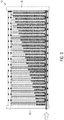
- Figure 9 illustrates that with rapid one-sided filling, more mash is often stored in the rear parts of the mash filter.
- the present invention is based on the object of providing a method for filling plate filters and a membrane which make it possible in a simple manner for unfiltrate to be incorporated homogeneously into an unfiltrate space.
- the at least one membrane is moved during the filling of the unfiltrate space in such a way that the volume of the unfiltrate space increases during filling.
- the volume thus increases at least temporarily during filling or during the entire filling.
- the filter chamber volume increases during filling, a homogeneous structure of the filter cake can be favored and the volume of the unfiltrate space can be adjusted as required. So that the unfiltrate can be adequately stored in the unfiltrate spaces, the volume of which was initially reduced by expansion of the membrane, an at least partial relaxation of the membranes must take place during filling.
- the respective membrane Before or at the beginning of the filling, the respective membrane can be inflated so that it extends into the unfiltrate space.
- the fact that the volume of the unfiltrate space is reduced results in an increased filling rate in the individual unfiltrate spaces. This effectively reduces possible sedimentation and thus promotes even storage. So that a desired volume of unfiltrate can still be stored, the membrane then moves back in such a way that the volume in the unfiltrate space can increase.
- the membrane is inflated before the unfiltrate is introduced into the unfiltrate space.
- the same can also be done at the beginning of the filling (e.g. before 40% of the volume of the unfiltrate space has been filled). The membrane can then be moved back as required.
- the membrane is inflated by passing an inflation medium into an inflation space, the inflation medium being at least partially discharged from the inflation space during filling.
- the pressure in the inflation space is reduced and the membrane can move back to increase the volume of the unfiltered volume. It is very particularly advantageous if so much inflation medium is drained that the pressure in the unfiltrate space remains essentially constant when unfiltrate flows in, where essentially constant means +/- 0.01-0.3 bar or +/- 1 -30%.
- the volume of the unfiltrate space has been reduced by at least 30 percent compared to a state in which there is normal pressure in the inflation space and in the unfiltrate space in such a way that the inflow rate of the unfiltrate increases compared to an uninflated membrane in the unfiltrate space.
- the filling volume in the unfiltrate space can be adjusted in a targeted manner by moving the membrane into the unfiltrate space or out of the unfiltrate space. If, for example, you want to reduce the volume of the unfiltrate space for a certain filter process or a certain filter medium, the pressure in the inflation space is only reduced to such an extent that the volume does not exceed a predetermined volume.
- the pressure in the inflation space can be reduced until the desired volume is reached. It is even possible to apply a negative pressure in the inflation space, so that the volume of the unfiltered space is increased to the maximum.
- the at least one inflatable membrane can preferably be re-inflated and the non-filtrate compressed, with water then preferably being introduced into the non-filtrate space for leaching the filter cake.
- the pressure in the inflating space during filling does not exceed the pressure in the inflating space during compression, in order not to increase the resistance and thus the pressure loss of the filtrate flow to a large extent.
- the plate filter according to the invention comprises a plurality of filter chambers arranged next to one another in the longitudinal direction L with respective unfiltrate spaces which are delimited on at least one side by a flexible, inflatable membrane.
- the device also has a control device which, during the filling of the unfiltrate space, adjusts the pressure in an inflation space such that the volume of the unfiltrate space increases at least temporarily during filling. At least temporarily here means that the membrane is only moved back a certain time after the start of the filling, or that the membrane is not moved further back at a certain maximum volume of the unfiltrate space, but is still filled further.
- the control device can then control at least one corresponding actuator, such as a pump and / or an inlet and / or outlet valve, in order to set a certain pressure in the inflation chamber.
- an input device can be provided, by means of which the pressure profile in the inflation chamber can be entered or selected during filling, in particular before, during and after filling, or in which parameters can be entered and a corresponding profile can be determined and set.
- the inflatable membrane is designed such that it has an outer region which surrounds an inner region, the outer region having a smaller radius of curvature or radius of curvature than the inner region, i.e. for example that the outer area is more elastic than the inner area.
- the inner region advantageously has a greater hardness than the outer region, at least at the points that are braced.
- the inner section does not have to be homogeneous and can have sections of different elasticity.
- a different bending radius can optionally be realized using different materials and / or using different material thicknesses.
- the membrane when the pressure in the inflation space increases, the membrane can move outwards in the direction of the center of the unfiltrate space, the membrane not arching outward in a substantially convex manner, as in the prior art, but the inner region being a compression surface that unites has a larger bending radius.
- the unfiltrate space in the inflated state of the membrane has a substantially constant width in the area of the inner area of the membrane. This makes it possible to store the filter cake more homogeneously and also to press it more homogeneously.
- the inner area is advantageously at least large enough to cover essentially the entire free filter area (+ - 10%) so that it can be compressed evenly. Free filter area is the area that is actively used for filtering, not e.g.
- the surface of a filter element that is clamped in a frame for fastening It is advantageous if the area of the outer area corresponds to 10 to 30 percent of the area of the inner area.
- the membrane with the softer area can then be attached to a filter plate, in particular clamped into a frame, with a free deformation area of the outer area remaining for the reversible deformation when the membranes are inflated.
- the outer region is advantageously a closed, essentially annular, circumferential region with an essentially four-sided inner contour.
- the invention also relates to a membrane which is designed accordingly, as described above.
- a common back pressure ideally an overpressure of e.g. 0.1 to 1 bar can be set in the filtrate drain line (s). This can e.g. can be easily regulated via a bung pressure regulation of an expansion tank.
- FIG 1 shows an embodiment of a filter chamber 1 of a plate filter 10, such as in Figure 3 is shown.
- a plate filter 10 can have a plurality of plates arranged next to one another, here for example filter plates 9 and membrane plates 11, which in a conventional manner are tightly connected to one another via head and end plates 18, 19 (see Figure 3 ) are pressed and connected.
- Figure 1 is just one example of a corresponding structure.
- At least one filter element 3 can be arranged on the filter plates 9 and at least one inflatable membrane 4 can be arranged on the membrane plates 11.
- the plate filter 10 has a plurality of filter chambers 1 arranged next to one another, each of which has an unfiltrate space 2, which is delimited on one side by a membrane 4, and on the other side by a filter element 3, for example a filter cloth, that over a Structured surface 8 is arranged such that the unfiltrate introduced via a filling channel 7 can be filtered by the filter element 3 and can be discharged via a filtrate drain 6.
- an inflation space 5 can be provided, into which inflation medium can be introduced or discharged via an inlet or outlet 12 in order to move the membrane 4.
- Two filter chambers 1 arranged side by side are shown, with two adjacent membranes 4 of two filter chambers 1 share an inflation space 5. When the pressure in the inflation chamber 5 increases, both membranes 4 then move outwards.
- the plate filter 10, as in FIG Figure 12 is shown, advantageously a control device 13, via which at least one actuator 14 is provided for setting a predetermined pressure in the inflation chamber 5.
- a corresponding actuator can, for example, be a pump and / or an inlet and / or outlet valve
- an input device 15 can be provided, by means of which the pressure profile in the inflation chamber 5 can be entered or selected during filling, in particular before, during and after filling, or via which parameters a suitable pressure profile can be determined on the basis of which - e.g. Type and nature of the unfiltrate, filling speed etc. It is also possible that at least one pressure profile has already been saved in the factory and / or cannot be selected.
- the pressure in the inflation chamber 5 can be set via the control device in such a way that the at least one membrane 4 is moved during the filling of the unfiltrate chamber 2 with unfiltrate such that the volume of the unfiltrate chamber 2 changes during filling.
- Figure 11 shows a top view of a conventional elastic inflatable membrane. Furthermore, a longitudinal section through the membrane is shown in the inflated and uninflated state. Again Figure 11 it can be seen that there is a convex curvature, so that when the membrane 4 is inflated and moves in a direction as viewed from the inflation space 5, the unfiltered space 2 has no constant width. In addition, when pressing the filter cake, there is the disadvantage that the filter cake is pressed more strongly in the middle than at the edges. This inhomogeneous compression leads to different filter cake resistances within the filter cake, which is leached out unevenly with washing liquid.
- the membranes can either be clamped on appropriate plates or welded to corresponding plates.
- the membrane 4 is as in Figure 4 is divided into at least two different areas A, B, which are integrally connected.
- the outer, more flexible area A is approximately large enough that the membrane 4 can be attached, for example, to a frame-like plate or can be clamped between two adjacent frame-like plates and thus seal the adjacent plates against one another. As the section through the membrane 4 shows, this results in a circumferential sealing surface 16.
- a circumferential deformation region 17 remains of the outer region A, which is turned upward from the inflation space 5 when the membranes 4 are inflated.
- the inner less flexible area B has a larger bending radius when inflated and remains essentially straight or has a smaller bending radius.
- Several areas (> 2) can also be provided which can be stretched differently.
- the outer area A can have a Shore hardness of 40 to 70 ShA (according to DIN EN ISO 868, DIN ISO 7619-1 and ASTM D2240-00 ) and the inner harder area B a Shore hardness of 60 to 80 ShA , or 40 to 90 ShD.
- the difference in hardness of the two areas should advantageously be at least 5 ShA, preferably at least 10 ShA.
- a different bending radius during inflation can also be achieved via the thickness of the membrane 4, for example by the inner region B being substantially thicker than the circumferential outer region A.
- the outer region A is as from Figure 4 emerges in particular ring-shaped with a four-sided inner contour, preferably with rounded corners.
- EPDM, NBR, PP and PA and composite materials made of these can preferably be used as the material for the membrane.
- the filter cake it is possible to store the filter cake more homogeneously and to compress it more homogeneously. Uniform compression of the filter cake over the entire filter surface enables the filter cake to be homogeneously leached out, thereby increasing the efficiency of the plate filter with regard to washing out the filter cake.
- the entire membrane 4 can be designed specifically for the different tasks, sealing the filter plate 9 and membrane plate 11 against one another, as well as expansion for compression of the filter cake formed.
- a corresponding clampable membrane can also be easily retrofitted into existing systems, and can be replaced more quickly and cost-effectively compared to welded membranes.
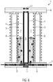
- Figure 5 shows, for example, two filter chambers before filling, normal pressure prevailing for example in the inflation space 5 and in the unfiltrate spaces 2, so that the membranes 4 extend essentially vertically.
- inflation medium is introduced into the inflation space 5 via the inlet 12 for inflation media.
- a corresponding actuator 14 can be controlled by the control device 13 so that a certain pressure is established in the inflation chamber 5.
- a corresponding pressure or a speaking pressure profile during filling, or corresponding parameters can be entered via an input device 15, or a corresponding pressure profile is stored in the control device 13 and can be selected via the input device 15, or is set automatically.
- the respective membrane 4 of the filter chambers 1 is moved outward from the inflation space 5 at least to such an extent that the volume of the unfiltrate space 2 is reduced by at least 30 percent compared to a state in which normal pressure prevails in the inflation space 5 and in the unfiltrate space 2, ie the membrane 4 runs essentially vertically, as in FIG Figure 5 is shown.
- the membrane 4 can advantageously be inflated appropriately before filling or even at the beginning of the filling, i.e. if e.g. less than 40% of the unfiltrate was stored in the respective unfiltrate spaces, at the latest until the unfiltrate penetrates from the filling channel 7 into the unfiltrate space 2.
- the pressure during the filling is essentially set in the inflation chamber 5 such that the pressure in the unfiltrate chamber 2 is kept essentially constant, that is to say that the filling is ideally carried out by counterpressure control in order to control the extent of the membrane relaxation.
- the pressure profile during filling can, for example, be calculated in advance depending on the filling quantity per time, the structural dimensions and material properties of the membrane. It is also possible to measure the pressure in the unfiltrate space 2 during filling and to regulate the pressure in the inflation space 5 accordingly.
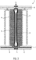
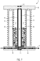
- Figure 2 equals to Figure 1 , here more unfiltrate has already been introduced into the unfiltrate space 2 and filtrate is already running out through the filtrate outlet 6, the unfiltrate space 2 having already increased due to the movement of the membrane 4.
- the membrane 4 moves back until a predetermined maximum unfiltered volume volume is reached.
- the volume of the unfiltrate space 2 i.e. the maximum or minimum volume can be set.
- a negative pressure can also be applied in the inflation space 5.
- the membrane 4 as in connection with the Figure 4 has been described, there is an essentially constant width of the unfiltrate space 2 in the area which corresponds to the inner area B. This is advantageous for a uniform storage in the unfiltrate space 2 and ensures a uniform compression when the filter cake is pressed out.
- the cake is ideally pressed and the water is subsequently introduced to leach out the filter cake.
- inflation medium is again conducted into the inflation space 5 so that the membrane 4, here the two membranes 4, move outward from the inflation space 5, that is to say in the direction of the unfiltrate spaces. If necessary, this process can be repeated several times before the filter chambers 1 are emptied either by moving the plates 1 apart or by opening a bottom opening (not shown). It is advantageous that the back pressure in the inflating space 5 when filling the unfiltrate space 2 does not exceed the pressure in the inflating space 5 during pressing.
- the method according to the invention enables homogeneous loading of all chambers of the plate filter. Sedimentation can be effectively avoided.
- a common back pressure ideally an overpressure of, for example, 0.1 to 1 bar can be set in the filtrate drain line or lines. This can be easily regulated, for example, by regulating the pressure of a surge tank.
- the method according to the invention is not limited to the plate filter 10 described above, but is equally suitable for all plate filters, in particular mash filters, which use at least one inflatable membrane 4 per filter chamber 1.
- the method according to the invention is also suitable if the chambers 1 have two membranes 4, the unfiltrate spaces can be opened downwards through a bottom opening and / or the filter is operated continuously or batchwise.
- the structured surface 8 it is also possible, as an alternative or in addition, for the structured surface 8 to be designed as an inflatable membrane 4 which can be inflated via an alternative or additional inflation space 5 and which has the above-mentioned functions and properties.
Landscapes
- Chemical & Material Sciences (AREA)
- Chemical Kinetics & Catalysis (AREA)
- Separation Using Semi-Permeable Membranes (AREA)
Applications Claiming Priority (1)
| Application Number | Priority Date | Filing Date | Title |
|---|---|---|---|
| DE102018219126.3A DE102018219126A1 (de) | 2018-11-09 | 2018-11-09 | Verfahren zum Befüllen von Plattenfiltern |
Publications (2)
| Publication Number | Publication Date |
|---|---|
| EP3650098A2 true EP3650098A2 (fr) | 2020-05-13 |
| EP3650098A3 EP3650098A3 (fr) | 2020-07-29 |
Family
ID=68242439
Family Applications (1)
| Application Number | Title | Priority Date | Filing Date |
|---|---|---|---|
| EP19202167.3A Withdrawn EP3650098A3 (fr) | 2018-11-09 | 2019-10-09 | Procédé de remplissage de filtres à plaque |
Country Status (2)
| Country | Link |
|---|---|
| EP (1) | EP3650098A3 (fr) |
| DE (1) | DE102018219126A1 (fr) |
Cited By (3)
| Publication number | Priority date | Publication date | Assignee | Title |
|---|---|---|---|---|
| CN113545490A (zh) * | 2021-07-27 | 2021-10-26 | 广西壮族自治区农业科学院 | 一种火龙果去籽装置 |
| DE102021133455A1 (de) | 2021-12-16 | 2023-06-22 | Steinecker GmbH | Maischefilter und Verfahren zum Filtrieren von Maische |
| CN116507397A (zh) * | 2020-07-02 | 2023-07-28 | Jvk过滤系统有限公司 | 过滤板 |
Family Cites Families (7)
| Publication number | Priority date | Publication date | Assignee | Title |
|---|---|---|---|---|
| EP0149820A3 (fr) * | 1981-12-15 | 1986-09-10 | Klinkau & Co. GmbH | Plaque filtrante à membrane pour filtre-presse |
| DE3504152A1 (de) * | 1985-02-07 | 1986-08-07 | Grau Feinwerktechnik GmbH & Co, 7926 Böhmenkirch | Verfahren zum trennen einer suspension unter druck in einer filterpresse mit membranfilterkammern |
| EP2248571A1 (fr) * | 2009-05-05 | 2010-11-10 | Meura S.A. | Filtres-presse à membranes et procédé de filtration |
| BE1022954B1 (fr) * | 2015-08-21 | 2016-10-21 | Meura S.A. | Filtre-presse a membrane et procede de filtration |
| DE102017215928A1 (de) * | 2017-09-08 | 2019-03-14 | Krones Aktiengesellschaft | Plattenfilter und Verfahren zum Filtrieren von Maische |
| DE102017215930A1 (de) * | 2017-09-08 | 2019-03-14 | Krones Aktiengesellschaft | Vorrichtung und Verfahren zum Maischen und Filtrieren für die Bierherstellung |
| DE102017215925A1 (de) * | 2017-09-08 | 2019-03-14 | Krones Aktiengesellschaft | Filtrationsverfahren und Plattenfilter |
-
2018
- 2018-11-09 DE DE102018219126.3A patent/DE102018219126A1/de not_active Withdrawn
-
2019
- 2019-10-09 EP EP19202167.3A patent/EP3650098A3/fr not_active Withdrawn
Cited By (3)
| Publication number | Priority date | Publication date | Assignee | Title |
|---|---|---|---|---|
| CN116507397A (zh) * | 2020-07-02 | 2023-07-28 | Jvk过滤系统有限公司 | 过滤板 |
| CN113545490A (zh) * | 2021-07-27 | 2021-10-26 | 广西壮族自治区农业科学院 | 一种火龙果去籽装置 |
| DE102021133455A1 (de) | 2021-12-16 | 2023-06-22 | Steinecker GmbH | Maischefilter und Verfahren zum Filtrieren von Maische |
Also Published As
| Publication number | Publication date |
|---|---|
| DE102018219126A1 (de) | 2020-05-14 |
| EP3650098A3 (fr) | 2020-07-29 |
Similar Documents
| Publication | Publication Date | Title |
|---|---|---|
| DE10012186A1 (de) | Filtervorrichtung mit Rückwaschmechanismus | |
| DE102018219126A1 (de) | Verfahren zum Befüllen von Plattenfiltern | |
| DE102011111457A1 (de) | Filtervorrichtung | |
| EP3678754A1 (fr) | Presse à filtre à plaques et procédé de filtration dans lequel elle est employée | |
| EP2602016B1 (fr) | Installation de nettoyage de filtres et procédé d'actionnement d'une installation de nettoyage de filtres | |
| DE1461452A1 (de) | Verfahren zum Filtrieren | |
| DE1146479B (de) | Filtervorrichtung | |
| WO2019048472A1 (fr) | Filtre à plaques et procédé de filtration de la maische | |
| DE102011018478A1 (de) | Verfahren zur Rückspülung von Filtrationsmodulen und Filtrationsanlage | |
| WO2020094282A1 (fr) | Plaque filtrante en forme de cassette pour filtre horizontal | |
| DE2244917C3 (de) | Verfahren und Vorrichtung zum Beschicken einer Filtervorrichtung | |
| EP1358921A1 (fr) | Filtre-presse à chambres à membrane | |
| EP0003593B1 (fr) | Procédé et appareil pour la filtration d'une boue ou matière analogue dans un filtre-presse | |
| DE19607740A1 (de) | Verfahren zur Steuerung von Filtrationsanlagen | |
| DE1295518B (de) | Bandfilter | |
| DE2628237A1 (de) | Durchflusskoerper in von fluessigkeiten oder gasen durchstroemten raeumen | |
| AT225720B (de) | Vorrichtung und Verfahren zum Auspressen von Flüssigkeit aus flüssigkeitshaltigem, feinkörnigem Gut, wie Kohlenschlamm u. dgl. | |
| DE1536844A1 (de) | Filterpresse | |
| AT410076B (de) | Vorrichtung und verfahren zur filterung von viskosem material | |
| DE4033868C2 (fr) | ||
| DE202023107316U1 (de) | Zweiseitig gespeister Maischefilter | |
| EP4674501A1 (fr) | Procédé de traitement d'eaux usées et installation de traitement d'eaux usées | |
| DE2412007A1 (de) | Filter fuer wasseraufbereitungsanlagen | |
| WO2023213599A1 (fr) | Dispositif de filtration | |
| CH534535A (de) | Klärfilter |
Legal Events
| Date | Code | Title | Description |
|---|---|---|---|
| PUAI | Public reference made under article 153(3) epc to a published international application that has entered the european phase |
Free format text: ORIGINAL CODE: 0009012 |
|
| STAA | Information on the status of an ep patent application or granted ep patent |
Free format text: STATUS: THE APPLICATION HAS BEEN PUBLISHED |
|
| AK | Designated contracting states |
Kind code of ref document: A2 Designated state(s): AL AT BE BG CH CY CZ DE DK EE ES FI FR GB GR HR HU IE IS IT LI LT LU LV MC MK MT NL NO PL PT RO RS SE SI SK SM TR |
|
| AX | Request for extension of the european patent |
Extension state: BA ME |
|
| PUAL | Search report despatched |
Free format text: ORIGINAL CODE: 0009013 |
|
| AK | Designated contracting states |
Kind code of ref document: A3 Designated state(s): AL AT BE BG CH CY CZ DE DK EE ES FI FR GB GR HR HU IE IS IT LI LT LU LV MC MK MT NL NO PL PT RO RS SE SI SK SM TR |
|
| AX | Request for extension of the european patent |
Extension state: BA ME |
|
| RIC1 | Information provided on ipc code assigned before grant |
Ipc: B01D 25/30 20060101ALI20200622BHEP Ipc: B01D 25/28 20060101ALI20200622BHEP Ipc: B01D 25/164 20060101AFI20200622BHEP |
|
| STAA | Information on the status of an ep patent application or granted ep patent |
Free format text: STATUS: THE APPLICATION IS DEEMED TO BE WITHDRAWN |
|
| 18D | Application deemed to be withdrawn |
Effective date: 20210130 |