EP3650126A2 - Système de distribution multifluides et procédé associé - Google Patents
Système de distribution multifluides et procédé associé Download PDFInfo
- Publication number
- EP3650126A2 EP3650126A2 EP19184531.2A EP19184531A EP3650126A2 EP 3650126 A2 EP3650126 A2 EP 3650126A2 EP 19184531 A EP19184531 A EP 19184531A EP 3650126 A2 EP3650126 A2 EP 3650126A2
- Authority
- EP
- European Patent Office
- Prior art keywords
- receptacle
- cic
- component
- type receptacle
- preform
- Prior art date
- Legal status (The legal status is an assumption and is not a legal conclusion. Google has not performed a legal analysis and makes no representation as to the accuracy of the status listed.)
- Withdrawn
Links
Images


Classifications
-
- B—PERFORMING OPERATIONS; TRANSPORTING
- B29—WORKING OF PLASTICS; WORKING OF SUBSTANCES IN A PLASTIC STATE IN GENERAL
- B29C—SHAPING OR JOINING OF PLASTICS; SHAPING OF MATERIAL IN A PLASTIC STATE, NOT OTHERWISE PROVIDED FOR; AFTER-TREATMENT OF THE SHAPED PRODUCTS, e.g. REPAIRING
- B29C49/00—Blow-moulding, i.e. blowing a preform or parison to a desired shape within a mould; Apparatus therefor
- B29C49/22—Blow-moulding, i.e. blowing a preform or parison to a desired shape within a mould; Apparatus therefor using multilayered preforms or parisons
-
- B—PERFORMING OPERATIONS; TRANSPORTING
- B05—SPRAYING OR ATOMISING IN GENERAL; APPLYING FLUENT MATERIALS TO SURFACES, IN GENERAL
- B05B—SPRAYING APPARATUS; ATOMISING APPARATUS; NOZZLES
- B05B11/00—Single-unit hand-held apparatus in which flow of contents is produced by the muscular force of the operator at the moment of use
- B05B11/0005—Components or details
- B05B11/0078—Arrangements for separately storing several components
-
- B—PERFORMING OPERATIONS; TRANSPORTING
- B05—SPRAYING OR ATOMISING IN GENERAL; APPLYING FLUENT MATERIALS TO SURFACES, IN GENERAL
- B05B—SPRAYING APPARATUS; ATOMISING APPARATUS; NOZZLES
- B05B11/00—Single-unit hand-held apparatus in which flow of contents is produced by the muscular force of the operator at the moment of use
- B05B11/01—Single-unit hand-held apparatus in which flow of contents is produced by the muscular force of the operator at the moment of use characterised by the means producing the flow
- B05B11/02—Membranes or pistons acting on the contents inside the container, e.g. follower pistons
- B05B11/026—Membranes separating the content remaining in the container from the atmospheric air to compensate underpressure inside the container
-
- B—PERFORMING OPERATIONS; TRANSPORTING
- B05—SPRAYING OR ATOMISING IN GENERAL; APPLYING FLUENT MATERIALS TO SURFACES, IN GENERAL
- B05B—SPRAYING APPARATUS; ATOMISING APPARATUS; NOZZLES
- B05B11/00—Single-unit hand-held apparatus in which flow of contents is produced by the muscular force of the operator at the moment of use
- B05B11/01—Single-unit hand-held apparatus in which flow of contents is produced by the muscular force of the operator at the moment of use characterised by the means producing the flow
- B05B11/10—Pump arrangements for transferring the contents from the container to a pump chamber by a sucking effect and forcing the contents out through the dispensing nozzle
- B05B11/1001—Piston pumps
- B05B11/1009—Piston pumps actuated by a lever
- B05B11/1011—Piston pumps actuated by a lever without substantial movement of the nozzle in the direction of the pressure stroke
-
- B—PERFORMING OPERATIONS; TRANSPORTING
- B05—SPRAYING OR ATOMISING IN GENERAL; APPLYING FLUENT MATERIALS TO SURFACES, IN GENERAL
- B05B—SPRAYING APPARATUS; ATOMISING APPARATUS; NOZZLES
- B05B11/00—Single-unit hand-held apparatus in which flow of contents is produced by the muscular force of the operator at the moment of use
- B05B11/01—Single-unit hand-held apparatus in which flow of contents is produced by the muscular force of the operator at the moment of use characterised by the means producing the flow
- B05B11/10—Pump arrangements for transferring the contents from the container to a pump chamber by a sucking effect and forcing the contents out through the dispensing nozzle
- B05B11/1042—Components or details
- B05B11/1043—Sealing or attachment arrangements between pump and container
- B05B11/1046—Sealing or attachment arrangements between pump and container the pump chamber being arranged substantially coaxially to the neck of the container
- B05B11/1047—Sealing or attachment arrangements between pump and container the pump chamber being arranged substantially coaxially to the neck of the container the pump being preassembled as an independent unit before being mounted on the container
-
- B—PERFORMING OPERATIONS; TRANSPORTING
- B29—WORKING OF PLASTICS; WORKING OF SUBSTANCES IN A PLASTIC STATE IN GENERAL
- B29B—PREPARATION OR PRETREATMENT OF THE MATERIAL TO BE SHAPED; MAKING GRANULES OR PREFORMS; RECOVERY OF PLASTICS OR OTHER CONSTITUENTS OF WASTE MATERIAL CONTAINING PLASTICS
- B29B11/00—Making preforms
- B29B11/14—Making preforms characterised by structure or composition
-
- B—PERFORMING OPERATIONS; TRANSPORTING
- B29—WORKING OF PLASTICS; WORKING OF SUBSTANCES IN A PLASTIC STATE IN GENERAL
- B29C—SHAPING OR JOINING OF PLASTICS; SHAPING OF MATERIAL IN A PLASTIC STATE, NOT OTHERWISE PROVIDED FOR; AFTER-TREATMENT OF THE SHAPED PRODUCTS, e.g. REPAIRING
- B29C49/00—Blow-moulding, i.e. blowing a preform or parison to a desired shape within a mould; Apparatus therefor
- B29C49/071—Preforms or parisons characterised by their configuration, e.g. geometry, dimensions or physical properties
-
- B—PERFORMING OPERATIONS; TRANSPORTING
- B29—WORKING OF PLASTICS; WORKING OF SUBSTANCES IN A PLASTIC STATE IN GENERAL
- B29C—SHAPING OR JOINING OF PLASTICS; SHAPING OF MATERIAL IN A PLASTIC STATE, NOT OTHERWISE PROVIDED FOR; AFTER-TREATMENT OF THE SHAPED PRODUCTS, e.g. REPAIRING
- B29C2949/00—Indexing scheme relating to blow-moulding
- B29C2949/07—Preforms or parisons characterised by their configuration
- B29C2949/0715—Preforms or parisons characterised by their configuration the preform having one end closed
-
- B—PERFORMING OPERATIONS; TRANSPORTING
- B29—WORKING OF PLASTICS; WORKING OF SUBSTANCES IN A PLASTIC STATE IN GENERAL
- B29C—SHAPING OR JOINING OF PLASTICS; SHAPING OF MATERIAL IN A PLASTIC STATE, NOT OTHERWISE PROVIDED FOR; AFTER-TREATMENT OF THE SHAPED PRODUCTS, e.g. REPAIRING
- B29C2949/00—Indexing scheme relating to blow-moulding
- B29C2949/07—Preforms or parisons characterised by their configuration
- B29C2949/076—Preforms or parisons characterised by their configuration characterised by the shape
- B29C2949/0768—Preforms or parisons characterised by their configuration characterised by the shape characterised by the shape of specific parts of preform
- B29C2949/077—Preforms or parisons characterised by their configuration characterised by the shape characterised by the shape of specific parts of preform characterised by the neck
-
- B—PERFORMING OPERATIONS; TRANSPORTING
- B29—WORKING OF PLASTICS; WORKING OF SUBSTANCES IN A PLASTIC STATE IN GENERAL
- B29C—SHAPING OR JOINING OF PLASTICS; SHAPING OF MATERIAL IN A PLASTIC STATE, NOT OTHERWISE PROVIDED FOR; AFTER-TREATMENT OF THE SHAPED PRODUCTS, e.g. REPAIRING
- B29C2949/00—Indexing scheme relating to blow-moulding
- B29C2949/07—Preforms or parisons characterised by their configuration
- B29C2949/079—Auxiliary parts or inserts
- B29C2949/08—Preforms made of several individual parts, e.g. by welding or gluing parts together
-
- B—PERFORMING OPERATIONS; TRANSPORTING
- B29—WORKING OF PLASTICS; WORKING OF SUBSTANCES IN A PLASTIC STATE IN GENERAL
- B29C—SHAPING OR JOINING OF PLASTICS; SHAPING OF MATERIAL IN A PLASTIC STATE, NOT OTHERWISE PROVIDED FOR; AFTER-TREATMENT OF THE SHAPED PRODUCTS, e.g. REPAIRING
- B29C2949/00—Indexing scheme relating to blow-moulding
- B29C2949/30—Preforms or parisons made of several components
- B29C2949/3008—Preforms or parisons made of several components at neck portion
-
- B—PERFORMING OPERATIONS; TRANSPORTING
- B29—WORKING OF PLASTICS; WORKING OF SUBSTANCES IN A PLASTIC STATE IN GENERAL
- B29C—SHAPING OR JOINING OF PLASTICS; SHAPING OF MATERIAL IN A PLASTIC STATE, NOT OTHERWISE PROVIDED FOR; AFTER-TREATMENT OF THE SHAPED PRODUCTS, e.g. REPAIRING
- B29C2949/00—Indexing scheme relating to blow-moulding
- B29C2949/30—Preforms or parisons made of several components
- B29C2949/3012—Preforms or parisons made of several components at flange portion
-
- B—PERFORMING OPERATIONS; TRANSPORTING
- B29—WORKING OF PLASTICS; WORKING OF SUBSTANCES IN A PLASTIC STATE IN GENERAL
- B29C—SHAPING OR JOINING OF PLASTICS; SHAPING OF MATERIAL IN A PLASTIC STATE, NOT OTHERWISE PROVIDED FOR; AFTER-TREATMENT OF THE SHAPED PRODUCTS, e.g. REPAIRING
- B29C2949/00—Indexing scheme relating to blow-moulding
- B29C2949/30—Preforms or parisons made of several components
- B29C2949/3016—Preforms or parisons made of several components at body portion
-
- B—PERFORMING OPERATIONS; TRANSPORTING
- B29—WORKING OF PLASTICS; WORKING OF SUBSTANCES IN A PLASTIC STATE IN GENERAL
- B29C—SHAPING OR JOINING OF PLASTICS; SHAPING OF MATERIAL IN A PLASTIC STATE, NOT OTHERWISE PROVIDED FOR; AFTER-TREATMENT OF THE SHAPED PRODUCTS, e.g. REPAIRING
- B29C2949/00—Indexing scheme relating to blow-moulding
- B29C2949/30—Preforms or parisons made of several components
- B29C2949/302—Preforms or parisons made of several components at bottom portion
-
- B—PERFORMING OPERATIONS; TRANSPORTING
- B29—WORKING OF PLASTICS; WORKING OF SUBSTANCES IN A PLASTIC STATE IN GENERAL
- B29C—SHAPING OR JOINING OF PLASTICS; SHAPING OF MATERIAL IN A PLASTIC STATE, NOT OTHERWISE PROVIDED FOR; AFTER-TREATMENT OF THE SHAPED PRODUCTS, e.g. REPAIRING
- B29C2949/00—Indexing scheme relating to blow-moulding
- B29C2949/30—Preforms or parisons made of several components
- B29C2949/3086—Interaction between two or more components, e.g. type of or lack of bonding
- B29C2949/3094—Interaction between two or more components, e.g. type of or lack of bonding preform having at least partially loose components, e.g. at least partially loose layers
-
- B—PERFORMING OPERATIONS; TRANSPORTING
- B29—WORKING OF PLASTICS; WORKING OF SUBSTANCES IN A PLASTIC STATE IN GENERAL
- B29L—INDEXING SCHEME ASSOCIATED WITH SUBCLASS B29C, RELATING TO PARTICULAR ARTICLES
- B29L2009/00—Layered products
- B29L2009/001—Layered products the layers being loose
-
- B—PERFORMING OPERATIONS; TRANSPORTING
- B29—WORKING OF PLASTICS; WORKING OF SUBSTANCES IN A PLASTIC STATE IN GENERAL
- B29L—INDEXING SCHEME ASSOCIATED WITH SUBCLASS B29C, RELATING TO PARTICULAR ARTICLES
- B29L2031/00—Other particular articles
- B29L2031/712—Containers; Packaging elements or accessories, Packages
- B29L2031/7158—Bottles
Definitions
- the invention relates to a multilayer "container in container” receptacle, particularly to a multi-chamber one, and to a preform-set for making said receptacle.
- the invention also relates to a method for producing a multi-chamber multilayer "container in container” receptacle.
- the invention additionally relates to an atomizer compatible with multi-chamber multilayer "container in container” receptacles, said atomizer being capable of dispersing at least two fluids.
- the invention further relates to a system consisting of a multi-chamber multilayer "container in container” receptacle, and an atomizer, both components of said system being made according to this invention.
- Multi-chamber receptacles allow storing inside a single receptacle of two or more substances; the dispensing of stored substances may take place either simultaneously or separately.
- Multi-chamber receptacles can have varied areas of use, one of the most common being that of cleaning chemicals - both household cleaning and commercial or industrial-type cleaning. Another area of use of multi-chamber receptacles could be - for example but not limited to - that of carbonated drinks.
- WO2009088285A1 a way to obtain two storage-compartments within a multilayer "container in container” receptacle is indicated.
- the said multilayer "container in container” receptacle consists of three constituent containers/ component-units: an external/ outermost component-unit, an intermediate component-unit and an internal/ innermost component-unit. Following a delamination of its external structure, within said "container in container” receptacle two storage-compartments may be obtained.
- One of the two storage-compartments is delimited by the inner surface of the walls of the internal component-unit, and a second one is flanked by both the exterior surface of the walls of the internal component-unit and the inner surface of the walls of the intermediate component-unit.
- the internal component-unit - with the contained liquid - should be for the most part submerged in the liquid held by the intermediate component-unit.
- the two storage-compartments of said receptacle are therefore not individual. As an effect, it may be difficult to adequately manage the two liquids.
- the said receptacle should allow airless liquid-storing and 360 degrees operation of a dispensing system or device of which said receptacle may be a part, all without utilizing specialized additional components. It is equally an object of present invention to provide at least a method of producing said multi-chamber multilayer "container in container” receptacle.
- two storage-compartments can be obtained within a multilayer "container in container” receptacle (or CIC-type receptacle) consisting of three constituent containers/ component-units by transforming the internal/ innermost component-unit of a said CIC-type receptacle into a partitioning-system.
- a delamination process certain lateral areas of the walls of said internal component-unit may be repositioned in the longitudinal median region of said CIC-type receptacle.
- This particular configuring stage of a CIC-type receptacle which includes both of the previously indicated delamination and repositioning processes, may well be carried out during the liquid-bottling phase of a CIC-type receptacle, even utilizing the liquids being bottled.
- the partitioning-system hence obtained, a double-walled one, should hence separate two individual, independent, and possibly symmetrical storage-compartments located on the lateral sides of a said CIC-type receptacle.
- a decrease in the volume of the storage-compartments should occur during the cycle-of-use.
- the said decrease may be accomplished by means of compressing those said storage-compartments.
- the said compressing may be achieved by delaminating and progressively repositioning certain lateral areas of the walls of the intermediate component-unit, which said walls partake in delimiting the storage-compartments.
- X represents the longitudinal axis
- Y the lateral axis
- Z the vertical axis.
- M indicates the median (the middle) of a CIC-type receptacle, or a preform-set, or an atomizer, or a dispensing system, in relation to the longitudinal axis X.
- lateral parts, components, areas, regions, sides etc. located on one side or the other of the median M.
- a multi-chamber receptacle means a receptacle having therein more than a storage-compartment.
- a multilayer "container in container” receptacle made according to this invention - essentially a multilayer/ composite/ laminate container, possibly a multi-chamber one - is predominantly called a CIC-type receptacle.
- the term CIC-type receptacle is used for such receptacles without regard to their configuration phase, i.e. both before and after the compartmentation.
- cycle-of-use means the period between starting using a CIC-type receptacle, or a system, or a device of which said receptacle may be a part, and the fluid-exhaustion of a said CIC-type receptacle.
- the term operation(s) with its derivatives operating, operate etc. may be used in relation to certain processes - such as, but not limited to, the repositioning or moving of certain parts, surfaces or components of a CIC-type receptacle - both during the "cycle-of-use", but also prior to that stage (i.e. while configuring the storage-compartments etc.).
- blow-molding transforming a preform or preform-set into a receptacle - a process that requires at least reheating, stretching and then the blowing - is called blow-molding.
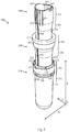
- Fig. 1 illustrates a perspective view of a dispensing system 100 comprising a CIC-type receptacle 300 and an atomizer 500.
- a CIC-type receptacle 300 is composed of three constituent containers henceforward called component-units: one external component-unit (the outermost one), one intermediate component-unit (the middle one) and one internal component-unit (the innermost one). Said three component-units form together a multilayer/ composite/ laminate structure.
- a CIC-type receptacle 300 is obtained from a preform-set 200 ( Fig. 2 ), following a blow-molding process.
- the preform-set 200 is constituted by assembling the component-preforms: the external component-preform 220, the intermediate component-preform 240 and the internal component-preform 260, Fig. 2 , Fig. 3a-3c .
- component-preforms 220, 240 and 260 may be identified a series of vertical segments with specific roles.
- the corresponding upper-segments 221, 241 and 261 may incorporate - right from the production phase of their respective component-preforms, i.e. 220, 240, and 260 - a number of functional elements required at least in one of the ensuing stages involving a CIC-type receptacle 300: blow-molding, compartmentation and/ or liquid-bottling, but also during the assembly and/ or use of a dispensing system 100.
- flange 229 and stiffening members 230 are functional-forms acting as folding elements, Fig. 2 (the functional-forms will be detailed later).
- grooves 265 are functional-forms acting as folding elements, Fig. 2 (the functional-forms will be detailed later).
- Other functional elements present at the level of the upper-segments 221, 241 and 261 will be identified as the description progresses.
- the corresponding upper-segments 221, 241, and 261 of the component-preforms 220, 240 and 260 are non-transformable during the blow-molding process.
- the geometry of the top end of said preform-set 200 - the part incorporating the upper-segments 221, 241, and 261 - should be identical to that of the upper-segment 301 of a CIC-type receptacle 300 ( Fig. 4a ).
- the corresponding intermediate-segments 222, 242 and 262 of the component-preforms 220, 240 and 260 may be fashioned as transitional segments that tolerate certain shape transformations during the blow-molding process; functional elements possibly integrated into the structure of these segments may also suffer some shape transformations.
- the corresponding lower-segments 223, 243 and 263 of the component-preforms 220, 240 and 260 allow extensive shape transformations during the blow-molding process.
- the component-preforms 220, 240 and 260 can be manufactured individually by injection molding or by means of alternative methods - for example 3D printing.
- the component-preforms - all or only some of them - may also be produced as a unitary structure obtained via, for example but not exclusively, a sandwich-type injection.
- the geometry of the component-preforms 220, 240 and 260 may differ from the circular shape illustrated in the drawings related to the description of the invention.
- General geometry may differ from one component-preform - i.e. 220, 240 and 260 - to another.
- the permanent-joint should be performed between at least two of the three component-preforms (i.e. 220, 240 and 260) of the preform-set 200 and it should subsequently emerge in the structure of a CIC-type receptacle 300 as permanent-joint 382 ( Fig. 1 ).
- the indicated permanent-joint 382 may preferably be executed on the median M of said preform-set 200 with adhesive and/ or welding, preferably vertically or substantially vertically.
- said adhesive may be deposited in the form of lines or stripes located, for example, as follows ( Fig. 2 , Fig. 3a-3b ): 233, on the inside of the external component-preform 220; 246 and 247, on the outside and respectively on the inside of the intermediate component-preform 240; 266, on the outside of the internal component-preform 260. In practice it is not necessary to execute all four lines or stripes 233, 246, 247 and 266.
- a permanent-joint can also be achieved by means of welding (not illustrated).
- the permanent-joint by welding can be executed as well on the median M of the preform-set 200, either after completion of a partial assembly - so between only two of the component-preforms (i.e. 220, 240 and 260) - or after the main assembly of the preform-set 200.
- Welding can be performed, for instance, by ultrasound, laser or other methods.
- the preform-set 200 described above is subsequently subjected to a blow-molding process.
- the blow-molding process may be a conventional one, attained within a mold and using compressed air.
- the preform-set 200 is transformed into a CIC-type receptacle 300 ( Fig. 1 ).
- the component-preforms of the preform-set 200 i.e. external component-preform 220, intermediate component-preform 240 and internal component-preform 260
- Fig. 4a-4b illustrate the upper-segment 301 of such CIC-type receptacle 300, practically the neck area of said receptacle and the opening at the top of it.
- two storage-compartments can be obtained within a CIC-type receptacle 300 by transforming certain lateral areas of the walls of the internal component-unit 360 into a partitioning-system.
- Those said certain lateral areas of the walls of the internal component-unit 360 may stem from side-sections 306 of a CIC-type receptacle 300 and possibly also from slanted-sections 305.
- those certain lateral areas of said walls of the internal component-unit 360 should first be separated from the multilayer external structure of a CIC-type receptacle 300 - practically from the walls of the intermediate component-unit 340 - through a delamination process.
- those certain lateral areas of the walls of the internal component-unit 360 are then forced towards the region of the median M of a CIC-type receptacle 300, following directions A1 and A2 ( Fig. 6a ).
- those certain lateral areas of the walls of the internal component-unit 360 at least relatively reach the region of the median M of a CIC-type receptacle 300, a double-walled partitioning-system 361 is formed.
- the configuring of a CIC-type receptacle 300 may be carried out during the liquid-bottling stage of that said CIC-type receptacle 300, even utilizing the liquids being bottled.
- liquid-storing should be airless, without contact between stored substances and the atmospheric air.
- a dispensing system of which a CIC-type receptacle 300 may be a part - i.e. the dispensing system 100 - should be able to operate at 360 degrees without utilizing specialized additional components.
- the storing capacity of the storage-compartments 310 - essentially the volume of each such storage-compartment - should gradually decrease during the cycle-of-use, in proportion to the consumption of the liquids stored therein.
- the said decrease in the storing capacity of the storage-compartments 310 may be accomplished by means of compressing those said storage-compartments 310 during the cycle-of-use.
- the said compressing may be achieved by delaminating and progressively repositioning - also on directions A1 and A2, towards the region of the median M - certain lateral areas of the walls of the intermediate component-unit 340, which said walls partake in delimiting the storage-compartments 310.
- Those said certain lateral areas of the walls of the intermediate component-unit 340 may stem from the side-sections 306 of a CIC-type receptacle 300 and possibly also from the slanted-sections 305.
- the compression-system 341 essentially squeezes, crushes, the storage-compartments 310 during the cycle-of-use.
- the void-spaces 311 should progressively emerge on the other side of the walls of the compression-system 341.
- the said void-spaces 311 should thus be formed between the walls of the compression-system 341 and the walls of the external component-unit 320 ( Fig. 6b and Fig. 7 ).
- the said void-spaces 311 may be filled with atmospheric air just as they develop.
- the compression-system 341 - in contrast to the rapid configuration of the partitioning-system 361 - exhibits a progressive, slow operation, throughout the entire cycle-of-use of a CIC-type receptacle 300.
- the action of the compression-system 341 on storage-compartments 310 represents an effect of the internal pressure balancing process inside a CIC-type receptacle 300.
- the fluid-exhaustion of storage-compartments 310 should lead to the actual complete disappearance of said storage-compartments 310; the walls of the compression-system 341 should thus end up by being superimposed over those of the partitioning-system 361 ( Fig. 6b ).
- the mobile-sectors of both the internal component-unit 360 and the intermediate component-unit 340 emerge by means of delamination of the multilayer exterior structure of a CIC-type receptacle 300. Ensuing the delamination process, the mobile-sectors are subjected to a repositioning process within said CIC-type receptacle 300. Preferably, both the above-mentioned processes involving the mobile-sectors - i.e. delamination and repositioning - should occur in a controlled manner.
- the multilayer external structure of a CIC-type receptacle 300 should preferably feature:
- the operational-sections of a CIC-type receptacle 300 may include:
- the operational-sections may be delimited via (i) certain types of functional-forms inserted in the external structure of a CIC-type receptacle 300 and also by means of (ii) general design of said receptacle.
- a CIC-type receptacle produced according to present invention is fundamentally a multilayer structure. Any significant three-dimensional feature present on the surface of the external component-unit of a said CIC-type receptacle - imprinted, embossed etc. - should therefore mark the structure of all of the component-units therein. Any such said significant three-dimensional feature will be referred to as a functional-form if it exerts a specific functional task throughout the operation of said CIC-type receptacle.
- Functional-forms may be involved, for example, in demarcating the operational-sections (e.g. 304, 305 and 306) from one another, help control the delamination process within the structure of some said operational-sections (e.g. side-sections 306, and perhaps slanted-sections 305 if the latter also require delamination), and should also facilitate the ensuing repositioning process of the mobile-sectors thus obtained.
- operational-sections e.g. 304, 305 and 306
- slanted-sections 305 if the latter also require delamination
- a functional-form (e.g. 397) incorporated therein becomes separated into at least two corresponding functional-forms, one for each separated layer(s).
- each corresponding functional-form thus obtained may operate independently from the remaining one(s) - that is to say, the one(s) with which it previously formed a multilayered structure and from which it has been separated.
- functional-forms could be any geometrical elements and/ or patterns having three-dimensional profiles; so functional-forms may be defined in that they:
- functional-forms may be (i) passive and (ii) active and may facilitate the functioning of a CIC-type receptacle throughout all its operating phases, both before and during the cycle-of-use.
- Passive functional-forms are non-responsive elements in the sense that (a.) do not require or (b.) do not make use of the structural resilience or elasticity of the surfaces in which they are incorporated.
- Passive functional-forms may be employed for instance (I.) to reinforce the interfaces between the component-units of a CIC-type receptacle, especially in the area of the connecting-system (e.g. circular elements 391 and linear elements 392 and 393, Fig. 1 , on the surface of the mid-section 304); and/ or (II.) to act as folding elements, contributing to the controlled plastic deformation of certain surfaces along specific coordinates (e.g. edges 390 and 394, Fig. 1 , used to demarcate operational-sections 304 and 305 and, correspondingly, 305 and 306).
- specific coordinates e.g. edges 390 and 394, Fig. 1 , used to demarcate operational-sections 304 and 305 and, correspondingly, 305 and 306).
- Fig. 8 illustrates an alternate CIC-type receptacle 420.
- the oblique walls 425 of the projections 424 fall in the category of embossed-type (raised) functional-forms.
- the oblique walls 425 mark a limit between the operational-sections of the alternate CIC-type receptacle 420, constituting an obstacle in delaminating the component-units 423 and 422 by abruptly changing the angle of separation of their walls from the initial multilayer structure.
- the oblique walls 425 act both as folding elements for the mobile-sectors of a CIC-type receptacle 420 and as reinforcing elements for certain areas of the interfaces present between the component-units of a CIC-type receptacle 420.
- the passive functional-forms When used as folding elements, the passive functional-forms work essentially as embedded hinge-type mechanisms.
- the second category of functional-forms is represented by the active ones, which should be mainly present in the delaminating section(s) of a CIC-type receptacle - the section(s) where the mobile-sectors stem from.
- examples of said active functional-forms are oval elements 397 on side-sections 306, and dot-like element-groups 395 and 396 on slanted-sections 305 ( Fig. 1 ).
- the active functional-forms are responsive elements able to react to modifications in their environs. Hence, by making use of their (i) specific geometry and the (ii) resilience of the structure in which they are embedded, the active functional-forms can actively - dynamically - determine a change in (a.) the shape and/ or (b.) the path of movement of the mobile-sectors during an operating phase.
- active functional-forms may enact (e.g. oval elements 397) surface flexing on preset coordinates, or may facilitate (e.g. the corrugated-types - not illustrated) either compression or extension, to a certain degree, of the surfaces in which they are embedded etc...
- the active functional-forms fall in the category of embedded mechanisms.
- embedded mechanisms fashioned from active functional-forms are the above-mentioned oval elements 397, on side-sections 306 of a CIC-type receptacle 300.
- some active functional-forms may exhibit a non-linear behavior, possibly of bi-stable or multi-stable nature.
- those particular (a.) non-linear active functional-forms, and/ or the (b.) mobile-sectors in which they are embedded e.g. the mobile-sectors from which the partitioning-system 361 derives
- fall in the category of compliant-mechanisms since they: (i) possess structural resilience; (ii) have the ability to transmit in a controlled manner, by means of elastic deformation, movement and energy from one region to another of their own structure; (iii) fulfill specific tasks.
- compliant-mechanisms fashioned from non-linear active functional-forms are the oval elements 397 on side-sections 306 of a CIC-type receptacle 300, either as they stand or possibly modified - e.g. possibly disposed in a more elaborate pattern perhaps boasting both imprinted and embossed three-dimensional profiles etc...
- compliant-mechanisms fashioned from mobile-sectors are the walls of the partitioning-system 361 of a CIC-type receptacle 300, since said walls can integrate and make use of non-linear active functional-forms such as oval elements 397, either as they stand or possibly modified - e.g. possibly disposed in a more elaborate pattern perhaps boasting both imprinted and embossed three-dimensional profiles, and also possibly part of - or working with - a larger group of functional-forms etc...
- compliant-mechanisms they can prove particularly advantageous for a precise repositioning process and an exact final placing of the walls of the partitioning-system 361; among the mobile-sectors, said walls of the partitioning-system 361 should be the ones to boast a higher degree of structural resilience and thus to be more suited to work as compliant-mechanisms. Even so, such compliant-mechanisms should also relate to other mobile-sectors.
- some of them can be executed prior to the blow-molding phase of a CIC-type receptacle 300.
- vertical grooves 265 Fig. 2 , Fig. 3c , Fig. 4a
- certain functional-forms executed during the blow-molding phase of a CIC-type receptacle 300 can be produced as extensions/ additions to some functional-forms already embedded during the injection molding phase of the component-preforms of the preform-set 200.
- a CIC-type receptacle 300 preferably comprises a connecting-system between at least two of its component-units, for instance between the internal component-unit 360 and the intermediate component-unit 340.
- a connecting-system may facilitate the configuring of the partitioning-system 361 and the concurrent emergence of at least two storage-compartments 310 in the lateral areas of a said CIC-type receptacle 300.
- a connecting-system may also enable the accurate operation of a said CIC-type receptacle 300 during the cycle-of-use.
- the connecting-system may preferably be positioned in the region of the median M of a CIC-type receptacle 300 and its general geometry may preferably coincide with the general geometry of the mid-section 304 ( Fig. 1 ) which should have - inter alia - at least some of the following positional and geometrical characteristics:
- the connecting-system may consist of the following two main elements which should have complementary roles:
- the permanent-joint 382 ( Fig. 1 ) is the one to provide effective and permanent separation of the storage-compartments 310 of a CIC-type receptacle 300.
- Permanent-joint 382 may preferably be present at least between the intermediate component-unit 340 and the internal component-unit 360, but it may be practiced between all three component-units of a CIC-type receptacle 300, as illustrated in Fig. 6a-6b and Fig. 7 .
- the permanent-joint 382 can be integrated into the structure of a CIC-type receptacle 300 right from the manufacturing phase of the preform-set 200, as previously shown.
- the permanent-joint 382 is unlikely to preserve its initial position - on the median M of the said receptacle - at the completion of that said blow-molding process; its final geometry may therefore become sinuous, such as illustrated in Fig. 1 .
- Fig. 7 are indicated the alternate positions 482 and 483 in which a permanent-joint 382 may finish up as a result of the blow-molding process.
- the sinuosity of the permanent-joint 382 may prove, however, totally irrelevant. In order to serve its purpose, the permanent-joint 382 just needs to remain within the margins of the connecting-system as a whole.
- the permanent-joint 382 is superimposed in its entirety over the residual interfaces, and so it remains within said margins of the connecting-system as a whole.
- Residual interfaces detailed herein represent the second main component of the aforementioned connecting-system.
- the residual interfaces represent the largest component of the connecting-system in terms of covered area and therefore the general geometry of the residual interfaces may coincide with that of the entire connecting-system and further with that of the mid-section 304 of a CIC-type receptacle 300.
- the residual interfaces may be present either on the entire surface of the mid-section 304, forming a continuous structure, or only in certain regions therein.
- the initial interface 380 is formed between the external component-unit 320 and the intermediate component-unit 340 ( Fig. 6a ); a similar (not illustrated) initial interface is also formed between the intermediate component-unit 340 and the internal component-unit 360.
- the configuration of the partitioning-system and the concurrent emergence of the storage-compartments 310, but also the subsequent operation of a CIC-type receptacle 300 all might require: (i) the suppression of the interfaces across most or all parts of the side-sections 306, and possibly also within the slanted-sections 305; and (ii) the preservation of the interfaces across most or all parts of the mid-section 304.
- configuring/ operating a CIC-type receptacle 300 might also require the suppression of the interfaces across most or all parts of the bottom region (region not illustrated separately) of a said CIC-type receptacle 300.
- the interfaces between the intermediate component-unit 340 and the internal component-unit 360 may be suppressed during the liquid-bottling phase; also, they may be suppressed partially or in all necessary areas prior to this phase.
- the interfaces between the external component-unit 320 and the intermediate component-unit 340 may be suppressed during the cycle-of-use of a CIC-type receptacle 300 or of a system or device comprising a said CIC-type receptacle 300; also, they may be suppressed partially or in all necessary areas prior to this phase, either before or alongside or after liquid-bottling.
- the segments 385 represent fragments of the original interface 380 ( Fig. 6a ) between the component-units 320 and 340; as a whole, they will be called the residual interface 385.
- the segments 386 represent fragments of the original interface (not illustrated, as already shown) between the component-units 340 and 360; as a whole, they will be called the residual interface 386.
- the residual interfaces 385 and 386 should be able to exert contact between the corresponding component-units through their adhesive properties.
- the adhesive properties of the residual interfaces 385 and 386 should directly derive from the adhesive properties of the initial interfaces.
- the degree of adhesion of the initial interfaces may be adjusted in several ways, but mainly by: the choice of plastics from which the component-units of a CIC-type receptacle 300 are made; the introduction of certain adhesives (or, on the contrary, of separating agents) in those plastics; depositing adhesives (or, on the contrary, separating agents) between the component-preforms of a preform-set 200 (possibly only between certain preforms or only in certain regions between those preforms - for example inside of what later becomes the upper-segment 301 of CIC-type receptacle 300) etc... So, the degree of adhesion may vary from one interface to another and within each individual interface, depending on the region.
- the connecting-system can possibly be made using elements from a single main category of the above indicated ones, either a permanent-joint or residual interfaces.
- a CIC-type receptacle 300 needs other - more precise - delimiting element(s) as boundary/ boundaries between the partitioning-system 361 and the rest of the external structure of said receptacle and, implicitly, also between the two storage-compartments 310.
- edges 390 - which form the boundaries between the mid-section 304 and the slanted-sections 305 on each lateral side - are, physically, the closest elements to the median M having a distinct and dependable geometry.
- said edges 390 could be used to accurately delimit the partitioning-system 361 from the rest of the external structure of a said CIC-type receptacle 300.
- edges 390 as delimiting elements on both lateral sides of a CIC-type receptacle 300 means that the whole mid-section 304 becomes the separating element - exerting its role via the in-built residual interfaces 385 and 386 - between the partitioning-system 361 and the rest of the external structure of said CIC-type receptacle 300.
- the conformation of the partitioning-system 361 - and later that of the compression-system 341 - may need adjustments. Therefore, for both of the walls of the partitioning-system 361, certain segments of their peripheral areas may need to be folded and placed underneath their respective half of mid-section 304 (from an outside to inside viewpoint); once folded, said segments should be at least partially concealed by mid-section 304. Similarly, the functioning of the compression-system 341 may as well require that certain segments of the peripheral areas of both its walls to be folded and subsequently positioned beneath mid-section 304.
- the above-indicated folding processes for both the partitioning-system 361 and the compression-system 341 may be performed on specific coordinates and may be facilitated, for example, via the use of passive functional-forms such as edges 390 and 394 ( Fig. 1 ).
- the above-indicated certain segments of the peripheral areas may stem from the slanted-sections 305, but also from some regions of the side-sections 306 bordering the slanted-sections 305.
- the permanent-joint 382 may have a sinuous final contour as an effect of the blow-molding process, but visually and functionally should be covered by the residual interfaces 385 and 386 and their host area i.e. mid-section 304.
- the residual interfaces 385 and 386 may be suppressed, e.g.
- build-class factors are essential in the functioning of certain body-types of mobile-sectors especially relative to (i) the final position, and (ii) the final shape of those said certain body-types of mobile-sectors.
- a compression-system e.g. compression-system 341 of CIC-type receptacle 300
- these membrane-type compression-system walls may still function regularly - akin to a compression-system boasting structural resilience - especially with regard to their final position and final shape at the end of the repositioning process.
- the membrane-type compression-system walls should result in being superimposed in quite a precise manner over the walls of the partitioning-system (e.g. partitioning-system 361 of CIC-type receptacle 300) simply because, due to those said build-class factors listed above, that is the sole final position they can reach. Additionally, because of the same coercive factors, the said membrane-type compression-system walls may reach that said sole final position only by assuming that particular shape they finally end-up in. As indicated, the above case with all steps involved should fully apply to a compression-system 341 of a CIC-type receptacle 300.
- the component-units of a CIC-type receptacle 300 preferably exhibit, structurally, different properties, which said properties may be individually suited to the functional needs of each component-unit (i.e. 320, 340 and 360).
- the walls of the external component-unit 320 may preferably have high enough thickness and strength to ensure the structural strength of the whole assembly.
- the external component-unit 320 may be realized, for example but not exclusively, of PET plastics (polyethylene terephthalate).
- the walls of the internal component-unit 360 may preferably have high enough thickness and strength to provide the structural strength required for the partitioning-system 361.
- the configuring of said partitioning-system 361 should take place on the production/ bottling line, so there should be enough energy available for running the delamination and repositioning processes irrespective of the thickness and strength of the material of the internal component-unit 360.
- the internal component-unit 360 may be hence realized, for example but not exclusively, also from PET-type plastics.
- the walls of the intermediate component-unit 340 may preferably have less thickness and strength.
- the repositioning of the walls of the compression-system 341 - practically an effect of the internal pressure balancing within a CIC-type receptacle - occurs during the cycle-of-use, when the amount of available energy may be limited.
- the intermediate component-unit 340 may be realized, for example but not exclusively, from PP-type plastics (polypropylene).
- the two walls of the partitioning-system 361 may be bonded together by joint 383 ( Fig. 6a-6b and Fig. 7 ), either in part or on all the height of a CIC-type receptacle 300.
- the joint 383 may be executed, for example but not exclusively, with adhesive. Depositing the adhesive on the inner surface of the walls of the partitioning-system 361 may precede the partitioning of a CIC-type receptacle 300 or it may be carried out alongside this process; the dimensions, shape and number of elements forming the joint 383 may vary.
- the two liquids are introduced concurrently in a CIC-type receptacle 300.
- the parameters of the bottling process can be dynamically adjusted throughout the liquid introduction - even separately for each liquid - to facilitate the configuring process (i.e. delamination and repositioning of the mobile-sectors) of the partitioning-system 361.
- balancing the internal pressure within a CIC-type receptacle 300 may be achieved using atmospheric air.
- the atmospheric air may access the interior of a CIC-type receptacle 300 via the top of said receptacle, through an air-access mechanism whose elements may be incorporated in the region of the upper-segment 301.
- the elements of said air-access mechanism may be typically formed in the manufacturing phase of the component-preforms of the preform-set 200.
- the enclosure 226 ( Fig. 2 and Fig. 3a ) of said air-access mechanism may be located between the inner circular wall 224 and outer circular wall 225 present at the top of the external component-preform 220 and consequently also at the top of the external component-unit 320.
- the flexible circular flap 245 ( Fig. 2 and Fig. 3b ) - which may be attached to the intermediate component-preform 240 (consequently, also to the intermediate component-unit 340) - should be inserted in the enclosure 226.
- the flexible circular flap 245 acts as a check valve: it allows air intake, but not air evacuation from a CIC-type receptacle 300. Atmospheric air enters the enclosure 226 through dent 227 practiced in the outer circular wall 225 (there may be several such dents). Normally, the lower, free-moving, edge of the flexible circular flap 245 should be in contact with the inner surface of the outer circular wall 225, below the level of dent 227. When necessary, forced by a pressure differential between the inner and outer surfaces of its body, the flexible circular flap 245 flexes allowing air intake.
- Dents 228 should be present at the top of the inner circular wall 224, and may be continued downwardly by means of grooves 232 ( Fig. 3a ).
- the internal pressure within a CIC-type receptacle 300 may be the same at all times in both void-spaces 311 and in both storage-compartments 310: the enclosure 226 should be common to both lateral areas of a CIC-type receptacle 300 and thus it should allow free fluid-communication between the void-spaces 311, through the two dents 228.
- the inner circular wall 224 may be omitted in certain configurations; in such case an enclosure 226 may be formed, for example, between the outer circular wall 225 and the circular wall of the upper-segment 241 of the intermediate component-preform 240 and thus of the corresponding intermediate component-unit 340.
- some elements of the air-access mechanism may be produced as separate components, for example: a detached flexible circular flap, an independent closure element that can replace flange 244 etc.
- the flange 244 may be omitted completely; in such case the dent 227 may also be omitted.
- Fitting the atomizer 500 ( Fig. 1 ) to a CIC-type receptacle 300 can be achieved via the recesses 231 ( Fig. 4b ) positioned in the area of the upper-segment 301 of a said CIC-type receptacle 300.
- a CIC-type receptacle made according to present invention may also come in shapes other than those shown in the illustrations related to the description - for example it may be substantially cylindrical, the base may have a petaloid form etc.
- Such an alternate CIC-type receptacle may still have all or at least part of the components and characteristics of a CIC-type receptacle 300, including a connecting-system, a partitioning-system, a compression-system, operational-sections and functional-forms etc...
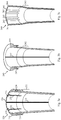
- the invention also depicts a CIC-type receptacle 430 ( Fig. 9 ) - derived from the main embodiment-which, however, requires the liquid-bottling taking place between the walls of the external component-unit 431 and the walls of the intermediate component-unit 432.
- the lateral walls of component-units 432 and 433, connected by interface 434, can move unitarily towards the longitudinal median of a CIC-type receptacle 430 forming a double-walled partitioning-system - each of the walls of the partitioning-system should therefore have a multilayer structure.
- Two storage-compartments 435 are hence formed in the lateral areas of a CIC-type receptacle 430.
- a connecting-system possibly akin to that of a CIC-type receptacle 300 should preferably be present in the mid-section 436 of said CIC-type receptacle 430.
- the lateral walls of the intermediate component-unit 432 secede from those of the internal component-unit 433 and move towards the walls of the external component-unit 431.
- the lateral walls of the intermediate component-unit 432 and those of the internal component-unit 433 may be separated before the cycle-of-use phase.
- atmospheric air may be introduced between the component-units 432 and 433; in this respect, an air-access mechanism (not illustrated) possibly derived from that of a CIC-type receptacle 300 may be used. If present, such air-access mechanism should be suitably adapted, e.g. the flexible circular flap and, equally, the flange closing the enclosure containing the flexible circular flap, should be produced separately and inserted only after the liquid-bottling process, precisely to allow this said process to occur.
- the invention also features a CIC-type receptacle 440 ( Fig. 10 ) consisting of four component-units.
- the liquids are introduced between the two intermediate component-units 442 and 443.
- the multilayer partitioning-system consists of the lateral walls of the intermediate component-unit 443 and those of the internal component-unit 444; the storage-compartments 447 are formed in the lateral areas.
- the walls of the intermediate component-unit 442 secede from those of the external component-unit 441 and move towards the partitioning-system; the walls of the intermediate component-unit 443 secede from those of the internal component-unit 444 moving towards the lateral exterior walls of the CIC-type receptacle 440.
- an air-access mechanism should be suitably adapted.
- the invention also features a CIC-type receptacle 450 ( Fig. 11 ) consisting of only two component-units, the external component-unit 451 and the internal component-unit 452.
- the walls of the partitioning-system should be obtained by delaminating and repositioning the lateral walls of the internal component-unit 452 (possibly in a manner similar to the configuration of the internal component-unit 360 of a CIC-type receptacle 300).
- a CIC-type receptacle 450 can have several functional variants.
- a CIC-type receptacle 450 offers two lateral storage-compartments 454 with fixed geometry - the walls of the partitioning-system are not mobile; the joint 453 may be present between the walls of the partitioning-system to stiffen the assembly.
- the walls of the partitioning-system may be mobile.
- said walls of the partitioning-system could also act as a compression-system for the storage-compartments 454.
- said walls may return - in step with the consumption of liquids - towards the lateral walls of the external component-unit 451, hence producing the storing capacity decrease of the storage-compartments 454; the joint 453 may be omitted if the latter technical solution is adopted.
- a CIC-type receptacle (not illustrated) - derived from a CIC-type receptacle 450 ( Fig. 11 ) - which may have a single inner storage-compartment formed between the walls of the external and internal component-units; in this case, a connecting-system between those two component-units of such CIC-type receptacle should be, at least in part, omitted, hence facilitating free fluid-communication between the lateral storage areas within the receptacle.
- CIC-type receptacle (not illustrated) which may partially be similar to conventional CIC-type receptacles.
- the said CIC-type receptacle made according to present invention may therefore boast two component-units and a single storage-compartment created inside its internal component-unit.
- such said CIC-type receptacle formed in accordance with present invention should be able to incorporate in its external multilayer structure and also make use of: (i) at least one operational-section and/ or (ii) at least one functional-form, possibly of compliant-mechanism-type, elements described previously in relation to CIC-type receptacle 300.
- Such said CIC-type receptacle formed in accordance with present invention may also incorporate, at least in certain embodiments, a connecting-system between its component-units.
- the said connecting-system may be similar to that of a CIC-type receptacle 300, it may consist of a least one permanent-joint and/ or one residual interface and, additionally, said connecting-system may also be reinforced with dedicated functional-forms.
- CIC-type receptacle (not illustrated) with more than two storage-compartments.
- Such alternative CIC-type receptacle could be made as well out of three component-units - similar to a CIC-type receptacle 300 - but, due to different partitioning, it may have more than two storage-compartments: for example, a storage-compartment may be created between the walls of the partitioning-system.
- a CIC-type receptacle with more than two storage-compartments may also be obtained from a number of component-units other than three. For example, it could be similar to a CIC-type receptacle 440, but with supplementary storage-compartments between the walls of the partitioning-system.
- the storage-compartments may have different volume sizes and/ or may be asymmetrical (variants not illustrated).
- the partitioning-system of a CIC-type receptacle can be positioned on coordinates other than those presented in the main embodiment of the invention.
- the partitioning-system may intersect the longitudinal median of a said CIC-type receptacle.
- CIC-type receptacle similar to a CIC-type receptacle 300 in that it may comprise three component-units, but in contrast it may have storage-compartments communicating with each other.
- the connecting-system between the component-units of such CIC-type receptacle may be a partial one; such CIC-type receptacle may be hence susceptible to store a single type of fluid.
- balancing the internal pressure over the cycle-of-use of a CIC-type receptacle may also be achieved by introducing a pressurized fluid inside dedicated areas of said receptacle (dedicated areas similar to void-spaces 311 of a CIC-type receptacle 300), a solution in particular applicable to a CIC-type receptacle packing pressurized liquids (carbonated beverages etc).
- CIC-type receptacles shown above may be combined to obtain variants of such CIC-type receptacles; the invention does not insist on them additionally, many combinations being evident.
- the following paragraphs provide a least one configuring method for obtaining both a partitioning-system and the storage-compartments within a CIC-type receptacle 300.
- the preconfiguring process takes place at the level of the upper-segment 301 of a CIC-type receptacle 300, by relocating the petaloid protrusions 264 ( Fig. 4a ) - present in the lateral regions of the top end of the internal component-unit 360 - towards the median M.
- the relocation may be performed via mechanical means; grooves 265 are functional-forms acting as folding elements thus facilitating the relocation of petaloid protrusions 264.
- two incipient storage-compartments 310 ( Fig. 4b ) should exist at the level of the upper-segment 301.
- the walls of the component-units 360 and 340 should still be united.
- the third stage it is performed the complete configuring of the partitioning-system 361 and, concurrently, of the storage-compartments 310.
- This process is preferably performed at the same time with the liquid-bottling process.
- the liquid-bottling takes place via the two incipient storage-compartments 310 obtained in the previous stage.
- a delamination process should occur below the level of the upper-segment 301. More precisely, it should occur the suppression of the interface present between the walls of the internal component-unit 360 and those of the intermediate component-unit 340, at least in the side areas appertaining to side-sections 306.
- the lateral walls of the internal component-unit 360 should be relocated, under the pressure exerted by the injected liquids, towards the region of the median M of the CIC-type receptacle 300.
- a double-walled partitioning-system 361 ( Fig. 6a ) should be formed in the region of the median M of the CIC-type receptacle 300.
- two complete, and fully bottled, storage-compartments 310 should emerge between the walls of the partitioning-system 361 and the outer walls of a CIC-type receptacle 300 on the lateral sides of said CIC-type receptacle 300.
- the delamination and relocation of the said walls of the internal component-unit 360 may be actively influenced by the presence in the structure of a CIC-type receptacle 300 of certain elements detailed previously, among which: operational-sections (e.g. 304, 305, 306), functional-forms (e.g. 394, 395, 396, 397), also, possibly, functional-forms of compliant-mechanism-type, plus one or more components of a connecting-system as detailed previously, as well as build-class factors.
- operational-sections e.g. 304, 305, 306
- functional-forms e.g. 394, 395, 396, 397
- compliant-mechanism-type e.g. 394, 395, 396, 397
- a configuring method for a CIC-type receptacle may involve obtaining two incipient storage-compartments by enlarging two initial cavities. Therefore, an alternate CIC-type receptacle 410 ( Fig. 5 ) may have two lateral notches 414 at the top end of the internal component-unit 413.
- the cavities 415 should be formed between the walls of the notches 414 and the walls of the intermediate component-unit 412, as early as the assembly stage of the preform-set from which the said receptacle 410 derives.
- a configuring method for a CIC-type receptacle can combine the two previous solutions.
- a configuring method for a CIC-type receptacle may involve utilizing a CIC-type receptacle (not illustrated) which has no protrusions and/ or notches.
- the two incipient storage-compartments of a said CIC-type receptacle may be formed by using appropriate means, especially but not exclusively mechanical-type means, to push the lateral regions present at the top end of one of the component-units towards the region of the median M of said CIC-type receptacle.
- a configuring method for a CIC-type receptacle 300 may involve configuring the partitioning-system 361 and the storage-compartments 310 prior to liquid-bottling. This prior configuring may also be only a partial one. To perform a prior configuring, either a fluid, or mechanical means, or possibly a combination of methods may be used. In the case of using a fluid, in the two incipient storage-compartments 310 may be introduced, for example but not exclusively, compressed air.
- the interface between the lateral walls of the internal component-unit 360 and the intermediate component-unit 340 should be suppressed; the lateral walls of the internal component-unit 360 should be thus relocated towards median M, hence achieving the partitioning-system 361 and the storage-compartments 310.
- certain mechanical parts e.g. rod-type ones, may be introduced through the incipient storage-compartments 310 to suppress the interface between the internal component-unit 360 and intermediate component-unit 340. These mechanical parts then can be moved towards the median M with the purpose of pushing against the lateral walls of the internal component-unit 360, hence relocating and transforming said walls into a partitioning-system 361.
- the said prior configuring of the storage-compartments 310 may potentially be carried out in continuation of the blow-molding process, while the CIC-type receptacle 300 still is, at least partially, in the mold in which said process was conducted.
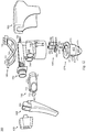
- atomizer 500 compatible with a CIC-type receptacle 300 and apt to simultaneously disperse two liquids. Operation of atomizer 500 is based on principles similar to those of conventional atomizers equipped with hand-operated pumping mechanisms.
- Fig. 12 illustrates the atomizer 500 which is composed of:
- main body 550 there are:
- the valve-system 600 ( Fig. 12 and Fig. 15 ) consists of two valve-subassemblies. Each valve-subassembly consists mainly of a valve 602 ( Fig. 12 ) and an annular seal 601; a bridge 609 connects the annular seal 601 and the valve 602. An additional bridge 610 connects the two valve-subassemblies of the valve-system 600.
- valves 602 are inserted into the housings 561 of the main body 550.
- Each of the valves 602 is composed of:
- the arrangement of the regions 607 ( Fig. 15 ) of the valves 602 dictates - within the main body 550 - the exact location of the perforations 563 which connect the housings 561 and the cylinders 564. Positioning the perforations 563 between the upper edge of the flexible circular flaps 605 and the lower edge of the circular regions 604 enables proper operation of the atomizer.
- annular seals 601 are inserted into the housings 560 ( Fig. 14 and Fig. 15 ). Annular seals 601 serve to seal the openings at the bottom of said housings 560.
- the bridges 609 are inserted into the lower sections of the connecting passages 562 present between the housings 560 and 561.
- the bridges 609 are sealing elements blocking said lower sections of the connecting passages 562.
- the upper sections of said connecting passages 562 remain open even after the bridges 609 are fitted in place, forming between housings 560 and 561 a channel allowing free fluid-communication.
- the bridge 610 reaches in the recess 566 ( Fig. 14 ).
- the liquids are extracted from the storage-compartments 310 of a CIC-type receptacle 300 and transferred inside the housings 560 of the main body 550 via the tubes 655 ( Fig. 15 ).
- the said tubes 655 are part of the closing assembly 650 (the closing assembly will be detailed later).
- the top end of each tube 655 penetrates the corresponding annular seal 601 present at the bottom of the respective housing 560.
- liquids are discharged from the cylinders 564 also by means of perforations 563 into the housings 561.
- the flexible circular flaps 605 force the liquids to stay initially within the housings 561.
- the pressure buildup over a certain level in the housing 561 leads to the partial squashing of the semiflexible crowns 603 of the valves 602; consequently, the circular regions 604 of the semiflexible crowns 603 partially lose contact with the internal surface of the housings 561; the liquids are thus forced to the top end of the housings 561.
- the liquids are transferred through apertures 565 ( Fig. 14 ) in the semicylindrical ducts 570 and 571 ( Fig. 14 and Fig. 15 ). The liquids then progress to the front of the main body 550, reaching the spraying assembly.
- Fig. 16 shows the forepart region of the main body 550 and the spraying nozzle 850, adjacently, with a view of their interior.
- Fig. 17 and Fig. 18 show the same two components, illustrated at the same angle as in Fig. 16 , but from the opposite direction;
- Fig. 17 provides a view of the front region of the spraying nozzle 850;
- Fig. 18 illustrates the forepart region of the main body 550, in a cross sectional perspective from the rear towards the front end.
- a cylindrical region 580 present in the forepart region of the main body 550 ( Fig. 14 ) is continued towards the back end with a frustoconical region 590 ( Fig. 14-15 ).
- the large base of the frustoconical region 590 is open, in continuation of the cylindrical region 580, and the small base is closed.
- Horizontal semicylindrical ducts 571 intersect the frustoconical region 590 ( Fig. 14 and Fig. 15 ); the inner-passageways 573 ( Fig. 18 ) of said horizontal semicylindrical ducts 571 open up inside the frustoconical region 590 in the form of apertures 592 ( Fig. 16 ) practiced on the inner face 591.
- the cylindrical rod member 593 ( Fig. 16 ) is arranged at the center of the closed small base of the frustoconical region 590 and has two longitudinal grooves 594, as well as a swirling chamber 595 on the front.
- the spraying nozzle 850 has some corresponding elements to those present in the forepart region of the main body 550. Owing to assembling, the corresponding elements of the two components of the spraying assembly come into contact: the outer face 852 of the frustoconical region 851 of the spraying nozzle 850 comes into contact with the inner face 591 of the frustoconical region 590; the cylindrical rod member 593 reaches inside the cylindrical conduit 853 of the spraying nozzle 850.
- the spraying nozzle 850 can rotate around the cylindrical rod member 593, having two positions: closed, when liquid spraying is blocked, and open, when spraying is possible. In the closed position, the outer face 852 of the frustoconical region 851 of the spraying nozzle 850 obstructs the apertures 592.
- the slots 854 are communication passages and, in closed position, are spaced out at an angle of 90 degrees relative to longitudinal grooves 594. By rotating the spraying nozzle 850 by 90 degrees, in open position, slots 854 allow communication between apertures 592 and longitudinal grooves 594. The liquids then reach the swirling chamber 595, where they are mixed, and subsequently the liquid mixture is discharged from the atomizer 500 via the orifice 857 ( Fig. 17 ).
- Attaching the atomizer 500 to a CIC-type receptacle 300 is carried out by means of the socket 551 of the main body 550; the projections 553 in the area of the cutouts 552 ( Fig. 14-15 ) - projections oriented towards the inside of the socket - slot into the recesses 231 ( Fig. 4b ) of the upper-segment 301 of a CIC-type receptacle 300.
- the liquid-passageway of each one of the two liquids dispersed by the atomizer 500 can be executed - during the injection molding phase of said main body 550 - such as to result unitary and continuous.
- the inner-passageways of the vertical semicylindrical ducts 570 can be practiced using the apertures 565 ( Fig. 14 ), and those of the horizontal semicylindrical ducts 571 using the apertures 592 ( Fig. 16 ).
- the inner-passageways of the two semicylindrical ducts 570 and 571 may form an angle of 90 degrees and may unite in the region 572 of the main body 550 ( Fig. 15 ).
- the horizontal semicylindrical ducts 571 may be joined via deck 555 ( Fig. 14 and Fig. 15 ), which said deck 555 may be continued at the rear by console 556, which said console 556 in turn may serve as mounting base for the return-spring 700.
- the return-spring 700 ( Fig. 12 ) may be made of acetal/ polyacetal or other types of plastics; the two curved arms 701 store - and subsequently release - an amount of the energy introduced into the system when operating the dispensing system 100 and therefore the atomizer 500.
- the return-spring 700 is secured to the main body 550 via the fixing base 702; the curved arms 701 sit alongside the flanks of the cylinders 564 ( Fig. 13 ); fitting-ends 703 come in contact with the actuation element 800, in the upper lateral areas 802 of the latter.
- the actuation element 800 ( Fig. 12 ) may be attached to the seats 554 of the main body 550 via pins 801 located at its upper extremity.
- the piston-set 750 ( Fig. 12 ) consists of two pistons 751 joined by bridge 752. Owing to assembling, each of the two pistons is inserted in the corresponding cylinder 564 of the main body 550. When under the action of the actuation element 800, the piston-set 750 is moved via projection 753.
- the closing assembly 650 ( Fig. 12 and Fig. 15 ) is part of the atomizer 500 and acts as an intermediate component between the latter and a CIC-type receptacle 300.
- the closing assembly 650 ensures the closure of the storage-compartments 310 of a CIC-type receptacle 300 and, equally, mediates the transfer of liquids from a CIC-type receptacle 300 into an atomizer 500.
- the closing assembly 650 mainly comprises: two stopping members 651; two tubes 655 (already mentioned); two fastening rods 656; flange 658.
- each of the stopping members 651 is inserted in the corresponding storage-compartment 310 of a CIC-type receptacle 300.
- the gap 657 separates the two stopping members 651; the gap 657 represents the place where the upper extremities of the walls of the partitioning-system 361 of a CIC-type receptacle 300 will end up after assembling the dispensing system 100.
- Each of the stopping members 651 consists of a semicylindrical section 652 which is continued downwardly by a petaloid section 653. Owing to assembling, the semicylindrical sections 652 obstruct the storage-compartments 310 in the region of the upper-segment 301 of a CIC-type receptacle 300 ( Fig. 4b ).
- the petaloid sections 653 preferably come to be positioned below the level of the upper-segment 301, thus providing sitting surfaces to the top parts of the walls of the compression-system 341.
- pockets with non-dispersible liquid may develop in those particular areas at the top end of the storage-compartments 310, right below the upper-segments 301, at the end of the cycle-of-use of a CIC-type receptacle 300.
- the tubes 655 allow liquid-extraction from the storage-compartments 310.
- the tubes 655 are connected to the bodies of the stopping members 651, more specifically to the petaloid sections 653.
- the perforations 654 present at the bottom of said tubes 655 penetrate the surface of the petaloid sections 653 ( Fig. 13 and Fig. 15 ).
- the top ends of the tubes 655 may be projected above the level of the flange 658.
- the fastening rods 656 reach the inner recesses of valves 602 - in the base section of said inner recesses - thus additionally securing the valve-system 600.
- the flange 658 acts as a connecting bridge for stopping members 651 and as a base for fastening rods 656.
- the projections 659 ( Fig. 13 and Fig. 15 ) of the flange 658 help to secure the closing assembly 650 to the structure of the main body 550 of the atomizer 500; owing to assembling, the projections 659 reach the upper regions of the cutouts 552 present in the lateral areas of the socket 551 ( Fig. 15 ).
- an atomizer may be fitted with dip tubes to facilitate liquid-extraction from the storage-compartments of a CIC-type receptacle.
- the atomizer can be fitted with such dip tubes for one or more storage-compartments.
- dip tubes may be connected to stopping members 651 by means of perforations 654; the length of those said dip tubes may vary.
- an atomizer capable of dispersing liquids from a CIC-type receptacle with compartments with uneven volumes may have cylinders of different sizes; the corresponding pistons may also have different sizes.
- a dispensing system 100 By combining a CIC-type receptacle 300 and an atomizer 500 is obtained a dispensing system 100.
Landscapes
- Engineering & Computer Science (AREA)
- Mechanical Engineering (AREA)
- Manufacturing & Machinery (AREA)
- Physics & Mathematics (AREA)
- Geometry (AREA)
- Containers And Packaging Bodies Having A Special Means To Remove Contents (AREA)
- Blow-Moulding Or Thermoforming Of Plastics Or The Like (AREA)
Priority Applications (3)
| Application Number | Priority Date | Filing Date | Title |
|---|---|---|---|
| US17/290,132 US20210394213A1 (en) | 2018-10-30 | 2019-10-29 | Multifluid dispensing system and method |
| AU2019383439A AU2019383439A1 (en) | 2018-10-30 | 2019-10-29 | Multifluid dispensing system and method |
| PCT/EP2019/079574 WO2020104151A2 (fr) | 2018-10-30 | 2019-10-29 | Système et procédé de distribution de fluides multiples |
Applications Claiming Priority (3)
| Application Number | Priority Date | Filing Date | Title |
|---|---|---|---|
| ROA201800505A RO132917A0 (ro) | 2018-07-04 | 2018-07-04 | Sisteme dispersoare |
| ROA201800856A RO134317A2 (ro) | 2018-10-30 | 2018-10-30 | Sistem dispersor şi procedeu asociat |
| EP19177450 | 2019-05-29 |
Publications (2)
| Publication Number | Publication Date |
|---|---|
| EP3650126A2 true EP3650126A2 (fr) | 2020-05-13 |
| EP3650126A3 EP3650126A3 (fr) | 2020-08-05 |
Family
ID=67437536
Family Applications (1)
| Application Number | Title | Priority Date | Filing Date |
|---|---|---|---|
| EP19184531.2A Withdrawn EP3650126A3 (fr) | 2018-07-04 | 2019-07-04 | Système de distribution multifluides et procédé associé |
Country Status (1)
| Country | Link |
|---|---|
| EP (1) | EP3650126A3 (fr) |
Cited By (1)
| Publication number | Priority date | Publication date | Assignee | Title |
|---|---|---|---|---|
| WO2022231444A1 (fr) | 2021-04-29 | 2022-11-03 | Icb Pharma Spółka Jawna Tomasz Świętosławski Paweł Świętosławski | Dispositif de distribution pour combiner au moins deux composants séparés d'un système à composants multiples avant une première utilisation et récipient remplaçable apte à être installé dans un tel dispositif de distribution |
Citations (1)
| Publication number | Priority date | Publication date | Assignee | Title |
|---|---|---|---|---|
| WO2009088285A1 (fr) | 2008-01-08 | 2009-07-16 | Dispensing Technologies B.V. | Contenant composite et son procédé de fabrication |
Family Cites Families (4)
| Publication number | Priority date | Publication date | Assignee | Title |
|---|---|---|---|---|
| AU2002343776B2 (en) * | 2001-10-31 | 2008-02-14 | Yoshino Kogyosho Co., Ltd. | Blow-molded container |
| DE102010024980B4 (de) * | 2010-06-24 | 2012-04-26 | Gaplast Gmbh | Behälter mit Innenbeutel |
| JP6011929B2 (ja) * | 2012-10-31 | 2016-10-25 | 株式会社吉野工業所 | 2軸延伸ブロー成形容器及びその製造方法 |
| ES2732942T3 (es) * | 2015-01-23 | 2019-11-26 | Kyoraku Co Ltd | Recipiente deslaminable |
-
2019
- 2019-07-04 EP EP19184531.2A patent/EP3650126A3/fr not_active Withdrawn
Patent Citations (1)
| Publication number | Priority date | Publication date | Assignee | Title |
|---|---|---|---|---|
| WO2009088285A1 (fr) | 2008-01-08 | 2009-07-16 | Dispensing Technologies B.V. | Contenant composite et son procédé de fabrication |
Cited By (2)
| Publication number | Priority date | Publication date | Assignee | Title |
|---|---|---|---|---|
| WO2022231444A1 (fr) | 2021-04-29 | 2022-11-03 | Icb Pharma Spółka Jawna Tomasz Świętosławski Paweł Świętosławski | Dispositif de distribution pour combiner au moins deux composants séparés d'un système à composants multiples avant une première utilisation et récipient remplaçable apte à être installé dans un tel dispositif de distribution |
| US12496601B2 (en) | 2021-04-29 | 2025-12-16 | Icb Pharma Spolka Jawna Tomasz Swietoslawski, Pawel Swietoslawski | Dispensing device for combining at least two separate components of a multi-component system prior to first use and a replaceable container apt to be installed in such a dispensing device |
Also Published As
| Publication number | Publication date |
|---|---|
| EP3650126A3 (fr) | 2020-08-05 |
Similar Documents
| Publication | Publication Date | Title |
|---|---|---|
| EP0710507B1 (fr) | Distributeur pour la distribution simultanée de liquides différents | |
| AU731731B2 (en) | Dual fluid dispenser | |
| US5535950A (en) | Dual trigger sprayer | |
| US5899361A (en) | Hinged closure for a dual chamber dispensing package | |
| US20070164132A1 (en) | Spray nozzle | |
| US7097077B2 (en) | Fluid-dispensing pump and container provided therewith | |
| US20070151987A1 (en) | Deformable flexible pouch and device for packaging and dispensing fluid products | |
| JP2008500173A (ja) | 流体散布器用ポンプ | |
| JP2005512907A (ja) | 流体の包装及び分配用の、硬質容器及び複数の軟質ポケットを有する装置 | |
| US20050184101A1 (en) | Fluid-storing and -dispensing container | |
| KR102633502B1 (ko) | 특히, 액상 대 패스티상 물질용 디스펜서 | |
| US20050269372A1 (en) | Vented dispensing package | |
| EP3650126A2 (fr) | Système de distribution multifluides et procédé associé | |
| US20190161245A1 (en) | Valve for a dispensing container | |
| US20210394213A1 (en) | Multifluid dispensing system and method | |
| KR102170596B1 (ko) | 트리거식 분출기 | |
| EP3730420B1 (fr) | Contenant tubulaire comprenant un tube extérieur et un récipient intérieur | |
| CN101360653B (zh) | 成型容器 | |
| EP3431187B1 (fr) | Dispositif de distribution d'une pluralité de produits fluides | |
| US20240375134A1 (en) | Manually operated pump | |
| CN101795779A (zh) | 液体喷雾分配器 | |
| RO134317A2 (ro) | Sistem dispersor şi procedeu asociat | |
| RO132917A0 (ro) | Sisteme dispersoare | |
| US20040074860A1 (en) | Receptacle having a reinforced wall | |
| US20050061833A1 (en) | Manual pump with integrated components |
Legal Events
| Date | Code | Title | Description |
|---|---|---|---|
| PUAI | Public reference made under article 153(3) epc to a published international application that has entered the european phase |
Free format text: ORIGINAL CODE: 0009012 |
|
| STAA | Information on the status of an ep patent application or granted ep patent |
Free format text: STATUS: THE APPLICATION HAS BEEN PUBLISHED |
|
| AK | Designated contracting states |
Kind code of ref document: A2 Designated state(s): AL AT BE BG CH CY CZ DE DK EE ES FI FR GB GR HR HU IE IS IT LI LT LU LV MC MK MT NL NO PL PT RO RS SE SI SK SM TR |
|
| AX | Request for extension of the european patent |
Extension state: BA ME |
|
| PUAL | Search report despatched |
Free format text: ORIGINAL CODE: 0009013 |
|
| AK | Designated contracting states |
Kind code of ref document: A3 Designated state(s): AL AT BE BG CH CY CZ DE DK EE ES FI FR GB GR HR HU IE IS IT LI LT LU LV MC MK MT NL NO PL PT RO RS SE SI SK SM TR |
|
| AX | Request for extension of the european patent |
Extension state: BA ME |
|
| RIC1 | Information provided on ipc code assigned before grant |
Ipc: B05B 11/00 20060101AFI20200630BHEP Ipc: B29C 49/22 20060101ALI20200630BHEP Ipc: B65D 1/02 20060101ALI20200630BHEP |
|
| STAA | Information on the status of an ep patent application or granted ep patent |
Free format text: STATUS: REQUEST FOR EXAMINATION WAS MADE |
|
| 17P | Request for examination filed |
Effective date: 20210208 |
|
| RBV | Designated contracting states (corrected) |
Designated state(s): AL AT BE BG CH CY CZ DE DK EE ES FI FR GB GR HR HU IE IS IT LI LT LU LV MC MK MT NL NO PL PT RO RS SE SI SK SM TR |
|
| R17P | Request for examination filed (corrected) |
Effective date: 20210205 |
|
| RBV | Designated contracting states (corrected) |
Designated state(s): AL AT BE BG CH CY CZ DE DK EE ES FI FR GB GR HR HU IE IS IT LI LT LU LV MC MK MT NL NO PL PT RO RS SE SI SK SM TR |
|
| STAA | Information on the status of an ep patent application or granted ep patent |
Free format text: STATUS: EXAMINATION IS IN PROGRESS |
|
| 17Q | First examination report despatched |
Effective date: 20230601 |
|
| STAA | Information on the status of an ep patent application or granted ep patent |
Free format text: STATUS: THE APPLICATION IS DEEMED TO BE WITHDRAWN |
|
| 18D | Application deemed to be withdrawn |
Effective date: 20250201 |