EP3650627B1 - Verfahren und vorrichtung zur genauen positionierung eines beweglich angeordneten paneels - Google Patents
Verfahren und vorrichtung zur genauen positionierung eines beweglich angeordneten paneels Download PDFInfo
- Publication number
- EP3650627B1 EP3650627B1 EP18205017.9A EP18205017A EP3650627B1 EP 3650627 B1 EP3650627 B1 EP 3650627B1 EP 18205017 A EP18205017 A EP 18205017A EP 3650627 B1 EP3650627 B1 EP 3650627B1
- Authority
- EP
- European Patent Office
- Prior art keywords
- panel
- moveable panel
- drive motor
- moveable
- braking distance
- Prior art date
- Legal status (The legal status is an assumption and is not a legal conclusion. Google has not performed a legal analysis and makes no representation as to the accuracy of the status listed.)
- Active
Links
Images


Classifications
-
- B—PERFORMING OPERATIONS; TRANSPORTING
- B60—VEHICLES IN GENERAL
- B60J—WINDOWS, WINDSCREENS, NON-FIXED ROOFS, DOORS, OR SIMILAR DEVICES FOR VEHICLES; REMOVABLE EXTERNAL PROTECTIVE COVERINGS SPECIALLY ADAPTED FOR VEHICLES
- B60J7/00—Non-fixed roofs; Roofs with movable panels, e.g. rotary sunroofs
- B60J7/02—Non-fixed roofs; Roofs with movable panels, e.g. rotary sunroofs of sliding type, e.g. comprising guide shoes
- B60J7/04—Non-fixed roofs; Roofs with movable panels, e.g. rotary sunroofs of sliding type, e.g. comprising guide shoes with rigid plate-like element or elements, e.g. open roofs with harmonica-type folding rigid panels
- B60J7/057—Driving or actuating arrangements e.g. manually operated levers or knobs
- B60J7/0573—Driving or actuating arrangements e.g. manually operated levers or knobs power driven arrangements, e.g. electrical
-
- B—PERFORMING OPERATIONS; TRANSPORTING
- B60—VEHICLES IN GENERAL
- B60J—WINDOWS, WINDSCREENS, NON-FIXED ROOFS, DOORS, OR SIMILAR DEVICES FOR VEHICLES; REMOVABLE EXTERNAL PROTECTIVE COVERINGS SPECIALLY ADAPTED FOR VEHICLES
- B60J7/00—Non-fixed roofs; Roofs with movable panels, e.g. rotary sunroofs
- B60J7/02—Non-fixed roofs; Roofs with movable panels, e.g. rotary sunroofs of sliding type, e.g. comprising guide shoes
- B60J7/04—Non-fixed roofs; Roofs with movable panels, e.g. rotary sunroofs of sliding type, e.g. comprising guide shoes with rigid plate-like element or elements, e.g. open roofs with harmonica-type folding rigid panels
- B60J7/043—Sunroofs e.g. sliding above the roof
-
- E—FIXED CONSTRUCTIONS
- E05—LOCKS; KEYS; WINDOW OR DOOR FITTINGS; SAFES
- E05F—DEVICES FOR MOVING WINGS INTO OPEN OR CLOSED POSITION; CHECKS FOR WINGS; WING FITTINGS NOT OTHERWISE PROVIDED FOR, CONCERNED WITH THE FUNCTIONING OF THE WING
- E05F15/00—Power-operated mechanisms for wings
- E05F15/60—Power-operated mechanisms for wings using electrical actuators
- E05F15/603—Power-operated mechanisms for wings using electrical actuators using rotary electromotors
- E05F15/632—Power-operated mechanisms for wings using electrical actuators using rotary electromotors for horizontally-sliding wings
- E05F15/655—Power-operated mechanisms for wings using electrical actuators using rotary electromotors for horizontally-sliding wings specially adapted for vehicle wings
- E05F15/659—Control circuits therefor
-
- G—PHYSICS
- G05—CONTROLLING; REGULATING
- G05D—SYSTEMS FOR CONTROLLING OR REGULATING NON-ELECTRIC VARIABLES
- G05D3/00—Control of position or direction
- G05D3/12—Control of position or direction using feedback
- G05D3/125—Control of position or direction using feedback using discrete position sensor
-
- B—PERFORMING OPERATIONS; TRANSPORTING
- B60—VEHICLES IN GENERAL
- B60J—WINDOWS, WINDSCREENS, NON-FIXED ROOFS, DOORS, OR SIMILAR DEVICES FOR VEHICLES; REMOVABLE EXTERNAL PROTECTIVE COVERINGS SPECIALLY ADAPTED FOR VEHICLES
- B60J7/00—Non-fixed roofs; Roofs with movable panels, e.g. rotary sunroofs
- B60J7/02—Non-fixed roofs; Roofs with movable panels, e.g. rotary sunroofs of sliding type, e.g. comprising guide shoes
- B60J7/04—Non-fixed roofs; Roofs with movable panels, e.g. rotary sunroofs of sliding type, e.g. comprising guide shoes with rigid plate-like element or elements, e.g. open roofs with harmonica-type folding rigid panels
- B60J7/057—Driving or actuating arrangements e.g. manually operated levers or knobs
-
- E—FIXED CONSTRUCTIONS
- E05—LOCKS; KEYS; WINDOW OR DOOR FITTINGS; SAFES
- E05Y—INDEXING SCHEME ASSOCIATED WITH SUBCLASSES E05D AND E05F, RELATING TO CONSTRUCTION ELEMENTS, ELECTRIC CONTROL, POWER SUPPLY, POWER SIGNAL OR TRANSMISSION, USER INTERFACES, MOUNTING OR COUPLING, DETAILS, ACCESSORIES, AUXILIARY OPERATIONS NOT OTHERWISE PROVIDED FOR, APPLICATION THEREOF
- E05Y2400/00—Electronic control; Electrical power; Power supply; Power or signal transmission; User interfaces
- E05Y2400/10—Electronic control
- E05Y2400/32—Position control, detection or monitoring
-
- E—FIXED CONSTRUCTIONS
- E05—LOCKS; KEYS; WINDOW OR DOOR FITTINGS; SAFES
- E05Y—INDEXING SCHEME ASSOCIATED WITH SUBCLASSES E05D AND E05F, RELATING TO CONSTRUCTION ELEMENTS, ELECTRIC CONTROL, POWER SUPPLY, POWER SIGNAL OR TRANSMISSION, USER INTERFACES, MOUNTING OR COUPLING, DETAILS, ACCESSORIES, AUXILIARY OPERATIONS NOT OTHERWISE PROVIDED FOR, APPLICATION THEREOF
- E05Y2400/00—Electronic control; Electrical power; Power supply; Power or signal transmission; User interfaces
- E05Y2400/10—Electronic control
- E05Y2400/32—Position control, detection or monitoring
- E05Y2400/35—Position control, detection or monitoring related to specific positions
- E05Y2400/354—End positions
-
- E—FIXED CONSTRUCTIONS
- E05—LOCKS; KEYS; WINDOW OR DOOR FITTINGS; SAFES
- E05Y—INDEXING SCHEME ASSOCIATED WITH SUBCLASSES E05D AND E05F, RELATING TO CONSTRUCTION ELEMENTS, ELECTRIC CONTROL, POWER SUPPLY, POWER SIGNAL OR TRANSMISSION, USER INTERFACES, MOUNTING OR COUPLING, DETAILS, ACCESSORIES, AUXILIARY OPERATIONS NOT OTHERWISE PROVIDED FOR, APPLICATION THEREOF
- E05Y2400/00—Electronic control; Electrical power; Power supply; Power or signal transmission; User interfaces
- E05Y2400/10—Electronic control
- E05Y2400/40—Control units therefor
-
- E—FIXED CONSTRUCTIONS
- E05—LOCKS; KEYS; WINDOW OR DOOR FITTINGS; SAFES
- E05Y—INDEXING SCHEME ASSOCIATED WITH SUBCLASSES E05D AND E05F, RELATING TO CONSTRUCTION ELEMENTS, ELECTRIC CONTROL, POWER SUPPLY, POWER SIGNAL OR TRANSMISSION, USER INTERFACES, MOUNTING OR COUPLING, DETAILS, ACCESSORIES, AUXILIARY OPERATIONS NOT OTHERWISE PROVIDED FOR, APPLICATION THEREOF
- E05Y2900/00—Application of doors, windows, wings or fittings thereof
- E05Y2900/50—Application of doors, windows, wings or fittings thereof for vehicles
- E05Y2900/53—Type of wing
- E05Y2900/542—Roof panels
Definitions
- the present invention pertains to a method for positioning a movably arranged panel, to a sunroof panel assembly configured to perform such method and to a computer readable medium carrying computer readable instructions for instructing a computer to perform such method.
- a vehicle having a sunroof or a similar panel may be a fixed panel, but the panel may as well be tiltable to a tilt position for ventilation and/or may be slideable to provide for a relatively large opening in a roof of the vehicle.
- Such moveably arranged panels need to be controllable to be moved to a predetermined position.
- the moveable panel should be moveable to a closed position. In the closed position, the moveable panel should be water tight to prevent leakage of rain water, for example.
- the moveable panel is preferably accurately positionable for aesthetic reasons or aerodynamic reasons. Further, e.g. upon closing, it may be preferred to have no noise, like clicking or ticking sounds due to hardware elements colliding, as such sounds are usually not appreciated by users of the vehicle. Similar considerations may apply to moving the moveable panel to any other position.
- the moveable panel When the vehicle is not moving, accurately positioning the moveable panel may be relatively straightforward. However, the moveable panel may be operated under many other conditions. First of all, while driving, aerodynamic air flows are generated around the vehicle. Consequently, the moveable panel may be operated under different air pressures. Moreover, the air pressure may even differ over a trajectory to be travelled by the moveable panel. For example, when moving from an open position, wherein air may flow into the interior of the vehicle, to a closed position, wherein no air can flow into the interior, the air flow and corresponding air pressure on the moveable panel may change during closing operation. Other conditions may affect the moving operation of the moveable panel as well. For example, road conditions, weather conditions, wear over the lifetime of the moveable panel and many other conditions may affect the way the moveable panel moves.
- control unit that operates a drive motor that drives the moveable panel.
- the moveable panel may continue to move, when a drive current to the drive motor is switched off due to inertia of the moveable panel. Therefore, in a known moveable panel assembly, the control unit may switch off the drive motor prematurely such that the inertia may move the moveable panel to the desired position. Then, as soon as the moveable panel has come to standstill, the position of the moveable panel is compared to the desired position and if the moveable panel is not within a predetermined range of the desired position, the control unit corrects the position by operating the drive motor again.
- Such an iterative control loop for final positioning is undesirable as it may prove difficult to control the moveable panel to move only slightly in view of e.g. static friction or play in the mechanical assembly. Moreover, a moveable panel that repeatedly moves before coming to its final position may not be appreciated by users.
- WO98/08148 , DE102012024902 and DE10026991 each disclose a method of controlling a vehicle side window, wherein one or more physical properties are directly or indirectly used to determine a braking distance. Based on the determined braking distance, a drive is stopped when the window has not yet reached a desired stop position. The drive is stopped at a distance from the desired stop position such that the window will stop eventually at the desired position after having moved further over the determined braking distance.
- the above object is achieved in a method according to appended claim 1, wherein the moveable panel is operatively coupled through a drive assembly to a drive motor for moving the moveable panel and the method comprises the steps of actuating the drive motor to move the moveable panel to a desired stop position; determining a panel braking distance based on a physical property of the moveable panel and a physical property of at least one of the drive assembly and the drive motor, wherein the panel braking distance corresponds to a distance covered by the moveable panel in a period of time starting from a decision to switch off the drive motor until stand-still of the moveable panel; determining an actual position of the moveable panel; determining an expected stop position by adding the panel braking distance and the present position; and switching off the drive motor if the expected stop position is within a predetermined range around the desired stop position and repeating the above steps of determining a panel braking distance, determining an actual position and determining an expected stop position, if the expected stop position is outside said predetermined range.
- the panel braking distance is repeatedly determined on the basis of instant conditions and properties.
- the panel braking distance is determined on the basis of at least one physical property of the moveable panel, such as its weight or speed, and at least one physical property of at least one of the drive assembly and the drive motor.
- friction in the drive assembly or friction in the drive motor may be used.
- Most of such physical properties are variable depending on the conditions. For example, friction is dependent on temperature, position of the moveable panel, age of the moveable panel (wear) and other conditions.
- at least some, preferably all, of the physical properties used for determining the panel braking distance are determined instantly such to determine an instant panel braking distance.
- an expected stop position is determined.
- the expected stop position is the position where the moveable panel would come to standstill, if the drive motor would be switched off at that moment. If the expected stop position is not within a predetermined range around the desired stop position, the method returns to determining the panel brake distance again. If the expected stop position is within said predetermined range, the method continues with switching off the drive motor.
- the method is sufficient accurate to reliably stop the moveable panel at or sufficiently near the desired stop position such that no further correction of the final stop position is needed.
- the step of determining the panel braking distance comprises a step of determining a speed of movement of the moveable panel and further comprises at least one of the steps of determining a mechanical braking distance based on said speed, wherein the mechanical braking distance corresponds to a distance travelled by the moveable panel after removing a drive current to the drive motor; and determining a control delay induced braking distance based on said speed, wherein the control-delay-induced distance corresponds to a distance travelled by the moveable panel in a processing period between a decision of a control unit to switch off the drive motor and actual removal of the drive current to the drive motor.
- the panel braking distance may comprise multiple aspects.
- the method is performed by a control unit and the processing period comprises a predetermined processing delay in the control unit.
- the control unit requires a certain software processing time to perform the required operations.
- the drive current is removed by operating a relay and wherein the processing period comprises a predetermined processing delay for switching the relay.
- the relay requires a certain amount of time to switch, during which time the moveable panel travels a certain distance.
- an instant panel friction value is determined for determining the mechanical braking distance, wherein said panel friction value corresponds to friction in the drive assembly.
- friction is dependent on the conditions and is a significant contributor to the resulting mechanical braking distance. Determining the instant panel friction value significantly improves the accuracy of the estimation of the panel braking distance.
- the step of determining the mechanical braking distance comprises taking into account a motor friction value, wherein the motor friction value corresponds to friction induced by the drive motor when no drive current is supplied to the drive motor. Similar to the friction in the drive assembly, the drive motor may exert a significant friction force, when the drive motor is not provided with a drive current. Taking this friction force into account improves the accuracy of the estimation of the panel braking distance.
- the moveable panel is slideable between a first position and a second position, e.g. between a closed position and an open position, wherein the panel braking distance is calculated taking into account an actual slide speed.
- the moveable panel is moveable to a tilt position, wherein the panel braking distance is calculated taking into account an actual tilting speed.
- Known moveable panels may be slideable or tiltable or both.
- the direction of movement of the moveable panel is relevant for determining the inertia-induced mechanical braking distance.
- the sliding movement may be expected to be substantially perpendicular to a direction of gravity
- the tilting movement may be expected to be parallel to a direction of gravity. Therefore, when the moveable panel is in an upward tilting movement, gravity may reduce an inertia-induced braking distance, while in a downward tilting movement, gravity may increase an inertia-induced braking distance. Such effects may be taken into account when determining the panel braking distance.
- a control loop time corresponds to a period of time for performing the steps for determining the panel braking distance, the actual position and the expected stop position.
- the method comprises a further step performed prior to step e.
- Said further step comprises determining said predetermined range based on the control loop time and the actual speed of the moveable panel. Depending on the control loop time, the predetermined range may be determined to be larger or smaller.
- the predetermined range extends between a first range end position and a second range end position and the first range end position is determined based on the control loop time and the actual speed of the moveable panel and the second range end position corresponds to the desired stop position.
- the last step of the method i.e. switching off the drive motor or repeating previous steps, comprises determining a timing for switching off the drive motor if the expected stop position is within the predetermined range. In this embodiment, if the expected stop position is within the predetermined range, the actual moment of switching off the drive motor is selected such that the expected stop position is as close as possible to the desired stop position.
- the predetermined range does not extend beyond the desired stop position and, further, the drive motor is not automatically switched off immediately, but a suitable timing is determined, wherein such timing corresponds as closely as possible to a position of the moveable panel at which position the moveable panel is at the panel braking distance from the desired stop position.
- a suitable timing is determined, wherein such timing corresponds as closely as possible to a position of the moveable panel at which position the moveable panel is at the panel braking distance from the desired stop position.
- the present invention provides a sunroof panel assembly comprising a moveably arranged panel, a drive motor operatively coupled to the moveable panel for moving the moveable panel and a control unit operatively coupled to the drive motor for operating the drive motor, wherein the control unit is configured for performing the method according to the present invention.
- the present invention provides a vehicle comprising the sunroof panel assembly according to the present invention.
- the present invention provides a computer readable medium carrying computer readable instructions for instructing a computer, e.g. a control unit, to perform the method according to the present invention.
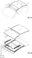
- Fig. 1A illustrates a vehicle roof 1 with a moveable panel 2a and a fixed panel 2b.
- the moveable panel 2a is moveable over a first roof opening 3a.
- a wind deflector 4 is arranged at a front side of the first roof opening 3a.
- the illustrated vehicle roof 1 corresponds to a passenger car.
- the present invention is however not limited to passenger cars. Any other kind of vehicles having a moveable panel are contemplated as well.
- Fig. 1B illustrates the same vehicle roof as Fig. 1A with panels 2a and 2b. Further, in this exploded view of Fig. 1B , it is shown that there is a second roof opening 3b.
- the second roof opening 3b is arranged under the fixed panel 2b such that light may enter a vehicle interior space through the fixed panel 2b, presuming that the fixed panel 2b is a glass panel or a similarly transparent panel, for example made of a plastic material or any other suitable material.
- the wind deflector 4 comprises commonly a flexible material, e.g. a woven or non-woven cloth having through holes arranged therein or a web or net.
- the flexible material is supported by a support structure 4a, e.g. a bar-like or tubelike structure, which structure is hingedly coupled, directly or indirectly, to the vehicle roof 1 at a hinge 4b.
- the wind deflector 4 is arranged in front of the first roof opening 3a and adapts air flow when the moveable panel 2a is in an open position, in particular in a position wherein the moveable panel 2a is slid open and the first roof opening 3a is exposed. In its raised position, the wind deflector 4 reduces inconvenient noise due to air flow during driving.
- the moveable panel 2a When the moveable panel 2a is in a closed position, i.e. a position wherein the moveable panel 2a is arranged over and closes the first roof opening 3a and usually is arranged in a plane of the vehicle roof 1, or in a tilted position, i.e. a position wherein a rear end RE of the moveable panel 2a is raised as compared to the closed position, while a front end FE of the moveable panel 2a is still in the closed position, the wind deflector 4 is held down below the front end FE of the moveable panel 2a.
- a closed position i.e. a position wherein the moveable panel 2a is arranged over and closes the first roof opening 3a and usually is arranged in a plane of the vehicle roof 1, or in a tilted position, i.e. a position wherein a rear end RE of the moveable panel 2a is raised as compared to the closed position, while a front end FE of the moveable panel 2a is still
- the wind deflector 4 is raised by a spring force when the moveable panel 2a slides to an open position and the wind deflector 4 is pushed down by the moveable panel 2a when the moveable panel 2a slides back to its closed position.
- Fig. 1A the moveable panel 2a is shown in an open position and the wind deflector 4 is shown in a raised position.
- Fig. 1B is an exploded view of the moveable panel 2a in a closed position and the wind deflector 4 is correspondingly shown in a position in which it is held down.
- Fig. 1B further illustrates a drive assembly having a first guide assembly 5, a second guide assembly 6, a first drive cable 7 and a second drive cable 8.
- Each guide assembly 5, 6 commonly comprises a guide and a mechanism, wherein the mechanism is slidably moveable in the guide.
- the first and second guide assemblies 5, 6 are arranged on respective side ends SE of the moveable panel 2a.
- the first and the second drive cables 7, 8 are provided between the respective guide assemblies 5, 6 and a drive motor 9.
- the drive cables 7, 8 couple the drive motor 9 to the mechanism of the respective guide assemblies 5, 6 such that upon operating the drive motor 9, the mechanism of each guide assembly 5, 6 starts to move.
- a core of the drive cable 7, 8 is moved by the drive motor 9 such to push or pull on the mechanism of the respective guide assemblies 5, 6.
- a drive assembly is well known in the art and is therefore not further elucidated herein.
- any other suitable drive assembly may be employed as well without departing from the scope of the present invention as defined by the appended claims.
- a drive motor may be operatively coupled between the respective guides and mechanisms of the guide assemblies 5, 6 and the illustrated drive assembly with drive cables 7, 8 may then be omitted completely.
- the mechanisms of the guide assemblies 5, 6 may start to raise the rear end RE of the moveable panel 2a, thereby bringing the moveable panel 2a in the tilted position. Then, from the tilted position, the guide assemblies 5, 6 may start to slide to bring the moveable panel 2a in the open position.
- the moveable panel 2a may be moveable to a tilted position by raising the rear end RE, while an open position is reached by first lowering the rear end RE and then sliding the moveable panel 2a under the fixed panel 2b or any other structure or element provided behind the rear end RE of the moveable panel 2a.
- the moveable panel 2a may be merely moveable between a closed position and a tilted position or between a closed position and an open position.
- the drive motor 9 is mounted near or below the front end FE of the moveable panel 2a at a recess 10. In another embodiment, the drive motor 9 may be positioned at any other suitable position or location. For example, the drive motor 9 may be arranged near or below the rear end RE of the moveable panel 2a or below the fixed panel 2b.
- a control unit 11 is schematically illustrated and operatively coupled to the drive motor 9.
- the control unit 11 may be any kind of processing unit, either a software controlled processing unit or a dedicated processing unit, like an ASIC, as well known to those skilled in the art.
- the control unit may be a stand-alone control unit or it may be operatively connected to another control unit, like a multipurpose, generic vehicle control unit.
- the control unit 11 may be embedded in or be part of such a vehicle control unit.
- the control unit 11 may be embodied by any control unit suitable for, capable of and configured for performing an embodiment of the method according to the present invention.
- the control unit 11 is adapted and configured to move the moveable panel 2a to such position and stop the moveable panel 2a at such a desired stop position.
- the moveable panel 2a may stop before or after the intended and desired stop position. If the desired stop position corresponds to the closed position, this may result in the moveable panel 2a not closing the roof opening 3a sufficiently, potentially resulting in rain leakage, for example, or the moveable panel 2a may not be level with e.g. the fixed panel 2b resulting in deteriorated aerodynamics and corresponding fuel usage.
- an overshoot in the desired position may result in elements of the guides 5, 6 may collide with each other or other parts resulting in collision sounds that are not appreciated by users.
- An undershoot in the desired position means that the moveable panel 2a is not fully opened, which is of course also not appreciated by a user. Therefore, the control unit 11 may be provided with a method to more accurately achieve that the moveable panel 2a stops at the desired position.
- a prior art method is illustrated, wherein the method is configured to achieve a more accurate positioning of the moveable panel.
- the control unit monitors the position of the moveable panel in step S202.
- the position may be monitored using suitable dedicated position measurement techniques and corresponding means. For example, an encoder may be applied or an ultrasonic technique may be applied.
- rotations of the drive motor are monitored and based on those rotations the position of the moveable panel is derived.
- a braking distance is determined.
- the braking distance is a distance that the moveable panel travels after the drive motor is switched off. For example, as known in the art, inertia will result in the moveable panel moving further before coming to a halt after the drive motor is switched off.
- the braking distance is determined by using the moveable panel weight and a moving speed of the moveable panel, wherein the speed may be an actual speed or an intended speed. Presuming a constant brake force, a simple inertia calculation is used to determine the braking distance.
- a braking distance is determined in an initial calibration method, e.g. directly after manufacturing or directly after mounting in the vehicle roof. Presuming a constant braking distance, the braking distance is stored as a static value and is retrieved from memory in step S203.
- step S204 it is checked whether the moveable panel has reached the brake position. If the moveable panel has not yet reached the brake position, the method returns to step S202. Of course, depending on the embodiment of the step S203, step S203 may be repeated or not. In the illustrated prior art embodiment, the braking distance is determined again.
- step S204 If it is determined in step S204 that the brake position is reached, the drive motor is switched of in step S205. Then, in step S206, the actual stop position of the moveable panel is compared to the desired stop position. In particular, it may be verified whether a deviation from the desired stop position is within an accepted, predetermined tolerance range. Such tolerance range may be selected or determined on the basis of many different aspects as apparent to those skilled in the art. In any case, a small tolerance range may result in more corrective movements.
- step S208 If the actual stop position is within the accepted tolerance range, the method ends at step S208. However, if the actual stop position is outside the accepted tolerance range, the method continues with step S207, wherein the drive motor is re-activated corresponding to a desired corrective movement and the method starts repeating steps S202 - S206.
- the braking force may vary considerably.
- the braking force exerted on the moveable panel may be expected to be considerably different when the moveable panel is sliding from the closed position and the wind deflector is pushing against the moveable panel in its direction of movement.
- the wind deflector will push against the moveable panel in a direction opposite to the direction movement, thereby providing a significantly higher braking force.
- closer to the open position the wind deflector does not contact the moveable panel at all and thus does not provide any force either.
- a temperature affects the friction acting on the moveable panel. So, when driving in summer under the sun, the friction will be significantly different compared to driving in winter in the snow. Further, road conditions may provide for vibrations affecting a smooth travel of the moveable panel. Wear of the mechanical assembly may eventually also affect the friction and hence the braking force. Many other aspects may affect the braking force as well. In any case, the illustrated prior art method will regularly result in corrective movements of the moveable panel which may appear strange to a user and is therefore undesirable.
- Fig. 3 and 4 illustrate an embodiment of a positioning method in accordance with the present invention.
- the moveable panel Upon start S301, the moveable panel is brought into motion and its position is monitored in step S302.
- many different techniques and means may be applied for monitoring the position.
- the present invention is not limited to any specific technique or means for monitoring the position.
- Steps S303, S304 and S305 are performed in accordance with the present invention.
- at least one property of the moving moveable panel is determined.
- a weight of the moveable panel and an actual speed of the moveable panel may be determined in order to derive the momentum of the moving moveable panel.
- at least one property of the drive assembly and/or the drive motor is determined.
- Such a property may be a directly relevant property, such as a friction force, for example.
- it may as well be an indirectly relevant property on the basis of which a relevant property may be derived, such as a material temperature from which an actual friction force may be derivable. In such embodiment, as many indirectly relevant properties may be taken into account in order to arrive at a high positioning accuracy.
- the braking force may be considered to comprise a panel friction force and a motor friction force.
- An instant panel friction force value may be derived during motion from an actual speed and a drive current.
- the drive current is an electrical current supplied to the drive motor and determines a generated torque. Through the actual torque and the actual speed, the instant panel friction force may be calculated. It is noted that this calculation is known for use in detecting an obstruction. If the moveable panel is obstructed, the drive current will increase in order to increase the generated torque such to overcome the force exerted by the obstruction.
- the motor friction force is a force that results when the drive current is removed, while due to inertia the moveable panel pulls on the drive cables and thus attempts to rotate a rotary motor shaft.
- the drive motor however resists due to electrical properties, as well known in the art, resulting in a counterforce.
- This counterforce is considered herein as a motor friction force.
- the motor friction force value may be dependent on the speed of the moving moveable panel.
- the method may then continue with step S309 and using the mechanical braking distance as the (total) braking distance. In another embodiment, however, further aspects affecting the braking distance may be taken into account.
- a software switching delay is taken into account in step S306.
- a certain processing time is needed. During this processing time, the moveable panel is moving.
- a relay switching delay occurs, which relay switching delay is determined in step S307. Likewise, during this relay switching delay the moveable panel is moving.
- step S308 On the basis of the delays determined in steps S306 and S307 and on the basis of the actual speed, which is determined in step S303.
- a control delay induced braking distance which is determined in step S308 on the basis of the delays determined in steps S306 and S307 and on the basis of the actual speed, which is determined in step S303.
- any other delays may be taken into account in this step S308 as well.
- a (total) braking distance is determined in step S309.
- a next step S310 the braking distance is added to the actual position as determined in step S302.
- the position may as well be determined in this step S310 or directly preceding this step S310 instead of step S302 or in addition to step S302.
- the sum of the actual position and the braking distance provides an expected stop position, which is the position at which the moveable panel may be expected to come to a halt if it is decided, at that moment, to switch off the drive motor.
- step S311 the expected stop position is compared to the desired stop position and, in particular, it is determined whether the expected stop position is within a predetermined tolerance range relative to the desired stop position.
- step S302 If the expected stop position is outside the predetermined range, the method continues with step S302.
- the relevant properties are determined again such to have all the actual, instant values available to ensure an accurate determination of the braking distance. These method steps are repeated until it is determined in step S311 that the expected stop position is within the predetermined range.
- step S312 If the expected stop position is within the predetermined range, the method continues with step S312 and the drive motor is switched off.
- the moveable panel will come to a halt at or very close to the desired stop position. No further verification of the actual stop position is required and there is no need to repeat any steps.
- the moveable panel is positioned and stopped without further corrective movements.
- a predetermined tolerance range may be selected arbitrarily or on the basis of specific considerations and/or technical aspects.
- selecting a very small tolerance range many or even an unlimited number of corrective movements will be performed in an attempt to position the moveable panel within the predetermined range. Due to the omission of the loop after stopping the moveable panel, such repeating movements are prevented. Still, selection of a very small tolerance range could proof unwise.
- step S310 is replaced by steps S410-1 - S410-3.
- step S410-1 a loop delay is determined.
- the loop delay is the time needed for repeating the loop comprising the method steps S302 - S309. Similar to the control delay induced braking distance, a loop delay distance is determined in step S410-2 by taking into account the actual speed of the moveable panel.
- step S410-3 the loop delay distance is used to establish an expected stop range, which corresponds to a range starting with the expected stop position as defined in step S310 and ending at an end position, which corresponds to the loop delay distance added to the expected stop position.
- the expected stop range corresponds to the trajectory that is expected to be travelled by the moveable panel if the above-mentioned loop is going to be performed. In other words, it is expected that the moveable panel will be at the above-mentioned end position when all the method steps in said loop have been performed.
- step S411 the expected stop range determined in step S410-3 is compared with the predetermined range. If there is sufficient overlap, in particular if the desired stop position is within the expected stop range, it is decided to continue with step S412-1. Otherwise, if there is no or insufficient overlap, i.e. said loop may be run again without overshooting the desired stop position, the method returns to step S302.
- a switch timing is determined.
- the switch timing corresponds to a timing at which it is expected that the moveable panel will halt at the desired stop position. So, as compared to the embodiment of Fig. 3 , in this embodiment, the switching operation is not necessarily performed immediately, but may be postponed. Of course, in another embodiment, instead of mere timing, an actual position and a switch position may be used to determine an optimal switch timing.
- steps S412-2 is performed by switching off the drive motor.
- the terms and phrases used herein are not intended to be limiting, but rather to provide an understandable description of the invention.
- the terms "a” or “an”, as used herein, are defined as one or more than one.
- the term plurality, as used herein, is defined as two or more than two.
- the term another, as used herein, is defined as at least a second or more.
- the terms including and/or having, as used herein, are defined as comprising (i.e., open language).
- the term coupled, as used herein, is defined as connected, although not necessarily directly.
Landscapes
- Engineering & Computer Science (AREA)
- Mechanical Engineering (AREA)
- Physics & Mathematics (AREA)
- General Physics & Mathematics (AREA)
- Automation & Control Theory (AREA)
- Power-Operated Mechanisms For Wings (AREA)
Claims (12)
- Verfahren zum Positionieren eines bewegbar angeordneten Paneels (2a), wobei das bewegbare Paneel durch eine Antriebseinrichtung mit einem Antriebsmotor (9) zum Bewegen des bewegbaren Paneels betriebsverbunden ist, wobei das Verfahren aufweist die Schrittea. Betätigen (S301) des Antriebsmotors, um das bewegbare Paneel in eine gewünschte Stopp-Position zu bewegen,b. Ermitteln (S309) einer Paneel-Bremsdistanz basierend auf einer physikalischen Eigenschaft des bewegbaren Paneels und einer physikalischen Eigenschaft von wenigstens einem von der Antriebseinrichtung und dem Antriebsmotor, wobei die Paneel-Bremsdistanz zu einer Distanz korrespondiert, die von dem bewegbaren Paneel abgedeckt wird in einer Zeitperiode ausgehend von einer Entscheidung, den Antriebsmotor auszuschalten, bis zum Stillstand des bewegbaren Paneels,c. Ermitteln (S302) einer aktuellen Position des bewegbaren Paneels,d. Ermitteln (S310) einer erwarteten Stopp-Position durch Addieren der Paneel-Bremsdistanz und der gegenwärtigen Position, unde. Ausschalten (S312) des Antriebsmotors, wenn die erwartete Stopp-Position innerhalb eines vorbestimmten Bereichs um die erwartete Stopp-Position herum ist, und Wiederholen der Schritte b, c und d, wenn die erwartete Stopp-Position außerhalb des vorbestimmten Bereichs ist, unddadurch gekennzeichnet, dass
eine Steuerschleifenzeit korrespondiert zu einer Zeitperiode zum Durchführen der Schritte b, c und d, und wobei das Verfahren aufweist einen weiteren Schritt f, der vor dem Schritt e durchgeführt wird, des Ermittelns des vorbestimmten Bereichs basierend auf der Steuerschleifenzeit und der momentanen Geschwindigkeit des bewegbaren Paneels. - Verfahren gemäß Anspruch 1, wobei der Schritt b aufweist einen Schritt
b1. des Ermittelns einer Bewegungsgeschwindigkeit des bewegbaren Paneels,
und ferner aufweist wenigstens einen von den Schritten:b2. Ermitteln (S305) einer mechanischen Bremsdistanz basierend auf der Geschwindigkeit, wobei die mechanische Bremsdistanz zu einer Distanz korrespondiert, die von dem bewegbaren Paneel zurückgelegt wird nach dem Wegnehmen eines Antriebsstroms zu dem Antriebsmotor, undb3. Ermitteln (S308) einer Steuerverzögerung-induzierten-Bremsdistanz basierend auf der Geschwindigkeit, wobei die Steuerverzögerung-induzierte-Distanz zu einer Distanz korrespondiert, die von dem bewegbaren Paneel zurückgelegt wird in einer Verarbeitungsperiode zwischen einer Entscheidung, den Antriebsmotor auszuschalten, und dem tatsächlichen Wegnehmen des Antriebsstroms zu dem Antriebsmotor. - Verfahren gemäß Anspruch 2, wobei das Verfahren von einer Steuereinheit (11) durchgeführt wird und die Verarbeitungsperiode eine vorbestimmte Verarbeitungsverzögerung in der Steuereinheit aufweist.
- Verfahren gemäß Anspruch 2, wobei der Antriebsstrom weggenommen wird durch Betätigen eines Relais und wobei die Verarbeitungsperiode eine vorbestimmte Verarbeitungsverzögerung zum Schalten des Relais aufweist.
- Verfahren gemäß Anspruch 2, wobei der Schritt b2 aufweist Ermitteln eines momentanen Paneel-Reibwerts, wobei der Reibwert zu einer Reibung in einer Antriebseinrichtung korrespondiert, welche Antriebseinrichtung das bewegbare Paneel und den Antriebsmotor mechanisch verbindet.
- Verfahren gemäß Anspruch 2, wobei der Schritt b2 aufweist Berücksichtigen eines Motor-Reibwerts, wobei der Motor-Reibwert zu einer Reibung korrespondiert, die von dem Antriebsmotor induziert wird, wenn kein Antriebsstrom zu dem Antriebsmotor zugeführt wird.
- Verfahren gemäß Anspruch 1, wobei das bewegbare Paneel verschiebbar ist zwischen einer ersten Position und einer zweiten Position, wobei die Paneel-Bremsdistanz berechnet wird unter Berücksichtigung einer aktuellen Verschiebegeschwindigkeit.
- Verfahren gemäß Anspruch 1, wobei das bewegbare Paneel in eine Kipp-Position bewegbar ist, wobei die Paneel-Bremsdistanz berechnet wird unter Berücksichtigung einer aktuellen Kippgeschwindigkeit.
- Verfahren gemäß Anspruch 1, wobei der vorbestimmte Bereich sich erstreckt zwischen einer ersten Bereichsendposition und einer zweiten Bereichsendposition, und wobei die erste Bereichsendposition ermittelt wird basierend auf der Steuerschleifenzeit und der momentanen Geschwindigkeit des bewegbaren Paneels, und wobei die zweite Bereichsendposition zu der gewünschten Stopp-Position korrespondiert, und
wobei der Schritt e aufweist Ermitteln eines Zeitpunkts zum Ausschalten des Antriebsmotors, wenn die erwartete Stopp-Position innerhalb des vorbestimmten Bereichs ist. - Schiebedachpaneel-Einrichtung, aufweisend ein bewegbar angeordnetes Paneel (2a), einen Antriebsmotor (9), der mit dem bewegbaren Paneel betriebsverbunden ist zum Bewegen des bewegbaren Paneels, und eine Steuereinheit (11), die mit dem Antriebsmotor betriebsverbunden ist zum Betätigen des Antriebsmotors, wobei die Steuereinheit konfiguriert ist zum Durchführen des Verfahrens gemäß Anspruch 1.
- Fahrzeug aufweisend die Schiebedachpaneel-Einrichtung gemäß Anspruch 10.
- Computerlesbares Medium, das computerlesbare Instruktionen zum Instruieren eines Computers zum Durchführen der Verfahrensschritte von Anspruch 1 trägt.
Priority Applications (3)
| Application Number | Priority Date | Filing Date | Title |
|---|---|---|---|
| EP18205017.9A EP3650627B1 (de) | 2018-11-07 | 2018-11-07 | Verfahren und vorrichtung zur genauen positionierung eines beweglich angeordneten paneels |
| CN201910889609.1A CN111152638B (zh) | 2018-11-07 | 2019-09-20 | 用于可动地布置的面板的精确定位的方法和装置 |
| US16/673,399 US11479093B2 (en) | 2018-11-07 | 2019-11-04 | Method and device for accurate positioning of a moveably arranged panel |
Applications Claiming Priority (1)
| Application Number | Priority Date | Filing Date | Title |
|---|---|---|---|
| EP18205017.9A EP3650627B1 (de) | 2018-11-07 | 2018-11-07 | Verfahren und vorrichtung zur genauen positionierung eines beweglich angeordneten paneels |
Publications (2)
| Publication Number | Publication Date |
|---|---|
| EP3650627A1 EP3650627A1 (de) | 2020-05-13 |
| EP3650627B1 true EP3650627B1 (de) | 2024-07-17 |
Family
ID=64316285
Family Applications (1)
| Application Number | Title | Priority Date | Filing Date |
|---|---|---|---|
| EP18205017.9A Active EP3650627B1 (de) | 2018-11-07 | 2018-11-07 | Verfahren und vorrichtung zur genauen positionierung eines beweglich angeordneten paneels |
Country Status (3)
| Country | Link |
|---|---|
| US (1) | US11479093B2 (de) |
| EP (1) | EP3650627B1 (de) |
| CN (1) | CN111152638B (de) |
Family Cites Families (11)
| Publication number | Priority date | Publication date | Assignee | Title |
|---|---|---|---|---|
| DE19632910C2 (de) * | 1996-08-16 | 2002-07-25 | Brose Fahrzeugteile | Verfahren zum berührungslosen Anfahren der unteren Anschlagsposition einer fremdkraftbetätigten Fensterscheibe eines Kraftfahrzeugs |
| JP3431439B2 (ja) * | 1997-03-06 | 2003-07-28 | 株式会社日立製作所 | 絶縁開閉装置 |
| DE10026991A1 (de) * | 2000-05-31 | 2001-12-13 | Bosch Gmbh Robert | Verfahren zur Positionierung einer fremdkraftbetätigten Schliessfläche |
| JP4834384B2 (ja) * | 2005-11-15 | 2011-12-14 | アイシン精機株式会社 | 車両ドア制御方法および車両ドア制御システム |
| US7500711B1 (en) * | 2007-08-24 | 2009-03-10 | Ford Global Technologies, Llc | Power door for a passenger vehicle |
| JP4596079B2 (ja) * | 2009-06-25 | 2010-12-08 | アイシン精機株式会社 | 開口覆材の開閉制御装置 |
| US8807644B2 (en) * | 2011-09-29 | 2014-08-19 | Tesla Motors, Inc. | Sunroof positioning and timing elements |
| JP2013170395A (ja) * | 2012-02-21 | 2013-09-02 | Aisin Seiki Co Ltd | 車両用開閉体制御装置 |
| JP5924027B2 (ja) * | 2012-02-29 | 2016-05-25 | アイシン精機株式会社 | 車両用開閉体制御装置 |
| DE102012024902A1 (de) | 2012-12-20 | 2014-06-26 | Brose Fahrzeugteile Gmbh & Co. Kommanditgesellschaft, Hallstadt | Stellvorrichtung zur Verstellung eines beweglichen Fahrzeugteils und Verfahren zum Betrieb derselben |
| JP6303212B2 (ja) * | 2013-10-08 | 2018-04-04 | 三井金属アクト株式会社 | 車両用ドアの開閉制御装置 |
-
2018
- 2018-11-07 EP EP18205017.9A patent/EP3650627B1/de active Active
-
2019
- 2019-09-20 CN CN201910889609.1A patent/CN111152638B/zh active Active
- 2019-11-04 US US16/673,399 patent/US11479093B2/en active Active
Also Published As
| Publication number | Publication date |
|---|---|
| US20200139797A1 (en) | 2020-05-07 |
| CN111152638A (zh) | 2020-05-15 |
| EP3650627A1 (de) | 2020-05-13 |
| CN111152638B (zh) | 2024-03-22 |
| US11479093B2 (en) | 2022-10-25 |
Similar Documents
| Publication | Publication Date | Title |
|---|---|---|
| EP1726763B1 (de) | Kraftfahrzeugtür mit Kurzhubabsenkung der Fensterscheibe | |
| EP3795395B1 (de) | Stützmechanismus für eine offendachanordnung in einem fahrzeugdach | |
| CN114845893A (zh) | 包括具有两个运动单元的车顶打开系统的车顶 | |
| EP3650627B1 (de) | Verfahren und vorrichtung zur genauen positionierung eines beweglich angeordneten paneels | |
| EP2105333B1 (de) | Dachanordnung für ein Fahrzeug und Verfahren zum Betreiben davon | |
| EP0754583A1 (de) | Schiebehebedach und ein mit einem solchen Schiebehebedach ausgerüstetes Kraftfahrzeug | |
| US11577589B2 (en) | Open roof assembly for use in a vehicle and a method for operating same | |
| US11585142B2 (en) | Open roof assembly for use in a vehicle and a method for operating same | |
| JP2002178767A (ja) | 車両用サンルーフの制御装置 | |
| EP4043681A1 (de) | Einklemmerkennungssystem | |
| EP3822102B1 (de) | Verfahren und motorsteuerungssystem zur verwendung in einer fahrzeugdachanordnung | |
| EP4379179A1 (de) | Einklemmdetektionssystem | |
| EP3838639A1 (de) | Offene dachanordnung zur verwendung in einem fahrzeug und verfahren zu deren betrieb | |
| US20090284203A1 (en) | Method for controlling an opening leaf of a vehicle with an anti-trap function | |
| KR100527139B1 (ko) | 자동차용 디플렉터의 지지구조 | |
| CN219806689U (zh) | 开放式车顶组件、引导组件和包括该开放式车顶组件的车辆 | |
| JP5989497B2 (ja) | 窓部開閉検知機構と自動車用スライドドア | |
| CN111546862B (zh) | 一种敞开式车顶组件 | |
| CN117686193A (zh) | 一种用于汽车滑移门铰链的开闭耐久实验工装 | |
| JP2000247150A (ja) | 昇降自在のウインドデフレクタを含む開閉自在な車両ルーフ | |
| CN119527179A (zh) | 用于传感器的车辆车顶模块 | |
| JPH06239144A (ja) | サンルーフ装置の開閉駆動機構 | |
| JPH09142152A (ja) | 車両用サンルーフのガイド装置 | |
| KR20050099315A (ko) | 차량의 슬라이딩 도어 후방측 윈도우의 안전개폐장치 |
Legal Events
| Date | Code | Title | Description |
|---|---|---|---|
| PUAI | Public reference made under article 153(3) epc to a published international application that has entered the european phase |
Free format text: ORIGINAL CODE: 0009012 |
|
| STAA | Information on the status of an ep patent application or granted ep patent |
Free format text: STATUS: THE APPLICATION HAS BEEN PUBLISHED |
|
| AK | Designated contracting states |
Kind code of ref document: A1 Designated state(s): AL AT BE BG CH CY CZ DE DK EE ES FI FR GB GR HR HU IE IS IT LI LT LU LV MC MK MT NL NO PL PT RO RS SE SI SK SM TR |
|
| AX | Request for extension of the european patent |
Extension state: BA ME |
|
| STAA | Information on the status of an ep patent application or granted ep patent |
Free format text: STATUS: REQUEST FOR EXAMINATION WAS MADE |
|
| 17P | Request for examination filed |
Effective date: 20201103 |
|
| RBV | Designated contracting states (corrected) |
Designated state(s): AL AT BE BG CH CY CZ DE DK EE ES FI FR GB GR HR HU IE IS IT LI LT LU LV MC MK MT NL NO PL PT RO RS SE SI SK SM TR |
|
| STAA | Information on the status of an ep patent application or granted ep patent |
Free format text: STATUS: EXAMINATION IS IN PROGRESS |
|
| 17Q | First examination report despatched |
Effective date: 20210617 |
|
| GRAP | Despatch of communication of intention to grant a patent |
Free format text: ORIGINAL CODE: EPIDOSNIGR1 |
|
| STAA | Information on the status of an ep patent application or granted ep patent |
Free format text: STATUS: GRANT OF PATENT IS INTENDED |
|
| INTG | Intention to grant announced |
Effective date: 20240327 |
|
| GRAS | Grant fee paid |
Free format text: ORIGINAL CODE: EPIDOSNIGR3 |
|
| GRAA | (expected) grant |
Free format text: ORIGINAL CODE: 0009210 |
|
| STAA | Information on the status of an ep patent application or granted ep patent |
Free format text: STATUS: THE PATENT HAS BEEN GRANTED |
|
| AK | Designated contracting states |
Kind code of ref document: B1 Designated state(s): AL AT BE BG CH CY CZ DE DK EE ES FI FR GB GR HR HU IE IS IT LI LT LU LV MC MK MT NL NO PL PT RO RS SE SI SK SM TR |
|
| REG | Reference to a national code |
Ref country code: CH Ref legal event code: EP |
|
| REG | Reference to a national code |
Ref country code: DE Ref legal event code: R096 Ref document number: 602018071806 Country of ref document: DE |
|
| REG | Reference to a national code |
Ref country code: IE Ref legal event code: FG4D |
|
| REG | Reference to a national code |
Ref country code: LT Ref legal event code: MG9D |
|
| REG | Reference to a national code |
Ref country code: NL Ref legal event code: MP Effective date: 20240717 |
|
| PG25 | Lapsed in a contracting state [announced via postgrant information from national office to epo] |
Ref country code: PT Free format text: LAPSE BECAUSE OF FAILURE TO SUBMIT A TRANSLATION OF THE DESCRIPTION OR TO PAY THE FEE WITHIN THE PRESCRIBED TIME-LIMIT Effective date: 20241118 |
|
| REG | Reference to a national code |
Ref country code: AT Ref legal event code: MK05 Ref document number: 1704304 Country of ref document: AT Kind code of ref document: T Effective date: 20240717 |
|
| PG25 | Lapsed in a contracting state [announced via postgrant information from national office to epo] |
Ref country code: NL Free format text: LAPSE BECAUSE OF FAILURE TO SUBMIT A TRANSLATION OF THE DESCRIPTION OR TO PAY THE FEE WITHIN THE PRESCRIBED TIME-LIMIT Effective date: 20240717 |
|
| PG25 | Lapsed in a contracting state [announced via postgrant information from national office to epo] |
Ref country code: PT Free format text: LAPSE BECAUSE OF FAILURE TO SUBMIT A TRANSLATION OF THE DESCRIPTION OR TO PAY THE FEE WITHIN THE PRESCRIBED TIME-LIMIT Effective date: 20241118 Ref country code: NL Free format text: LAPSE BECAUSE OF FAILURE TO SUBMIT A TRANSLATION OF THE DESCRIPTION OR TO PAY THE FEE WITHIN THE PRESCRIBED TIME-LIMIT Effective date: 20240717 |
|
| PG25 | Lapsed in a contracting state [announced via postgrant information from national office to epo] |
Ref country code: NO Free format text: LAPSE BECAUSE OF FAILURE TO SUBMIT A TRANSLATION OF THE DESCRIPTION OR TO PAY THE FEE WITHIN THE PRESCRIBED TIME-LIMIT Effective date: 20241017 |
|
| PG25 | Lapsed in a contracting state [announced via postgrant information from national office to epo] |
Ref country code: GR Free format text: LAPSE BECAUSE OF FAILURE TO SUBMIT A TRANSLATION OF THE DESCRIPTION OR TO PAY THE FEE WITHIN THE PRESCRIBED TIME-LIMIT Effective date: 20241018 Ref country code: FI Free format text: LAPSE BECAUSE OF FAILURE TO SUBMIT A TRANSLATION OF THE DESCRIPTION OR TO PAY THE FEE WITHIN THE PRESCRIBED TIME-LIMIT Effective date: 20240717 Ref country code: PL Free format text: LAPSE BECAUSE OF FAILURE TO SUBMIT A TRANSLATION OF THE DESCRIPTION OR TO PAY THE FEE WITHIN THE PRESCRIBED TIME-LIMIT Effective date: 20240717 |
|
| PG25 | Lapsed in a contracting state [announced via postgrant information from national office to epo] |
Ref country code: BG Free format text: LAPSE BECAUSE OF FAILURE TO SUBMIT A TRANSLATION OF THE DESCRIPTION OR TO PAY THE FEE WITHIN THE PRESCRIBED TIME-LIMIT Effective date: 20240717 |
|
| PG25 | Lapsed in a contracting state [announced via postgrant information from national office to epo] |
Ref country code: LV Free format text: LAPSE BECAUSE OF FAILURE TO SUBMIT A TRANSLATION OF THE DESCRIPTION OR TO PAY THE FEE WITHIN THE PRESCRIBED TIME-LIMIT Effective date: 20240717 |
|
| PG25 | Lapsed in a contracting state [announced via postgrant information from national office to epo] |
Ref country code: IS Free format text: LAPSE BECAUSE OF FAILURE TO SUBMIT A TRANSLATION OF THE DESCRIPTION OR TO PAY THE FEE WITHIN THE PRESCRIBED TIME-LIMIT Effective date: 20241117 Ref country code: AT Free format text: LAPSE BECAUSE OF FAILURE TO SUBMIT A TRANSLATION OF THE DESCRIPTION OR TO PAY THE FEE WITHIN THE PRESCRIBED TIME-LIMIT Effective date: 20240717 |
|
| PG25 | Lapsed in a contracting state [announced via postgrant information from national office to epo] |
Ref country code: HR Free format text: LAPSE BECAUSE OF FAILURE TO SUBMIT A TRANSLATION OF THE DESCRIPTION OR TO PAY THE FEE WITHIN THE PRESCRIBED TIME-LIMIT Effective date: 20240717 |
|
| PG25 | Lapsed in a contracting state [announced via postgrant information from national office to epo] |
Ref country code: RS Free format text: LAPSE BECAUSE OF FAILURE TO SUBMIT A TRANSLATION OF THE DESCRIPTION OR TO PAY THE FEE WITHIN THE PRESCRIBED TIME-LIMIT Effective date: 20241017 Ref country code: ES Free format text: LAPSE BECAUSE OF FAILURE TO SUBMIT A TRANSLATION OF THE DESCRIPTION OR TO PAY THE FEE WITHIN THE PRESCRIBED TIME-LIMIT Effective date: 20240717 |
|
| PG25 | Lapsed in a contracting state [announced via postgrant information from national office to epo] |
Ref country code: RS Free format text: LAPSE BECAUSE OF FAILURE TO SUBMIT A TRANSLATION OF THE DESCRIPTION OR TO PAY THE FEE WITHIN THE PRESCRIBED TIME-LIMIT Effective date: 20241017 Ref country code: PL Free format text: LAPSE BECAUSE OF FAILURE TO SUBMIT A TRANSLATION OF THE DESCRIPTION OR TO PAY THE FEE WITHIN THE PRESCRIBED TIME-LIMIT Effective date: 20240717 Ref country code: NO Free format text: LAPSE BECAUSE OF FAILURE TO SUBMIT A TRANSLATION OF THE DESCRIPTION OR TO PAY THE FEE WITHIN THE PRESCRIBED TIME-LIMIT Effective date: 20241017 Ref country code: LV Free format text: LAPSE BECAUSE OF FAILURE TO SUBMIT A TRANSLATION OF THE DESCRIPTION OR TO PAY THE FEE WITHIN THE PRESCRIBED TIME-LIMIT Effective date: 20240717 Ref country code: IS Free format text: LAPSE BECAUSE OF FAILURE TO SUBMIT A TRANSLATION OF THE DESCRIPTION OR TO PAY THE FEE WITHIN THE PRESCRIBED TIME-LIMIT Effective date: 20241117 Ref country code: HR Free format text: LAPSE BECAUSE OF FAILURE TO SUBMIT A TRANSLATION OF THE DESCRIPTION OR TO PAY THE FEE WITHIN THE PRESCRIBED TIME-LIMIT Effective date: 20240717 Ref country code: GR Free format text: LAPSE BECAUSE OF FAILURE TO SUBMIT A TRANSLATION OF THE DESCRIPTION OR TO PAY THE FEE WITHIN THE PRESCRIBED TIME-LIMIT Effective date: 20241018 Ref country code: FI Free format text: LAPSE BECAUSE OF FAILURE TO SUBMIT A TRANSLATION OF THE DESCRIPTION OR TO PAY THE FEE WITHIN THE PRESCRIBED TIME-LIMIT Effective date: 20240717 Ref country code: ES Free format text: LAPSE BECAUSE OF FAILURE TO SUBMIT A TRANSLATION OF THE DESCRIPTION OR TO PAY THE FEE WITHIN THE PRESCRIBED TIME-LIMIT Effective date: 20240717 Ref country code: BG Free format text: LAPSE BECAUSE OF FAILURE TO SUBMIT A TRANSLATION OF THE DESCRIPTION OR TO PAY THE FEE WITHIN THE PRESCRIBED TIME-LIMIT Effective date: 20240717 Ref country code: AT Free format text: LAPSE BECAUSE OF FAILURE TO SUBMIT A TRANSLATION OF THE DESCRIPTION OR TO PAY THE FEE WITHIN THE PRESCRIBED TIME-LIMIT Effective date: 20240717 |
|
| PG25 | Lapsed in a contracting state [announced via postgrant information from national office to epo] |
Ref country code: SM Free format text: LAPSE BECAUSE OF FAILURE TO SUBMIT A TRANSLATION OF THE DESCRIPTION OR TO PAY THE FEE WITHIN THE PRESCRIBED TIME-LIMIT Effective date: 20240717 Ref country code: DK Free format text: LAPSE BECAUSE OF FAILURE TO SUBMIT A TRANSLATION OF THE DESCRIPTION OR TO PAY THE FEE WITHIN THE PRESCRIBED TIME-LIMIT Effective date: 20240717 Ref country code: RO Free format text: LAPSE BECAUSE OF FAILURE TO SUBMIT A TRANSLATION OF THE DESCRIPTION OR TO PAY THE FEE WITHIN THE PRESCRIBED TIME-LIMIT Effective date: 20240717 |
|
| REG | Reference to a national code |
Ref country code: DE Ref legal event code: R097 Ref document number: 602018071806 Country of ref document: DE |
|
| PG25 | Lapsed in a contracting state [announced via postgrant information from national office to epo] |
Ref country code: EE Free format text: LAPSE BECAUSE OF FAILURE TO SUBMIT A TRANSLATION OF THE DESCRIPTION OR TO PAY THE FEE WITHIN THE PRESCRIBED TIME-LIMIT Effective date: 20240717 |
|
| PG25 | Lapsed in a contracting state [announced via postgrant information from national office to epo] |
Ref country code: CZ Free format text: LAPSE BECAUSE OF FAILURE TO SUBMIT A TRANSLATION OF THE DESCRIPTION OR TO PAY THE FEE WITHIN THE PRESCRIBED TIME-LIMIT Effective date: 20240717 |
|
| PG25 | Lapsed in a contracting state [announced via postgrant information from national office to epo] |
Ref country code: SK Free format text: LAPSE BECAUSE OF FAILURE TO SUBMIT A TRANSLATION OF THE DESCRIPTION OR TO PAY THE FEE WITHIN THE PRESCRIBED TIME-LIMIT Effective date: 20240717 |
|
| PLBE | No opposition filed within time limit |
Free format text: ORIGINAL CODE: 0009261 |
|
| STAA | Information on the status of an ep patent application or granted ep patent |
Free format text: STATUS: NO OPPOSITION FILED WITHIN TIME LIMIT |
|
| 26N | No opposition filed |
Effective date: 20250422 |
|
| REG | Reference to a national code |
Ref country code: CH Ref legal event code: PL |
|
| PG25 | Lapsed in a contracting state [announced via postgrant information from national office to epo] |
Ref country code: MC Free format text: LAPSE BECAUSE OF FAILURE TO SUBMIT A TRANSLATION OF THE DESCRIPTION OR TO PAY THE FEE WITHIN THE PRESCRIBED TIME-LIMIT Effective date: 20240717 |
|
| PG25 | Lapsed in a contracting state [announced via postgrant information from national office to epo] |
Ref country code: LU Free format text: LAPSE BECAUSE OF NON-PAYMENT OF DUE FEES Effective date: 20241107 |
|
| REG | Reference to a national code |
Ref country code: CH Ref legal event code: PL |
|
| GBPC | Gb: european patent ceased through non-payment of renewal fee |
Effective date: 20241107 |
|
| PG25 | Lapsed in a contracting state [announced via postgrant information from national office to epo] |
Ref country code: CH Free format text: LAPSE BECAUSE OF NON-PAYMENT OF DUE FEES Effective date: 20241130 |
|
| REG | Reference to a national code |
Ref country code: BE Ref legal event code: MM Effective date: 20241130 |
|
| PG25 | Lapsed in a contracting state [announced via postgrant information from national office to epo] |
Ref country code: SE Free format text: LAPSE BECAUSE OF FAILURE TO SUBMIT A TRANSLATION OF THE DESCRIPTION OR TO PAY THE FEE WITHIN THE PRESCRIBED TIME-LIMIT Effective date: 20240717 |
|
| PG25 | Lapsed in a contracting state [announced via postgrant information from national office to epo] |
Ref country code: BE Free format text: LAPSE BECAUSE OF NON-PAYMENT OF DUE FEES Effective date: 20241130 Ref country code: GB Free format text: LAPSE BECAUSE OF NON-PAYMENT OF DUE FEES Effective date: 20241107 |
|
| PG25 | Lapsed in a contracting state [announced via postgrant information from national office to epo] |
Ref country code: IE Free format text: LAPSE BECAUSE OF NON-PAYMENT OF DUE FEES Effective date: 20241107 |
|
| PGFP | Annual fee paid to national office [announced via postgrant information from national office to epo] |
Ref country code: DE Payment date: 20251128 Year of fee payment: 8 |
|
| PGFP | Annual fee paid to national office [announced via postgrant information from national office to epo] |
Ref country code: FR Payment date: 20251125 Year of fee payment: 8 |
|
| PG25 | Lapsed in a contracting state [announced via postgrant information from national office to epo] |
Ref country code: IT Free format text: LAPSE BECAUSE OF FAILURE TO SUBMIT A TRANSLATION OF THE DESCRIPTION OR TO PAY THE FEE WITHIN THE PRESCRIBED TIME-LIMIT Effective date: 20240717 |
|
| PG25 | Lapsed in a contracting state [announced via postgrant information from national office to epo] |
Ref country code: HU Free format text: LAPSE BECAUSE OF FAILURE TO SUBMIT A TRANSLATION OF THE DESCRIPTION OR TO PAY THE FEE WITHIN THE PRESCRIBED TIME-LIMIT; INVALID AB INITIO Effective date: 20181107 |
|
| PG25 | Lapsed in a contracting state [announced via postgrant information from national office to epo] |
Ref country code: CY Free format text: LAPSE BECAUSE OF FAILURE TO SUBMIT A TRANSLATION OF THE DESCRIPTION OR TO PAY THE FEE WITHIN THE PRESCRIBED TIME-LIMIT; INVALID AB INITIO Effective date: 20181107 |