EP3650636A1 - Moteur à turbine à gaz doté d'un équilibrage de garniture - Google Patents
Moteur à turbine à gaz doté d'un équilibrage de garniture Download PDFInfo
- Publication number
- EP3650636A1 EP3650636A1 EP19195570.7A EP19195570A EP3650636A1 EP 3650636 A1 EP3650636 A1 EP 3650636A1 EP 19195570 A EP19195570 A EP 19195570A EP 3650636 A1 EP3650636 A1 EP 3650636A1
- Authority
- EP
- European Patent Office
- Prior art keywords
- rotatable shaft
- trim
- trim balance
- balance
- nut
- Prior art date
- Legal status (The legal status is an assumption and is not a legal conclusion. Google has not performed a legal analysis and makes no representation as to the accuracy of the status listed.)
- Granted
Links
Images

Classifications
-
- F—MECHANICAL ENGINEERING; LIGHTING; HEATING; WEAPONS; BLASTING
- F01—MACHINES OR ENGINES IN GENERAL; ENGINE PLANTS IN GENERAL; STEAM ENGINES
- F01D—NON-POSITIVE DISPLACEMENT MACHINES OR ENGINES, e.g. STEAM TURBINES
- F01D5/00—Blades; Blade-carrying members; Heating, heat-insulating, cooling or antivibration means on the blades or the members
- F01D5/02—Blade-carrying members, e.g. rotors
- F01D5/027—Arrangements for balancing
-
- F—MECHANICAL ENGINEERING; LIGHTING; HEATING; WEAPONS; BLASTING
- F01—MACHINES OR ENGINES IN GENERAL; ENGINE PLANTS IN GENERAL; STEAM ENGINES
- F01D—NON-POSITIVE DISPLACEMENT MACHINES OR ENGINES, e.g. STEAM TURBINES
- F01D25/00—Component parts, details, or accessories, not provided for in, or of interest apart from, other groups
- F01D25/04—Antivibration arrangements
-
- F—MECHANICAL ENGINEERING; LIGHTING; HEATING; WEAPONS; BLASTING
- F01—MACHINES OR ENGINES IN GENERAL; ENGINE PLANTS IN GENERAL; STEAM ENGINES
- F01D—NON-POSITIVE DISPLACEMENT MACHINES OR ENGINES, e.g. STEAM TURBINES
- F01D25/00—Component parts, details, or accessories, not provided for in, or of interest apart from, other groups
- F01D25/04—Antivibration arrangements
- F01D25/06—Antivibration arrangements for preventing blade vibration
-
- F—MECHANICAL ENGINEERING; LIGHTING; HEATING; WEAPONS; BLASTING
- F04—POSITIVE - DISPLACEMENT MACHINES FOR LIQUIDS; PUMPS FOR LIQUIDS OR ELASTIC FLUIDS
- F04D—NON-POSITIVE-DISPLACEMENT PUMPS
- F04D29/00—Details, component parts, or accessories
- F04D29/66—Combating cavitation, whirls, noise, vibration or the like; Balancing
- F04D29/661—Combating cavitation, whirls, noise, vibration or the like; Balancing especially adapted for elastic fluid pumps
- F04D29/662—Balancing of rotors
-
- F—MECHANICAL ENGINEERING; LIGHTING; HEATING; WEAPONS; BLASTING
- F16—ENGINEERING ELEMENTS AND UNITS; GENERAL MEASURES FOR PRODUCING AND MAINTAINING EFFECTIVE FUNCTIONING OF MACHINES OR INSTALLATIONS; THERMAL INSULATION IN GENERAL
- F16F—SPRINGS; SHOCK-ABSORBERS; MEANS FOR DAMPING VIBRATION
- F16F15/00—Suppression of vibrations in systems; Means or arrangements for avoiding or reducing out-of-balance forces, e.g. due to motion
- F16F15/32—Correcting- or balancing-weights or equivalent means for balancing rotating bodies, e.g. vehicle wheels
- F16F15/322—Correcting- or balancing-weights or equivalent means for balancing rotating bodies, e.g. vehicle wheels the rotating body being a shaft
-
- F—MECHANICAL ENGINEERING; LIGHTING; HEATING; WEAPONS; BLASTING
- F05—INDEXING SCHEMES RELATING TO ENGINES OR PUMPS IN VARIOUS SUBCLASSES OF CLASSES F01-F04
- F05D—INDEXING SCHEME FOR ASPECTS RELATING TO NON-POSITIVE-DISPLACEMENT MACHINES OR ENGINES, GAS-TURBINES OR JET-PROPULSION PLANTS
- F05D2230/00—Manufacture
- F05D2230/30—Manufacture with deposition of material
-
- F—MECHANICAL ENGINEERING; LIGHTING; HEATING; WEAPONS; BLASTING
- F05—INDEXING SCHEMES RELATING TO ENGINES OR PUMPS IN VARIOUS SUBCLASSES OF CLASSES F01-F04
- F05D—INDEXING SCHEME FOR ASPECTS RELATING TO NON-POSITIVE-DISPLACEMENT MACHINES OR ENGINES, GAS-TURBINES OR JET-PROPULSION PLANTS
- F05D2260/00—Function
- F05D2260/96—Preventing, counteracting or reducing vibration or noise
Definitions
- Exemplary embodiments of the present disclosure pertain to the art of trim balance devices for gas turbine engines.
- Shafts or other rotatable components of gas turbine engines may experience dynamic imbalance that may lead to vibrations or harmonics.
- individual rotating components may be balanced and then assembled together.
- the assembled rotating components may also experience dynamic imbalance that may be experienced at the system level.
- a trim balance device for a gas turbine engine having a rotatable shaft extending along a central longitudinal axis of the gas turbine engine.
- the trim balance devices includes a trim balance nut that is at least partially disposed about the rotatable shaft.
- the trim balance nut defines an aperture that extends from a first trim balance nut end towards a second trim balance nut end along the central longitudinal axis. The aperture being arranged to receive and seat a balance weight.
- a stack nut disposed about the rotatable shaft, the stack nut being arranged to retain the balance weight within the aperture.
- the trim balance nut includes an outer surface and an inner surface that each extend between the first trim balance nut end and the second trim balance nut end.
- the trim balance nut defines a groove that radially extends from the aperture towards the outer surface and the inner surface.
- a retaining ring that is received within the groove and is arranged to retain the balance weight within the aperture.
- the gas turbine engine having a central longitudinal axis.
- the gas turbine engine includes a turbine section having a turbine disposed about a rotatable shaft that extends along the central longitudinal axis; and a trim balance device disposed about the rotatable shaft.
- the trim balance device includes a trim balance nut having an outer surface and an inner surface that engages the rotatable shaft. The outer surface and the inner surface each extend between a first trim balance nut end and a second trim balance nut end along the central longitudinal axis.
- the trim balance nut defining an aperture that extends from the first trim balance nut end towards the second trim balance nut end along the central longitudinal axis. The aperture being arranged to receive and seat a balance weight.
- the trim balance nut having a retention assembly that extends from the second trim balance nut end towards a second rotatable shaft that is connected to the rotatable shaft.
- the retention assembly having a first arm that extends from the second trim balance nut end along the central longitudinal axis.
- the retention assembly having a second arm that extends from the first arm and extends into a pocket that is defined by the second rotatable shaft to facilitate retaining the trim balance nut to the second rotatable shaft; and a third arm that extends from at least one of the first arm and the second arm, the third arm being spaced apart from the second rotatable shaft.
- the third arm defining a recess.
- a locking assembly that extends between the recess and a slot of the second rotatable shaft.
- a stack nut disposed about the rotatable shaft.
- a method of balance correction of a rotatable shaft of a gas turbine engine comprising the steps of: installing a trim balance nut to the rotatable shaft, the trim balance nut defining a plurality of circumferentially spaced apart apertures that extend from a first trim balance nut end towards a second trim balance nut end along a central longitudinal axis; identifying a level of balance correction of at least the rotatable shaft; identifying an aperture of the plurality of circumferentially spaced apart apertures associated with the level of balance correction; and removing the trim balance nut from the rotatable shaft.
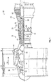
- FIG. 1 schematically illustrates a gas turbine engine 20.
- the gas turbine engine 20 is disclosed herein as a two-spool turbofan that generally incorporates a fan section 22, a compressor section 24, a combustor section 26 and a turbine section 28.
- Alternative engines might include other systems or features.
- the fan section 22 drives air along a bypass flow path B in a bypass duct, while the compressor section 24 drives air along a core flow path C for compression and communication into the combustor section 26 then expansion through the turbine section 28.
- FIG. 1 schematically illustrates a gas turbine engine 20.
- the gas turbine engine 20 is disclosed herein as a two-spool turbofan that generally incorporates a fan section 22, a compressor section 24, a combustor section 26 and a turbine section 28.
- Alternative engines might include other systems or features.
- the fan section 22 drives air along a bypass flow path B in a bypass duct
- the compressor section 24 drives air along a core flow path C for compression and communication into the combustor section 26
- the exemplary engine 20 generally includes a low speed spool 30 and a high speed spool 32 mounted for rotation about an engine central longitudinal axis A relative to an engine static structure 36 via several bearing systems 38. It should be understood that various bearing systems 38 at various locations may alternatively or additionally be provided, and the location of bearing systems 38 may be varied as appropriate to the application.
- the low speed spool 30 generally includes an inner shaft 40 that interconnects a fan 42, a low pressure compressor 44 and a low pressure turbine 46.
- the inner shaft 40 is connected to the fan 42 through a speed change mechanism, which in exemplary gas turbine engine 20 is illustrated as a geared architecture 48 to drive the fan 42 at a lower speed than the low speed spool 30.
- the high speed spool 32 includes an outer shaft 50 that interconnects a high pressure compressor 52 and high pressure turbine 54.
- a combustor 56 is arranged in exemplary gas turbine 20 between the high pressure compressor 52 and the high pressure turbine 54.
- An engine static structure 36 is arranged generally between the high pressure turbine 54 and the low pressure turbine 46.
- the engine static structure 36 further supports bearing systems 38 in the turbine section 28.
- the inner shaft 40 and the outer shaft 50 are concentric and rotate via bearing systems 38 about the engine central longitudinal axis which is collinear with their longitudinal axes.
- each of the positions of the fan section 22, compressor section 24, combustor section 26, turbine section 28, and fan drive gear system 48 may be varied.
- gear system 48 may be located aft of combustor section 26 or even aft of turbine section 28, and fan section 22 may be positioned forward or aft of the location of gear system 48.
- the gear system 48 may also not be provided should the gas turbine engine 20 not be a geared turbofan engine.
- the engine 20, in one example, is a high-bypass geared aircraft engine.
- the engine 20 bypass ratio is greater than about six (6), with an example embodiment being greater than about ten (10)
- the geared architecture 48 is an epicyclic gear train, such as a planetary gear system or other gear system, with a gear reduction ratio of greater than about 2.3 and the low pressure turbine 46 has a pressure ratio that is greater than about five.
- the engine 20 bypass ratio is greater than about ten (10:1)
- the fan diameter is significantly larger than that of the low pressure compressor 44
- the low pressure turbine 46 has a pressure ratio that is greater than about five (5:1).
- Low pressure turbine 46 pressure ratio is pressure measured prior to inlet of low pressure turbine 46 as related to the pressure at the outlet of the low pressure turbine 46 prior to an exhaust nozzle.
- the geared architecture 48 may be an epicycle gear train, such as a planetary gear system or other gear system, with a gear reduction ratio of greater than about 2.3:1. It should be understood, however, that the above parameters are only exemplary of one embodiment of a geared architecture engine and that the present disclosure is applicable to other gas turbine engines including direct drive turbofans.
- the fan section 22 of the engine 20 is designed for a particular flight condition--typically cruise at about 0.8 Mach and about 35,000 feet (10,668 meters).
- 'TSFC' Thrust Specific Fuel Consumption
- Low fan pressure ratio is the pressure ratio across the fan blade alone, without a Fan Exit Guide Vane (“FEGV”) system.
- the low fan pressure ratio as disclosed herein according to one non-limiting embodiment is less than about 1.45.
- Low corrected fan tip speed is the actual fan tip speed in ft/sec divided by an industry standard temperature correction of [(Tram °R)/(518.7 °R)] 0.5 .
- the "Low corrected fan tip speed” as disclosed herein according to one non-limiting embodiment is less than about 1150 ft/second (350.5 m/sec).
- the inner shaft 40, the outer shaft 50, or various rotors or discs of the gas turbine engine 20 may undergo individual balancing procedures prior to assembly into or with the gas turbine engine 20. After assembly of the inner shaft 40, outer shaft 50, or various rotors or discs with the gas turbine engine 20 an imbalance may be present or detected.
- a trim balance device 60 may be provided that attaches to a rotatable shaft or rotatable spool, e.g. the inner shaft 40 or the outer shaft 50, of the gas turbine engine 20 having provisions to allow for correction or balancing of the rotatable shaft while the gas turbine engine 20 is in a substantially assembled state.
- the trim balance device 60 enables a rotatable shaft or rotors of the gas turbine engine 20 to be balanced during the operational life of the engine without the removal of material from the rotatable shaft or rotors.
- a trim balance device 60 is at least partially disposed about and is attached to or connected to the inner shaft 40 and/or the outer shaft 50 of the gas turbine engine 20.
- the trim balance device 60 is arranged to correct unbalance or provide a magnitude of balance correction to at least a rotatable shaft (the inner shaft 40 and/or the outer shaft 50) or rotor/disc.
- the trim balance device 60 may be disposed about the inner shaft 40 and/or the outer shaft 50 and may be disposed aft/downstream of at least one of the high pressure turbine 54 and low pressure turbine 46 or disposed concentrically with the low pressure turbine 46 of the turbine section 28.
- the trim balance device 60 is shown attached to the inner shaft 40 that extends through the turbine section 28.
- a second rotatable shaft 70 is connected to the rotatable shaft (e.g. the inner shaft 40 and/or the outer shaft 50).
- the second rotatable shaft 70 may extend at least partially into the rotatable shaft and extends from the rotatable shaft along the central longitudinal axis A.
- the second rotatable shaft 70 may be a shaft adapted to connect to instrumentation or other devices.
- the trim balance device 60 may be connected to both the rotatable shaft and the second rotatable shaft 70 and may be arranged to correct for imbalance of at least one of the rotatable shaft and the second rotatable shaft 70.
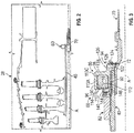
- the second rotatable shaft 70 defines a notch or a pocket 72 that extends from a surface of the second rotatable shaft 70 towards the central longitudinal axis A, as shown in FIG. 3 .
- the trim balance device 60 includes a trim balance nut 80 and a stack nut 82.
- the trim balance nut 80 is installed on and is at least partially disposed about the rotatable shaft.
- the trim balance nut 80 includes an outer surface 90, an inner surface 92, and a retention assembly 94.
- the outer surface 90 is disposed opposite the inner surface 92 that engages the rotatable shaft.
- the inner surface 92 may be provided with threads or other engagement features that engage engagement features that are defined by the rotatable shaft.
- the outer surface 90 and inner surface 92 each extend between a first trim balance nut end 96 and a second trim balance nut end 98 along the central longitudinal axis A.
- the trim balance nut 80 defines a plurality of apertures 106, as shown in FIGS. 4 and 5 .
- Each aperture 110 of the plurality of apertures 106 extends from the first trim balance nut end 96 towards the second trim balance nut end 98 such that the first trim balance nut end 96 is arranged as an open end and the second trim balance nut end 98 is arranged as a closed end.
- Each aperture 110 of the plurality of apertures 106 is arranged to receive and seat a balance weight 112.
- Each aperture 110 of the plurality of apertures 106 may include a chamfer 113C defined between a side surface 113A of a pair of side surfaces and an end surface 113B, as shown in FIGS. 3 and 4 .
- the chamfer 113C is arranged to facilitate the seating of the balance weight 112 in the aperture 110.
- a balance weight 112 may be disposed in an aperture 110 of the plurality of apertures 106 based on a determination of an unbalance of at least the rotatable shaft and an identification of a level of balance correction.
- the identification of the level of balance correction may also identify an aperture 110 of the plurality of apertures 106 that should receive the balance weight 112 to at least partially correct the imbalance or level of balance.
- the identification of the aperture 110 may correspond to an identification of a radial and/or circumferential location on a face 108 of the trim balance nut 80 that is disposed at the first trim balance nut end 96 that is located proximate an aperture 110.
- the trim balance nut 80 may be removed from the rotatable shaft and the balance weight 112 may be inserted into the identified aperture 110 of the trim balance nut 80.
- the trim balance nut 80 having at least one balance weight 112 installed/inserted into an identified aperture 110 is then reinstalled onto the rotatable shaft.
- the plurality of apertures 106 allows for various combinations of balance weights 112 to be disposed within various apertures or the same aperture about the trim balance nut 80 to fine tune the magnitude and/or angle of balance.
- a pair of balance weight may be disposed within an aperture at a first radial/circumferential location of the trim balance nut 80 without other balance weights being disposed in other apertures or a pair of balance weights may be disposed within an aperture at a first radial/circumferential location and another grouping of balance weights or a single balance weight may be disposed in another aperture at a second radial/circumferential location to obtain a different magnitude and/or angle of balance.
- the magnitude of balance correction may be refined using balance weights 112 having different material weights or various shapes (e.g. the center of the balance weight 112 may define an opening that extends completely through the balance weight by drilling or otherwise removing material or the outer diameter surface may define various cut outs or surface features providing a different magnitude of balance.
- the angle of balance correction may be refined by using balance weights 112 of different material weights or shapes as described above or the trim balance nut 80 itself may be positioned axially along the inner shaft 40 relative to the central longitudinal axis A to provide the desired balance correction. In such an arrangement, the trim balance nut 80 may be rotated circumferentially about the inner shaft 40 relative to the central longitudinal axis A to precisely position the trim balance nut 80 relative to the maximum unbalance at the axial location selected.
- the trim balance nut 80 may define a groove 114 that radially extends, relative to the central longitudinal axis A, from the aperture 110 towards at least one of the outer surface 90 and/or the inner surface 92.
- the groove 114 may axially extend, relative to the central longitudinal axis A, from the first trim balance nut end 96 towards the second trim balance nut end 98.
- the groove 114 may be a threaded groove or a non-threaded groove.
- the groove 114 is disposed proximate the first trim balance nut end 96.
- a retaining ring 116 may be received within the groove 114 and is arranged to axially retain the balance weight 112 within the aperture 110, as shown in FIG. 3 .
- the retention assembly 94 extends from the second trim balance nut end 98 and is arranged to retain the trim balance nut 80 to at least one of the rotatable shaft and the second rotatable shaft 70.
- the retention assembly 94 may include a first arm 120, a second arm 122, and a third arm 124.
- the first arm 120 extends from the second trim balance nut end 98 along the central longitudinal axis A.
- the second arm 122 extends from the first arm 120 and is disposed generally perpendicular to the first arm 120.
- the second arm 122 at least partially extends into the pocket 72 of the second rotatable shaft 70.
- the receiving of the second arm 122 in the pocket 72 assists in retaining the trim balance nut 80 to at least the second rotatable shaft 70.
- the third arm 124 extends from at least one of the first arm 120 and the second arm 122.
- the third arm 124 is spaced apart from the second rotatable shaft 70.
- the third arm 124 defines a
- a locking assembly 130 extends between the recess 126 of the third arm 124 and the pocket 72 of the second rotatable shaft 70.
- the locking assembly 130 is arranged to inhibit the trim balance nut 80 from loosening from at least one of the rotatable shaft and the second rotatable shaft 70.
- the locking assembly 130 may be a Vernier ring having tabs that lock into the recess 126 and a slot or the pocket 72 of the second rotatable shaft 70.
- the Vernier ring is arranged such that the ring may fit at any circumferential location of the trim balance nut 80 such that the trim balance nut 80 may be locked at the circumferential location.
- the stack nut 82 is disposed about the rotatable shaft and is spaced apart from the trim balance nut 80.
- the stack nut 82 includes a finger 140 or other feature that extends towards the first trim balance nut end 96.
- the finger 140 may be an engagement surface that does not extend towards the first trim balance nut end 96 but instead abuts or engages the first trim balance nut end 96.
- the finger 140 or engagement surface is arranged to axially retain the balance weight 112 within the aperture 110.
- the second arm 122 may not be provided with the retention assembly 94 such that only the first arm 120 and the third arm 124 are provided. In such an arrangement, the axially retaining of the trim balance nut 80 by the second arm 122 may not be necessary.
- the finger 140 may be provided with or instead of the retaining ring 116.
- the finger 140 may be provided as part of a plurality of fingers that are circumferentially spaced apart from each other by a gap 142, as shown in FIG. 5 .
- the plurality of fingers are arranged to axially retain a balance weight within respective apertures of the plurality of apertures 106.
- Each finger 140 defines a recess 144 that is arranged to receive a locking assembly 146 that extends between the recess 144 and a slot or a pocket defined by the rotatable shaft.
- the locking assembly 146 is arranged to inhibit the stack nut 82 from loosening from the rotatable shaft.
- the trim balance nut 80 of the trim balance device 60 provides a simple device that may be added to a rotatable shaft of the gas turbine engine 20 while the gas turbine engine 20 is in a substantially assembled state to enable the balance correction of a rotatable component of the gas turbine engine 20 without material removal.
- the trim balance nut 80 of the trim balance device 60 may provide an adjustable balance capability and may have a position that is variable or adjustable circumferentially or axially relative to the central longitudinal axis A to facilitate balance correction.
Landscapes
- Engineering & Computer Science (AREA)
- General Engineering & Computer Science (AREA)
- Mechanical Engineering (AREA)
- Physics & Mathematics (AREA)
- Acoustics & Sound (AREA)
- Aviation & Aerospace Engineering (AREA)
- Turbine Rotor Nozzle Sealing (AREA)
Applications Claiming Priority (1)
| Application Number | Priority Date | Filing Date | Title |
|---|---|---|---|
| US16/183,008 US11053798B2 (en) | 2018-11-07 | 2018-11-07 | Gas turbine engine having a trim balance |
Publications (2)
| Publication Number | Publication Date |
|---|---|
| EP3650636A1 true EP3650636A1 (fr) | 2020-05-13 |
| EP3650636B1 EP3650636B1 (fr) | 2022-01-26 |
Family
ID=67874314
Family Applications (1)
| Application Number | Title | Priority Date | Filing Date |
|---|---|---|---|
| EP19195570.7A Active EP3650636B1 (fr) | 2018-11-07 | 2019-09-05 | Moteur à turbine à gaz doté d'un équilibrage de garniture |
Country Status (2)
| Country | Link |
|---|---|
| US (1) | US11053798B2 (fr) |
| EP (1) | EP3650636B1 (fr) |
Families Citing this family (5)
| Publication number | Priority date | Publication date | Assignee | Title |
|---|---|---|---|---|
| CN112324860B (zh) * | 2020-11-03 | 2022-06-07 | 中国航发沈阳发动机研究所 | 一种发动机整机平衡结构 |
| US11976564B1 (en) * | 2023-03-30 | 2024-05-07 | Rolls-Royce North American Technologies Inc. | Splined balance weight for rotating components in gas turbine engines |
| US12018579B1 (en) | 2023-08-08 | 2024-06-25 | Rolls-Royce North American Technologies Inc. | Clocking balance weight rotor assembly for gas turbine engines |
| US12018580B1 (en) | 2023-08-08 | 2024-06-25 | Rolls-Royce North American Technologies Inc. | Rotor assembly for gas turbine engines with replaceable balance weight pins |
| US12305528B2 (en) | 2023-08-08 | 2025-05-20 | Rolls-Royce North American Technologies Inc. | Rotor assembly for gas turbine engines with replaceable balance weight bands |
Citations (3)
| Publication number | Priority date | Publication date | Assignee | Title |
|---|---|---|---|---|
| US4059972A (en) * | 1974-07-22 | 1977-11-29 | General Motors Corporation | Turbine shaft balancing |
| EP2447472A2 (fr) * | 2010-10-29 | 2012-05-02 | United Technologies Corporation | Équilibrage de garniture de moteur de turbine à gaz |
| FR3001515A1 (fr) * | 2013-01-25 | 2014-08-01 | Snecma | Assemblage de masselotte d'equilibrage a un element de rotor |
Family Cites Families (10)
| Publication number | Priority date | Publication date | Assignee | Title |
|---|---|---|---|---|
| DE4444992C2 (de) * | 1994-12-16 | 1997-04-17 | Hofmann Gmbh & Co Kg Maschinen | Vorrichtung zum Unwuchtausgleich von Rotationskörpern, insbesondere von Schleifscheiben |
| US7063507B2 (en) * | 2004-05-05 | 2006-06-20 | Hsieh Hsin-Mao | Balance adjusted fan |
| US20070253820A1 (en) * | 2006-04-30 | 2007-11-01 | Wen-Hao Liu | Adjustable device for balancing a fan |
| US8631578B2 (en) * | 2009-10-01 | 2014-01-21 | Pratt & Whitney Canada Corp. | Radial balancing clip weight for rotor assembly |
| JP4522493B1 (ja) * | 2010-02-19 | 2010-08-11 | 博明 山本 | バランサー |
| US20120121410A1 (en) * | 2010-11-11 | 2012-05-17 | Wen-Hao Liu | Round axial fan with balancing structure |
| US9932832B2 (en) * | 2014-05-29 | 2018-04-03 | Pratt & Whitney Canada Corp. | Method of balancing a spool of a gas turbine engine |
| US9739288B2 (en) * | 2014-10-09 | 2017-08-22 | Asia Vital Components Co., Ltd. | Fan hub balancing structure |
| US9556929B2 (en) | 2015-03-30 | 2017-01-31 | Hamilton Sundstrand Corporation | End fittings for drive shaft assemblies |
| CN106996392A (zh) * | 2016-01-26 | 2017-08-01 | 建准电机工业股份有限公司 | 风扇及其扇轮、平衡扇轮配重的方法及扇轮平衡系统 |
-
2018
- 2018-11-07 US US16/183,008 patent/US11053798B2/en active Active
-
2019
- 2019-09-05 EP EP19195570.7A patent/EP3650636B1/fr active Active
Patent Citations (3)
| Publication number | Priority date | Publication date | Assignee | Title |
|---|---|---|---|---|
| US4059972A (en) * | 1974-07-22 | 1977-11-29 | General Motors Corporation | Turbine shaft balancing |
| EP2447472A2 (fr) * | 2010-10-29 | 2012-05-02 | United Technologies Corporation | Équilibrage de garniture de moteur de turbine à gaz |
| FR3001515A1 (fr) * | 2013-01-25 | 2014-08-01 | Snecma | Assemblage de masselotte d'equilibrage a un element de rotor |
Also Published As
| Publication number | Publication date |
|---|---|
| EP3650636B1 (fr) | 2022-01-26 |
| US11053798B2 (en) | 2021-07-06 |
| US20200141240A1 (en) | 2020-05-07 |
Similar Documents
| Publication | Publication Date | Title |
|---|---|---|
| EP3650636B1 (fr) | Moteur à turbine à gaz doté d'un équilibrage de garniture | |
| EP3049624B1 (fr) | Bague d'équilibrage pour composant rotatif | |
| US10247003B2 (en) | Balanced rotating component for a gas powered engine | |
| US11168565B2 (en) | Heat shield insert | |
| US10544678B2 (en) | Gas turbine engine rotor disk balancing | |
| EP3760838B1 (fr) | Système d´aubes directrices d'une turbine á gaz et procédé | |
| EP3584406B1 (fr) | Équilibrage de pince et de broche pour rotor | |
| EP3418492B1 (fr) | Ensemble de rétention de boulon pour moteur de turbine à gaz | |
| EP3611338B1 (fr) | Système d'équilibrage pour une turbine à gaz avec contrepoids dans les queues d'aronde. | |
| EP3097289B1 (fr) | Structure et procédé d'équilibrage de moteur à turbine | |
| EP3933170B1 (fr) | Agencement de manchon à montage ventral | |
| US12416246B2 (en) | Bearing inner race with sleeve and integrated puller | |
| EP4524370A1 (fr) | Élément anti-rotation pour instrumentation de moteur à turbine à gaz | |
| EP3228856A1 (fr) | Élément de retrait de pale de soufflante pour moteur à turbine à gaz | |
| EP3575561A1 (fr) | Moteur à soufflante | |
| EP3045658B1 (fr) | Rotor de moteur de turbine à gaz |
Legal Events
| Date | Code | Title | Description |
|---|---|---|---|
| PUAI | Public reference made under article 153(3) epc to a published international application that has entered the european phase |
Free format text: ORIGINAL CODE: 0009012 |
|
| STAA | Information on the status of an ep patent application or granted ep patent |
Free format text: STATUS: THE APPLICATION HAS BEEN PUBLISHED |
|
| AK | Designated contracting states |
Kind code of ref document: A1 Designated state(s): AL AT BE BG CH CY CZ DE DK EE ES FI FR GB GR HR HU IE IS IT LI LT LU LV MC MK MT NL NO PL PT RO RS SE SI SK SM TR |
|
| AX | Request for extension of the european patent |
Extension state: BA ME |
|
| STAA | Information on the status of an ep patent application or granted ep patent |
Free format text: STATUS: REQUEST FOR EXAMINATION WAS MADE |
|
| 17P | Request for examination filed |
Effective date: 20201112 |
|
| RBV | Designated contracting states (corrected) |
Designated state(s): AL AT BE BG CH CY CZ DE DK EE ES FI FR GB GR HR HU IE IS IT LI LT LU LV MC MK MT NL NO PL PT RO RS SE SI SK SM TR |
|
| GRAP | Despatch of communication of intention to grant a patent |
Free format text: ORIGINAL CODE: EPIDOSNIGR1 |
|
| STAA | Information on the status of an ep patent application or granted ep patent |
Free format text: STATUS: GRANT OF PATENT IS INTENDED |
|
| INTG | Intention to grant announced |
Effective date: 20210115 |
|
| RAP1 | Party data changed (applicant data changed or rights of an application transferred) |
Owner name: RAYTHEON TECHNOLOGIES CORPORATION |
|
| GRAJ | Information related to disapproval of communication of intention to grant by the applicant or resumption of examination proceedings by the epo deleted |
Free format text: ORIGINAL CODE: EPIDOSDIGR1 |
|
| STAA | Information on the status of an ep patent application or granted ep patent |
Free format text: STATUS: REQUEST FOR EXAMINATION WAS MADE |
|
| INTC | Intention to grant announced (deleted) | ||
| GRAP | Despatch of communication of intention to grant a patent |
Free format text: ORIGINAL CODE: EPIDOSNIGR1 |
|
| STAA | Information on the status of an ep patent application or granted ep patent |
Free format text: STATUS: GRANT OF PATENT IS INTENDED |
|
| INTG | Intention to grant announced |
Effective date: 20210810 |
|
| GRAS | Grant fee paid |
Free format text: ORIGINAL CODE: EPIDOSNIGR3 |
|
| GRAA | (expected) grant |
Free format text: ORIGINAL CODE: 0009210 |
|
| STAA | Information on the status of an ep patent application or granted ep patent |
Free format text: STATUS: THE PATENT HAS BEEN GRANTED |
|
| AK | Designated contracting states |
Kind code of ref document: B1 Designated state(s): AL AT BE BG CH CY CZ DE DK EE ES FI FR GB GR HR HU IE IS IT LI LT LU LV MC MK MT NL NO PL PT RO RS SE SI SK SM TR |
|
| REG | Reference to a national code |
Ref country code: GB Ref legal event code: FG4D |
|
| REG | Reference to a national code |
Ref country code: CH Ref legal event code: EP |
|
| REG | Reference to a national code |
Ref country code: AT Ref legal event code: REF Ref document number: 1465438 Country of ref document: AT Kind code of ref document: T Effective date: 20220215 |
|
| REG | Reference to a national code |
Ref country code: IE Ref legal event code: FG4D |
|
| REG | Reference to a national code |
Ref country code: DE Ref legal event code: R096 Ref document number: 602019011179 Country of ref document: DE |
|
| REG | Reference to a national code |
Ref country code: LT Ref legal event code: MG9D |
|
| REG | Reference to a national code |
Ref country code: NL Ref legal event code: MP Effective date: 20220126 |
|
| REG | Reference to a national code |
Ref country code: AT Ref legal event code: MK05 Ref document number: 1465438 Country of ref document: AT Kind code of ref document: T Effective date: 20220126 |
|
| PG25 | Lapsed in a contracting state [announced via postgrant information from national office to epo] |
Ref country code: NL Free format text: LAPSE BECAUSE OF FAILURE TO SUBMIT A TRANSLATION OF THE DESCRIPTION OR TO PAY THE FEE WITHIN THE PRESCRIBED TIME-LIMIT Effective date: 20220126 |
|
| PG25 | Lapsed in a contracting state [announced via postgrant information from national office to epo] |
Ref country code: SE Free format text: LAPSE BECAUSE OF FAILURE TO SUBMIT A TRANSLATION OF THE DESCRIPTION OR TO PAY THE FEE WITHIN THE PRESCRIBED TIME-LIMIT Effective date: 20220126 Ref country code: RS Free format text: LAPSE BECAUSE OF FAILURE TO SUBMIT A TRANSLATION OF THE DESCRIPTION OR TO PAY THE FEE WITHIN THE PRESCRIBED TIME-LIMIT Effective date: 20220126 Ref country code: PT Free format text: LAPSE BECAUSE OF FAILURE TO SUBMIT A TRANSLATION OF THE DESCRIPTION OR TO PAY THE FEE WITHIN THE PRESCRIBED TIME-LIMIT Effective date: 20220526 Ref country code: NO Free format text: LAPSE BECAUSE OF FAILURE TO SUBMIT A TRANSLATION OF THE DESCRIPTION OR TO PAY THE FEE WITHIN THE PRESCRIBED TIME-LIMIT Effective date: 20220426 Ref country code: LT Free format text: LAPSE BECAUSE OF FAILURE TO SUBMIT A TRANSLATION OF THE DESCRIPTION OR TO PAY THE FEE WITHIN THE PRESCRIBED TIME-LIMIT Effective date: 20220126 Ref country code: HR Free format text: LAPSE BECAUSE OF FAILURE TO SUBMIT A TRANSLATION OF THE DESCRIPTION OR TO PAY THE FEE WITHIN THE PRESCRIBED TIME-LIMIT Effective date: 20220126 Ref country code: ES Free format text: LAPSE BECAUSE OF FAILURE TO SUBMIT A TRANSLATION OF THE DESCRIPTION OR TO PAY THE FEE WITHIN THE PRESCRIBED TIME-LIMIT Effective date: 20220126 Ref country code: BG Free format text: LAPSE BECAUSE OF FAILURE TO SUBMIT A TRANSLATION OF THE DESCRIPTION OR TO PAY THE FEE WITHIN THE PRESCRIBED TIME-LIMIT Effective date: 20220426 |
|
| PG25 | Lapsed in a contracting state [announced via postgrant information from national office to epo] |
Ref country code: PL Free format text: LAPSE BECAUSE OF FAILURE TO SUBMIT A TRANSLATION OF THE DESCRIPTION OR TO PAY THE FEE WITHIN THE PRESCRIBED TIME-LIMIT Effective date: 20220126 Ref country code: LV Free format text: LAPSE BECAUSE OF FAILURE TO SUBMIT A TRANSLATION OF THE DESCRIPTION OR TO PAY THE FEE WITHIN THE PRESCRIBED TIME-LIMIT Effective date: 20220126 Ref country code: GR Free format text: LAPSE BECAUSE OF FAILURE TO SUBMIT A TRANSLATION OF THE DESCRIPTION OR TO PAY THE FEE WITHIN THE PRESCRIBED TIME-LIMIT Effective date: 20220427 Ref country code: FI Free format text: LAPSE BECAUSE OF FAILURE TO SUBMIT A TRANSLATION OF THE DESCRIPTION OR TO PAY THE FEE WITHIN THE PRESCRIBED TIME-LIMIT Effective date: 20220126 Ref country code: AT Free format text: LAPSE BECAUSE OF FAILURE TO SUBMIT A TRANSLATION OF THE DESCRIPTION OR TO PAY THE FEE WITHIN THE PRESCRIBED TIME-LIMIT Effective date: 20220126 |
|
| PG25 | Lapsed in a contracting state [announced via postgrant information from national office to epo] |
Ref country code: IS Free format text: LAPSE BECAUSE OF FAILURE TO SUBMIT A TRANSLATION OF THE DESCRIPTION OR TO PAY THE FEE WITHIN THE PRESCRIBED TIME-LIMIT Effective date: 20220526 |
|
| REG | Reference to a national code |
Ref country code: DE Ref legal event code: R097 Ref document number: 602019011179 Country of ref document: DE |
|
| PG25 | Lapsed in a contracting state [announced via postgrant information from national office to epo] |
Ref country code: SM Free format text: LAPSE BECAUSE OF FAILURE TO SUBMIT A TRANSLATION OF THE DESCRIPTION OR TO PAY THE FEE WITHIN THE PRESCRIBED TIME-LIMIT Effective date: 20220126 Ref country code: SK Free format text: LAPSE BECAUSE OF FAILURE TO SUBMIT A TRANSLATION OF THE DESCRIPTION OR TO PAY THE FEE WITHIN THE PRESCRIBED TIME-LIMIT Effective date: 20220126 Ref country code: RO Free format text: LAPSE BECAUSE OF FAILURE TO SUBMIT A TRANSLATION OF THE DESCRIPTION OR TO PAY THE FEE WITHIN THE PRESCRIBED TIME-LIMIT Effective date: 20220126 Ref country code: EE Free format text: LAPSE BECAUSE OF FAILURE TO SUBMIT A TRANSLATION OF THE DESCRIPTION OR TO PAY THE FEE WITHIN THE PRESCRIBED TIME-LIMIT Effective date: 20220126 Ref country code: DK Free format text: LAPSE BECAUSE OF FAILURE TO SUBMIT A TRANSLATION OF THE DESCRIPTION OR TO PAY THE FEE WITHIN THE PRESCRIBED TIME-LIMIT Effective date: 20220126 Ref country code: CZ Free format text: LAPSE BECAUSE OF FAILURE TO SUBMIT A TRANSLATION OF THE DESCRIPTION OR TO PAY THE FEE WITHIN THE PRESCRIBED TIME-LIMIT Effective date: 20220126 |
|
| PG25 | Lapsed in a contracting state [announced via postgrant information from national office to epo] |
Ref country code: AL Free format text: LAPSE BECAUSE OF FAILURE TO SUBMIT A TRANSLATION OF THE DESCRIPTION OR TO PAY THE FEE WITHIN THE PRESCRIBED TIME-LIMIT Effective date: 20220126 |
|
| PLBE | No opposition filed within time limit |
Free format text: ORIGINAL CODE: 0009261 |
|
| STAA | Information on the status of an ep patent application or granted ep patent |
Free format text: STATUS: NO OPPOSITION FILED WITHIN TIME LIMIT |
|
| 26N | No opposition filed |
Effective date: 20221027 |
|
| PG25 | Lapsed in a contracting state [announced via postgrant information from national office to epo] |
Ref country code: SI Free format text: LAPSE BECAUSE OF FAILURE TO SUBMIT A TRANSLATION OF THE DESCRIPTION OR TO PAY THE FEE WITHIN THE PRESCRIBED TIME-LIMIT Effective date: 20220126 |
|
| PG25 | Lapsed in a contracting state [announced via postgrant information from national office to epo] |
Ref country code: MC Free format text: LAPSE BECAUSE OF FAILURE TO SUBMIT A TRANSLATION OF THE DESCRIPTION OR TO PAY THE FEE WITHIN THE PRESCRIBED TIME-LIMIT Effective date: 20220126 |
|
| REG | Reference to a national code |
Ref country code: CH Ref legal event code: PL |
|
| REG | Reference to a national code |
Ref country code: BE Ref legal event code: MM Effective date: 20220930 |
|
| P01 | Opt-out of the competence of the unified patent court (upc) registered |
Effective date: 20230521 |
|
| PG25 | Lapsed in a contracting state [announced via postgrant information from national office to epo] |
Ref country code: LU Free format text: LAPSE BECAUSE OF NON-PAYMENT OF DUE FEES Effective date: 20220905 |
|
| PG25 | Lapsed in a contracting state [announced via postgrant information from national office to epo] |
Ref country code: LI Free format text: LAPSE BECAUSE OF NON-PAYMENT OF DUE FEES Effective date: 20220930 Ref country code: IT Free format text: LAPSE BECAUSE OF FAILURE TO SUBMIT A TRANSLATION OF THE DESCRIPTION OR TO PAY THE FEE WITHIN THE PRESCRIBED TIME-LIMIT Effective date: 20220126 Ref country code: IE Free format text: LAPSE BECAUSE OF NON-PAYMENT OF DUE FEES Effective date: 20220905 Ref country code: CH Free format text: LAPSE BECAUSE OF NON-PAYMENT OF DUE FEES Effective date: 20220930 |
|
| PG25 | Lapsed in a contracting state [announced via postgrant information from national office to epo] |
Ref country code: BE Free format text: LAPSE BECAUSE OF NON-PAYMENT OF DUE FEES Effective date: 20220930 |
|
| PG25 | Lapsed in a contracting state [announced via postgrant information from national office to epo] |
Ref country code: CY Free format text: LAPSE BECAUSE OF FAILURE TO SUBMIT A TRANSLATION OF THE DESCRIPTION OR TO PAY THE FEE WITHIN THE PRESCRIBED TIME-LIMIT Effective date: 20220126 |
|
| PG25 | Lapsed in a contracting state [announced via postgrant information from national office to epo] |
Ref country code: MK Free format text: LAPSE BECAUSE OF FAILURE TO SUBMIT A TRANSLATION OF THE DESCRIPTION OR TO PAY THE FEE WITHIN THE PRESCRIBED TIME-LIMIT Effective date: 20220126 Ref country code: HU Free format text: LAPSE BECAUSE OF FAILURE TO SUBMIT A TRANSLATION OF THE DESCRIPTION OR TO PAY THE FEE WITHIN THE PRESCRIBED TIME-LIMIT; INVALID AB INITIO Effective date: 20190905 |
|
| PG25 | Lapsed in a contracting state [announced via postgrant information from national office to epo] |
Ref country code: TR Free format text: LAPSE BECAUSE OF FAILURE TO SUBMIT A TRANSLATION OF THE DESCRIPTION OR TO PAY THE FEE WITHIN THE PRESCRIBED TIME-LIMIT Effective date: 20220126 |
|
| PG25 | Lapsed in a contracting state [announced via postgrant information from national office to epo] |
Ref country code: MT Free format text: LAPSE BECAUSE OF FAILURE TO SUBMIT A TRANSLATION OF THE DESCRIPTION OR TO PAY THE FEE WITHIN THE PRESCRIBED TIME-LIMIT Effective date: 20220126 |
|
| REG | Reference to a national code |
Ref country code: DE Ref legal event code: R081 Ref document number: 602019011179 Country of ref document: DE Owner name: RTX CORPORATION (N.D.GES.D. STAATES DELAWARE),, US Free format text: FORMER OWNER: RAYTHEON TECHNOLOGIES CORPORATION, FARMINGTON, CT, US |
|
| PGFP | Annual fee paid to national office [announced via postgrant information from national office to epo] |
Ref country code: DE Payment date: 20250820 Year of fee payment: 7 |
|
| PGFP | Annual fee paid to national office [announced via postgrant information from national office to epo] |
Ref country code: GB Payment date: 20250822 Year of fee payment: 7 |
|
| PGFP | Annual fee paid to national office [announced via postgrant information from national office to epo] |
Ref country code: FR Payment date: 20250820 Year of fee payment: 7 |