EP3650653B1 - Continuation d'un tube de cisaillement à travers d'une plate-forme d'aube directrice en composite à matrice céramique pour le soutien structural dans un moteur à turbine à gaz - Google Patents
Continuation d'un tube de cisaillement à travers d'une plate-forme d'aube directrice en composite à matrice céramique pour le soutien structural dans un moteur à turbine à gaz Download PDFInfo
- Publication number
- EP3650653B1 EP3650653B1 EP19207261.9A EP19207261A EP3650653B1 EP 3650653 B1 EP3650653 B1 EP 3650653B1 EP 19207261 A EP19207261 A EP 19207261A EP 3650653 B1 EP3650653 B1 EP 3650653B1
- Authority
- EP
- European Patent Office
- Prior art keywords
- platform
- layer
- shear tube
- airfoil
- layers
- Prior art date
- Legal status (The legal status is an assumption and is not a legal conclusion. Google has not performed a legal analysis and makes no representation as to the accuracy of the status listed.)
- Active
Links
Images




Classifications
-
- F—MECHANICAL ENGINEERING; LIGHTING; HEATING; WEAPONS; BLASTING
- F01—MACHINES OR ENGINES IN GENERAL; ENGINE PLANTS IN GENERAL; STEAM ENGINES
- F01D—NON-POSITIVE DISPLACEMENT MACHINES OR ENGINES, e.g. STEAM TURBINES
- F01D9/00—Stators
- F01D9/02—Nozzles; Nozzle boxes; Stator blades; Guide conduits, e.g. individual nozzles
- F01D9/04—Nozzles; Nozzle boxes; Stator blades; Guide conduits, e.g. individual nozzles forming ring or sector
- F01D9/041—Nozzles; Nozzle boxes; Stator blades; Guide conduits, e.g. individual nozzles forming ring or sector using blades
-
- B—PERFORMING OPERATIONS; TRANSPORTING
- B29—WORKING OF PLASTICS; WORKING OF SUBSTANCES IN A PLASTIC STATE IN GENERAL
- B29C—SHAPING OR JOINING OF PLASTICS; SHAPING OF MATERIAL IN A PLASTIC STATE, NOT OTHERWISE PROVIDED FOR; AFTER-TREATMENT OF THE SHAPED PRODUCTS, e.g. REPAIRING
- B29C70/00—Shaping composites, i.e. plastics material comprising reinforcements, fillers or preformed parts, e.g. inserts
- B29C70/04—Shaping composites, i.e. plastics material comprising reinforcements, fillers or preformed parts, e.g. inserts comprising reinforcements only, e.g. self-reinforcing plastics
- B29C70/06—Fibrous reinforcements only
- B29C70/10—Fibrous reinforcements only characterised by the structure of fibrous reinforcements, e.g. hollow fibres
- B29C70/16—Fibrous reinforcements only characterised by the structure of fibrous reinforcements, e.g. hollow fibres using fibres of substantial or continuous length
- B29C70/24—Fibrous reinforcements only characterised by the structure of fibrous reinforcements, e.g. hollow fibres using fibres of substantial or continuous length oriented in at least three directions forming a three-dimensional [3D] structure
-
- F—MECHANICAL ENGINEERING; LIGHTING; HEATING; WEAPONS; BLASTING
- F01—MACHINES OR ENGINES IN GENERAL; ENGINE PLANTS IN GENERAL; STEAM ENGINES
- F01D—NON-POSITIVE DISPLACEMENT MACHINES OR ENGINES, e.g. STEAM TURBINES
- F01D5/00—Blades; Blade-carrying members; Heating, heat-insulating, cooling or antivibration means on the blades or the members
- F01D5/12—Blades
- F01D5/14—Form or construction
- F01D5/147—Construction, i.e. structural features, e.g. of weight-saving hollow blades
-
- F—MECHANICAL ENGINEERING; LIGHTING; HEATING; WEAPONS; BLASTING
- F01—MACHINES OR ENGINES IN GENERAL; ENGINE PLANTS IN GENERAL; STEAM ENGINES
- F01D—NON-POSITIVE DISPLACEMENT MACHINES OR ENGINES, e.g. STEAM TURBINES
- F01D5/00—Blades; Blade-carrying members; Heating, heat-insulating, cooling or antivibration means on the blades or the members
- F01D5/12—Blades
- F01D5/28—Selecting particular materials; Particular measures relating thereto; Measures against erosion or corrosion
- F01D5/282—Selecting composite materials, e.g. blades with reinforcing filaments
-
- B—PERFORMING OPERATIONS; TRANSPORTING
- B29—WORKING OF PLASTICS; WORKING OF SUBSTANCES IN A PLASTIC STATE IN GENERAL
- B29L—INDEXING SCHEME ASSOCIATED WITH SUBCLASS B29C, RELATING TO PARTICULAR ARTICLES
- B29L2031/00—Other particular articles
- B29L2031/08—Blades for rotors, stators, fans, turbines or the like, e.g. screw propellers
- B29L2031/082—Blades, e.g. for helicopters
-
- F—MECHANICAL ENGINEERING; LIGHTING; HEATING; WEAPONS; BLASTING
- F05—INDEXING SCHEMES RELATING TO ENGINES OR PUMPS IN VARIOUS SUBCLASSES OF CLASSES F01-F04
- F05D—INDEXING SCHEME FOR ASPECTS RELATING TO NON-POSITIVE-DISPLACEMENT MACHINES OR ENGINES, GAS-TURBINES OR JET-PROPULSION PLANTS
- F05D2230/00—Manufacture
- F05D2230/60—Assembly methods
-
- F—MECHANICAL ENGINEERING; LIGHTING; HEATING; WEAPONS; BLASTING
- F05—INDEXING SCHEMES RELATING TO ENGINES OR PUMPS IN VARIOUS SUBCLASSES OF CLASSES F01-F04
- F05D—INDEXING SCHEME FOR ASPECTS RELATING TO NON-POSITIVE-DISPLACEMENT MACHINES OR ENGINES, GAS-TURBINES OR JET-PROPULSION PLANTS
- F05D2240/00—Components
- F05D2240/10—Stators
- F05D2240/12—Fluid guiding means, e.g. vanes
-
- F—MECHANICAL ENGINEERING; LIGHTING; HEATING; WEAPONS; BLASTING
- F05—INDEXING SCHEMES RELATING TO ENGINES OR PUMPS IN VARIOUS SUBCLASSES OF CLASSES F01-F04
- F05D—INDEXING SCHEME FOR ASPECTS RELATING TO NON-POSITIVE-DISPLACEMENT MACHINES OR ENGINES, GAS-TURBINES OR JET-PROPULSION PLANTS
- F05D2240/00—Components
- F05D2240/80—Platforms for stationary or moving blades
-
- F—MECHANICAL ENGINEERING; LIGHTING; HEATING; WEAPONS; BLASTING
- F05—INDEXING SCHEMES RELATING TO ENGINES OR PUMPS IN VARIOUS SUBCLASSES OF CLASSES F01-F04
- F05D—INDEXING SCHEME FOR ASPECTS RELATING TO NON-POSITIVE-DISPLACEMENT MACHINES OR ENGINES, GAS-TURBINES OR JET-PROPULSION PLANTS
- F05D2300/00—Materials; Properties thereof
- F05D2300/60—Properties or characteristics given to material by treatment or manufacturing
- F05D2300/601—Fabrics
- F05D2300/6012—Woven fabrics
-
- F—MECHANICAL ENGINEERING; LIGHTING; HEATING; WEAPONS; BLASTING
- F05—INDEXING SCHEMES RELATING TO ENGINES OR PUMPS IN VARIOUS SUBCLASSES OF CLASSES F01-F04
- F05D—INDEXING SCHEME FOR ASPECTS RELATING TO NON-POSITIVE-DISPLACEMENT MACHINES OR ENGINES, GAS-TURBINES OR JET-PROPULSION PLANTS
- F05D2300/00—Materials; Properties thereof
- F05D2300/60—Properties or characteristics given to material by treatment or manufacturing
- F05D2300/603—Composites; e.g. fibre-reinforced
- F05D2300/6033—Ceramic matrix composites [CMC]
-
- F—MECHANICAL ENGINEERING; LIGHTING; HEATING; WEAPONS; BLASTING
- F05—INDEXING SCHEMES RELATING TO ENGINES OR PUMPS IN VARIOUS SUBCLASSES OF CLASSES F01-F04
- F05D—INDEXING SCHEME FOR ASPECTS RELATING TO NON-POSITIVE-DISPLACEMENT MACHINES OR ENGINES, GAS-TURBINES OR JET-PROPULSION PLANTS
- F05D2300/00—Materials; Properties thereof
- F05D2300/60—Properties or characteristics given to material by treatment or manufacturing
- F05D2300/603—Composites; e.g. fibre-reinforced
- F05D2300/6034—Orientation of fibres, weaving, ply angle
-
- Y—GENERAL TAGGING OF NEW TECHNOLOGICAL DEVELOPMENTS; GENERAL TAGGING OF CROSS-SECTIONAL TECHNOLOGIES SPANNING OVER SEVERAL SECTIONS OF THE IPC; TECHNICAL SUBJECTS COVERED BY FORMER USPC CROSS-REFERENCE ART COLLECTIONS [XRACs] AND DIGESTS
- Y02—TECHNOLOGIES OR APPLICATIONS FOR MITIGATION OR ADAPTATION AGAINST CLIMATE CHANGE
- Y02T—CLIMATE CHANGE MITIGATION TECHNOLOGIES RELATED TO TRANSPORTATION
- Y02T50/00—Aeronautics or air transport
- Y02T50/60—Efficient propulsion technologies, e.g. for aircraft
Definitions
- the disclosure relates generally to stator vanes in gas turbine engines and more particularly to ceramic matrix composite vanes.
- CMC stator vanes tend to have low relative strength compared to in plane load paths.
- US 2014/255178 A1 discloses a flow straightening vane made of composite materials which includes a core made up of three-dimensional woven textile rods which core is surrounded by a textile covering.
- the covering consists of two-dimensional, woven or stitched textiles, and three-dimensional textiles.
- the radial ends of the textile rods are folded in L-shape or T-shape to form outer and inner platforms.
- the core and the covering are connected together by a set of transverse fibers and are consolidated using a thermoset resin.
- US 2014/356151 A1 discloses a turbine engine vane made of composite material comprising a hollow airfoil with an internal passage extending along its entire length, an inner platform, and an outer platform.
- US 6 676 373 B2 discloses a part that constitutes a platform web and that has a shape close to the shape of the platform with an inside face and an outside face that are opposite each other.
- US 2012/055609 A1 discloses a method of fabricating a composite-material turbomachine blade.
- US 2018/119549 A1 discloses a ceramic matrix composite blade for use in a gas turbine engine.
- US 2014/010662 A1 discloses a method of forming an airfoil with an integrated platform.
- US 2013/039769 A1 discloses a process for producing components containing ceramic materials.
- the invention provides a ceramic matrix composite stator vane of a gas turbine engine as claimed in claim 1.
- a second shear tube extends through the airfoil into the first platform and the second platform parallel the first shear tube.
- the invention provides a gas turbine engine as claimed in claim 3.
- the invention provides a method of manufacturing a ceramic matrix composite stator vane as claimed in claim 4.
- Gas turbine engine 20 may be a two-spool turbofan that generally incorporates a fan section 22, a compressor section 24, a combustor section 26 and a turbine section 28.
- fan section 22 can drive air along a bypass flow-path B while compressor section 24 can drive air for compression and communication into combustor section 26 then expansion through turbine section 28.
- turbofan gas turbine engine 20 depicted as a turbofan gas turbine engine 20 herein, it should be understood that the concepts described herein are not limited to use with turbofans as the teachings may be applied to other types of turbine engines including turbojet engines, a low-bypass turbofans, a high bypass turbofans, or any other gas turbine known to those skilled in the art.
- Gas turbine engine 20 may generally comprise a low speed spool 30 and a high speed spool 32 mounted for rotation about an engine central longitudinal axis A-A' relative to an engine static structure 36 via one or more bearing systems 38 (shown as bearing system 38-1 and bearing system 38-2). It should be understood that various bearing systems 38 at various locations may alternatively or additionally be provided, including for example, bearing system 38, bearing system 38-1, and bearing system 38-2.
- Low speed spool 30 may generally comprise an inner shaft 40 that interconnects a fan 42, a low pressure (or first) compressor section 44 (also referred to a low pressure compressor) and a low pressure (or first) turbine section 46.
- Inner shaft 40 may be connected to fan 42 through a geared architecture 48 that can drive fan 42 at a lower speed than low speed spool 30.
- Geared architecture 48 may comprise a gear assembly 60 enclosed within a gear housing 62.
- Gear assembly 60 couples inner shaft 40 to a rotating fan structure.
- High speed spool 32 may comprise an outer shaft 50 that interconnects a high pressure compressor (“HPC") 52 (e.g., a second compressor section) and high pressure (or second) turbine section 54.
- HPC high pressure compressor
- a combustor 56 may be located between HPC 52 and high pressure turbine 54.
- a mid-turbine frame 57 of engine static structure 36 may be located generally between high pressure turbine 54 and low pressure turbine 46.
- Mid-turbine frame 57 may support one or more bearing systems 38 in turbine section 28.
- Inner shaft 40 and outer shaft 50 may be concentric and rotate via bearing systems 38 about the engine central longitudinal axis A-A', which is collinear with their longitudinal axes.
- a "high pressure" compressor or turbine experiences a higher pressure than a corresponding "low pressure” compressor or turbine.
- the core airflow C may be compressed by low pressure compressor 44 then HPC 52, mixed and burned with fuel in combustor 56, then expanded over high pressure turbine 54 and low pressure turbine 46.
- Mid-turbine frame 57 includes airfoils 59 which are in the core airflow path.
- Low pressure turbine 46, and high pressure turbine 54 rotationally drive the respective low speed spool 30 and high speed spool 32 in response to the expansion.
- Gas turbine engine 20 may be, for example, a high-bypass geared aircraft engine. In various configurations, the bypass ratio of gas turbine engine 20 may be greater than about six (6). In various configurations, the bypass ratio of gas turbine engine 20 may be greater than ten (10).
- geared architecture 48 may be an epicyclic gear train, such as a star gear system (sun gear in meshing engagement with a plurality of star gears supported by a carrier and in meshing engagement with a ring gear) or other gear system. Geared architecture 48 may have a gear reduction ratio of greater than about 2.3 and low pressure turbine 46 may have a pressure ratio that is greater than about 5. In various configurations, the bypass ratio of gas turbine engine 20 is greater than about ten (10:1).
- the diameter of fan 42 may be significantly larger than that of the low pressure compressor 44, and the low pressure turbine 46 may have a pressure ratio that is greater than about (5:1). Low pressure turbine 46 pressure ratio may be measured prior to inlet of low pressure turbine 46 as related to the pressure at the outlet of low pressure turbine 46 prior to an exhaust nozzle. It should be understood, however, that the above parameters are exemplary of various configurations of a suitable geared architecture engine and that the present disclosure contemplates other gas turbine engines including direct drive turbofans.
- next generation of turbofan engines may be designed for higher efficiency which is associated with higher pressure ratios and higher temperatures in the HPC 52.
- These higher operating temperatures and pressure ratios may create operating environments that may cause thermal loads that are higher than the thermal loads encountered in conventional turbofan engines, which may shorten the operational life of current components.
- HPC 52 may comprise alternating rows of rotating rotors and stationary stators.
- Stators may have a cantilevered configuration or a shrouded configuration.
- a stator may comprise a stator vane, a casing support and a hub support.
- a stator vane may be supported along an outer diameter by a casing support and along an inner diameter by a hub support.
- a cantilevered stator may comprise a stator vane that is only retained and/or supported at the casing (e.g., along an outer diameter).
- rotors may be configured to compress and spin a fluid flow.
- Stators may be configured to receive and straighten the fluid flow.
- the fluid flow discharged from the trailing edge of stators may be straightened (e.g., the flow may be directed in a substantially parallel path to the centerline of the engine and/or HPC) to increase and/or improve the efficiency of the engine and, more specifically, to achieve maximum and/or near maximum compression and efficiency when the straightened air is compressed and spun by rotor 64.
- a stator vane 200 having a shear tube is illustrated with XYZ-axes provided for reference.
- Stator vane 200 comprises an airfoil 206 extending between an inner gas path surface 208 of a first platform 204 (i.e. an inner platform) and an outer gas path surface 210 of a second platform 202 (i.e. an outer platform).
- the first platform 204 is defined between the inner gas path surface 208 and inner platform surface 214 and, in like regard, the second platform 202 is defined between the outer gas path surface 210 and the outer platform surface 212.
- one or more cores such as first core 216 and second core 218 may extend radially (along the Z-axis) through the airfoil 206.
- the cores 216 and 218 may open through outer platform surface 212 of second platform 202 and inner platform surface 214 of first platform 204.
- the inner platform surface 214 and the outer platform surface 212 may be in fluid communication through the first core 216 and second core 218.
- stator vane 200 may experience compressive loading force Fc in the radial direction (along the Z-axis) and may also experience aerodynamic shear loading Fs in the XY-plane.
- stator vane 200 comprises a plurality of stacked, layered, and/or wrapped matrix plies and/or weaves.
- stator vane 200 is a Ceramic Matrix Composite (CMC) material such as, for example, one of a silicon-carbide/silicon-carbide matrix, carbon/carbon matrix, carbon/silicon-carbide matrix, alumina matrix, mullite matrix, or a zirconium boride matrix.
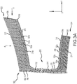
- FIG. 3A illustrates stator vane 200 in partial cross section through the ZY plane viewed along the X-axis.
- First platform 204 comprises a first plurality of platform plies 308 layered relatively coplanar with the XY plane and stacked (along the Z-axis).
- the second platform 202 comprises a second plurality of platform plies 306 layered relatively coplanar with the XY plane and stacked (along the Z-axis).
- the platform plies 306 and 308 may tend to be relatively resistant to compressive loading Fc but, in response to shear loading Fs applied relatively in plane to the platform plies 306 and 308, may tend to delaminate.
- Airfoil 206 is built up around one or more shear tubes 300 which may define the circumference of the first core 216 and the second core 218.
- Shear tubes 300 comprise one or more shear tube layers such as first shear tube layer 302 and second shear tube layer 304 which wrap around the Z-axis and extend along the Z-axis through the airfoil 206, the first platform 204 and the second platform 202.
- the shear tubes 300 are disposed relatively orthogonally (i.e. within 45°) to the first plurality of platform plies 308 and the second plurality of platform plies 306.
- the shear tubes 300 are relatively orthogonal to the first platform 204 and the second platform 202 and tend to resist aerodynamic shear force Fs tending thereby to inhibit delamination of the first plurality of platform plies 308 and the second plurality of platform plies 306.
- a shear tube 300 is wrapped, braided, and/or a triaxially braided shear tube.
- Airfoil 206 further includes one or more overbraid layers which wrap around the Z-axis about the shear tubes 300 such as first overbraid layer 316 and second overbraid layer 320.
- the overbraid layers are a continuous overbraid (e.g., a tube) with first platform ends (316a, 320a) and second platform ends (316b, 320b) feathered out and laid relatively in plane with the first plurality of platform plies 308 and the second plurality of platform plies 306 thereby forming a portion of the respective platform.
- a continuous overbraid e.g., a tube
- airfoil 206 includes a woven overlay 322 (e.g., a Y-weave overlay) about the overbraid layers with ends (322a, 322b) of the woven overlay 322 similarly feathered and laid relatively in plane with the first plurality of platform plies 308 and the second plurality of platform plies 306 and proximate first platform ends (316a, 320a) and second platform ends (316b, 320b).
- a woven overlay 322 e.g., a Y-weave overlay
- An aerodynamic layer 314 wraps over the woven overlay 322 forming the aerodynamic surface of airfoil 206 with ends (314a, 314b) similarly feathered and laid relatively in plane with the first plurality of platform plies 308 and the second plurality of platform plies 306 and respectively contacting the ends (322a, 322b) of the woven overlay 322.
- aerodynamic layer 314 may not fully overwrap the woven overlay 322 and may expose a portion 324 of the woven overlay 322 proximate the trailing edge 220 of airfoil 206.
- An inner gas path layer 312 is layered over first platform end 314a of aerodynamic layer 314 and defines the inner gas path surface 208.
- an outer gas path layer 310 is layered over the second platform end 314b of aerodynamic layer 314 and defines the outer gas path surface 210.
- airfoil 206 may be built up of multiple layers and a shear tube such as shear tube 300 may comprise any layer or any number of layers of an airfoil such as airfoil 206.
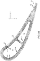
- Section 400 includes a plurality of axial fibers 402 which are wrapped relatively between first bias fibers 404 and second bias fibers 406.
- the intersection between the first bias fibers 404 and the axial fibers 402 define a first bias angle ⁇ and, in like regard, the intersection between the second bias fibers 406 and the axial fibers 402 define a second bias angle ⁇ .
- the first bias angle and the second bias angle may be configured to improve the material properties of a layer.
- bias angle ⁇ and bias angle ⁇ may be equal.
- bias angle ⁇ may be between 20° and 70° and bias angle ⁇ may be between 20° and 70°.
- the first shear tube layer 302 and the second shear tube layer 304 comprise triaxially braided layers having the axial fibers 402 oriented radially (parallel the Z-axis).
- shear tube 300 is a triaxially braided shear tube.
- the first overbraid layer 316 and second overbraid layer 320 comprise triaxially braided layers having the axial fibers 402 oriented axially (parallel the X-axis).
- aerodynamic shear force Fs may be transferred compressively through the layers of airfoil 206, first platform 204 and second platform 202 and, in response, tending to induce a bending and in plane shear force T in fibers (402, 404, 406) of the triaxially braided shear tubes 300 which tends to resist the transmitted aerodynamic shear force Fs.
- a closed section of shear tubes 300 tends to increase its shear loading capacity thereby tending to enhance the overall shear strength of vane 200.
- Method 500 includes selecting one or more core mandrels 526 to define a core such as first core 216 and second core 218 of vane 200 (step 502).
- a shear tube layer is applied to each of the selected mandrels 526 to form a shear tube (step 504).
- mandrels 526 are braided with first shear tube layer 302 and second shear tube layer 304 to form shear tubes 300.
- Method 500 includes joining the shear tubes 300 on the mandrels 526 to form a core configuration 528 (step 506).
- step 506 includes coupling the shear tubes 300 with a filler material such as, for example, individual fibers, bundles of fibers, chopped fiber, monolithic ceramic material, layered fabric material, pre-densified composites and/or the like.
- Method 500 includes applying an overbraid layer to the core configuration 528 to form an overbraided shear tube 530 (step 508).
- shear tubes 300 are wrapped with first overbraid layer 316 and second overbraid layer 320.
- Method 500 includes wrapping overbraided shear tube 530 with woven overlay 322 and may include adding the filler material to form an airfoil overlay 532 (step 510).
- Method 500 includes mounting mandrels 526 and airfoil overlay 532 in an a consolidation fixture (step 512) and applying a consolidation tool 534 to the airfoil overlay to form a consolidated airfoil overlay 536 (step 514).
- Method 500 includes removing consolidation tool 534 and wrapping consolidated airfoil overlay 536 with aerodynamic layer 314 to form layered airfoil 538 (step 516).
- Step 516 may include leaving an exposed portion 324 of woven overlay 322 proximate trailing edge 220.
- Method 500 includes applying consolidation tool 534 to layered airfoil 538 to consolidate the woven overlay 322 and the aerodynamic layer 314 to form airfoil 206 (step 518).
- Method 500 includes layering a gas path layer such as, inner gas path layer 312 and outer gas path layer 310, over the consolidation tool 534 relatively perpendicular (i.e. within 45°) the airfoil 206, feathering an airfoil layer over the gas path layer, and exposing a portion of the shear tubes 300 (step 520).
- Step 520 includes feathering ends of the aerodynamic layer, the overlay layer, and overwrap layers and folding (arrows 540) the feathered ends of respective aerodynamic, overlay, and overwrap layers over the respective gas path layer.
- step 520 includes folding second platform end 314b of aerodynamic layer 314 over outer gas path layer 310, and folding second platform end 322b of woven overlay 322 over second platform end 314b, and folding second platform ends 320b and 316b of second overbraid layer 320 and first overbraid layer 316 over second platform end 322b, thereby exposing second shear tube layer 304 of shear tube 300.
- Method 500 includes layering a plurality of platform layers over the airfoil layers and perpendicular to the exposed shear tube to form the first platform 204 and the second platform 202 (step 522).
- step 522 includes layering the second plurality of platform plies 306 over second platform end 316b of first overbraid layer 316 around the second shear tube layer 304 of shear tube 300.
- step 522 may include feathering and folding the ends of the shear tube layers over the plurality of platform plies.
- Method 500 includes consolidating the first platform 204, the second platform 202, and the airfoil 206 to form vane preform 542 (step 524).
- Step 524 includes curing the vane preform.
- Method 500 includes performing one of chemical vapor infiltration, melt infiltration, polymer infiltration, pyrolysis, or sintering on vane preform 542 to form stator vane 200.
- references to “one embodiment”, “an embodiment”, “an illustrated embodiment”, etc. indicate that the embodiment described includes a particular feature, structure, or characteristic, but every embodiment may not necessarily include the particular feature, structure, or characteristic. Moreover, such phrases are not necessarily referring to the same embodiment. Further, when a particular feature, structure, or characteristic is described in connection with an embodiment, it is submitted that it is within the knowledge of one skilled in the art to affect such feature, structure, or characteristic in connection with other embodiments not covered by the claimed invention, whether or not explicitly described. After reading the description, it will be apparent to one skilled in the relevant art(s) how to implement the disclosure in alternative examples.
- the terms “comprises”, “comprising”, or any other variation thereof, are intended to cover a non-exclusive inclusion, such that a process, method, article, or apparatus that comprises a list of elements does not include only those elements but may include other elements not expressly listed or inherent to such process, method, article, or apparatus.
Landscapes
- Engineering & Computer Science (AREA)
- Mechanical Engineering (AREA)
- General Engineering & Computer Science (AREA)
- Chemical & Material Sciences (AREA)
- Composite Materials (AREA)
- Materials Engineering (AREA)
- Textile Engineering (AREA)
- Architecture (AREA)
- Turbine Rotor Nozzle Sealing (AREA)
- Structures Of Non-Positive Displacement Pumps (AREA)
Claims (5)
- Aube de stator composite à matrice céramique (200) d'un moteur à turbine à gaz (20), comprenant :un profil aérodynamique (206) s'étendant entre une première plate-forme (204) et une seconde plate-forme (202) dans une direction radiale par rapport à un axe longitudinal central de moteur (A-A'),le profil aérodynamique (206) comportant un premier tube de cisaillement (300) définissant un noyau creux (216) du profil aérodynamique (206), une ou plusieurs couches surtressées (316, 320) enroulées autour du premier tube de cisaillement (300) et autour d'un axe radial (Z) par rapport à l'axe longitudinal central de moteur (A-A'), un revêtement tissé (322) autour des une ou plusieurs couches surtressées (316, 320), et une couche aérodynamique (314) enroulée sur le revêtement tissé (322) et formant une surface aérodynamique du profil aérodynamique (206),dans laquelle le premier tube de cisaillement s'étend de manière relativement orthogonale à la première plate-forme (204) et à la seconde plate-forme (202) et à travers celles-ci ; etdans laquelle le premier tube de cisaillement (300) est un tube de cisaillement tressé triaxialement et comprend une première couche de tube de cisaillement (302) et une seconde couche de tube de cisaillement (304), la première couche de tube de cisaillement (302) et la seconde couche de tube de cisaillement (304) comprenant chacune une couche tressée triaxialement ;dans laquelle les une ou plusieurs couches surtressées (316, 320) comprennent chacune une couche tressée triaxialement ;dans laquelle les couches tressées triaxialement comportent chacune une pluralité de fibres axiales (402) qui sont enroulées relativement entre des premières fibres en biais (404) et des secondes fibres en biais (406), l'intersection entre les premières fibres en biais (404) et les fibres axiales (402) définissant un premier angle en biais (a) et l'intersection entre les secondes fibres en biais (406) et les fibres axiales (402) définissant un second angle en biais (β) ;dans laquelle les fibres axiales (402) de la première couche de tube de cisaillement (302) et de la seconde couche de tube de cisaillement (304) sont orientées radialement par rapport à l'axe longitudinal central de moteur (A-A') ;dans laquelle les fibres axiales (402) des une ou plusieurs couches surtressées (316, 320) sont orientées axialement par rapport à l'axe longitudinal central de moteur (A-A') ;dans laquelle la première plate-forme (204) et la seconde plate-forme (202) comprennent une pluralité de couches de plate-forme ;dans laquelle la première plate-forme (204) comprend une première pluralité de plis de plate-forme (308) en couches autour de la seconde couche de tube de cisaillement (304) et une couche de trajet de gaz interne (312) définissant une surface de trajet de gaz interne (208) et dans laquelle la seconde plate-forme (202) comprend une seconde pluralité de plis de plate-forme (306) en couches autour de la seconde couche de tube de cisaillement (304) et une couche de trajet de gaz externe (310) définissant une surface de trajet de gaz externe (210) ;dans laquelle chacune des une ou plusieurs couches surtressées (316, 320) est une surtresse continue avec les premières extrémités de plate-forme (316a, 320a) et les secondes extrémités de plate-forme (316b, 320b) effilées et disposées relativement dans le plan avec la première pluralité de plis de plate-forme (308) et la seconde pluralité de plis de plate-forme (306) formant ainsi une partie de la plate-forme (204, 202) respective,dans laquelle le revêtement tissé (322) est un revêtement avec des extrémités (322a, 322b) effilées et disposées relativement dans le plan avec la première pluralité de plis de plate-forme (308) et la seconde pluralité de plis de plate-forme (306) et des premières extrémités de plate-forme proches (316a, 320a) et des secondes extrémités de plate-forme (316b, 320b) des une ou plusieurs couches surtressées (316, 320),dans laquelle la couche aérodynamique (314) est une couche avec des extrémités (314a, 314b) effilées et disposées relativement dans le plan avec la première pluralité de plis de plate-forme (308) et la seconde pluralité de plis de plate-forme (306) et des extrémités respectivement en contact (322a, 322b) du revêtement tissé (322),dans laquelle la couche de trajet de gaz interne (312) est superposée sur la première extrémité de plate-forme (314a) et la couche de trajet de gaz externe (310) est superposée sur la seconde extrémité de plate-forme (314b) de la couche aérodynamique (314),dans laquelle une force de cisaillement de flexion et dans le plan (T) est induite dans la pluralité de fibres du tube de cisaillement tressé triaxialement (300) en réponse à une force de cisaillement aérodynamique (Fs) transmise à travers la pluralité de couches de plate-forme.
- Aube de stator selon la revendication 1, comprenant en outre un second tube de cisaillement (300) s'étendant à travers le profil aérodynamique (206) dans la première plate-forme (204) et la seconde plate-forme (202) parallèlement au premier tube de cisaillement (300).
- Moteur à turbine à gaz (20) comprenant :une section de compresseur (24 ; 44) configurée pour comprimer un gaz ;une section de chambre de combustion (26) à l'arrière de la section de compresseur (24 ; 44) et configurée pour brûler le gaz ; etune aube de stator (200) selon une quelconque revendication précédente.
- Procédé de fabrication d'une aube de stator composite à matrice céramique (200) selon la revendication 1 ou 2, le procédé comprenant :la sélection d'un mandrin (526) pour définir le premier noyau de profil aérodynamique creux (216) de l'aube de stator (200) ;l'application de la première couche de tube de cisaillement (302) et de la seconde couche de tube de cisaillement (304) autour du mandrin (526) pour former le premier tube de cisaillement (300) ;l'application des une ou plusieurs couches surtressées (316, 320) sur le premier tube de cisaillement (300) pour former un tube de cisaillement surtressé (530) ;l'enroulement du tube de cisaillement surtressé (530) avec le revêtement tissé (322) pour former un revêtement de profil aérodynamique (532) ;l'application d'un outil de consolidation (534) sur le revêtement de profil aérodynamique (532) pour former un revêtement de profil aérodynamique consolidé (536) et l'enroulement du revêtement de profil aérodynamique consolidé (536) avec la couche aérodynamique (314) pour former un profil aérodynamique en couches (538) ;l'application de l'outil de consolidation (534) sur le profil aérodynamique en couches (538) pour consolider la couche aérodynamique (314) et le revêtement tissé (322) afin de former le profil aérodynamique (206) ;la disposition des couches de trajet de gaz interne et externe (312 ; 310) sur l'outil de consolidation (534) de manière relativement perpendiculaire au profil aérodynamique (206) ;l'effilage des extrémités (314a, 314b, 322a, 322b, 316a, 316b ; 320a, 320b) de la couche aérodynamique (314), du revêtement (322) et des une ou plusieurs couches surtressées (316, 320) et le pliage (flèches 540) des extrémités effilées (314a, 314b, 322a, 322b, 316a, 316b ; 320a, 320b) sur les couches de trajet de gaz (312 ; 310) respectives pour exposer une partie du premier tube de cisaillement (300), dans lequel l'étape de pliage comporte le pliage des première et seconde extrémités (314a, 314b) de la couche aérodynamique (314) sur les couches de trajet de gaz interne et externe (312, 310), le pliage des première et seconde extrémités (322a, 322b) du revêtement tissé (322) sur les première et seconde extrémités (314a, 314b) de la couche aérodynamique (314), et le pliage des première et seconde extrémités (316a ; 320a ; 316b ; 320b) des une ou plusieurs couches surtressées (316 ; 320) sur les première et seconde extrémités (322, 322b) du revêtement tissé (322), exposant ainsi la seconde couche de tube de cisaillement (304) du tube de cisaillement (300) ;la superposition des première et seconde pluralité de plis de plate-forme (308, 306) sur les première et seconde extrémités (316a, 320a, 316b ; 320b) des une ou plusieurs couches surtressées (316 ; 320) de manière relativement perpendiculaire à la partie exposée du premier tube de cisaillement (300) et autour de la seconde couche de tube de cisaillement (304) pour former la première plate-forme (204) et la seconde plate-forme (202) ;la consolidation et le durcissement de la première plate-forme, de la seconde plate-forme (202) et du profil aérodynamique (206) pour former une préforme d'aube (542) ; etla mise en œuvre de l'une parmi une infiltration chimique en phase vapeur, une infiltration par fusion, une infiltration de polymère, une pyrolyse ou un frittage sur la préforme d'aube (542) pour former l'aube de stator (200).
- Procédé selon la revendication 4, comprenant en outre l'assemblage d'un second tube de cisaillement (300) avec le premier tube de cisaillement (300) pour former une configuration de noyau (528) et l'enroulement de la configuration de noyau (528) avec les une ou plusieurs couches surtressées (316 ; 320) pour former le tube de cisaillement surtressé (530).
Applications Claiming Priority (1)
| Application Number | Priority Date | Filing Date | Title |
|---|---|---|---|
| US16/184,701 US10724387B2 (en) | 2018-11-08 | 2018-11-08 | Continuation of a shear tube through a vane platform for structural support |
Publications (2)
| Publication Number | Publication Date |
|---|---|
| EP3650653A1 EP3650653A1 (fr) | 2020-05-13 |
| EP3650653B1 true EP3650653B1 (fr) | 2021-12-29 |
Family
ID=68470268
Family Applications (1)
| Application Number | Title | Priority Date | Filing Date |
|---|---|---|---|
| EP19207261.9A Active EP3650653B1 (fr) | 2018-11-08 | 2019-11-05 | Continuation d'un tube de cisaillement à travers d'une plate-forme d'aube directrice en composite à matrice céramique pour le soutien structural dans un moteur à turbine à gaz |
Country Status (2)
| Country | Link |
|---|---|
| US (1) | US10724387B2 (fr) |
| EP (1) | EP3650653B1 (fr) |
Families Citing this family (18)
| Publication number | Priority date | Publication date | Assignee | Title |
|---|---|---|---|---|
| US11578609B2 (en) * | 2019-02-08 | 2023-02-14 | Raytheon Technologies Corporation | CMC component with integral cooling channels and method of manufacture |
| US11365635B2 (en) | 2019-05-17 | 2022-06-21 | Raytheon Technologies Corporation | CMC component with integral cooling channels and method of manufacture |
| US11162377B2 (en) | 2019-05-31 | 2021-11-02 | Rolls-Royce High Temperature Composites Inc. | Ceramic matrix composite turbine vane and method for making |
| US11242762B2 (en) | 2019-11-21 | 2022-02-08 | Raytheon Technologies Corporation | Vane with collar |
| US11492733B2 (en) * | 2020-02-21 | 2022-11-08 | Raytheon Technologies Corporation | Weave control grid |
| US11504930B2 (en) * | 2021-02-03 | 2022-11-22 | General Electric Company | Compaction system and methods for compacting composite components |
| US11530614B2 (en) | 2021-02-19 | 2022-12-20 | Raytheon Technologies Corporation | Vane arc segment formed of fiber-reinforced composite |
| US11346228B1 (en) * | 2021-02-23 | 2022-05-31 | Raytheon Technologies Corporation | Airfoil with flange formed of wishbone-shaped fiber layer structure |
| US11608748B2 (en) * | 2021-06-04 | 2023-03-21 | Raytheon Technologies Corporation | Preform crossovers for composite airfoils |
| US11560800B1 (en) * | 2021-11-12 | 2023-01-24 | Raytheon Technologies Corporation | Airfoil with fiber plies having interdigitated fingers in trailing end |
| US11506065B1 (en) * | 2021-11-12 | 2022-11-22 | Raytheon Technologies Corporation | Airfoil with serpentine fiber ply layup |
| US12071864B2 (en) | 2022-01-21 | 2024-08-27 | Rtx Corporation | Turbine section with ceramic support rings and ceramic vane arc segments |
| US11781435B2 (en) * | 2022-02-28 | 2023-10-10 | Rtx Corporation | Bifurcated fabric architecture for airfoils, methods of manufacture thereof and airfoils comprising the same |
| EP4283095B1 (fr) * | 2022-05-27 | 2025-09-10 | RTX Corporation | Aube stratifiée en cmc avec gouttes de pli |
| US11788419B1 (en) | 2022-08-15 | 2023-10-17 | Rtx Corporation | Airfoil leading edge venturi cooling passage |
| US12365633B2 (en) * | 2023-12-08 | 2025-07-22 | Rtx Corporation | Method to tie composite vane platform and airfoil design details |
| US12428965B2 (en) * | 2024-01-31 | 2025-09-30 | Rtx Corporation | Load bearing feature for ceramic matrix composite turbine components |
| US12529320B1 (en) | 2024-09-10 | 2026-01-20 | Rtx Corporation | Partial shear tube y-weave trailing edge for a CMC vane and method therefor |
Family Cites Families (43)
| Publication number | Priority date | Publication date | Assignee | Title |
|---|---|---|---|---|
| US4249291A (en) * | 1979-06-01 | 1981-02-10 | General Electric Company | Method for forming a liquid cooled airfoil for a gas turbine |
| US4314794A (en) * | 1979-10-25 | 1982-02-09 | Westinghouse Electric Corp. | Transpiration cooled blade for a gas turbine engine |
| FR2538029A1 (fr) * | 1982-12-15 | 1984-06-22 | Onera (Off Nat Aerospatiale) | Perfectionnements apportes aux aubes ceramiques, tournantes ou fixes de turbomachines |
| US6514046B1 (en) * | 2000-09-29 | 2003-02-04 | Siemens Westinghouse Power Corporation | Ceramic composite vane with metallic substructure |
| FR2817192B1 (fr) | 2000-11-28 | 2003-08-08 | Snecma Moteurs | Ensemble forme par au moins une pale et une plate-forme de fixation de la pale, pour une turbomachine, et procede pour sa fabrication |
| US6627019B2 (en) * | 2000-12-18 | 2003-09-30 | David C. Jarmon | Process for making ceramic matrix composite parts with cooling channels |
| US7410342B2 (en) * | 2005-05-05 | 2008-08-12 | Florida Turbine Technologies, Inc. | Airfoil support |
| DE102007027465A1 (de) * | 2007-06-14 | 2008-12-18 | Rolls-Royce Deutschland Ltd & Co Kg | Gasturbinenschaufel mit modularem Aufbau |
| US8142137B2 (en) * | 2008-11-26 | 2012-03-27 | Alstom Technology Ltd | Cooled gas turbine vane assembly |
| US8714932B2 (en) | 2008-12-31 | 2014-05-06 | General Electric Company | Ceramic matrix composite blade having integral platform structures and methods of fabrication |
| GB0901189D0 (en) | 2009-01-26 | 2009-03-11 | Rolls Royce Plc | Manufacturing a composite component |
| FR2943942B1 (fr) | 2009-04-06 | 2016-01-29 | Snecma | Procede de fabrication d'une aube de turbomachine en materiau composite |
| IT1397057B1 (it) | 2009-11-23 | 2012-12-28 | Nuovo Pignone Spa | Girante centrifuga e turbomacchina |
| EP2436884A1 (fr) * | 2010-09-29 | 2012-04-04 | Siemens Aktiengesellschaft | Agencement de turbine et moteur à turbine à gaz |
| US9334743B2 (en) * | 2011-05-26 | 2016-05-10 | United Technologies Corporation | Ceramic matrix composite airfoil for a gas turbine engine |
| US9011085B2 (en) * | 2011-05-26 | 2015-04-21 | United Technologies Corporation | Ceramic matrix composite continuous “I”-shaped fiber geometry airfoil for a gas turbine engine |
| US9103214B2 (en) | 2011-08-23 | 2015-08-11 | United Technologies Corporation | Ceramic matrix composite vane structure with overwrap for a gas turbine engine |
| FR2983261B1 (fr) | 2011-11-24 | 2014-11-28 | Aircelle Sa | Aube de redressement de flux d'air pour moteur d'aeronef et structure de redressement de flux associee |
| FR2983428B1 (fr) * | 2011-12-01 | 2014-01-17 | Snecma Propulsion Solide | Procede de fabrication d'une aube de turbomachine en materiau composite a plates-formes integrees |
| US8967961B2 (en) * | 2011-12-01 | 2015-03-03 | United Technologies Corporation | Ceramic matrix composite airfoil structure with trailing edge support for a gas turbine engine |
| FR2983519B1 (fr) | 2011-12-01 | 2015-07-24 | Snecma Propulsion Solide | Aube de turbine a pale creuse en materiau composite, turbine ou compresseur ayant un distributeur ou redresseur forme de telles aubes et turbomachine les comprenant |
| US9308708B2 (en) | 2012-03-23 | 2016-04-12 | General Electric Company | Process for producing ceramic composite components |
| BR112015000081A2 (pt) | 2012-06-30 | 2017-06-27 | Gen Electric | estrutura de vedação de pá de turbina. |
| US20140010662A1 (en) | 2012-07-03 | 2014-01-09 | United Technologies Corporation | Composite airfoil with integral platform |
| US9149997B2 (en) | 2012-09-14 | 2015-10-06 | United Technologies | Composite flange from braided preform |
| EP3027853B1 (fr) * | 2013-07-29 | 2021-05-19 | Raytheon Technologies Corporation | Ensemble à surface aérodynamique en cmc pour moteur à turbine à gaz |
| FR3008920B1 (fr) * | 2013-07-29 | 2015-12-25 | Safran | Procede de fabrication d'une aube en materiau composite a bord d'attaque metallique integre pour moteur aeronautique a turbine a gaz |
| EP2907974B1 (fr) * | 2014-02-12 | 2020-10-07 | United Technologies Corporation | Composant et moteur à turbine à gaz associé |
| FR3018308B1 (fr) * | 2014-03-06 | 2016-04-08 | Herakles | Secteur de stator pour turbomachine et son procede de fabrication |
| JP6372210B2 (ja) * | 2014-07-14 | 2018-08-15 | 株式会社Ihi | セラミックス基複合材料よりなるタービン静翼 |
| US10563522B2 (en) | 2014-09-22 | 2020-02-18 | Rolls-Royce North American Technologies Inc. | Composite airfoil for a gas turbine engine |
| US10094239B2 (en) * | 2014-10-31 | 2018-10-09 | Rolls-Royce North American Technologies Inc. | Vane assembly for a gas turbine engine |
| US10507515B2 (en) * | 2014-12-15 | 2019-12-17 | United Technologies Corporation | Ceramic core for component casting |
| EP3048254B1 (fr) * | 2015-01-22 | 2017-12-27 | Rolls-Royce Corporation | Ensemble de stator pour moteur de turbine à gaz |
| US10024172B2 (en) * | 2015-02-27 | 2018-07-17 | United Technologies Corporation | Gas turbine engine airfoil |
| US10408084B2 (en) | 2015-03-02 | 2019-09-10 | Rolls-Royce North American Technologies Inc. | Vane assembly for a gas turbine engine |
| EP3075531B1 (fr) * | 2015-03-31 | 2024-03-20 | Ansaldo Energia IP UK Limited | Dispositif sandwich avec panneaux céramiques et feutres en céramique |
| US10443409B2 (en) | 2016-10-28 | 2019-10-15 | Rolls-Royce North American Technologies Inc. | Turbine blade with ceramic matrix composite material construction |
| US10577939B2 (en) | 2016-11-01 | 2020-03-03 | Rolls-Royce Corporation | Turbine blade with three-dimensional CMC construction elements |
| US10436049B2 (en) * | 2016-11-17 | 2019-10-08 | United Technologies Corporation | Airfoil with dual profile leading end |
| US11014857B2 (en) * | 2017-09-20 | 2021-05-25 | General Electric Company | Contact interface for a composite component and methods of fabrication |
| US10415428B2 (en) * | 2018-01-31 | 2019-09-17 | United Technologies Corporation | Dual cavity baffle |
| US11041394B2 (en) * | 2018-06-01 | 2021-06-22 | Rolls-Royce Corporation | CMC airfoil joint |
-
2018
- 2018-11-08 US US16/184,701 patent/US10724387B2/en active Active
-
2019
- 2019-11-05 EP EP19207261.9A patent/EP3650653B1/fr active Active
Also Published As
| Publication number | Publication date |
|---|---|
| EP3650653A1 (fr) | 2020-05-13 |
| US10724387B2 (en) | 2020-07-28 |
| US20200149423A1 (en) | 2020-05-14 |
Similar Documents
| Publication | Publication Date | Title |
|---|---|---|
| EP3650653B1 (fr) | Continuation d'un tube de cisaillement à travers d'une plate-forme d'aube directrice en composite à matrice céramique pour le soutien structural dans un moteur à turbine à gaz | |
| US10975706B2 (en) | Frustic load transmission feature for composite structures | |
| CN114704335B (zh) | 具有单独的翼型件、内带和外带的复合翼型组件 | |
| EP2935799B1 (fr) | Fabrication d'ensemble aube à entretoise de couronne complète | |
| EP3156606A2 (fr) | Anneau de cerclage et procédés de formation de composants de turbine | |
| US20160215645A1 (en) | Blade outer air seal made of ceramic matrix composite | |
| EP2961938B1 (fr) | Aube composite d'une moteur de turbine à gaz et procédé | |
| US11377969B2 (en) | Extended root region and platform over-wrap for a blade of a gas turbine engine | |
| EP3553280B1 (fr) | Boîtier de soufflante avec couches entrelacées | |
| EP2959131B1 (fr) | Structure d'attachement composite à armure 3d | |
| EP3456931B1 (fr) | Système de confinement composite-métallique hybride stratifié pour moteurs à turbine à gaz | |
| US20210262416A1 (en) | Turbofan engine with core exhaust and bypass flow mixing | |
| US11105209B2 (en) | Turbine blade tip shroud | |
| EP3159324B1 (fr) | Fabrication de composants de moteur à turbine à gaz à l'aide de multiples étapes de traitement | |
| EP4461925A1 (fr) | Procédé pour surface portante en cmc utilisant un tube central en tissu céramique rigidifié | |
| CN120921742A (zh) | 制造燃气涡轮发动机的复合部件的方法 |
Legal Events
| Date | Code | Title | Description |
|---|---|---|---|
| PUAI | Public reference made under article 153(3) epc to a published international application that has entered the european phase |
Free format text: ORIGINAL CODE: 0009012 |
|
| STAA | Information on the status of an ep patent application or granted ep patent |
Free format text: STATUS: THE APPLICATION HAS BEEN PUBLISHED |
|
| AK | Designated contracting states |
Kind code of ref document: A1 Designated state(s): AL AT BE BG CH CY CZ DE DK EE ES FI FR GB GR HR HU IE IS IT LI LT LU LV MC MK MT NL NO PL PT RO RS SE SI SK SM TR |
|
| AX | Request for extension of the european patent |
Extension state: BA ME |
|
| STAA | Information on the status of an ep patent application or granted ep patent |
Free format text: STATUS: REQUEST FOR EXAMINATION WAS MADE |
|
| STAA | Information on the status of an ep patent application or granted ep patent |
Free format text: STATUS: EXAMINATION IS IN PROGRESS |
|
| 17P | Request for examination filed |
Effective date: 20201113 |
|
| RBV | Designated contracting states (corrected) |
Designated state(s): AL AT BE BG CH CY CZ DE DK EE ES FI FR GB GR HR HU IE IS IT LI LT LU LV MC MK MT NL NO PL PT RO RS SE SI SK SM TR |
|
| 17Q | First examination report despatched |
Effective date: 20201211 |
|
| RAP1 | Party data changed (applicant data changed or rights of an application transferred) |
Owner name: RAYTHEON TECHNOLOGIES CORPORATION |
|
| GRAP | Despatch of communication of intention to grant a patent |
Free format text: ORIGINAL CODE: EPIDOSNIGR1 |
|
| STAA | Information on the status of an ep patent application or granted ep patent |
Free format text: STATUS: GRANT OF PATENT IS INTENDED |
|
| INTG | Intention to grant announced |
Effective date: 20210625 |
|
| GRAS | Grant fee paid |
Free format text: ORIGINAL CODE: EPIDOSNIGR3 |
|
| GRAA | (expected) grant |
Free format text: ORIGINAL CODE: 0009210 |
|
| STAA | Information on the status of an ep patent application or granted ep patent |
Free format text: STATUS: THE PATENT HAS BEEN GRANTED |
|
| AK | Designated contracting states |
Kind code of ref document: B1 Designated state(s): AL AT BE BG CH CY CZ DE DK EE ES FI FR GB GR HR HU IE IS IT LI LT LU LV MC MK MT NL NO PL PT RO RS SE SI SK SM TR |
|
| REG | Reference to a national code |
Ref country code: GB Ref legal event code: FG4D |
|
| REG | Reference to a national code |
Ref country code: CH Ref legal event code: EP |
|
| REG | Reference to a national code |
Ref country code: AT Ref legal event code: REF Ref document number: 1458816 Country of ref document: AT Kind code of ref document: T Effective date: 20220115 |
|
| REG | Reference to a national code |
Ref country code: IE Ref legal event code: FG4D |
|
| REG | Reference to a national code |
Ref country code: DE Ref legal event code: R096 Ref document number: 602019010433 Country of ref document: DE |
|
| REG | Reference to a national code |
Ref country code: LT Ref legal event code: MG9D |
|
| PG25 | Lapsed in a contracting state [announced via postgrant information from national office to epo] |
Ref country code: RS Free format text: LAPSE BECAUSE OF FAILURE TO SUBMIT A TRANSLATION OF THE DESCRIPTION OR TO PAY THE FEE WITHIN THE PRESCRIBED TIME-LIMIT Effective date: 20211229 Ref country code: LT Free format text: LAPSE BECAUSE OF FAILURE TO SUBMIT A TRANSLATION OF THE DESCRIPTION OR TO PAY THE FEE WITHIN THE PRESCRIBED TIME-LIMIT Effective date: 20211229 Ref country code: FI Free format text: LAPSE BECAUSE OF FAILURE TO SUBMIT A TRANSLATION OF THE DESCRIPTION OR TO PAY THE FEE WITHIN THE PRESCRIBED TIME-LIMIT Effective date: 20211229 Ref country code: BG Free format text: LAPSE BECAUSE OF FAILURE TO SUBMIT A TRANSLATION OF THE DESCRIPTION OR TO PAY THE FEE WITHIN THE PRESCRIBED TIME-LIMIT Effective date: 20220329 |
|
| REG | Reference to a national code |
Ref country code: NL Ref legal event code: MP Effective date: 20211229 |
|
| REG | Reference to a national code |
Ref country code: AT Ref legal event code: MK05 Ref document number: 1458816 Country of ref document: AT Kind code of ref document: T Effective date: 20211229 |
|
| PG25 | Lapsed in a contracting state [announced via postgrant information from national office to epo] |
Ref country code: SE Free format text: LAPSE BECAUSE OF FAILURE TO SUBMIT A TRANSLATION OF THE DESCRIPTION OR TO PAY THE FEE WITHIN THE PRESCRIBED TIME-LIMIT Effective date: 20211229 Ref country code: NO Free format text: LAPSE BECAUSE OF FAILURE TO SUBMIT A TRANSLATION OF THE DESCRIPTION OR TO PAY THE FEE WITHIN THE PRESCRIBED TIME-LIMIT Effective date: 20220329 Ref country code: LV Free format text: LAPSE BECAUSE OF FAILURE TO SUBMIT A TRANSLATION OF THE DESCRIPTION OR TO PAY THE FEE WITHIN THE PRESCRIBED TIME-LIMIT Effective date: 20211229 Ref country code: HR Free format text: LAPSE BECAUSE OF FAILURE TO SUBMIT A TRANSLATION OF THE DESCRIPTION OR TO PAY THE FEE WITHIN THE PRESCRIBED TIME-LIMIT Effective date: 20211229 Ref country code: GR Free format text: LAPSE BECAUSE OF FAILURE TO SUBMIT A TRANSLATION OF THE DESCRIPTION OR TO PAY THE FEE WITHIN THE PRESCRIBED TIME-LIMIT Effective date: 20220330 |
|
| PG25 | Lapsed in a contracting state [announced via postgrant information from national office to epo] |
Ref country code: NL Free format text: LAPSE BECAUSE OF FAILURE TO SUBMIT A TRANSLATION OF THE DESCRIPTION OR TO PAY THE FEE WITHIN THE PRESCRIBED TIME-LIMIT Effective date: 20211229 |
|
| PG25 | Lapsed in a contracting state [announced via postgrant information from national office to epo] |
Ref country code: SM Free format text: LAPSE BECAUSE OF FAILURE TO SUBMIT A TRANSLATION OF THE DESCRIPTION OR TO PAY THE FEE WITHIN THE PRESCRIBED TIME-LIMIT Effective date: 20211229 Ref country code: SK Free format text: LAPSE BECAUSE OF FAILURE TO SUBMIT A TRANSLATION OF THE DESCRIPTION OR TO PAY THE FEE WITHIN THE PRESCRIBED TIME-LIMIT Effective date: 20211229 Ref country code: RO Free format text: LAPSE BECAUSE OF FAILURE TO SUBMIT A TRANSLATION OF THE DESCRIPTION OR TO PAY THE FEE WITHIN THE PRESCRIBED TIME-LIMIT Effective date: 20211229 Ref country code: PT Free format text: LAPSE BECAUSE OF FAILURE TO SUBMIT A TRANSLATION OF THE DESCRIPTION OR TO PAY THE FEE WITHIN THE PRESCRIBED TIME-LIMIT Effective date: 20220429 Ref country code: ES Free format text: LAPSE BECAUSE OF FAILURE TO SUBMIT A TRANSLATION OF THE DESCRIPTION OR TO PAY THE FEE WITHIN THE PRESCRIBED TIME-LIMIT Effective date: 20211229 Ref country code: EE Free format text: LAPSE BECAUSE OF FAILURE TO SUBMIT A TRANSLATION OF THE DESCRIPTION OR TO PAY THE FEE WITHIN THE PRESCRIBED TIME-LIMIT Effective date: 20211229 Ref country code: CZ Free format text: LAPSE BECAUSE OF FAILURE TO SUBMIT A TRANSLATION OF THE DESCRIPTION OR TO PAY THE FEE WITHIN THE PRESCRIBED TIME-LIMIT Effective date: 20211229 |
|
| PG25 | Lapsed in a contracting state [announced via postgrant information from national office to epo] |
Ref country code: PL Free format text: LAPSE BECAUSE OF FAILURE TO SUBMIT A TRANSLATION OF THE DESCRIPTION OR TO PAY THE FEE WITHIN THE PRESCRIBED TIME-LIMIT Effective date: 20211229 Ref country code: AT Free format text: LAPSE BECAUSE OF FAILURE TO SUBMIT A TRANSLATION OF THE DESCRIPTION OR TO PAY THE FEE WITHIN THE PRESCRIBED TIME-LIMIT Effective date: 20211229 |
|
| PG25 | Lapsed in a contracting state [announced via postgrant information from national office to epo] |
Ref country code: IS Free format text: LAPSE BECAUSE OF FAILURE TO SUBMIT A TRANSLATION OF THE DESCRIPTION OR TO PAY THE FEE WITHIN THE PRESCRIBED TIME-LIMIT Effective date: 20220429 |
|
| REG | Reference to a national code |
Ref country code: DE Ref legal event code: R097 Ref document number: 602019010433 Country of ref document: DE |
|
| PG25 | Lapsed in a contracting state [announced via postgrant information from national office to epo] |
Ref country code: DK Free format text: LAPSE BECAUSE OF FAILURE TO SUBMIT A TRANSLATION OF THE DESCRIPTION OR TO PAY THE FEE WITHIN THE PRESCRIBED TIME-LIMIT Effective date: 20211229 Ref country code: AL Free format text: LAPSE BECAUSE OF FAILURE TO SUBMIT A TRANSLATION OF THE DESCRIPTION OR TO PAY THE FEE WITHIN THE PRESCRIBED TIME-LIMIT Effective date: 20211229 |
|
| PLBE | No opposition filed within time limit |
Free format text: ORIGINAL CODE: 0009261 |
|
| STAA | Information on the status of an ep patent application or granted ep patent |
Free format text: STATUS: NO OPPOSITION FILED WITHIN TIME LIMIT |
|
| 26N | No opposition filed |
Effective date: 20220930 |
|
| PG25 | Lapsed in a contracting state [announced via postgrant information from national office to epo] |
Ref country code: SI Free format text: LAPSE BECAUSE OF FAILURE TO SUBMIT A TRANSLATION OF THE DESCRIPTION OR TO PAY THE FEE WITHIN THE PRESCRIBED TIME-LIMIT Effective date: 20211229 |
|
| PG25 | Lapsed in a contracting state [announced via postgrant information from national office to epo] |
Ref country code: IT Free format text: LAPSE BECAUSE OF FAILURE TO SUBMIT A TRANSLATION OF THE DESCRIPTION OR TO PAY THE FEE WITHIN THE PRESCRIBED TIME-LIMIT Effective date: 20211229 |
|
| P01 | Opt-out of the competence of the unified patent court (upc) registered |
Effective date: 20230521 |
|
| PG25 | Lapsed in a contracting state [announced via postgrant information from national office to epo] |
Ref country code: MC Free format text: LAPSE BECAUSE OF FAILURE TO SUBMIT A TRANSLATION OF THE DESCRIPTION OR TO PAY THE FEE WITHIN THE PRESCRIBED TIME-LIMIT Effective date: 20211229 |
|
| REG | Reference to a national code |
Ref country code: CH Ref legal event code: PL |
|
| REG | Reference to a national code |
Ref country code: BE Ref legal event code: MM Effective date: 20221130 |
|
| PG25 | Lapsed in a contracting state [announced via postgrant information from national office to epo] |
Ref country code: LI Free format text: LAPSE BECAUSE OF NON-PAYMENT OF DUE FEES Effective date: 20221130 Ref country code: CH Free format text: LAPSE BECAUSE OF NON-PAYMENT OF DUE FEES Effective date: 20221130 |
|
| PG25 | Lapsed in a contracting state [announced via postgrant information from national office to epo] |
Ref country code: LU Free format text: LAPSE BECAUSE OF NON-PAYMENT OF DUE FEES Effective date: 20221105 |
|
| PG25 | Lapsed in a contracting state [announced via postgrant information from national office to epo] |
Ref country code: IE Free format text: LAPSE BECAUSE OF NON-PAYMENT OF DUE FEES Effective date: 20221105 |
|
| PG25 | Lapsed in a contracting state [announced via postgrant information from national office to epo] |
Ref country code: BE Free format text: LAPSE BECAUSE OF NON-PAYMENT OF DUE FEES Effective date: 20221130 |
|
| PG25 | Lapsed in a contracting state [announced via postgrant information from national office to epo] |
Ref country code: HU Free format text: LAPSE BECAUSE OF FAILURE TO SUBMIT A TRANSLATION OF THE DESCRIPTION OR TO PAY THE FEE WITHIN THE PRESCRIBED TIME-LIMIT; INVALID AB INITIO Effective date: 20191105 |
|
| PG25 | Lapsed in a contracting state [announced via postgrant information from national office to epo] |
Ref country code: CY Free format text: LAPSE BECAUSE OF FAILURE TO SUBMIT A TRANSLATION OF THE DESCRIPTION OR TO PAY THE FEE WITHIN THE PRESCRIBED TIME-LIMIT Effective date: 20211229 |
|
| PG25 | Lapsed in a contracting state [announced via postgrant information from national office to epo] |
Ref country code: MK Free format text: LAPSE BECAUSE OF FAILURE TO SUBMIT A TRANSLATION OF THE DESCRIPTION OR TO PAY THE FEE WITHIN THE PRESCRIBED TIME-LIMIT Effective date: 20211229 |
|
| PG25 | Lapsed in a contracting state [announced via postgrant information from national office to epo] |
Ref country code: TR Free format text: LAPSE BECAUSE OF FAILURE TO SUBMIT A TRANSLATION OF THE DESCRIPTION OR TO PAY THE FEE WITHIN THE PRESCRIBED TIME-LIMIT Effective date: 20211229 |
|
| PG25 | Lapsed in a contracting state [announced via postgrant information from national office to epo] |
Ref country code: MT Free format text: LAPSE BECAUSE OF FAILURE TO SUBMIT A TRANSLATION OF THE DESCRIPTION OR TO PAY THE FEE WITHIN THE PRESCRIBED TIME-LIMIT Effective date: 20211229 |
|
| REG | Reference to a national code |
Ref country code: DE Ref legal event code: R081 Ref document number: 602019010433 Country of ref document: DE Owner name: RTX CORPORATION (N.D.GES.D. STAATES DELAWARE),, US Free format text: FORMER OWNER: RAYTHEON TECHNOLOGIES CORPORATION, FARMINGTON, CT, US |
|
| PGFP | Annual fee paid to national office [announced via postgrant information from national office to epo] |
Ref country code: DE Payment date: 20251022 Year of fee payment: 7 |
|
| PGFP | Annual fee paid to national office [announced via postgrant information from national office to epo] |
Ref country code: GB Payment date: 20251022 Year of fee payment: 7 |
|
| PGFP | Annual fee paid to national office [announced via postgrant information from national office to epo] |
Ref country code: FR Payment date: 20251023 Year of fee payment: 7 |