EP3650655A1 - Profil aérodynamique, moteur à turbine à gaz et procédé d'assemblage - Google Patents
Profil aérodynamique, moteur à turbine à gaz et procédé d'assemblage Download PDFInfo
- Publication number
- EP3650655A1 EP3650655A1 EP19207542.2A EP19207542A EP3650655A1 EP 3650655 A1 EP3650655 A1 EP 3650655A1 EP 19207542 A EP19207542 A EP 19207542A EP 3650655 A1 EP3650655 A1 EP 3650655A1
- Authority
- EP
- European Patent Office
- Prior art keywords
- arced
- airfoil
- cavity
- baffle
- leading end
- Prior art date
- Legal status (The legal status is an assumption and is not a legal conclusion. Google has not performed a legal analysis and makes no representation as to the accuracy of the status listed.)
- Granted
Links
Images


Classifications
-
- F—MECHANICAL ENGINEERING; LIGHTING; HEATING; WEAPONS; BLASTING
- F01—MACHINES OR ENGINES IN GENERAL; ENGINE PLANTS IN GENERAL; STEAM ENGINES
- F01D—NON-POSITIVE DISPLACEMENT MACHINES OR ENGINES, e.g. STEAM TURBINES
- F01D5/00—Blades; Blade-carrying members; Heating, heat-insulating, cooling or antivibration means on the blades or the members
- F01D5/12—Blades
- F01D5/14—Form or construction
- F01D5/18—Hollow blades, i.e. blades with cooling or heating channels or cavities; Heating, heat-insulating or cooling means on blades
- F01D5/187—Convection cooling
- F01D5/188—Convection cooling with an insert in the blade cavity to guide the cooling fluid, e.g. forming a separation wall
- F01D5/189—Convection cooling with an insert in the blade cavity to guide the cooling fluid, e.g. forming a separation wall the insert having a tubular cross-section, e.g. airfoil shape
-
- F—MECHANICAL ENGINEERING; LIGHTING; HEATING; WEAPONS; BLASTING
- F01—MACHINES OR ENGINES IN GENERAL; ENGINE PLANTS IN GENERAL; STEAM ENGINES
- F01D—NON-POSITIVE DISPLACEMENT MACHINES OR ENGINES, e.g. STEAM TURBINES
- F01D5/00—Blades; Blade-carrying members; Heating, heat-insulating, cooling or antivibration means on the blades or the members
- F01D5/12—Blades
- F01D5/14—Form or construction
- F01D5/141—Shape, i.e. outer, aerodynamic form
-
- F—MECHANICAL ENGINEERING; LIGHTING; HEATING; WEAPONS; BLASTING
- F01—MACHINES OR ENGINES IN GENERAL; ENGINE PLANTS IN GENERAL; STEAM ENGINES
- F01D—NON-POSITIVE DISPLACEMENT MACHINES OR ENGINES, e.g. STEAM TURBINES
- F01D5/00—Blades; Blade-carrying members; Heating, heat-insulating, cooling or antivibration means on the blades or the members
- F01D5/12—Blades
- F01D5/14—Form or construction
- F01D5/18—Hollow blades, i.e. blades with cooling or heating channels or cavities; Heating, heat-insulating or cooling means on blades
-
- F—MECHANICAL ENGINEERING; LIGHTING; HEATING; WEAPONS; BLASTING
- F01—MACHINES OR ENGINES IN GENERAL; ENGINE PLANTS IN GENERAL; STEAM ENGINES
- F01D—NON-POSITIVE DISPLACEMENT MACHINES OR ENGINES, e.g. STEAM TURBINES
- F01D9/00—Stators
- F01D9/06—Fluid supply conduits to nozzles or the like
- F01D9/065—Fluid supply or removal conduits traversing the working fluid flow, e.g. for lubrication-, cooling-, or sealing fluids
-
- F—MECHANICAL ENGINEERING; LIGHTING; HEATING; WEAPONS; BLASTING
- F05—INDEXING SCHEMES RELATING TO ENGINES OR PUMPS IN VARIOUS SUBCLASSES OF CLASSES F01-F04
- F05D—INDEXING SCHEME FOR ASPECTS RELATING TO NON-POSITIVE-DISPLACEMENT MACHINES OR ENGINES, GAS-TURBINES OR JET-PROPULSION PLANTS
- F05D2230/00—Manufacture
- F05D2230/20—Manufacture essentially without removing material
- F05D2230/23—Manufacture essentially without removing material by permanently joining parts together
- F05D2230/232—Manufacture essentially without removing material by permanently joining parts together by welding
- F05D2230/234—Laser welding
-
- F—MECHANICAL ENGINEERING; LIGHTING; HEATING; WEAPONS; BLASTING
- F05—INDEXING SCHEMES RELATING TO ENGINES OR PUMPS IN VARIOUS SUBCLASSES OF CLASSES F01-F04
- F05D—INDEXING SCHEME FOR ASPECTS RELATING TO NON-POSITIVE-DISPLACEMENT MACHINES OR ENGINES, GAS-TURBINES OR JET-PROPULSION PLANTS
- F05D2230/00—Manufacture
- F05D2230/50—Building or constructing in particular ways
- F05D2230/51—Building or constructing in particular ways in a modular way, e.g. using several identical or complementary parts or features
-
- F—MECHANICAL ENGINEERING; LIGHTING; HEATING; WEAPONS; BLASTING
- F05—INDEXING SCHEMES RELATING TO ENGINES OR PUMPS IN VARIOUS SUBCLASSES OF CLASSES F01-F04
- F05D—INDEXING SCHEME FOR ASPECTS RELATING TO NON-POSITIVE-DISPLACEMENT MACHINES OR ENGINES, GAS-TURBINES OR JET-PROPULSION PLANTS
- F05D2250/00—Geometry
- F05D2250/70—Shape
- F05D2250/71—Shape curved
-
- F—MECHANICAL ENGINEERING; LIGHTING; HEATING; WEAPONS; BLASTING
- F05—INDEXING SCHEMES RELATING TO ENGINES OR PUMPS IN VARIOUS SUBCLASSES OF CLASSES F01-F04
- F05D—INDEXING SCHEME FOR ASPECTS RELATING TO NON-POSITIVE-DISPLACEMENT MACHINES OR ENGINES, GAS-TURBINES OR JET-PROPULSION PLANTS
- F05D2260/00—Function
- F05D2260/20—Heat transfer, e.g. cooling
- F05D2260/201—Heat transfer, e.g. cooling by impingement of a fluid
-
- F—MECHANICAL ENGINEERING; LIGHTING; HEATING; WEAPONS; BLASTING
- F05—INDEXING SCHEMES RELATING TO ENGINES OR PUMPS IN VARIOUS SUBCLASSES OF CLASSES F01-F04
- F05D—INDEXING SCHEME FOR ASPECTS RELATING TO NON-POSITIVE-DISPLACEMENT MACHINES OR ENGINES, GAS-TURBINES OR JET-PROPULSION PLANTS
- F05D2260/00—Function
- F05D2260/20—Heat transfer, e.g. cooling
- F05D2260/221—Improvement of heat transfer
- F05D2260/2214—Improvement of heat transfer by increasing the heat transfer surface
-
- Y—GENERAL TAGGING OF NEW TECHNOLOGICAL DEVELOPMENTS; GENERAL TAGGING OF CROSS-SECTIONAL TECHNOLOGIES SPANNING OVER SEVERAL SECTIONS OF THE IPC; TECHNICAL SUBJECTS COVERED BY FORMER USPC CROSS-REFERENCE ART COLLECTIONS [XRACs] AND DIGESTS
- Y02—TECHNOLOGIES OR APPLICATIONS FOR MITIGATION OR ADAPTATION AGAINST CLIMATE CHANGE
- Y02T—CLIMATE CHANGE MITIGATION TECHNOLOGIES RELATED TO TRANSPORTATION
- Y02T50/00—Aeronautics or air transport
- Y02T50/60—Efficient propulsion technologies, e.g. for aircraft
Definitions
- a gas turbine engine typically includes a fan section, a compressor section, a combustor section and a turbine section. Air entering the compressor section is compressed and delivered into the combustion section where it is mixed with fuel and ignited to generate a high-speed exhaust gas flow. The high-speed exhaust gas flow expands through the turbine section to drive the compressor and the fan section.
- the compressor section typically includes low and high pressure compressors, and the turbine section includes low and high pressure turbines.
- the high pressure turbine drives the high pressure compressor through an outer shaft to form a high spool
- the low pressure turbine drives the low pressure compressor through an inner shaft to form a low spool.
- the fan section may also be driven by the low inner shaft.
- a direct drive gas turbine engine includes a fan section driven by the low spool such that the low pressure compressor, low pressure turbine and fan section rotate at a common speed in a common direction.
- An airfoil according to an example of the present disclosure includes an airfoil section that has an airfoil wall that defines a convex leading end, a trailing end, and first and second sides that join the convex leading end and the trailing end.
- the first and second sides span in a longitudinal direction between first and second ends.
- the airfoil wall circumscribes an internal core cavity, and there is an arced rib in the internal core cavity that arcs toward the convex leading end.
- the arced rib and the convex leading end define there between an arced cavity.
- An arced baffle is disposed in the arced cavity.
- the arced rib substantially follows the convex leading end.
- the arced rib is semi-circular.
- the arced baffle is semi-circular.
- the convex leading end is semi-circular.
- the arced baffle has a radius of curvature and is in a fixed position in the arced cavity with a stand-off distance from the convex leading end and the arced rib, and the radius of curvature is greater than the stand-off distance.
- the radius of curvature is greater than 0.25 centimeters.
- the arced baffle includes impingement orifices.
- the arced baffle includes a forward wall, an aft wall, and lateral walls, and the impingement orifices are in the lateral walls.
- the arced cavity spans from the first end to the second end.
- the trailing end is convex.
- the arced baffle has a radius of curvature and is in a fixed position in the arced cavity with a stand-off distance from the convex leading end and the arced rib, and the radius of curvature is greater than the stand-off distance.
- the radius of curvature is greater than 0.25 centimeters.
- the arced rib substantially follows the convex leading end.
- the arced rib is semi-circular
- the arced baffle is semi-circular
- the convex leading end is semi-circular
- a gas turbine engine includes a compressor section, a combustor in fluid communication with the compressor section, and a turbine section in fluid communication with the combustor.
- the turbine section has a turbine airfoil that includes an airfoil section according to any of the foregoing embodiments.
- a method for assembling an airfoil according to an example of the present disclosure includes an airfoil section according to any of the foregoing embodiments.
- the method includes inserting the arced baffle into the arced cavity or, if the arced baffle is already in the arced cavity, removing the arced baffle from the arced cavity.
- the inserting and removing each include moving the arced baffle along an arced path.
- the arced baffle has a radius of curvature
- the arced path has a radius of curvature that is equal to the radius of curvature of the arced baffle.
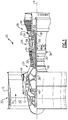
- FIG. 1 schematically illustrates a gas turbine engine 20.
- the gas turbine engine 20 is disclosed herein as a two-spool turbofan that generally incorporates a fan section 22, a compressor section 24, a combustor section 26 and a turbine section 28.
- the fan section 22 drives air along a bypass flow path B in a bypass duct defined within a nacelle 15, and also drives air along a core flow path C for compression and communication into the combustor section 26 then expansion through the turbine section 28.
- FIG. 1 schematically illustrates a gas turbine engine 20.
- the gas turbine engine 20 is disclosed herein as a two-spool turbofan that generally incorporates a fan section 22, a compressor section 24, a combustor section 26 and a turbine section 28.
- the fan section 22 drives air along a bypass flow path B in a bypass duct defined within a nacelle 15, and also drives air along a core flow path C for compression and communication into the combustor section 26 then expansion through the turbine section 28.
- FIG. 1 schematic
- the exemplary engine 20 generally includes a low speed spool 30 and a high speed spool 32 mounted for rotation about an engine central longitudinal axis A relative to an engine static structure 36 via several bearing systems 38. It should be understood that various bearing systems 38 at various locations may alternatively or additionally be provided, and the location of bearing systems 38 may be varied as appropriate to the application.
- the low speed spool 30 generally includes an inner shaft 40 that interconnects, a first (or low) pressure compressor 44 and a first (or low) pressure turbine 46.
- the inner shaft 40 is connected to the fan 42 through a speed change mechanism, which in exemplary gas turbine engine 20 is illustrated as a geared architecture 48 to drive a fan 42 at a lower speed than the low speed spool 30.
- the high speed spool 32 includes an outer shaft 50 that interconnects a second (or high) pressure compressor 52 and a second (or high) pressure turbine 54.
- a combustor 56 is arranged in exemplary gas turbine 20 between the high pressure compressor 52 and the high pressure turbine 54.
- a mid-turbine frame 57 of the engine static structure 36 may be arranged generally between the high pressure turbine 54 and the low pressure turbine 46.
- the mid-turbine frame 57 further supports bearing systems 38 in the turbine section 28.
- the inner shaft 40 and the outer shaft 50 are concentric and rotate via bearing systems 38 about the engine central longitudinal axis A which is colline
- the core airflow is compressed by the low pressure compressor 44 then the high pressure compressor 52, mixed and burned with fuel in the combustor 56, then expanded over the high pressure turbine 54 and low pressure turbine 46.
- the mid-turbine frame 57 includes airfoils 59 which are in the core airflow path C.
- the turbines 46, 54 rotationally drive the respective low speed spool 30 and high speed spool 32 in response to the expansion.
- gear system 48 may be located aft of the low pressure compressor, or aft of the combustor section 26 or even aft of turbine section 28, and fan 42 may be positioned forward or aft of the location of gear system 48.
- the engine 20 in one example is a high-bypass geared aircraft engine.
- the engine 20 bypass ratio is greater than about six, with an example embodiment being greater than about ten
- the geared architecture 48 is an epicyclic gear train, such as a planetary gear system or other gear system, with a gear reduction ratio of greater than about 2.3 and the low pressure turbine 46 has a pressure ratio that is greater than about five.
- the engine 20 bypass ratio is greater than about ten
- the fan diameter is significantly larger than that of the low pressure compressor 44
- the low pressure turbine 46 has a pressure ratio that is greater than about five.
- Low pressure turbine 46 pressure ratio is pressure measured prior to inlet of low pressure turbine 46 as related to the pressure at the outlet of the low pressure turbine 46 prior to an exhaust nozzle.
- the geared architecture 48 may be an epicycle gear train, such as a planetary gear system or other gear system, with a gear reduction ratio of greater than about 2.3:1 and less than about five. It should be understood, however, that the above parameters are only exemplary of one embodiment of a geared architecture engine and that the present invention is applicable to other gas turbine engines including direct drive turbofans.
- the fan section 22 of the engine 20 is designed for a particular flight condition -- typically cruise at about 0.8 Mach and about 35,000 feet (10,668 meters).
- the flight condition of 0.8 Mach and 35,000 ft (10,668 meters), with the engine at its best fuel consumption - also known as "bucket cruise Thrust Specific Fuel Consumption ('TSFC')" - is the industry standard parameter of lbm of fuel being burned divided by lbf of thrust the engine produces at that minimum point.
- "Low fan pressure ratio” is the pressure ratio across the fan blade alone, without a Fan Exit Guide Vane (“FEGV”) system.
- the low fan pressure ratio as disclosed herein according to one non-limiting embodiment is less than about 1.45.
- the "Low corrected fan tip speed” as disclosed herein according to one non-limiting embodiment is less than about 1150 ft / second (350.5 meters/second).
- FIG 2 illustrates a representative example of a turbine airfoil 60 used in the turbine engine 20 (see also Figure 1 ).
- the turbine airfoil 60 is a turbine vane; however, it is to be understood that, although the examples herein may be described with reference to the turbine vane, this disclosure is also applicable to turbine blades.
- the turbine airfoil 60 includes an inner or first platform 62, an outer or second platform 64, and an airfoil section 66 that radially spans between the inner and outer platforms 62/64. Terms such as “radially,” “axially,” or variations thereof are used herein to designate directionality with respect to the engine central axis A.
- the airfoil section 66 includes an airfoil outer wall 68 that delimits the profile of the airfoil section 66.
- the outer wall 68 defines a convex leading end 68a, a convex trailing end 68b, and first and second sides 68c/68d that join the leading and trailing ends 68a/68b.
- the first and second sides 68c/68d span in a longitudinal direction, denoted by axis A1, between first and second ends 68e/68f.
- the first and second ends 68e/68f are attached, respectively, to the first and second platforms 62/64.
- the first side 68c is a pressure side
- the second side 68d is a suction side.
- the convex leading end 68a and the convex trailing end 68b are convex with respect to the axial middle of the airfoil section 66. That is, the convex leading end 68a bows outwards relative to the middle of the airfoil section, and the convex trailing end bows outwards from the middle of the airfoil section 66.
- Figure 3 illustrates a sectioned view taken radially through the airfoil 60
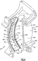
- Figure 4 illustrates a partial cutaway view of the airfoil 60
- the outer wall 68 of the airfoil section 66 circumscribes an internal core cavity 70.
- the airfoil section 66 further includes an arced rib 72 in the internal core cavity 70.
- the arced rib 72 arcs toward the convex leading end 68a.
- the arced rib 72 substantially follows the curvature of the convex leading end 68a.
- the arced rib 72 is semi-circular and the convex leading end 68a is semi-circular.
- the arced rib 72 and the convex leading end 68a each have a radius of curvature, and the radii of curvatures are equal.
- the arced rib 72 partitions the internal core cavity 70, diving the cavity 70 into a forward portion and an aft portion.
- the arced rib 72 extends from the first side 68c to the second side 68d and is solid and free of any orifices. The arced rib 72 thereby fluidly isolates the forward and aft portions of the internal core cavity 70.
- the arced rib 72 and the convex leading 68a define therebetween an arced cavity 74 in the forward portion of the internal core cavity 70.
- the arced rib 72 defines an aft margin of the arced cavity 74 and the convex leading end 68a defines a forward margin of the arced cavity 74.
- the first and second sides 68c/68d define the lateral margins of the arced cavity 74.
- the arced cavity 74 is thus also semi-circular and may thereby have a radius of curvature that is also equal to the radii of curvatures of the arced rib 72 and the convex leading end 68a.
- An arced baffle 76 is disposed in the arced cavity 74.
- the arced baffle 76 includes a forward wall 76a, an aft wall 76b, and lateral walls 76c.
- the arced baffle 76 may also include an endwall 76d near the first platform 62, while the opposite end at the second platform 64 may be open to receive cooling air. Only one of the lateral walls 76c is shown in Figure 4 , as the other is cutaway, although it is to be understood that the other lateral wall is substantially identical to the lateral wall 76c that is shown.
- the lateral walls 76c include impingement orifices 78.
- the walls 76a/76b/76c/76d of the arced baffle 76 define an interior baffle chamber 76e.
- the shape of the arced baffle 76 follows the curvatures of the arced rib 72, the convex leading end 68a, and the first and second sides 68c/68d of the airfoil wall 68.
- the overall shape of the arced baffle 76 thus corresponds to the geometry of the arced cavity 74 but is smaller than the arced cavity 74 so as to enable assembly/disassembly of the arced baffle 76 into/from the arced cavity 74.
- the arced baffle 76 is thus also semi-circular and may thereby have a radius of curvature that is also equal to the radii of curvatures of the arced rib 72 and the convex leading end 68a.
- the arced baffle 76 is in a fixed position in the arced cavity 74.
- the arced baffle 76 can be welded or otherwise affixed with the first platform 62, the second platform 64, or both.
- the fixed position which is shown in Figure 4 , there is a gap 80 surrounding the arced baffle 76.
- the gap 80 provides a stand-off distance (d) between the arced baffle 76 and the arced rib 72, between the arced baffle 76 and the convex leading end 68a, and between the arced baffle 76 and each of the first and second sides 68c/68d.
- the gap 80 is substantially constant.
- the stand-off distance (d) is substantially constant around the arced baffle 76. As will be appreciated, due to manufacturing and assembly tolerances, the gap 80 and stand-off distance (d) may vary somewhat.
- the size of the gap 80 and stand-off distance (d) are selected according to cooling performance requirements. For instance, during operation of the engine 20, cooling air, such as bleed air from the compressor section 24, is provided through the second platform 64 into the interior chamber 76e of the arced baffle 76. The cooling air flows out from the interior chamber 76e through the impingement orifices 78 and impinges on the first and second sides 68c/68d, thereby cooling the sides 68c/68d.
- the shape of the airfoil section 66 and, in particular the convex leading end 68a, are designed for aerodynamic performance.
- the convex leading end 68a challenges the use of a baffle for enhanced impingement cooling.
- a typical airfoil section for a turbine airfoil of a gas turbine engine has a straight leading end and a straight rib that define a straight leading end cavity.
- the convex leading end and the straight rib form a D-shaped cavity.
- the baffle would need to also be D-shaped. Because the D-shaped cavity is larger in the middle and narrower at the ends, it is impossible to fit a D-shaped baffle through one of the narrow ends into the cavity. A constant gap and stand-off distance is thus unobtainable.
- the arced rib 72 of the disclosed airfoil section 66 enables the use of a baffle in combination with the convex leading end 68a. Due to the arced rib 72, the shape of the arced cavity 74 is such that the arced baffle 76 can be readily inserted into, or removed from, the arced cavity 74 without undue interference from a narrow entrance constriction as with a D-shaped cavity.
- Figure 3 also demonstrates a method of either inserting the arced baffle 76 into, or removing the arced baffle 76 from, the arced cavity 74.
- the arced baffle 76 is moved along an arced path, designated at 82.
- the arced path 82 may be a continuation of the arc of the arced cavity 74.
- the arced path 82 may thus also be semi-circular and may thereby have a radius of curvature that is also equal to the radii of curvatures of the arced rib 72 and the convex leading end 68a.
- the arced baffle 76 may be inserted into, or removed from, the arced cavity 74 during an original assembly operation or during a repair or replacement process.
Landscapes
- Engineering & Computer Science (AREA)
- Mechanical Engineering (AREA)
- General Engineering & Computer Science (AREA)
- Physics & Mathematics (AREA)
- Fluid Mechanics (AREA)
- Structures Of Non-Positive Displacement Pumps (AREA)
Applications Claiming Priority (2)
| Application Number | Priority Date | Filing Date | Title |
|---|---|---|---|
| US201862757932P | 2018-11-09 | 2018-11-09 | |
| US16/532,617 US12553348B2 (en) | 2018-11-09 | 2019-08-06 | Airfoil with arced baffle |
Publications (2)
| Publication Number | Publication Date |
|---|---|
| EP3650655A1 true EP3650655A1 (fr) | 2020-05-13 |
| EP3650655B1 EP3650655B1 (fr) | 2021-06-30 |
Family
ID=68470444
Family Applications (1)
| Application Number | Title | Priority Date | Filing Date |
|---|---|---|---|
| EP19207542.2A Active EP3650655B1 (fr) | 2018-11-09 | 2019-11-06 | Profil aérodynamique, moteur à turbine à gaz et procédé d'assemblage associés |
Country Status (2)
| Country | Link |
|---|---|
| US (1) | US12553348B2 (fr) |
| EP (1) | EP3650655B1 (fr) |
Cited By (1)
| Publication number | Priority date | Publication date | Assignee | Title |
|---|---|---|---|---|
| WO2023147117A1 (fr) * | 2022-01-28 | 2023-08-03 | Raytheon Technologies Corporation | Aube refroidie à rail avant pour moteur à turbine à gaz |
Families Citing this family (3)
| Publication number | Priority date | Publication date | Assignee | Title |
|---|---|---|---|---|
| US12553348B2 (en) * | 2018-11-09 | 2026-02-17 | Rtx Corporation | Airfoil with arced baffle |
| FR3094743B1 (fr) * | 2019-04-03 | 2021-05-14 | Safran Aircraft Engines | Aube améliorée pour turbomachine |
| US12416240B2 (en) | 2022-01-28 | 2025-09-16 | Rtx Corporation | Vane forward rail for gas turbine engine assembly |
Citations (1)
| Publication number | Priority date | Publication date | Assignee | Title |
|---|---|---|---|---|
| EP1149983A2 (fr) * | 2000-04-28 | 2001-10-31 | General Electric Company | Refroidissement à pellicule pour une aube de turbine refroidie en circuit fermé |
Family Cites Families (24)
| Publication number | Priority date | Publication date | Assignee | Title |
|---|---|---|---|---|
| GB2129882B (en) * | 1982-11-10 | 1986-04-16 | Rolls Royce | Gas turbine stator vane |
| US4741667A (en) * | 1986-05-28 | 1988-05-03 | United Technologies Corporation | Stator vane |
| US5634766A (en) | 1994-08-23 | 1997-06-03 | General Electric Co. | Turbine stator vane segments having combined air and steam cooling circuits |
| US6468031B1 (en) * | 2000-05-16 | 2002-10-22 | General Electric Company | Nozzle cavity impingement/area reduction insert |
| US6561757B2 (en) * | 2001-08-03 | 2003-05-13 | General Electric Company | Turbine vane segment and impingement insert configuration for fail-safe impingement insert retention |
| GB2386926A (en) | 2002-03-27 | 2003-10-01 | Alstom | Two part impingement tube for a turbine blade or vane |
| US6742984B1 (en) * | 2003-05-19 | 2004-06-01 | General Electric Company | Divided insert for steam cooled nozzles and method for supporting and separating divided insert |
| US7086829B2 (en) * | 2004-02-03 | 2006-08-08 | General Electric Company | Film cooling for the trailing edge of a steam cooled nozzle |
| US7104756B2 (en) * | 2004-08-11 | 2006-09-12 | United Technologies Corporation | Temperature tolerant vane assembly |
| GB2428749B (en) * | 2005-08-02 | 2007-11-28 | Rolls Royce Plc | A component comprising a multiplicity of cooling passages |
| WO2009121715A1 (fr) * | 2008-03-31 | 2009-10-08 | Alstom Technology Ltd | Agencement de canaux de refroidissement à l’intérieur d’une pièce moulée creuse |
| US9403208B2 (en) * | 2010-12-30 | 2016-08-02 | United Technologies Corporation | Method and casting core for forming a landing for welding a baffle inserted in an airfoil |
| US8985278B2 (en) * | 2012-09-07 | 2015-03-24 | United Technologies Corporation | Lubrication system having segmented anti-backflow feature |
| US10329932B2 (en) * | 2015-03-02 | 2019-06-25 | United Technologies Corporation | Baffle inserts |
| FR3062675B1 (fr) * | 2017-02-07 | 2021-01-15 | Safran Helicopter Engines | Aube haute pression ventilee de turbine d'helicoptere comprenant un conduit amont et une cavite centrale de refroidissement |
| US10669861B2 (en) * | 2017-02-15 | 2020-06-02 | Raytheon Technologies Corporation | Airfoil cooling structure |
| US10982549B2 (en) * | 2017-04-17 | 2021-04-20 | General Electric Company | Stator vanes including curved trailing edges |
| US20180328187A1 (en) * | 2017-05-09 | 2018-11-15 | General Electric Company | Turbine engine with an airfoil and insert |
| US10697307B2 (en) * | 2018-01-19 | 2020-06-30 | Raytheon Technologies Corporation | Hybrid cooling schemes for airfoils of gas turbine engines |
| US11512597B2 (en) * | 2018-11-09 | 2022-11-29 | Raytheon Technologies Corporation | Airfoil with cavity lobe adjacent cooling passage network |
| US11661850B2 (en) * | 2018-11-09 | 2023-05-30 | Raytheon Technologies Corporation | Airfoil with convex sides and multi-piece baffle |
| US11377964B2 (en) * | 2018-11-09 | 2022-07-05 | Raytheon Technologies Corporation | Airfoil with cooling passage network having arced leading edge |
| US12553348B2 (en) * | 2018-11-09 | 2026-02-17 | Rtx Corporation | Airfoil with arced baffle |
| US11028702B2 (en) * | 2018-12-13 | 2021-06-08 | Raytheon Technologies Corporation | Airfoil with cooling passage network having flow guides |
-
2019
- 2019-08-06 US US16/532,617 patent/US12553348B2/en active Active
- 2019-11-06 EP EP19207542.2A patent/EP3650655B1/fr active Active
Patent Citations (1)
| Publication number | Priority date | Publication date | Assignee | Title |
|---|---|---|---|---|
| EP1149983A2 (fr) * | 2000-04-28 | 2001-10-31 | General Electric Company | Refroidissement à pellicule pour une aube de turbine refroidie en circuit fermé |
Cited By (1)
| Publication number | Priority date | Publication date | Assignee | Title |
|---|---|---|---|---|
| WO2023147117A1 (fr) * | 2022-01-28 | 2023-08-03 | Raytheon Technologies Corporation | Aube refroidie à rail avant pour moteur à turbine à gaz |
Also Published As
| Publication number | Publication date |
|---|---|
| EP3650655B1 (fr) | 2021-06-30 |
| US12553348B2 (en) | 2026-02-17 |
| US20200149401A1 (en) | 2020-05-14 |
Similar Documents
| Publication | Publication Date | Title |
|---|---|---|
| EP3734018B1 (fr) | Joint d'étanchéité pour un composant d'un moteur à turbine à gaz et procédé associé | |
| US10890079B2 (en) | Gas turbine engine arc segments with arced walls | |
| US11035236B2 (en) | Baffle for a component of a gas turbine engine | |
| EP3480430B1 (fr) | Rotor à aubage intégral pour un moteur à turbine à gaz et procédé de fabrication d'un rotor à aubage intégral pour un moteur à turbine à gaz | |
| EP3650655B1 (fr) | Profil aérodynamique, moteur à turbine à gaz et procédé d'assemblage associés | |
| EP3061910B1 (fr) | Surface portante de moteur à turbine à gaz et procédé de fabrication correspondant | |
| EP4230842A2 (fr) | Profil aérodynamique avec une nervure dotée de bras connecteurs | |
| EP3150800B1 (fr) | Déflecteur aérodynamique avec région de coin | |
| US11959397B2 (en) | Airfoil with cooling passage network having arced leading edge | |
| EP3650654B1 (fr) | Profil aérodynamique, moteur à turbine à gaz et procédé d'assemblage associés | |
| EP3650644B1 (fr) | Profil aérodynamique comportant un réseau de passage de refroidissement adjacent à un lobe de cavité | |
| EP3650646B1 (fr) | Profil aérodynamique comportant une pomme de douche à chicane et réseau de passage de refroidissement ayant une entrée arrière | |
| EP3623587B1 (fr) | Ensemble de profil aérodynamique pour moteur de turbine à gaz | |
| EP3650641B1 (fr) | Profil aérodynamique avec circuit de passage de refroidissement par des plateformes et section de profil aérodynamique | |
| US20180038236A1 (en) | Gas turbine engine stator vane baffle arrangement | |
| EP3450697B1 (fr) | Segment d'aubes de guidage et moteur à turbine à gaz associé | |
| EP3333365B1 (fr) | Stator à structure de support pour profil aérodynamique accordé | |
| EP2977557B1 (fr) | Structure d'aube refroidie et procédé de refroidissement associé | |
| EP3650643B1 (fr) | Profil aérodynamique ayant une cavité centrale s'étendant jusqu'à l'étagère de la plate-forme |
Legal Events
| Date | Code | Title | Description |
|---|---|---|---|
| PUAI | Public reference made under article 153(3) epc to a published international application that has entered the european phase |
Free format text: ORIGINAL CODE: 0009012 |
|
| STAA | Information on the status of an ep patent application or granted ep patent |
Free format text: STATUS: THE APPLICATION HAS BEEN PUBLISHED |
|
| AK | Designated contracting states |
Kind code of ref document: A1 Designated state(s): AL AT BE BG CH CY CZ DE DK EE ES FI FR GB GR HR HU IE IS IT LI LT LU LV MC MK MT NL NO PL PT RO RS SE SI SK SM TR |
|
| AX | Request for extension of the european patent |
Extension state: BA ME |
|
| STAA | Information on the status of an ep patent application or granted ep patent |
Free format text: STATUS: REQUEST FOR EXAMINATION WAS MADE |
|
| 17P | Request for examination filed |
Effective date: 20201109 |
|
| RBV | Designated contracting states (corrected) |
Designated state(s): AL AT BE BG CH CY CZ DE DK EE ES FI FR GB GR HR HU IE IS IT LI LT LU LV MC MK MT NL NO PL PT RO RS SE SI SK SM TR |
|
| RIC1 | Information provided on ipc code assigned before grant |
Ipc: F01D 9/06 20060101AFI20201125BHEP Ipc: F01D 5/18 20060101ALN20201125BHEP |
|
| GRAP | Despatch of communication of intention to grant a patent |
Free format text: ORIGINAL CODE: EPIDOSNIGR1 |
|
| STAA | Information on the status of an ep patent application or granted ep patent |
Free format text: STATUS: GRANT OF PATENT IS INTENDED |
|
| RIC1 | Information provided on ipc code assigned before grant |
Ipc: F01D 9/06 20060101AFI20201204BHEP Ipc: F01D 5/18 20060101ALN20201204BHEP |
|
| INTG | Intention to grant announced |
Effective date: 20210113 |
|
| RIN1 | Information on inventor provided before grant (corrected) |
Inventor name: PROPHETER-HINCKLEY, TRACY A. |
|
| RAP1 | Party data changed (applicant data changed or rights of an application transferred) |
Owner name: RAYTHEON TECHNOLOGIES CORPORATION |
|
| GRAS | Grant fee paid |
Free format text: ORIGINAL CODE: EPIDOSNIGR3 |
|
| GRAA | (expected) grant |
Free format text: ORIGINAL CODE: 0009210 |
|
| STAA | Information on the status of an ep patent application or granted ep patent |
Free format text: STATUS: THE PATENT HAS BEEN GRANTED |
|
| AK | Designated contracting states |
Kind code of ref document: B1 Designated state(s): AL AT BE BG CH CY CZ DE DK EE ES FI FR GB GR HR HU IE IS IT LI LT LU LV MC MK MT NL NO PL PT RO RS SE SI SK SM TR |
|
| REG | Reference to a national code |
Ref country code: CH Ref legal event code: EP |
|
| REG | Reference to a national code |
Ref country code: AT Ref legal event code: REF Ref document number: 1406523 Country of ref document: AT Kind code of ref document: T Effective date: 20210715 |
|
| REG | Reference to a national code |
Ref country code: DE Ref legal event code: R096 Ref document number: 602019005752 Country of ref document: DE |
|
| REG | Reference to a national code |
Ref country code: IE Ref legal event code: FG4D |
|
| REG | Reference to a national code |
Ref country code: LT Ref legal event code: MG9D |
|
| PG25 | Lapsed in a contracting state [announced via postgrant information from national office to epo] |
Ref country code: BG Free format text: LAPSE BECAUSE OF FAILURE TO SUBMIT A TRANSLATION OF THE DESCRIPTION OR TO PAY THE FEE WITHIN THE PRESCRIBED TIME-LIMIT Effective date: 20210930 Ref country code: FI Free format text: LAPSE BECAUSE OF FAILURE TO SUBMIT A TRANSLATION OF THE DESCRIPTION OR TO PAY THE FEE WITHIN THE PRESCRIBED TIME-LIMIT Effective date: 20210630 Ref country code: HR Free format text: LAPSE BECAUSE OF FAILURE TO SUBMIT A TRANSLATION OF THE DESCRIPTION OR TO PAY THE FEE WITHIN THE PRESCRIBED TIME-LIMIT Effective date: 20210630 |
|
| REG | Reference to a national code |
Ref country code: NL Ref legal event code: MP Effective date: 20210630 |
|
| REG | Reference to a national code |
Ref country code: AT Ref legal event code: MK05 Ref document number: 1406523 Country of ref document: AT Kind code of ref document: T Effective date: 20210630 |
|
| PG25 | Lapsed in a contracting state [announced via postgrant information from national office to epo] |
Ref country code: NO Free format text: LAPSE BECAUSE OF FAILURE TO SUBMIT A TRANSLATION OF THE DESCRIPTION OR TO PAY THE FEE WITHIN THE PRESCRIBED TIME-LIMIT Effective date: 20210930 Ref country code: LV Free format text: LAPSE BECAUSE OF FAILURE TO SUBMIT A TRANSLATION OF THE DESCRIPTION OR TO PAY THE FEE WITHIN THE PRESCRIBED TIME-LIMIT Effective date: 20210630 Ref country code: RS Free format text: LAPSE BECAUSE OF FAILURE TO SUBMIT A TRANSLATION OF THE DESCRIPTION OR TO PAY THE FEE WITHIN THE PRESCRIBED TIME-LIMIT Effective date: 20210630 Ref country code: SE Free format text: LAPSE BECAUSE OF FAILURE TO SUBMIT A TRANSLATION OF THE DESCRIPTION OR TO PAY THE FEE WITHIN THE PRESCRIBED TIME-LIMIT Effective date: 20210630 Ref country code: GR Free format text: LAPSE BECAUSE OF FAILURE TO SUBMIT A TRANSLATION OF THE DESCRIPTION OR TO PAY THE FEE WITHIN THE PRESCRIBED TIME-LIMIT Effective date: 20211001 |
|
| PG25 | Lapsed in a contracting state [announced via postgrant information from national office to epo] |
Ref country code: EE Free format text: LAPSE BECAUSE OF FAILURE TO SUBMIT A TRANSLATION OF THE DESCRIPTION OR TO PAY THE FEE WITHIN THE PRESCRIBED TIME-LIMIT Effective date: 20210630 Ref country code: ES Free format text: LAPSE BECAUSE OF FAILURE TO SUBMIT A TRANSLATION OF THE DESCRIPTION OR TO PAY THE FEE WITHIN THE PRESCRIBED TIME-LIMIT Effective date: 20210630 Ref country code: SK Free format text: LAPSE BECAUSE OF FAILURE TO SUBMIT A TRANSLATION OF THE DESCRIPTION OR TO PAY THE FEE WITHIN THE PRESCRIBED TIME-LIMIT Effective date: 20210630 Ref country code: AT Free format text: LAPSE BECAUSE OF FAILURE TO SUBMIT A TRANSLATION OF THE DESCRIPTION OR TO PAY THE FEE WITHIN THE PRESCRIBED TIME-LIMIT Effective date: 20210630 Ref country code: CZ Free format text: LAPSE BECAUSE OF FAILURE TO SUBMIT A TRANSLATION OF THE DESCRIPTION OR TO PAY THE FEE WITHIN THE PRESCRIBED TIME-LIMIT Effective date: 20210630 Ref country code: NL Free format text: LAPSE BECAUSE OF FAILURE TO SUBMIT A TRANSLATION OF THE DESCRIPTION OR TO PAY THE FEE WITHIN THE PRESCRIBED TIME-LIMIT Effective date: 20210630 Ref country code: PT Free format text: LAPSE BECAUSE OF FAILURE TO SUBMIT A TRANSLATION OF THE DESCRIPTION OR TO PAY THE FEE WITHIN THE PRESCRIBED TIME-LIMIT Effective date: 20211102 Ref country code: RO Free format text: LAPSE BECAUSE OF FAILURE TO SUBMIT A TRANSLATION OF THE DESCRIPTION OR TO PAY THE FEE WITHIN THE PRESCRIBED TIME-LIMIT Effective date: 20210630 Ref country code: SM Free format text: LAPSE BECAUSE OF FAILURE TO SUBMIT A TRANSLATION OF THE DESCRIPTION OR TO PAY THE FEE WITHIN THE PRESCRIBED TIME-LIMIT Effective date: 20210630 |
|
| PG25 | Lapsed in a contracting state [announced via postgrant information from national office to epo] |
Ref country code: PL Free format text: LAPSE BECAUSE OF FAILURE TO SUBMIT A TRANSLATION OF THE DESCRIPTION OR TO PAY THE FEE WITHIN THE PRESCRIBED TIME-LIMIT Effective date: 20210630 |
|
| REG | Reference to a national code |
Ref country code: DE Ref legal event code: R097 Ref document number: 602019005752 Country of ref document: DE |
|
| PG25 | Lapsed in a contracting state [announced via postgrant information from national office to epo] |
Ref country code: DK Free format text: LAPSE BECAUSE OF FAILURE TO SUBMIT A TRANSLATION OF THE DESCRIPTION OR TO PAY THE FEE WITHIN THE PRESCRIBED TIME-LIMIT Effective date: 20210630 |
|
| PLBE | No opposition filed within time limit |
Free format text: ORIGINAL CODE: 0009261 |
|
| STAA | Information on the status of an ep patent application or granted ep patent |
Free format text: STATUS: NO OPPOSITION FILED WITHIN TIME LIMIT |
|
| PG25 | Lapsed in a contracting state [announced via postgrant information from national office to epo] |
Ref country code: AL Free format text: LAPSE BECAUSE OF FAILURE TO SUBMIT A TRANSLATION OF THE DESCRIPTION OR TO PAY THE FEE WITHIN THE PRESCRIBED TIME-LIMIT Effective date: 20210630 |
|
| 26N | No opposition filed |
Effective date: 20220331 |
|
| PG25 | Lapsed in a contracting state [announced via postgrant information from national office to epo] |
Ref country code: MC Free format text: LAPSE BECAUSE OF FAILURE TO SUBMIT A TRANSLATION OF THE DESCRIPTION OR TO PAY THE FEE WITHIN THE PRESCRIBED TIME-LIMIT Effective date: 20210630 |
|
| PG25 | Lapsed in a contracting state [announced via postgrant information from national office to epo] |
Ref country code: LU Free format text: LAPSE BECAUSE OF NON-PAYMENT OF DUE FEES Effective date: 20211106 Ref country code: IT Free format text: LAPSE BECAUSE OF FAILURE TO SUBMIT A TRANSLATION OF THE DESCRIPTION OR TO PAY THE FEE WITHIN THE PRESCRIBED TIME-LIMIT Effective date: 20210630 Ref country code: BE Free format text: LAPSE BECAUSE OF NON-PAYMENT OF DUE FEES Effective date: 20211130 |
|
| REG | Reference to a national code |
Ref country code: BE Ref legal event code: MM Effective date: 20211130 |
|
| PG25 | Lapsed in a contracting state [announced via postgrant information from national office to epo] |
Ref country code: IE Free format text: LAPSE BECAUSE OF NON-PAYMENT OF DUE FEES Effective date: 20211106 |
|
| PG25 | Lapsed in a contracting state [announced via postgrant information from national office to epo] |
Ref country code: LT Free format text: LAPSE BECAUSE OF FAILURE TO SUBMIT A TRANSLATION OF THE DESCRIPTION OR TO PAY THE FEE WITHIN THE PRESCRIBED TIME-LIMIT Effective date: 20210630 |
|
| P01 | Opt-out of the competence of the unified patent court (upc) registered |
Effective date: 20230521 |
|
| PG25 | Lapsed in a contracting state [announced via postgrant information from national office to epo] |
Ref country code: CY Free format text: LAPSE BECAUSE OF FAILURE TO SUBMIT A TRANSLATION OF THE DESCRIPTION OR TO PAY THE FEE WITHIN THE PRESCRIBED TIME-LIMIT Effective date: 20210630 |
|
| REG | Reference to a national code |
Ref country code: CH Ref legal event code: PL |
|
| PG25 | Lapsed in a contracting state [announced via postgrant information from national office to epo] |
Ref country code: LI Free format text: LAPSE BECAUSE OF NON-PAYMENT OF DUE FEES Effective date: 20221130 Ref country code: HU Free format text: LAPSE BECAUSE OF FAILURE TO SUBMIT A TRANSLATION OF THE DESCRIPTION OR TO PAY THE FEE WITHIN THE PRESCRIBED TIME-LIMIT; INVALID AB INITIO Effective date: 20191106 Ref country code: CH Free format text: LAPSE BECAUSE OF NON-PAYMENT OF DUE FEES Effective date: 20221130 |
|
| PG25 | Lapsed in a contracting state [announced via postgrant information from national office to epo] |
Ref country code: MK Free format text: LAPSE BECAUSE OF FAILURE TO SUBMIT A TRANSLATION OF THE DESCRIPTION OR TO PAY THE FEE WITHIN THE PRESCRIBED TIME-LIMIT Effective date: 20210630 |
|
| PG25 | Lapsed in a contracting state [announced via postgrant information from national office to epo] |
Ref country code: TR Free format text: LAPSE BECAUSE OF FAILURE TO SUBMIT A TRANSLATION OF THE DESCRIPTION OR TO PAY THE FEE WITHIN THE PRESCRIBED TIME-LIMIT Effective date: 20210630 |
|
| PG25 | Lapsed in a contracting state [announced via postgrant information from national office to epo] |
Ref country code: MT Free format text: LAPSE BECAUSE OF FAILURE TO SUBMIT A TRANSLATION OF THE DESCRIPTION OR TO PAY THE FEE WITHIN THE PRESCRIBED TIME-LIMIT Effective date: 20210630 |
|
| REG | Reference to a national code |
Ref country code: DE Ref legal event code: R081 Ref document number: 602019005752 Country of ref document: DE Owner name: RTX CORPORATION (N.D.GES.D. STAATES DELAWARE),, US Free format text: FORMER OWNER: RAYTHEON TECHNOLOGIES CORPORATION, FARMINGTON, CT, US |
|
| PGFP | Annual fee paid to national office [announced via postgrant information from national office to epo] |
Ref country code: DE Payment date: 20251022 Year of fee payment: 7 |
|
| PGFP | Annual fee paid to national office [announced via postgrant information from national office to epo] |
Ref country code: GB Payment date: 20251023 Year of fee payment: 7 |
|
| PGFP | Annual fee paid to national office [announced via postgrant information from national office to epo] |
Ref country code: FR Payment date: 20251023 Year of fee payment: 7 |