EP3650715B1 - Capuchon eme pour la prévention de l'écoulement d'huile d'étanchéité non durcie - Google Patents
Capuchon eme pour la prévention de l'écoulement d'huile d'étanchéité non durcie Download PDFInfo
- Publication number
- EP3650715B1 EP3650715B1 EP19204019.4A EP19204019A EP3650715B1 EP 3650715 B1 EP3650715 B1 EP 3650715B1 EP 19204019 A EP19204019 A EP 19204019A EP 3650715 B1 EP3650715 B1 EP 3650715B1
- Authority
- EP
- European Patent Office
- Prior art keywords
- wall member
- cavity
- cap
- uncured sealant
- containment apparatus
- Prior art date
- Legal status (The legal status is an assumption and is not a legal conclusion. Google has not performed a legal analysis and makes no representation as to the accuracy of the status listed.)
- Active
Links
Images

Classifications
-
- F—MECHANICAL ENGINEERING; LIGHTING; HEATING; WEAPONS; BLASTING
- F16—ENGINEERING ELEMENTS AND UNITS; GENERAL MEASURES FOR PRODUCING AND MAINTAINING EFFECTIVE FUNCTIONING OF MACHINES OR INSTALLATIONS; THERMAL INSULATION IN GENERAL
- F16B—DEVICES FOR FASTENING OR SECURING CONSTRUCTIONAL ELEMENTS OR MACHINE PARTS TOGETHER, e.g. NAILS, BOLTS, CIRCLIPS, CLAMPS, CLIPS OR WEDGES; JOINTS OR JOINTING
- F16B37/00—Nuts or like thread-engaging members
- F16B37/14—Cap nuts; Nut caps or bolt caps
-
- H—ELECTRICITY
- H01—ELECTRIC ELEMENTS
- H01B—CABLES; CONDUCTORS; INSULATORS; SELECTION OF MATERIALS FOR THEIR CONDUCTIVE, INSULATING OR DIELECTRIC PROPERTIES
- H01B17/00—Insulators or insulating bodies characterised by their form
- H01B17/56—Insulating bodies
-
- B—PERFORMING OPERATIONS; TRANSPORTING
- B64—AIRCRAFT; AVIATION; COSMONAUTICS
- B64D—EQUIPMENT FOR FITTING IN OR TO AIRCRAFT; FLIGHT SUITS; PARACHUTES; ARRANGEMENT OR MOUNTING OF POWER PLANTS OR PROPULSION TRANSMISSIONS IN AIRCRAFT
- B64D45/00—Aircraft indicators or protectors not otherwise provided for
- B64D45/02—Lightning protectors; Static dischargers
-
- F—MECHANICAL ENGINEERING; LIGHTING; HEATING; WEAPONS; BLASTING
- F16—ENGINEERING ELEMENTS AND UNITS; GENERAL MEASURES FOR PRODUCING AND MAINTAINING EFFECTIVE FUNCTIONING OF MACHINES OR INSTALLATIONS; THERMAL INSULATION IN GENERAL
- F16B—DEVICES FOR FASTENING OR SECURING CONSTRUCTIONAL ELEMENTS OR MACHINE PARTS TOGETHER, e.g. NAILS, BOLTS, CIRCLIPS, CLAMPS, CLIPS OR WEDGES; JOINTS OR JOINTING
- F16B33/00—Features common to bolt and nut
- F16B33/004—Sealing; Insulation
-
- F—MECHANICAL ENGINEERING; LIGHTING; HEATING; WEAPONS; BLASTING
- F16—ENGINEERING ELEMENTS AND UNITS; GENERAL MEASURES FOR PRODUCING AND MAINTAINING EFFECTIVE FUNCTIONING OF MACHINES OR INSTALLATIONS; THERMAL INSULATION IN GENERAL
- F16B—DEVICES FOR FASTENING OR SECURING CONSTRUCTIONAL ELEMENTS OR MACHINE PARTS TOGETHER, e.g. NAILS, BOLTS, CIRCLIPS, CLAMPS, CLIPS OR WEDGES; JOINTS OR JOINTING
- F16B37/00—Nuts or like thread-engaging members
- F16B37/04—Devices for fastening nuts to surfaces, e.g. sheets, plates
- F16B37/044—Nut cages
Definitions
- This disclosure relates to an electrical insulation containment apparatus which electrically insulates a metallic fastener from transmitting electrical current or sparks into a vicinity of the location of the metallic fastener upon an occurrence of an electromagnetic effect ("EME") or lightning strike event and more particularly to an electrical insulating cap member containing sealant which encloses the metallic fastener within the cap member and a structure surface from which the metallic fastener extends.
- EME electromagnetic effect
- Electrical insulation containment apparatus such as cap members made of cured sealant material, which also contains sealant, have been used to cover, enclose and electrically insulate an end portion of a metallic fastener assembly extending from a structure surface.
- the metallic fastener assembly can include a wide range of fasteners wherein the end portion can include, for example, a nut and a threaded end portion of a stud or bolt or a bolt head along with washers as well as other such configurations.
- the cap member confines the end portion of the metallic fastener within the cap member and the structure surface from which the metallic fastener extends.
- a portion of the uncured sealant, which is positioned within the cap member, is often displaced by the end portion of the metallic fastener being inserted into the cap member during installation of the cap member.
- the uncured sealant which is displaced is squeezed out between the edge of the cap member and the structure surface to which the edge of the cap member is to abut with the cap member being installed.
- the uncured sealant from the cap member is positioned on the structure surface and positioned about the cap member.
- the unsecured sealant expelled or squeezed out of the cap member is then smoothed out about the containment cap to ensure proper sealing of the cap member.
- the smoothing process of the unsecured sealant is tedious and time consuming.
- the sealant, which is positioned outside of the cap member is also subjected to visual inspection, adhesion testing and post adhesion inspections.
- Document WO 2014/118510 A1 discloses a method of providing a sealed cavity around one end of a fastener passing through a structure.
- a cap assembly is provided.
- the cap assembly has a base terminating at a base rim; a plunger fitted over the base, the plunger comprising a plunger body, and a skirt extending outwardly from the plunger body, the skirt terminating at a skirt rim.
- a bead of sealant material is provided in a pocket defined by the skirt.
- the plunger or the base comprises a cap with an end wall opposite the skirt rim or the base rim.
- the structure or fastener is engaged with the base rim, with the bead of sealant material engaging the skirt in the pocket and set back from the structure as the base rim engages the structure or the fastener.
- the plunger is pushed towards the structure so that the plunger slides axially relative to the base from a first position to a second position, the skirt of the sliding plunger pushing the bead of sealant material in the pocket into engagement with the structure so that the sealant material flows to form a seal against the structure and the cap provides the sealed cavity around the one end of the fastener. Finally the sealant is cured so that the sealant adheres the plunger to the structure.
- Document EP 3059170 A1 discloses a cap for forming a sealed cavity around an end of a fastener.
- the cap has a cap body with an annular base terminating at an inner cap rim which surrounds an opening into a central cavity and lies in an inner cap plane around a majority of a circumference of the annular base.
- a skirt provides an annular pocket between the skirt and the annular base.
- the skirt has a first part which is integrally formed with the cap body from a first material and terminates at an edge, and a second part which is formed from a second material and extends from the edge of the first part of the skirt to a skirt rim which lies in or below the inner cap plane around a majority of a circumference of the skirt.
- the second part of the skirt is attached to the edge of the first part of the skirt by a joint comprising a male part received in an annular groove which runs round the circumference of the skirt.
- the first material has a first elastic modulus and the second material has a second elastic modulus which is lower than the first elastic modulus.
- An inlet hole in the skirt is in fluid communication with the annular pocket to permit a flow of sealing material through the skirt via the inlet hole into the annular pocket.
- the skirt forms a continuous annular wall with no holes through the annular skirt in fluid communication with the annular pocket other than the inlet hole.
- Document US 2014/0261956 A1 discloses a method and apparatus for sealing a fastener element.
- a structure may be positioned over a seal cap that has been adhered and sealed to the fastener element.
- a number of projections associated with the structure may be moved along an interface formed between the seal cap and an object in which the fastener element has been installed such that the number of projections removes at least a portion of excess material around the seal cap while moving along the interface between the seal cap and the object.
- the present disclosure relates to a containment apparatus for enclosing a metallic fastener extending through a structure having the features disclosed at claim 1.
- the dependent claims 2-9 outline advantageous aspects of the apparatus.
- the present disclosure relates to a method of installing a containment apparatus for enclosing a metallic fastener extending from a structure including the steps defined at claim 10.
- the dependent claims outline advantageous ways of carrying out the method.
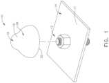
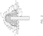
- Cap member 16 of containment apparatus 10 includes first wall member 18, which defines first cavity 20 and first end 22, wherein first end 22 defines first opening 24 providing access into first cavity 20 for at least a portion of metallic fastener 12.
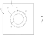
- Second wall member 26 is secured to and extends from exterior surface 28 of first wall member 18. Second wall member 26 extends spaced apart from and along first wall member 18 to first end 32. Second wall member 26 can be connected to first wall member 18 as separate parts or can be integrally molded as a single part. Second wall member 26 surrounds first wall member 18, as seen in FIG.
- first wall member 18 and second wall member 26 form second cavity 30 positioned between first wall member 18 and second wall member 26.
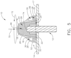
- First end 22 of first wall member 18 and first end 32 of second wall member 26 are coplanar with one another positioned within plane P as seen in FIG. 5 .
- This configuration of cap member 16 provides for confining uncured sealant so as not to become squeeze out uncured sealant from cap member 16 during installation. In avoiding uncured sealant exiting cap member 16, substantial labor and cost can be avoided in not having to smooth out exited uncured sealant.
- second cavity 30 confines uncured sealant which has been displaced out of first cavity 20 from the insertion of metallic fastener 12 into first cavity 20 during installation. The uncured sealant confined within second cavity 30, when cured, provides additional securement of cap member 16 to structure 14 that is provided by cured sealant positioned within first cavity 20.
- Cap member 16 can be constructed in one of a variety of fabrication processes such as for example various molding techniques or additive manufacturing and from one of a wide variety of materials such as for example thermoplastic or thermoset materials.
- Thermoplastic materials can include, for example, such compositions as acrylonitrile butadiene styrene, polyactic acid, polyvinyl alcohol, polycarbonate and polyetherimide or other like compositions.
- Thermoset materials can include, for example, such compositions as polysulfide, polythioether, polyurethane, epoxy, acrylate or polyimide or other like compositions.
- first end 22 in this example includes flat surface 34.
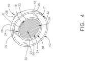
- Flat surface 34 of first end 22 extends in circular direction C, as seen in FIG. 4 , defining first opening 24 having circular configuration 38.
- Flat surface 34 provides for reliable confinement of metallic fastener 12 with cap member 16 positioned against a flat surface of structure 14 and the circular configuration provides ease in manufacturing of cap member 16 provides a versatile configuration in engaging different shaped metallic fasteners 12.
- First end 32 of second wall member 26 includes, in this example, flat surface 40.
- Flat surface 40 provides for a reliable confinement for second cavity 30 in preventing uncured sealant from exiting second cavity 30 and be positioned outside of cap member 16.
- Flat surface 40 of first end 32 of second wall member 26 and flat surface 34 of first end 22 of first wall member 18 are spaced apart from one another and flat surface 40 of first end 32 of second wall member 26 surrounds flat surface 34 of first end 22 of first wall member 18.
- Flat surface 40 of second wall member 26 extends in circular direction C'.
- Flat surfaces 34 and 40 provide a concentric configuration, as seen in FIG. 4 .
- the spaced surrounding of second wall member 26 about first wall member 18 provides second cavity 30 for securing and storing uncured sealant within second cavity 30 and prevent uncured sealant initially positioned within first cavity 20 to exit cap member 16.
- first wall member 18 and second wall member 26 is integral with one another, which provides for ease in manufacturing and reduction in cost with respect to assembling.
- First wall member 18 and second wall member 26 are joined together at location M spaced apart from first end 22 of first wall member 18 and first end 32 of second wall member 26.
- This configuration of first wall member 18 and second wall member 26 provides for accommodating space within second cavity 30 to receive uncured sealant exiting first cavity 20 and preventing uncured sealant exiting second cavity 30.
- Interior surface 42 of second wall member 26 extends in curvilinear direction 44 from first end 32 of second wall member 26. At least a portion 45 of an interior surface 46 of first wall member 18 extends in a curvilinear direction 47.
- the curvilinear surfaces of the respective wall members provide ease in manufacturing of cap member 16.
- Exterior surface 52 of second wall member 26 extends in curvilinear direction 53 from exterior surface 28 of first wall member 18 provides for a smooth continuous outer surface which provides for ease in manufacturing of cap member 16.
- method 62 of installing a containment apparatus 10 for enclosing metallic fastener 12 extending from structure 14 surface 17 includes step 64 of placing uncured sealant 66 into first cavity 20 of cap member 16, which includes first wall member 18, which defines first cavity 20 and first end 22, as seen in FIG. 4 .
- Uncured sealant 66 can include one of a wide variety of chemical compositions such as for example, polysulfide, polythioether, polyurethane, epoxy, acrylate or polyimide.
- First end 22 defines first opening 24 providing access into first cavity 20 for at least a portion of metallic fastener 12.
- Second wall member 26 is secured to and extends from exterior surface 28 of first wall member 18, as seen in FIG. 2 .
- Second wall member 26 extends spaced apart from and extends along first wall member 18 to first end 32 of second wall member 26. Second wall member 26 surrounds first wall member 18 such that first wall member 18 and second wall member 26 form second cavity 30 positioned between first wall member 18 and second wall member 26. First end 22 of first wall member 18 and first end 32 of second wall member 26 are coplanar with one another with being positioned in plane P as seen in FIG. 5 .
- Method 62 further includes step 68 of inserting at least a portion of metallic fastener 12 into first cavity 20, as also seen in FIG. 5 .
- Method 62 provides for installation of cap member 16, such that uncured sealant 66 is confined within cap member 16 during installation and does not result in uncured sealant 66 within cap member 16 becoming squeeze out uncured sealant 66 from cap member 16 during installation.
- second cavity 30 confines uncured sealant 66 which has come out of first cavity 20 from the insertion of metallic fastener 12 and into second cavity 30 during installation.
- Uncured sealant 66 confined within second cavity 30, when cured, provides additional securement of cap member 16 to structure 14 to that which is provided by uncured sealant 66 positioned within first cavity 20.
- Method 62 further includes a step of exerting a force onto cap member 16 in direction 70 toward metallic fastener 12.
- the step of exerting the force onto the cap member 16 further includes turning cap member 16 in direction 72 about central axis 74 of cap member 16.
- the application of force toward metallic fastener 12 and turning of cap member 16 provides for a smoothing and thinning out of uncured sealant 66 exiting first cavity 20 with metallic fastener 12 being inserted into first cavity 20.
- Method 62 further includes a step of moving uncured sealant 66, as seen in FIG. 5 , between first end 22 of first wall member 18 and structure 14.
- This moving of uncured sealant 66 is facilitated with smoothing and squeezing out of uncured sealant 66 positioned between first end 22 of first wall member 18 and surface 17 of structure 14 with turning of cap member 16 and with exerting the force onto cap member 16.
- Moving of uncured sealant 66 between first end 22 of wall member 18 allows the displaced uncured sealant from first cavity 20 to move into second cavity 30 and provide ease in installing cap member 16 onto metallic fastener 12 with experiencing little resistance with uncured sealant flowing through and between first end 22 and structure 14.
- the step of moving further includes positioning uncured sealant 66 which has moved beyond first wall member 18 in alignment with second cavity 30 with first end 22 of first wall member 18 and first end 32 of second wall member 26 positioned spaced apart from structure 14. Positioning uncured sealant 66 in alignment with second cavity 30 provides for ease in confinement of uncured sealant 66 within second cavity 30 when installing cap member 16.
- Method 62 further includes a step of positioning first end 22 of first wall member 18 and first end 32 of second wall member 26 in abutting relationship with structure 14 with uncured sealant 66 positioned within second cavity 30. With abutting of first end 22 and first end 32 against structure 14, uncured sealant 66 aligned with second cavity 30 is then confined within second cavity 30 and sealed from exiting cap member 16.
- uncured sealant 66 that has been squeezed out from first wall member 18 is thereby confined within second cavity 30 by second wall member 26 blocking uncured sealant 66 from squeezing out beyond second wall member 26.
- Confinement of uncured sealant 66 within cap member 16, as mentioned, reduces labor and cost in not having to smooth out uncured sealant 66 and prevents an occurrence of uncured sealant 66 being positioned on structure 14 outside of cap member 16 and within an environment which can be sensitive to uncured sealant 66.
- Uncured sealant 66 positioned within first cavity 20 when cured, secures cap member 16 to structure 14 and uncured sealant 66 positioned within second cavity 30, when cured, further secures cap member 16 to structure 14.
Landscapes
- Engineering & Computer Science (AREA)
- General Engineering & Computer Science (AREA)
- Mechanical Engineering (AREA)
- Aviation & Aerospace Engineering (AREA)
- Gasket Seals (AREA)
- Building Environments (AREA)
- Casings For Electric Apparatus (AREA)
- Connection Of Plates (AREA)
Claims (15)
- Appareil d'isolement (10) pour le confinement d'une attache métallique (12) s'étendant à travers une structure (14), comprenant :
un organe formant capuchon (16) et un agent d'étanchéité non durci (66) comprenant :un premier organe formant paroi (18) qui définit une première cavité (20) et une première extrémité (22), dans lequel la première extrémité (22) définit une première ouverture (24) adaptée pour fournir un accès dans la première cavité (20) pour au moins une partie de l'attache métallique (14), l'agent d'étanchéité non durci (66) étant reçu dans la première cavité (20) ;un second organe formant paroi (26) est fixé à une surface extérieure (28) du premier organe formant paroi (18) et s'étend à partir de celle-ci, dans lequel :le second organe formant paroi (26) s'étend en étant espacé du premier organe formant paroi (18) et le long de celui-ci jusqu'à une première extrémité (32) ; etle second organe formant paroi (26) entoure le premier organe formant paroi (18) de sorte que le premier organe formant paroi (18) et le second organe formant paroi (26) forment une seconde cavité (30) positionnée entre le premier organe formant paroi (18) et le second organe formant paroi (26), l'agent d'étanchéité non durci (66) étant reçu dans la seconde cavité (30) ; etla première extrémité (22) du premier organe formant paroi (18) et la première extrémité (32) du second organe formant paroi (26) sont coplanaires l'une avec l'autre, l'agent d'étanchéité non durci (66) positionné au sein de la première cavité (20), lorsqu'il est durci, fixant l'organe formant capuchon (16) à la structure (14) et l'agent d'étanchéité non durci (66) positionné au sein de la seconde cavité (30), lorsqu'il est durci, fixant davantage l'organe formant capuchon (16) à la structure. - Appareil d'isolement (10) selon la revendication 1, dans lequel la première extrémité (22) du premier organe formant paroi (18) comprend une surface plane (34).
- Appareil d'isolement (10) selon la revendication 2, dans lequel la surface plane (34) de la première extrémité (22) s'étend dans une direction circulaire (C) définissant une première ouverture (24) ayant une configuration circulaire (38).
- Appareil d'isolement (10) selon l'une quelconque des revendications 1 à 3, dans lequel le premier organe formant paroi (18) et le second organe formant paroi (26) forment une pièce unique.
- Appareil d'isolement (10) selon l'une quelconque des revendications 1 à 4, dans lequel le premier organe formant paroi (18) et le second organe formant paroi (26) se rejoignent à un emplacement (M) espacé de la première extrémité (22) du premier organe formant paroi (18) et de la première extrémité (32) du second organe formant paroi (26).
- Appareil d'isolement (10) selon l'une quelconque des revendications 1 à 5, dans lequel une surface extérieure (52) du second organe formant paroi (26) s'étend dans une direction curviligne (53) à partir de la surface extérieure (28) du premier organe formant paroi (18).
- Appareil d'isolement (10) selon l'une quelconque des revendications 1 à 6, dans lequel la première extrémité (32) du second organe formant paroi (26) comprend une surface plane (40).
- Appareil d'isolement (10) selon la revendication 7, dans lequel la surface plane (40) de la première extrémité (32) du second organe formant paroi (26) et la surface plane (34) de la première extrémité (22) du premier organe formant paroi (18) sont espacées l'une de l'autre.
- Appareil d'isolement (10) selon la revendication 8, dans lequel la surface plane (40) de la première extrémité (32) du second organe formant paroi (26) entoure la surface plane (34) de la première extrémité (22) du premier organe formant paroi (18).
- Procédé (62) d'installation d'un appareil d'isolement (10) pour le confinement d'une attache métallique (12) s'étendant à partir d'une structure (14), comprenant les étapes de :
le placement (64) d'un agent d'étanchéité non durci (66) dans une première cavité (20) d'un organe formant capuchon (16), qui comprend :un premier organe formant paroi (18) qui définit la première cavité (20) et une première extrémité (22), dans lequel la première extrémité (22) définit une première ouverture (24) fournissant un accès dans la première cavité (20) pour au moins une partie de l'attache métallique (12) ;un second organe formant paroi (26) est fixé à une surface extérieure (28) du premier organe formant paroi (18) et s'étend à partir de celle-ci, dans lequel :le second organe formant paroi (26) s'étend en étant espacé du premier organe formant paroi (18) et s'étend le long de celui-ci jusqu'à une première extrémité (32) du second organe formant paroi (26) ;le second organe formant paroi (26) entoure le premier organe formant paroi (18) de sorte que le premier organe formant paroi (18) et le second organe formant paroi (26) forment une seconde cavité (30) positionnée entre le premier organe formant paroi (18) et le second organe formant paroi (26) ; etla première extrémité (22) du premier organe formant paroi (18) et la première extrémité (32) du second organe formant paroi (26) sont coplanaires l'une avec l'autre ; etl'insertion (68) d'au moins une partie de l'attache métallique (12) dans la première cavité (20). - Procédé (62) selon la revendication 10, comportant en outre une étape d'application d'une force sur l'organe formant capuchon dans une direction (70) allant vers l'attache métallique (12).
- Procédé (62) selon la revendication 11, dans lequel l'étape d'application de la force sur l'organe formant capuchon (16) comporte en outre la rotation de l'organe formant capuchon (16) autour d'un axe central (74) de l'organe formant capuchon (16).
- Procédé (62) selon l'une quelconque des revendications 10 à 12, comportant en outre une étape de déplacement de l'agent d'étanchéité non durci (66) entre la première extrémité (22) du premier organe formant paroi (18) et la structure (14).
- Procédé (62) selon la revendication 13, dans lequel l'étape de déplacement comporte en outre le positionnement de l'agent d'étanchéité (66) qui s'est déplacé au-delà du premier organe formant paroi (18) en alignement avec la seconde cavité (30) avec la première extrémité (22) du premier organe formant paroi (18) et la première extrémité (32) du second organe formant paroi (26) positionnées en étant espacées de la structure (14).
- Procédé (62) selon l'une quelconque des revendications 10 à 14, comportant en outre une étape de positionnement de la première extrémité (22) du premier organe formant paroi (18) et la première extrémité (32) du second organe formant paroi (26) en relation de butée sur la structure (14) avec un agent d'étanchéité non durci (66) positionné au sein de la seconde cavité (30).
Applications Claiming Priority (1)
| Application Number | Priority Date | Filing Date | Title |
|---|---|---|---|
| US16/185,500 US11248647B2 (en) | 2018-11-09 | 2018-11-09 | EME cap for preventing uncured sealant squeeze out |
Publications (2)
| Publication Number | Publication Date |
|---|---|
| EP3650715A1 EP3650715A1 (fr) | 2020-05-13 |
| EP3650715B1 true EP3650715B1 (fr) | 2024-03-06 |
Family
ID=68296079
Family Applications (1)
| Application Number | Title | Priority Date | Filing Date |
|---|---|---|---|
| EP19204019.4A Active EP3650715B1 (fr) | 2018-11-09 | 2019-10-18 | Capuchon eme pour la prévention de l'écoulement d'huile d'étanchéité non durcie |
Country Status (5)
| Country | Link |
|---|---|
| US (1) | US11248647B2 (fr) |
| EP (1) | EP3650715B1 (fr) |
| JP (1) | JP7455553B2 (fr) |
| CN (1) | CN111180148B (fr) |
| CA (1) | CA3059452C (fr) |
Families Citing this family (2)
| Publication number | Priority date | Publication date | Assignee | Title |
|---|---|---|---|---|
| JP2020020387A (ja) * | 2018-07-31 | 2020-02-06 | 三菱重工業株式会社 | キャップシール、これを備えた締結構造、及びキャップシールの装着方法 |
| EP4001124B1 (fr) * | 2020-11-19 | 2024-02-07 | The Boeing Company | Ensemble couvercle étanche pour un aéronef ou une autre structure et son procédé d'assemblage |
Family Cites Families (71)
| Publication number | Priority date | Publication date | Assignee | Title |
|---|---|---|---|---|
| US1368637A (en) | 1919-08-16 | 1921-02-15 | Robert R Mcfarland | Nut-lock |
| US1868084A (en) | 1931-06-29 | 1932-07-19 | Old Dominion Iron & Steel Work | Stay bolt |
| US2109035A (en) * | 1935-07-29 | 1938-02-22 | Bronson Reel Company | Jewel mount |
| DE1085586B (de) | 1956-02-16 | 1960-07-21 | Bbc Brown Boveri & Cie | Schutzkapsel fuer Schrauben-, Bolzen- oder Nietkoepfe in Anwendung als Schutzvorrichtung gegen Spannungs- und Lichtbogenueberschlaege |
| US3241427A (en) * | 1963-06-27 | 1966-03-22 | Borg Warner | Bolt cap unit |
| GB1314331A (en) | 1969-05-14 | 1973-04-18 | Nat Res Dev | Equipment protection |
| US3618444A (en) * | 1969-05-16 | 1971-11-09 | Usm Corp | Corrosion resistant fasteners |
| US4013190A (en) | 1972-05-10 | 1977-03-22 | Mcdonnell Douglas Corporation | Flame arresting and explosion attenuating system |
| US4519974A (en) | 1983-08-12 | 1985-05-28 | Ltv Aerospace And Defense Company | Method and apparatus for applying a sealant to exposed fasteners |
| FI863590A7 (fi) | 1985-09-13 | 1987-03-14 | Confon Ag | Liukuestelaite erityisesti ilmalla täytettyjä kulkuneuvonrenkaita varten jää- ja lumipinnoilla sekä sovite ruuvinkantoja ja sentapaisia varten. |
| US4636446A (en) | 1985-11-15 | 1987-01-13 | Cheng Kwang Storage Battery Co., Ltd. | Stopper structure for storage battery container |
| US4630168A (en) | 1985-12-16 | 1986-12-16 | The Boeing Company | Lightning protection fastener |
| US4826380A (en) | 1988-01-19 | 1989-05-02 | Ltv Aerospace & Defense Company | Pre-cast sealant dome and method |
| US4850778A (en) | 1988-07-27 | 1989-07-25 | Trw, Inc. | Push-on fastener |
| JPH083701Y2 (ja) | 1990-04-03 | 1996-01-31 | 株式会社エポゾール | ボルト・ナット用キャップ |
| US5108853A (en) | 1990-12-20 | 1992-04-28 | Exide Corporation | Submersible and flame retardant battery vent plug |
| US5752794A (en) | 1996-11-04 | 1998-05-19 | Chrysler Corporation | Fastener retention system for a wheel cover of a vehicle |
| US6102128A (en) | 1997-03-13 | 2000-08-15 | Bridgeman; William M. | Fire-resistant blanket |
| US6053683A (en) | 1999-02-04 | 2000-04-25 | Cabiran; Michel Lewis | Threaded seal cap for a connector |
| JP2001165138A (ja) | 1999-12-08 | 2001-06-19 | Nippon Doboku Shizai Kk | ロックボルトの防錆装置 |
| FR2802268B1 (fr) | 1999-12-09 | 2002-02-22 | Joint Francais | Dispositifs d'application d'un mastic d'etancheite, support de stockage, de transport et d'utilisation de ces dispositifs et leurs utilisations |
| US6318942B1 (en) | 2000-08-16 | 2001-11-20 | Mckechnie Vehicle Components (Usa), Inc. | Lug cap having retention detents |
| JP2002266832A (ja) | 2001-03-12 | 2002-09-18 | Masahiko Nema | ナンバープレートのボルト用キャップ |
| ITTO20010468A1 (it) | 2001-05-18 | 2002-11-18 | Ruspa S P A | Elemento di copertura per organo di collegamento filettato. |
| CN1280273C (zh) | 2003-11-05 | 2006-10-18 | 天津和美生物技术有限公司 | 合成多奈哌齐及其衍生物的方法 |
| KR20060045211A (ko) * | 2004-11-12 | 2006-05-17 | 유창훈 | 볼트 및 너트 부식방지용 캡 |
| US7755876B2 (en) | 2005-07-01 | 2010-07-13 | The Boeing Company | Fastening assembly including washer for sealing the assembly for lightning strike protection in composite structures |
| ES2286955B1 (es) | 2006-05-31 | 2008-10-16 | Valentin Ortiz Teruel | Lonas cortafuegos multicapa. |
| US7599164B2 (en) | 2006-12-07 | 2009-10-06 | The Boeing Company | Lightning protection system for aircraft composite structure |
| US7918081B2 (en) | 2006-12-19 | 2011-04-05 | United Technologies Corporation | Flame prevention device |
| ES2342641B1 (es) | 2007-11-15 | 2011-04-25 | Airbus España S.L. | Dispositivo de proteccion contra descargas electricas en elementos defijacion con carga elevada. |
| KR101086609B1 (ko) | 2009-06-01 | 2011-11-23 | 현대자동차주식회사 | 카울 크로스바 마운팅 조립체 |
| DE102010016782B4 (de) | 2010-05-04 | 2016-12-08 | R.Stahl Schaltgeräte GmbH | Druckentlastungsvorrichtung für druckfest gekapselte Gehäuse |
| EP2673193B1 (fr) * | 2011-02-10 | 2018-07-11 | Airbus Operations Limited | Capuchon pour former une cavité hermétiquement scellée autour d'une fermeture |
| US8616868B2 (en) | 2011-02-28 | 2013-12-31 | Physical Systems, Inc. | Sealant mold fixture for a domed cap |
| US8388293B2 (en) | 2011-02-28 | 2013-03-05 | Physical Systems, Inc. | Insulated and sealed cap for a fastener component |
| KR101254138B1 (ko) | 2011-03-16 | 2013-04-15 | 진재호 | 볼트 및 너트 이중 보호 캡 |
| JP5611097B2 (ja) | 2011-03-30 | 2014-10-22 | 三菱航空機株式会社 | 耐雷防爆用ファスナ |
| US20130223951A1 (en) | 2011-04-28 | 2013-08-29 | Masahiro Bessho | Cap and fixing structure using the same |
| US20130007650A1 (en) | 2011-06-07 | 2013-01-03 | Beta Fluid Systems, Inc. | Systems and methods for providing a control system for aircraft refueling trucks |
| US8840740B2 (en) | 2011-06-24 | 2014-09-23 | The Boeing Company | Apparatus for preventing spark propagation |
| US8717735B2 (en) | 2011-12-14 | 2014-05-06 | The Boeing Company | Seal with energy-absorbing filler and method of manufacture |
| JP5931458B2 (ja) | 2012-01-17 | 2016-06-08 | 三菱航空機株式会社 | 耐雷ファスナ、耐雷ファスナの装着方法 |
| DE102012202053A1 (de) | 2012-02-10 | 2013-08-14 | Airbus Operations Gmbh | Verbindungsanordnung sowie Verfahren |
| CN103388614A (zh) * | 2012-05-07 | 2013-11-13 | 华锐风电科技(集团)股份有限公司 | 一种地脚螺栓保护帽 |
| WO2013178985A1 (fr) | 2012-05-31 | 2013-12-05 | Airbus Operations Limited | Cache-écrou injectable |
| US9133874B2 (en) | 2012-06-15 | 2015-09-15 | Oz-Post International, LLC | Mounting hardware |
| US9377047B2 (en) | 2013-06-14 | 2016-06-28 | Oz-Post International, LLC | Through bolted connection hardware |
| GB201214579D0 (en) | 2012-08-15 | 2012-09-26 | Airbus Operations Ltd | Flanged cap for forming sealed cavity around fastener |
| GB201305459D0 (en) | 2013-01-30 | 2013-05-08 | Short Brothers Plc | Electrical protector |
| GB201301704D0 (en) | 2013-01-31 | 2013-03-20 | Airbus Operations Ltd | Cap assembly |
| US9295367B2 (en) | 2013-03-12 | 2016-03-29 | The Boeing Company | Tool for removing sealant around a seal cap |
| GB2514171B (en) | 2013-05-16 | 2015-11-25 | Airbus Operations Ltd | Injectable nut cap |
| US20160131179A1 (en) | 2013-06-11 | 2016-05-12 | Systems And Materials Research Corporation | Sealant cap |
| US9188226B2 (en) | 2013-07-15 | 2015-11-17 | The Boeing Company | Apparatus for installing a seal cap |
| GB2516835B (en) | 2013-07-31 | 2015-11-04 | Airbus Operations Ltd | Cap to accommodate washers |
| KR20160044495A (ko) | 2013-08-21 | 2016-04-25 | 에어버스 오퍼레이션즈 리미티드 | 주입식 밀봉재를 구비하는 캡 |
| GB2520774A (en) * | 2013-12-02 | 2015-06-03 | Airbus Operations Ltd | Cap with injected sealant |
| DE102013109260A1 (de) | 2013-08-27 | 2015-03-05 | R.Stahl Schaltgeräte GmbH | Gehäuseteil für ein explosionsgeschütztes Gehäuse mit einem porösen Körper |
| US9618029B2 (en) | 2013-09-23 | 2017-04-11 | The Boeing Company | Systems and methods for use in covering a portion of a fastener protruding from a surface |
| US9541118B2 (en) | 2013-09-23 | 2017-01-10 | The Boeing Company | Systems and methods for use in covering a portion of a fastener protruding from a surface |
| GB2523125B (en) | 2014-02-13 | 2016-10-19 | Airbus Operations Ltd | Lobed nut cap |
| JP6324784B2 (ja) | 2014-03-24 | 2018-05-16 | 三菱重工業株式会社 | キャップ、およびキャップの成形型、キャップを用いた固定構造部、キャップの装着方法 |
| GB2535518A (en) | 2015-02-20 | 2016-08-24 | Airbus Operations Ltd | Cap with injected sealant |
| US10512805B2 (en) | 2015-07-21 | 2019-12-24 | The Boeing Company | Ignition-quenching systems, apparatuses, and methods |
| US10246866B2 (en) * | 2016-05-04 | 2019-04-02 | Charles Hugh Junca | Toilet fastening assembly and method |
| US10179640B2 (en) | 2016-08-24 | 2019-01-15 | The Boeing Company | Wing and method of manufacturing |
| GB2557962A (en) * | 2016-12-20 | 2018-07-04 | Airbus Operations Ltd | Cap for a fastener |
| US10655667B2 (en) | 2017-09-28 | 2020-05-19 | The Boeing Company | Rapid installation thermoplastic EME protection cap |
| GB2572376A (en) | 2018-03-28 | 2019-10-02 | Airbus Operations Ltd | Cap with sealant flow path |
| US10729043B1 (en) * | 2019-04-17 | 2020-07-28 | The Boeing Company | Vacuum cap seal installation |
-
2018
- 2018-11-09 US US16/185,500 patent/US11248647B2/en active Active
-
2019
- 2019-10-18 CA CA3059452A patent/CA3059452C/fr active Active
- 2019-10-18 EP EP19204019.4A patent/EP3650715B1/fr active Active
- 2019-11-04 CN CN201911063602.0A patent/CN111180148B/zh active Active
- 2019-11-07 JP JP2019202104A patent/JP7455553B2/ja active Active
Also Published As
| Publication number | Publication date |
|---|---|
| CN111180148B (zh) | 2023-07-14 |
| CA3059452C (fr) | 2023-10-17 |
| JP2020098028A (ja) | 2020-06-25 |
| CA3059452A1 (fr) | 2020-05-09 |
| CN111180148A (zh) | 2020-05-19 |
| US20200149579A1 (en) | 2020-05-14 |
| US11248647B2 (en) | 2022-02-15 |
| EP3650715A1 (fr) | 2020-05-13 |
| JP7455553B2 (ja) | 2024-03-26 |
Similar Documents
| Publication | Publication Date | Title |
|---|---|---|
| EP3560838B1 (fr) | Rondelle d'ancrage pour un système de capuchon de protection | |
| US11130591B2 (en) | Lobed nut cap | |
| EP3560839B1 (fr) | Écrou d'ancrage pour un système de capuchon de protection eme | |
| EP3599172B1 (fr) | Tête de boulon d'ancrage pour un système de capuchon de protection eme | |
| EP2996941B1 (fr) | Cache-écrou injectable | |
| EP3036163B1 (fr) | Capuchon avec mastic d'étanchéité injecté | |
| EP3650715B1 (fr) | Capuchon eme pour la prévention de l'écoulement d'huile d'étanchéité non durcie | |
| CN104364158B (zh) | 可注射螺帽盖 | |
| GB2533317A (en) | Spark containment cap | |
| EP2986509B1 (fr) | Coiffe injectable | |
| EP3656680B1 (fr) | Système de capuchon de protection d'effet électromagnétique doté d'un mécanisme d'extrusion de matériau d'étanchéité de poussée | |
| WO2014118510A1 (fr) | Ensemble capuchon de fixation | |
| CN113366229A (zh) | 火花抑制帽 | |
| WO2014118509A1 (fr) | Ensemble capuchon | |
| EP3741682B1 (fr) | Système de capuchon de protection contre les effets électromagnétiques de fusion multi-composants |
Legal Events
| Date | Code | Title | Description |
|---|---|---|---|
| PUAI | Public reference made under article 153(3) epc to a published international application that has entered the european phase |
Free format text: ORIGINAL CODE: 0009012 |
|
| STAA | Information on the status of an ep patent application or granted ep patent |
Free format text: STATUS: THE APPLICATION HAS BEEN PUBLISHED |
|
| AK | Designated contracting states |
Kind code of ref document: A1 Designated state(s): AL AT BE BG CH CY CZ DE DK EE ES FI FR GB GR HR HU IE IS IT LI LT LU LV MC MK MT NL NO PL PT RO RS SE SI SK SM TR |
|
| AX | Request for extension of the european patent |
Extension state: BA ME |
|
| STAA | Information on the status of an ep patent application or granted ep patent |
Free format text: STATUS: REQUEST FOR EXAMINATION WAS MADE |
|
| 17P | Request for examination filed |
Effective date: 20201111 |
|
| RBV | Designated contracting states (corrected) |
Designated state(s): AL AT BE BG CH CY CZ DE DK EE ES FI FR GB GR HR HU IE IS IT LI LT LU LV MC MK MT NL NO PL PT RO RS SE SI SK SM TR |
|
| STAA | Information on the status of an ep patent application or granted ep patent |
Free format text: STATUS: EXAMINATION IS IN PROGRESS |
|
| 17Q | First examination report despatched |
Effective date: 20220803 |
|
| RAP3 | Party data changed (applicant data changed or rights of an application transferred) |
Owner name: THE BOEING COMPANY |
|
| GRAP | Despatch of communication of intention to grant a patent |
Free format text: ORIGINAL CODE: EPIDOSNIGR1 |
|
| STAA | Information on the status of an ep patent application or granted ep patent |
Free format text: STATUS: GRANT OF PATENT IS INTENDED |
|
| INTG | Intention to grant announced |
Effective date: 20231018 |
|
| GRAS | Grant fee paid |
Free format text: ORIGINAL CODE: EPIDOSNIGR3 |
|
| GRAA | (expected) grant |
Free format text: ORIGINAL CODE: 0009210 |
|
| STAA | Information on the status of an ep patent application or granted ep patent |
Free format text: STATUS: THE PATENT HAS BEEN GRANTED |
|
| AK | Designated contracting states |
Kind code of ref document: B1 Designated state(s): AL AT BE BG CH CY CZ DE DK EE ES FI FR GB GR HR HU IE IS IT LI LT LU LV MC MK MT NL NO PL PT RO RS SE SI SK SM TR |
|
| P01 | Opt-out of the competence of the unified patent court (upc) registered |
Effective date: 20240131 |
|
| REG | Reference to a national code |
Ref country code: CH Ref legal event code: EP |
|
| REG | Reference to a national code |
Ref country code: DE Ref legal event code: R096 Ref document number: 602019047660 Country of ref document: DE |
|
| REG | Reference to a national code |
Ref country code: IE Ref legal event code: FG4D |
|
| REG | Reference to a national code |
Ref country code: LT Ref legal event code: MG9D |
|
| PG25 | Lapsed in a contracting state [announced via postgrant information from national office to epo] |
Ref country code: LT Free format text: LAPSE BECAUSE OF FAILURE TO SUBMIT A TRANSLATION OF THE DESCRIPTION OR TO PAY THE FEE WITHIN THE PRESCRIBED TIME-LIMIT Effective date: 20240306 |
|
| REG | Reference to a national code |
Ref country code: NL Ref legal event code: MP Effective date: 20240306 |
|
| PG25 | Lapsed in a contracting state [announced via postgrant information from national office to epo] |
Ref country code: GR Free format text: LAPSE BECAUSE OF FAILURE TO SUBMIT A TRANSLATION OF THE DESCRIPTION OR TO PAY THE FEE WITHIN THE PRESCRIBED TIME-LIMIT Effective date: 20240607 |
|
| PG25 | Lapsed in a contracting state [announced via postgrant information from national office to epo] |
Ref country code: RS Free format text: LAPSE BECAUSE OF FAILURE TO SUBMIT A TRANSLATION OF THE DESCRIPTION OR TO PAY THE FEE WITHIN THE PRESCRIBED TIME-LIMIT Effective date: 20240606 Ref country code: HR Free format text: LAPSE BECAUSE OF FAILURE TO SUBMIT A TRANSLATION OF THE DESCRIPTION OR TO PAY THE FEE WITHIN THE PRESCRIBED TIME-LIMIT Effective date: 20240306 |
|
| PG25 | Lapsed in a contracting state [announced via postgrant information from national office to epo] |
Ref country code: ES Free format text: LAPSE BECAUSE OF FAILURE TO SUBMIT A TRANSLATION OF THE DESCRIPTION OR TO PAY THE FEE WITHIN THE PRESCRIBED TIME-LIMIT Effective date: 20240306 |
|
| PG25 | Lapsed in a contracting state [announced via postgrant information from national office to epo] |
Ref country code: RS Free format text: LAPSE BECAUSE OF FAILURE TO SUBMIT A TRANSLATION OF THE DESCRIPTION OR TO PAY THE FEE WITHIN THE PRESCRIBED TIME-LIMIT Effective date: 20240606 Ref country code: NO Free format text: LAPSE BECAUSE OF FAILURE TO SUBMIT A TRANSLATION OF THE DESCRIPTION OR TO PAY THE FEE WITHIN THE PRESCRIBED TIME-LIMIT Effective date: 20240606 Ref country code: LT Free format text: LAPSE BECAUSE OF FAILURE TO SUBMIT A TRANSLATION OF THE DESCRIPTION OR TO PAY THE FEE WITHIN THE PRESCRIBED TIME-LIMIT Effective date: 20240306 Ref country code: HR Free format text: LAPSE BECAUSE OF FAILURE TO SUBMIT A TRANSLATION OF THE DESCRIPTION OR TO PAY THE FEE WITHIN THE PRESCRIBED TIME-LIMIT Effective date: 20240306 Ref country code: GR Free format text: LAPSE BECAUSE OF FAILURE TO SUBMIT A TRANSLATION OF THE DESCRIPTION OR TO PAY THE FEE WITHIN THE PRESCRIBED TIME-LIMIT Effective date: 20240607 Ref country code: FI Free format text: LAPSE BECAUSE OF FAILURE TO SUBMIT A TRANSLATION OF THE DESCRIPTION OR TO PAY THE FEE WITHIN THE PRESCRIBED TIME-LIMIT Effective date: 20240306 Ref country code: ES Free format text: LAPSE BECAUSE OF FAILURE TO SUBMIT A TRANSLATION OF THE DESCRIPTION OR TO PAY THE FEE WITHIN THE PRESCRIBED TIME-LIMIT Effective date: 20240306 Ref country code: BG Free format text: LAPSE BECAUSE OF FAILURE TO SUBMIT A TRANSLATION OF THE DESCRIPTION OR TO PAY THE FEE WITHIN THE PRESCRIBED TIME-LIMIT Effective date: 20240306 |
|
| REG | Reference to a national code |
Ref country code: AT Ref legal event code: MK05 Ref document number: 1663780 Country of ref document: AT Kind code of ref document: T Effective date: 20240306 |
|
| PG25 | Lapsed in a contracting state [announced via postgrant information from national office to epo] |
Ref country code: SE Free format text: LAPSE BECAUSE OF FAILURE TO SUBMIT A TRANSLATION OF THE DESCRIPTION OR TO PAY THE FEE WITHIN THE PRESCRIBED TIME-LIMIT Effective date: 20240306 Ref country code: LV Free format text: LAPSE BECAUSE OF FAILURE TO SUBMIT A TRANSLATION OF THE DESCRIPTION OR TO PAY THE FEE WITHIN THE PRESCRIBED TIME-LIMIT Effective date: 20240306 |
|
| PG25 | Lapsed in a contracting state [announced via postgrant information from national office to epo] |
Ref country code: NL Free format text: LAPSE BECAUSE OF FAILURE TO SUBMIT A TRANSLATION OF THE DESCRIPTION OR TO PAY THE FEE WITHIN THE PRESCRIBED TIME-LIMIT Effective date: 20240306 |
|
| PG25 | Lapsed in a contracting state [announced via postgrant information from national office to epo] |
Ref country code: NL Free format text: LAPSE BECAUSE OF FAILURE TO SUBMIT A TRANSLATION OF THE DESCRIPTION OR TO PAY THE FEE WITHIN THE PRESCRIBED TIME-LIMIT Effective date: 20240306 |
|
| PG25 | Lapsed in a contracting state [announced via postgrant information from national office to epo] |
Ref country code: IS Free format text: LAPSE BECAUSE OF FAILURE TO SUBMIT A TRANSLATION OF THE DESCRIPTION OR TO PAY THE FEE WITHIN THE PRESCRIBED TIME-LIMIT Effective date: 20240706 |
|
| PG25 | Lapsed in a contracting state [announced via postgrant information from national office to epo] |
Ref country code: SM Free format text: LAPSE BECAUSE OF FAILURE TO SUBMIT A TRANSLATION OF THE DESCRIPTION OR TO PAY THE FEE WITHIN THE PRESCRIBED TIME-LIMIT Effective date: 20240306 Ref country code: PT Free format text: LAPSE BECAUSE OF FAILURE TO SUBMIT A TRANSLATION OF THE DESCRIPTION OR TO PAY THE FEE WITHIN THE PRESCRIBED TIME-LIMIT Effective date: 20240708 |
|
| PG25 | Lapsed in a contracting state [announced via postgrant information from national office to epo] |
Ref country code: EE Free format text: LAPSE BECAUSE OF FAILURE TO SUBMIT A TRANSLATION OF THE DESCRIPTION OR TO PAY THE FEE WITHIN THE PRESCRIBED TIME-LIMIT Effective date: 20240306 Ref country code: CZ Free format text: LAPSE BECAUSE OF FAILURE TO SUBMIT A TRANSLATION OF THE DESCRIPTION OR TO PAY THE FEE WITHIN THE PRESCRIBED TIME-LIMIT Effective date: 20240306 |
|
| PG25 | Lapsed in a contracting state [announced via postgrant information from national office to epo] |
Ref country code: AT Free format text: LAPSE BECAUSE OF FAILURE TO SUBMIT A TRANSLATION OF THE DESCRIPTION OR TO PAY THE FEE WITHIN THE PRESCRIBED TIME-LIMIT Effective date: 20240306 |
|
| PG25 | Lapsed in a contracting state [announced via postgrant information from national office to epo] |
Ref country code: PL Free format text: LAPSE BECAUSE OF FAILURE TO SUBMIT A TRANSLATION OF THE DESCRIPTION OR TO PAY THE FEE WITHIN THE PRESCRIBED TIME-LIMIT Effective date: 20240306 |
|
| PG25 | Lapsed in a contracting state [announced via postgrant information from national office to epo] |
Ref country code: SK Free format text: LAPSE BECAUSE OF FAILURE TO SUBMIT A TRANSLATION OF THE DESCRIPTION OR TO PAY THE FEE WITHIN THE PRESCRIBED TIME-LIMIT Effective date: 20240306 |
|
| PG25 | Lapsed in a contracting state [announced via postgrant information from national office to epo] |
Ref country code: SM Free format text: LAPSE BECAUSE OF FAILURE TO SUBMIT A TRANSLATION OF THE DESCRIPTION OR TO PAY THE FEE WITHIN THE PRESCRIBED TIME-LIMIT Effective date: 20240306 Ref country code: SK Free format text: LAPSE BECAUSE OF FAILURE TO SUBMIT A TRANSLATION OF THE DESCRIPTION OR TO PAY THE FEE WITHIN THE PRESCRIBED TIME-LIMIT Effective date: 20240306 Ref country code: RO Free format text: LAPSE BECAUSE OF FAILURE TO SUBMIT A TRANSLATION OF THE DESCRIPTION OR TO PAY THE FEE WITHIN THE PRESCRIBED TIME-LIMIT Effective date: 20240306 Ref country code: PT Free format text: LAPSE BECAUSE OF FAILURE TO SUBMIT A TRANSLATION OF THE DESCRIPTION OR TO PAY THE FEE WITHIN THE PRESCRIBED TIME-LIMIT Effective date: 20240708 Ref country code: PL Free format text: LAPSE BECAUSE OF FAILURE TO SUBMIT A TRANSLATION OF THE DESCRIPTION OR TO PAY THE FEE WITHIN THE PRESCRIBED TIME-LIMIT Effective date: 20240306 Ref country code: IS Free format text: LAPSE BECAUSE OF FAILURE TO SUBMIT A TRANSLATION OF THE DESCRIPTION OR TO PAY THE FEE WITHIN THE PRESCRIBED TIME-LIMIT Effective date: 20240706 Ref country code: EE Free format text: LAPSE BECAUSE OF FAILURE TO SUBMIT A TRANSLATION OF THE DESCRIPTION OR TO PAY THE FEE WITHIN THE PRESCRIBED TIME-LIMIT Effective date: 20240306 Ref country code: CZ Free format text: LAPSE BECAUSE OF FAILURE TO SUBMIT A TRANSLATION OF THE DESCRIPTION OR TO PAY THE FEE WITHIN THE PRESCRIBED TIME-LIMIT Effective date: 20240306 Ref country code: AT Free format text: LAPSE BECAUSE OF FAILURE TO SUBMIT A TRANSLATION OF THE DESCRIPTION OR TO PAY THE FEE WITHIN THE PRESCRIBED TIME-LIMIT Effective date: 20240306 |
|
| PG25 | Lapsed in a contracting state [announced via postgrant information from national office to epo] |
Ref country code: IT Free format text: LAPSE BECAUSE OF FAILURE TO SUBMIT A TRANSLATION OF THE DESCRIPTION OR TO PAY THE FEE WITHIN THE PRESCRIBED TIME-LIMIT Effective date: 20240306 |
|
| REG | Reference to a national code |
Ref country code: DE Ref legal event code: R097 Ref document number: 602019047660 Country of ref document: DE |
|
| PG25 | Lapsed in a contracting state [announced via postgrant information from national office to epo] |
Ref country code: IT Free format text: LAPSE BECAUSE OF FAILURE TO SUBMIT A TRANSLATION OF THE DESCRIPTION OR TO PAY THE FEE WITHIN THE PRESCRIBED TIME-LIMIT Effective date: 20240306 |
|
| PLBE | No opposition filed within time limit |
Free format text: ORIGINAL CODE: 0009261 |
|
| STAA | Information on the status of an ep patent application or granted ep patent |
Free format text: STATUS: NO OPPOSITION FILED WITHIN TIME LIMIT |
|
| PG25 | Lapsed in a contracting state [announced via postgrant information from national office to epo] |
Ref country code: DK Free format text: LAPSE BECAUSE OF FAILURE TO SUBMIT A TRANSLATION OF THE DESCRIPTION OR TO PAY THE FEE WITHIN THE PRESCRIBED TIME-LIMIT Effective date: 20240306 |
|
| PG25 | Lapsed in a contracting state [announced via postgrant information from national office to epo] |
Ref country code: DK Free format text: LAPSE BECAUSE OF FAILURE TO SUBMIT A TRANSLATION OF THE DESCRIPTION OR TO PAY THE FEE WITHIN THE PRESCRIBED TIME-LIMIT Effective date: 20240306 |
|
| 26N | No opposition filed |
Effective date: 20241209 |
|
| PG25 | Lapsed in a contracting state [announced via postgrant information from national office to epo] |
Ref country code: SI Free format text: LAPSE BECAUSE OF FAILURE TO SUBMIT A TRANSLATION OF THE DESCRIPTION OR TO PAY THE FEE WITHIN THE PRESCRIBED TIME-LIMIT Effective date: 20240306 |
|
| REG | Reference to a national code |
Ref country code: CH Ref legal event code: PL |
|
| PG25 | Lapsed in a contracting state [announced via postgrant information from national office to epo] |
Ref country code: MC Free format text: LAPSE BECAUSE OF FAILURE TO SUBMIT A TRANSLATION OF THE DESCRIPTION OR TO PAY THE FEE WITHIN THE PRESCRIBED TIME-LIMIT Effective date: 20240306 |
|
| PG25 | Lapsed in a contracting state [announced via postgrant information from national office to epo] |
Ref country code: LU Free format text: LAPSE BECAUSE OF NON-PAYMENT OF DUE FEES Effective date: 20241018 Ref country code: BE Free format text: LAPSE BECAUSE OF NON-PAYMENT OF DUE FEES Effective date: 20241031 |
|
| PG25 | Lapsed in a contracting state [announced via postgrant information from national office to epo] |
Ref country code: CH Free format text: LAPSE BECAUSE OF NON-PAYMENT OF DUE FEES Effective date: 20241031 |
|
| REG | Reference to a national code |
Ref country code: BE Ref legal event code: MM Effective date: 20241031 |
|
| PG25 | Lapsed in a contracting state [announced via postgrant information from national office to epo] |
Ref country code: IE Free format text: LAPSE BECAUSE OF NON-PAYMENT OF DUE FEES Effective date: 20241018 |
|
| PGFP | Annual fee paid to national office [announced via postgrant information from national office to epo] |
Ref country code: DE Payment date: 20251029 Year of fee payment: 7 |
|
| PGFP | Annual fee paid to national office [announced via postgrant information from national office to epo] |
Ref country code: GB Payment date: 20251027 Year of fee payment: 7 |
|
| PGFP | Annual fee paid to national office [announced via postgrant information from national office to epo] |
Ref country code: FR Payment date: 20251027 Year of fee payment: 7 |
|
| PG25 | Lapsed in a contracting state [announced via postgrant information from national office to epo] |
Ref country code: CY Free format text: LAPSE BECAUSE OF FAILURE TO SUBMIT A TRANSLATION OF THE DESCRIPTION OR TO PAY THE FEE WITHIN THE PRESCRIBED TIME-LIMIT; INVALID AB INITIO Effective date: 20191018 |
|
| PG25 | Lapsed in a contracting state [announced via postgrant information from national office to epo] |
Ref country code: HU Free format text: LAPSE BECAUSE OF FAILURE TO SUBMIT A TRANSLATION OF THE DESCRIPTION OR TO PAY THE FEE WITHIN THE PRESCRIBED TIME-LIMIT; INVALID AB INITIO Effective date: 20191018 |