EP3650722A1 - Élément coulissant - Google Patents
Élément coulissant Download PDFInfo
- Publication number
- EP3650722A1 EP3650722A1 EP18828562.1A EP18828562A EP3650722A1 EP 3650722 A1 EP3650722 A1 EP 3650722A1 EP 18828562 A EP18828562 A EP 18828562A EP 3650722 A1 EP3650722 A1 EP 3650722A1
- Authority
- EP
- European Patent Office
- Prior art keywords
- peripheral edge
- sliding
- edge part
- dimple
- concave part
- Prior art date
- Legal status (The legal status is an assumption and is not a legal conclusion. Google has not performed a legal analysis and makes no representation as to the accuracy of the status listed.)
- Granted
Links
Images



Classifications
-
- F—MECHANICAL ENGINEERING; LIGHTING; HEATING; WEAPONS; BLASTING
- F16—ENGINEERING ELEMENTS AND UNITS; GENERAL MEASURES FOR PRODUCING AND MAINTAINING EFFECTIVE FUNCTIONING OF MACHINES OR INSTALLATIONS; THERMAL INSULATION IN GENERAL
- F16C—SHAFTS; FLEXIBLE SHAFTS; ELEMENTS OR CRANKSHAFT MECHANISMS; ROTARY BODIES OTHER THAN GEARING ELEMENTS; BEARINGS
- F16C33/00—Parts of bearings; Special methods for making bearings or parts thereof
- F16C33/02—Parts of sliding-contact bearings
- F16C33/04—Brasses; Bushes; Linings
- F16C33/06—Sliding surface mainly made of metal
- F16C33/10—Construction relative to lubrication
- F16C33/1025—Construction relative to lubrication with liquid, e.g. oil, as lubricant
- F16C33/103—Construction relative to lubrication with liquid, e.g. oil, as lubricant retained in or near the bearing
-
- F—MECHANICAL ENGINEERING; LIGHTING; HEATING; WEAPONS; BLASTING
- F16—ENGINEERING ELEMENTS AND UNITS; GENERAL MEASURES FOR PRODUCING AND MAINTAINING EFFECTIVE FUNCTIONING OF MACHINES OR INSTALLATIONS; THERMAL INSULATION IN GENERAL
- F16C—SHAFTS; FLEXIBLE SHAFTS; ELEMENTS OR CRANKSHAFT MECHANISMS; ROTARY BODIES OTHER THAN GEARING ELEMENTS; BEARINGS
- F16C33/00—Parts of bearings; Special methods for making bearings or parts thereof
- F16C33/02—Parts of sliding-contact bearings
- F16C33/04—Brasses; Bushes; Linings
- F16C33/06—Sliding surface mainly made of metal
- F16C33/12—Structural composition; Use of special materials or surface treatments, e.g. for rust-proofing
- F16C33/128—Porous bearings, e.g. bushes of sintered alloy
-
- F—MECHANICAL ENGINEERING; LIGHTING; HEATING; WEAPONS; BLASTING
- F16—ENGINEERING ELEMENTS AND UNITS; GENERAL MEASURES FOR PRODUCING AND MAINTAINING EFFECTIVE FUNCTIONING OF MACHINES OR INSTALLATIONS; THERMAL INSULATION IN GENERAL
- F16C—SHAFTS; FLEXIBLE SHAFTS; ELEMENTS OR CRANKSHAFT MECHANISMS; ROTARY BODIES OTHER THAN GEARING ELEMENTS; BEARINGS
- F16C17/00—Sliding-contact bearings for exclusively rotary movement
- F16C17/04—Sliding-contact bearings for exclusively rotary movement for axial load only
-
- F—MECHANICAL ENGINEERING; LIGHTING; HEATING; WEAPONS; BLASTING
- F16—ENGINEERING ELEMENTS AND UNITS; GENERAL MEASURES FOR PRODUCING AND MAINTAINING EFFECTIVE FUNCTIONING OF MACHINES OR INSTALLATIONS; THERMAL INSULATION IN GENERAL
- F16C—SHAFTS; FLEXIBLE SHAFTS; ELEMENTS OR CRANKSHAFT MECHANISMS; ROTARY BODIES OTHER THAN GEARING ELEMENTS; BEARINGS
- F16C17/00—Sliding-contact bearings for exclusively rotary movement
- F16C17/04—Sliding-contact bearings for exclusively rotary movement for axial load only
- F16C17/045—Sliding-contact bearings for exclusively rotary movement for axial load only with grooves in the bearing surface to generate hydrodynamic pressure, e.g. spiral groove thrust bearings
-
- F—MECHANICAL ENGINEERING; LIGHTING; HEATING; WEAPONS; BLASTING
- F16—ENGINEERING ELEMENTS AND UNITS; GENERAL MEASURES FOR PRODUCING AND MAINTAINING EFFECTIVE FUNCTIONING OF MACHINES OR INSTALLATIONS; THERMAL INSULATION IN GENERAL
- F16C—SHAFTS; FLEXIBLE SHAFTS; ELEMENTS OR CRANKSHAFT MECHANISMS; ROTARY BODIES OTHER THAN GEARING ELEMENTS; BEARINGS
- F16C33/00—Parts of bearings; Special methods for making bearings or parts thereof
- F16C33/02—Parts of sliding-contact bearings
- F16C33/04—Brasses; Bushes; Linings
- F16C33/06—Sliding surface mainly made of metal
- F16C33/10—Construction relative to lubrication
- F16C33/1025—Construction relative to lubrication with liquid, e.g. oil, as lubricant
- F16C33/106—Details of distribution or circulation inside the bearings, e.g. details of the bearing surfaces to affect flow or pressure of the liquid
-
- F—MECHANICAL ENGINEERING; LIGHTING; HEATING; WEAPONS; BLASTING
- F16—ENGINEERING ELEMENTS AND UNITS; GENERAL MEASURES FOR PRODUCING AND MAINTAINING EFFECTIVE FUNCTIONING OF MACHINES OR INSTALLATIONS; THERMAL INSULATION IN GENERAL
- F16C—SHAFTS; FLEXIBLE SHAFTS; ELEMENTS OR CRANKSHAFT MECHANISMS; ROTARY BODIES OTHER THAN GEARING ELEMENTS; BEARINGS
- F16C33/00—Parts of bearings; Special methods for making bearings or parts thereof
- F16C33/02—Parts of sliding-contact bearings
- F16C33/04—Brasses; Bushes; Linings
- F16C33/06—Sliding surface mainly made of metal
- F16C33/10—Construction relative to lubrication
- F16C33/1025—Construction relative to lubrication with liquid, e.g. oil, as lubricant
- F16C33/106—Details of distribution or circulation inside the bearings, e.g. details of the bearing surfaces to affect flow or pressure of the liquid
- F16C33/1065—Grooves on a bearing surface for distributing or collecting the liquid
-
- F—MECHANICAL ENGINEERING; LIGHTING; HEATING; WEAPONS; BLASTING
- F16—ENGINEERING ELEMENTS AND UNITS; GENERAL MEASURES FOR PRODUCING AND MAINTAINING EFFECTIVE FUNCTIONING OF MACHINES OR INSTALLATIONS; THERMAL INSULATION IN GENERAL
- F16C—SHAFTS; FLEXIBLE SHAFTS; ELEMENTS OR CRANKSHAFT MECHANISMS; ROTARY BODIES OTHER THAN GEARING ELEMENTS; BEARINGS
- F16C33/00—Parts of bearings; Special methods for making bearings or parts thereof
- F16C33/02—Parts of sliding-contact bearings
- F16C33/04—Brasses; Bushes; Linings
- F16C33/06—Sliding surface mainly made of metal
- F16C33/10—Construction relative to lubrication
- F16C33/1025—Construction relative to lubrication with liquid, e.g. oil, as lubricant
- F16C33/106—Details of distribution or circulation inside the bearings, e.g. details of the bearing surfaces to affect flow or pressure of the liquid
- F16C33/107—Grooves for generating pressure
-
- F—MECHANICAL ENGINEERING; LIGHTING; HEATING; WEAPONS; BLASTING
- F16—ENGINEERING ELEMENTS AND UNITS; GENERAL MEASURES FOR PRODUCING AND MAINTAINING EFFECTIVE FUNCTIONING OF MACHINES OR INSTALLATIONS; THERMAL INSULATION IN GENERAL
- F16C—SHAFTS; FLEXIBLE SHAFTS; ELEMENTS OR CRANKSHAFT MECHANISMS; ROTARY BODIES OTHER THAN GEARING ELEMENTS; BEARINGS
- F16C33/00—Parts of bearings; Special methods for making bearings or parts thereof
- F16C33/02—Parts of sliding-contact bearings
- F16C33/04—Brasses; Bushes; Linings
- F16C33/06—Sliding surface mainly made of metal
- F16C33/14—Special methods of manufacture; Running-in
-
- F—MECHANICAL ENGINEERING; LIGHTING; HEATING; WEAPONS; BLASTING
- F16—ENGINEERING ELEMENTS AND UNITS; GENERAL MEASURES FOR PRODUCING AND MAINTAINING EFFECTIVE FUNCTIONING OF MACHINES OR INSTALLATIONS; THERMAL INSULATION IN GENERAL
- F16C—SHAFTS; FLEXIBLE SHAFTS; ELEMENTS OR CRANKSHAFT MECHANISMS; ROTARY BODIES OTHER THAN GEARING ELEMENTS; BEARINGS
- F16C33/00—Parts of bearings; Special methods for making bearings or parts thereof
- F16C33/02—Parts of sliding-contact bearings
- F16C33/04—Brasses; Bushes; Linings
- F16C33/24—Brasses; Bushes; Linings with different areas of the sliding surface consisting of different materials
-
- F—MECHANICAL ENGINEERING; LIGHTING; HEATING; WEAPONS; BLASTING
- F16—ENGINEERING ELEMENTS AND UNITS; GENERAL MEASURES FOR PRODUCING AND MAINTAINING EFFECTIVE FUNCTIONING OF MACHINES OR INSTALLATIONS; THERMAL INSULATION IN GENERAL
- F16C—SHAFTS; FLEXIBLE SHAFTS; ELEMENTS OR CRANKSHAFT MECHANISMS; ROTARY BODIES OTHER THAN GEARING ELEMENTS; BEARINGS
- F16C33/00—Parts of bearings; Special methods for making bearings or parts thereof
- F16C33/72—Sealings
- F16C33/74—Sealings of sliding-contact bearings
-
- F—MECHANICAL ENGINEERING; LIGHTING; HEATING; WEAPONS; BLASTING
- F16—ENGINEERING ELEMENTS AND UNITS; GENERAL MEASURES FOR PRODUCING AND MAINTAINING EFFECTIVE FUNCTIONING OF MACHINES OR INSTALLATIONS; THERMAL INSULATION IN GENERAL
- F16J—PISTONS; CYLINDERS; SEALINGS
- F16J15/00—Sealings
- F16J15/16—Sealings between relatively-moving surfaces
- F16J15/34—Sealings between relatively-moving surfaces with slip-ring pressed against a more or less radial face on one member
- F16J15/3404—Sealings between relatively-moving surfaces with slip-ring pressed against a more or less radial face on one member and characterised by parts or details relating to lubrication, cooling or venting of the seal
- F16J15/3408—Sealings between relatively-moving surfaces with slip-ring pressed against a more or less radial face on one member and characterised by parts or details relating to lubrication, cooling or venting of the seal at least one ring having an uneven slipping surface
- F16J15/3412—Sealings between relatively-moving surfaces with slip-ring pressed against a more or less radial face on one member and characterised by parts or details relating to lubrication, cooling or venting of the seal at least one ring having an uneven slipping surface with cavities
-
- F—MECHANICAL ENGINEERING; LIGHTING; HEATING; WEAPONS; BLASTING
- F16—ENGINEERING ELEMENTS AND UNITS; GENERAL MEASURES FOR PRODUCING AND MAINTAINING EFFECTIVE FUNCTIONING OF MACHINES OR INSTALLATIONS; THERMAL INSULATION IN GENERAL
- F16J—PISTONS; CYLINDERS; SEALINGS
- F16J15/00—Sealings
- F16J15/16—Sealings between relatively-moving surfaces
- F16J15/34—Sealings between relatively-moving surfaces with slip-ring pressed against a more or less radial face on one member
- F16J15/3404—Sealings between relatively-moving surfaces with slip-ring pressed against a more or less radial face on one member and characterised by parts or details relating to lubrication, cooling or venting of the seal
- F16J15/3408—Sealings between relatively-moving surfaces with slip-ring pressed against a more or less radial face on one member and characterised by parts or details relating to lubrication, cooling or venting of the seal at least one ring having an uneven slipping surface
- F16J15/3424—Sealings between relatively-moving surfaces with slip-ring pressed against a more or less radial face on one member and characterised by parts or details relating to lubrication, cooling or venting of the seal at least one ring having an uneven slipping surface with microcavities
-
- F—MECHANICAL ENGINEERING; LIGHTING; HEATING; WEAPONS; BLASTING
- F16—ENGINEERING ELEMENTS AND UNITS; GENERAL MEASURES FOR PRODUCING AND MAINTAINING EFFECTIVE FUNCTIONING OF MACHINES OR INSTALLATIONS; THERMAL INSULATION IN GENERAL
- F16J—PISTONS; CYLINDERS; SEALINGS
- F16J15/00—Sealings
- F16J15/16—Sealings between relatively-moving surfaces
- F16J15/34—Sealings between relatively-moving surfaces with slip-ring pressed against a more or less radial face on one member
- F16J15/36—Sealings between relatively-moving surfaces with slip-ring pressed against a more or less radial face on one member connected by a diaphragm or bellow to the other member
-
- F—MECHANICAL ENGINEERING; LIGHTING; HEATING; WEAPONS; BLASTING
- F16—ENGINEERING ELEMENTS AND UNITS; GENERAL MEASURES FOR PRODUCING AND MAINTAINING EFFECTIVE FUNCTIONING OF MACHINES OR INSTALLATIONS; THERMAL INSULATION IN GENERAL
- F16C—SHAFTS; FLEXIBLE SHAFTS; ELEMENTS OR CRANKSHAFT MECHANISMS; ROTARY BODIES OTHER THAN GEARING ELEMENTS; BEARINGS
- F16C2240/00—Specified values or numerical ranges of parameters; Relations between them
- F16C2240/40—Linear dimensions, e.g. length, radius, thickness, gap
- F16C2240/44—Hole or pocket sizes
-
- F—MECHANICAL ENGINEERING; LIGHTING; HEATING; WEAPONS; BLASTING
- F16—ENGINEERING ELEMENTS AND UNITS; GENERAL MEASURES FOR PRODUCING AND MAINTAINING EFFECTIVE FUNCTIONING OF MACHINES OR INSTALLATIONS; THERMAL INSULATION IN GENERAL
- F16C—SHAFTS; FLEXIBLE SHAFTS; ELEMENTS OR CRANKSHAFT MECHANISMS; ROTARY BODIES OTHER THAN GEARING ELEMENTS; BEARINGS
- F16C2300/00—Application independent of particular apparatuses
- F16C2300/02—General use or purpose, i.e. no use, purpose, special adaptation or modification indicated or a wide variety of uses mentioned
Definitions
- the present invention relates to a sliding component suitable for, for example, mechanical seals, slide bearings, and other sliding parts.
- the present invention relates to a sliding component such as a seal ring or a bearing for reducing friction by interposing a fluid between sliding faces and for preventing leakage of the fluid from the sliding faces.
- Patent Document 1 a concave part referred to as a dimple is provided on a sliding part such as a mechanical seal, thereby improving lubrication performance and sealing performance (Patent Document 1, Patent Document 2).
- the present invention has been made in view of such a problem, and an object thereof is to provide a sliding component with which the performance of a plurality of dimples formed on a sliding face can be sufficiently exploited, thus whose lubrication performance and sealing performance are improved.
- a pair of sliding components having respective sliding faces which slide relative to each other, and the sliding components are characterized in that:
- the sliding component according to a second aspect of the present invention is characterized in that the peripheral edge part includes an inclined wall part which ranges to the sliding face and has a gradient smaller than a wall part of the concave part.
- the sliding component according to a third aspect of the present invention is characterized in that the inclined wall part includes a curved surface in at least a part thereof.
- the sliding component according a fourth aspect of the present invention is characterized in that the gradient of the peripheral edge part is 1/100 or less.
- the peripheral edge part can constantly form the wedge part having a small gradient, thereby capable of certainly generating high pressure.
- the sliding component according to a fifth aspect of the present invention is characterized in that the peripheral edge part includes a Rayleigh step or a reverse Rayleigh step.
- a fluid is suctioned by the reverse Rayleigh step, or high pressure is generated by the Rayleigh step, thereby capable of enhancing fluid lubrication effect and the sealing effect of the dimples.
- the sliding component according to a sixth aspect of the present invention is characterized in that when the depth of the concave part is G and the opening diameter of the concave part in the sliding face is D, a ratio G/D of the depth and the opening diameter is 0.25 to 1.
- the sixth aspect it is possible to form a fluid film at the peripheral edge part by supplying the fluid stored in the concave part to the peripheral edge part.
- the sliding component according to a seventh aspect of the present invention is characterized in that when the width of the peripheral edge part is E, a ratio E/D of the width and the opening diameter is 0.15 to 0.5.
- the seventh aspect it is possible to increase a load capacity by increasing the area of the peripheral edge part where high pressure is generated.
- the sliding component according to an eighth aspect of the present invention is characterized in that the depth G of the concave part is 5 ⁇ m to 50 ⁇ m.
- the eighth aspect it is possible to form a high pressure fluid film at the peripheral edge part by sufficiently supplying the fluid stored in the concave part to the peripheral edge part.
- a sliding component according to a first embodiment of the present invention will be described.
- a mechanical seal which is an example of the sliding component will be described as an example, but the present invention is not limited thereto, and for example, can also be used as a sliding component of a bearing which slides with a rotating shaft while sealing a lubricating oil on an axial one side of a cylindrical sliding face.
- the outer peripheral side of sliding component constituting the mechanical seal is described as a high pressure fluid side (sealed fluid side) and the inner peripheral side is described as a low pressure fluid side (leakage side).
- FIG. 1 is a vertical sectional view showing an example of a mechanical seal 1, which is an inside mechanical seal in a form of sealing a sealed fluid on the high pressure fluid side tending to leak from the outer periphery of a sliding face toward the inner periphery.
- the mechanical seal is provided, on the side of a rotating shaft 9 which drives a pump impeller (not shown) on the high pressure fluid side, with a rotating-side seal ring 3 in an annular shape which is one sliding component provided in a state of being integrally rotatable with the rotating shaft 9 via a sleeve 2, and at a housing 4 of a pump, with a stationary-side seal ring 5 in an annular shape which is the other sliding component provided in a state of being non-rotatable and axially movable.
- a coiled wave spring 6 and a bellows 7 which axially bias the stationary-side seal ring 5 which axially bias the stationary-side seal ring 5, sliding faces S slide in close contact with each other.
- the mechanical seal prevents a sealed fluid from flowing out from the outer peripheral side of rotating shaft 9 to the inner peripheral side at each other's sliding faces S of the rotating-side seal ring 3 and the stationary-side seal ring 5.
- FIG. 1 a case where the width of the sliding face of the rotating-side seal ring 3 is wider than the width of the sliding face of the stationary-side seal ring 5 is shown, but the present invention is not limited thereto, and of course can be applied to the opposite case.
- the materials of the rotating-side seal ring 3 and the stationary-side seal ring 5 are selected from silicon carbide (SiC) excellent in wear resistance, carbon excellent in self-lubricity and the like, for example, both may be SiC or combinations of SiC as the rotating-side seal ring 3 and carbon as the stationary-side seal ring 5 are possible.
- SiC silicon carbide
- both may be SiC or combinations of SiC as the rotating-side seal ring 3 and carbon as the stationary-side seal ring 5 are possible.
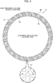
- dimples are arranged in at least either one of sliding faces which slide relative to each other of the rotating-side seal ring 3 and the stationary-side seal ring 5.
- the "dimple” means a dent having an opening part surrounded by the flat sliding faces S (land parts) and having a bottom recessed from the sliding faces S, and the shape thereof is not particularly limited.
- the shape of the opening part of the dent includes a circle, a triangle, an ellipse, an oval or a rectangle
- the sectional shape of the dent includes various shapes such as a cone, a truncated cone, a semicircle, a bowl or a square.
- a case where a plurality of dimples are arranged in the sliding face S of the stationary-side seal ring 5 will be described.
- the rotating-side seal ring 3 may or may not be provided with dimples.
- a plurality of dimples may be regularly arranged in the sliding face S and formed as an aligned dimple group, or may be irregularly arranged and formed as a random dimple group, or further may be arranged by a combination of an aligned dimple group and a random dimple group.
- a plurality of dimples 10 having a generally circular opening part are arranged.
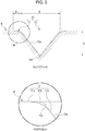
- the dimple 10 mainly consists of a concave part 15 whose sectional shape is a cone, and a peripheral edge part 11 which ranges to an outer peripheral part of a wall part 15a of the concave part 15 and grows wider in a trumpet shape.
- the concave part 15 has a bottom 15b having a depth G at the center thereof, and the wall part 15a which is inclined at an almost constant gradient toward the sliding face from the vicinity of the bottom 15b and whose opening is gradually increased.
- an opening diameter D of the concave part 15 in the sliding face S is defined as a diameter of an imaginary figure formed by intersection of an extension surface 15c, formed by extending the surface partitioning the wall part 15a, and the sliding face S.
- the peripheral edge part 11 consists of an outer peripheral edge part 11a which smoothly ranges to the sliding face S on the outside of the opening diameter D of the concave part 15, an inclined wall part 11b which is downwardly inclined toward the center part of the concave part 15 from the outer peripheral edge part 11a, is a convex curved surface toward the opposing sliding face (the interior of the dimple 10), and has a gradient smaller than the wall part 15a, and an inner peripheral edge part 11c in which the inclined wall part 11b and the wall part 15a range.
- the outer peripheral edge part 11a, the inclined wall part 11b, the inner peripheral edge part 11c and the wall part 15a may be a convex curved surface toward the interior of the dimple 10 as a whole.
- the bottom 15b of the concave part 15 has a pointed shape, the shape thereof is not limited thereto, and may be a hemisphere surface or a flat surface.
- the relationship of the depth G of the dimple 10, that is, the depth G of the concave part 15, a radial width E1 of the peripheral edge part 11, and the opening diameter D of the concave part 15 is set to about 0.25 ⁇ G/D ⁇ 1, 0.15 ⁇ E1/D ⁇ 0.5.
- the gradient of the peripheral edge part 11 is set to 1/100 or less.
- the opening diameter D, the dimple depth G, and the radial width E1 of the peripheral edge part 11 are formed to be about 36 ⁇ m, about 25 ⁇ m, and about 8 ⁇ m respectively.
- the opening diameter D of the concave part 15, the radial width E1 of the peripheral edge part 11, and the depth G of the concave part 15 are 10 ⁇ m to 60 ⁇ m, 5 ⁇ m to 20 ⁇ m, and 5 ⁇ m to 50 ⁇ m respectively.
- the peripheral edge part 11 of the dimple 10 is formed by the curved surface, and therefore the peripheral edge part 11 can easily form a gradient of about 1/1000 in the outer peripheral edge part 11a which smoothly ranges to the sliding face S.
- the mechanical seal 1 having the dimples 10 thus configured exhibits the following operation and effects.
- the fluid is suctioned from the sliding face S into the dimple 10 due to viscosity of the fluid, on the upstream side of the dimple 10, a negative pressure P1 is generated, and on the downstream side of the dimple 10, the fluid is increased in pressure due to a wedge effect and a positive pressure P2 is generated.
- cavitation is generated in a negative pressure portion on the upstream side of the dimple 10, the cavitation region has a pressure depending on the vapor pressure of the fluid, and therefore the peak of the negative pressure P1 is decreased.
- the effect of the positive pressure P2 is dominant in the dimple 10, and a load capability is generated and the sliding face S is lifted. Then, when the sliding face S is lifted, the gap between two sliding faces which relatively slide is increased, the fluid flows in the sliding face S, and a lubrication function is obtained.
- the peripheral edge part 11 of the dimple 10 is formed into a very small gradient of 1/100 or less, and therefore it is possible to constantly form a wedge part between the sliding face S of the rotating-side seal ring 3 and the sliding face S of the stationary-side seal ring 5.
- the fluid suctioned into the dimple 10 from the sliding face S efficiently generates a positive pressure in the wedge part of the peripheral edge part 11 on the downstream side, and also can increase a peak Pmax of the positive pressure P2.
- the radial width E1 is formed to be wide in the range of 0.15 ⁇ E1/D ⁇ 0.5, thereby capable of increasing the area of the region where the high positive pressure P2 is generated, and therefore it is possible to improve the force of lifting the sliding face S, that is, the load capability of the dimple 10.
- the sealed fluid is a high pressure fluid having a pressure of 1MPa or more, for example, about 5MPa, the sliding face S can certainly obtain a lubrication function.
- the depth G of the dimple 10 is formed deeply in the range of 0.25 ⁇ G/D ⁇ 1 with respect to the opening diameter D of the concave part 15, and therefore it is possible to increase the capacity of the concave part 15.
- the fluid suctioned into the dimple 10 is sufficiently stored in the concave part 15, it is possible to stably supply the fluid from the concave part 15 to the positive pressure region of the peripheral edge part 11, and therefore it is possible to exhibit a stable lubrication function without breaking the fluid film.
- the increased-pressure fluid which is suctioned into the dimples 10 arranged on the inner peripheral side of the sliding face and is discharged therefrom is further repeatedly suctioned into the plurality of dimples 10 arranged on the outer diameter side and is discharged therefrom, the fluid is carried to the outer peripheral part from the inner peripheral part of the sliding face S, and the sliding face S is improved in sealing function as a whole.
- the dimple 10 of the present invention is provided with the concave part 15 deeply formed, and, at the outer peripheral part of the concave part 15, the peripheral edge part 11 having a very small gradient and being wide, and therefore it is possible to efficiently enhance the load capability of the dimple 10.
- the plurality of dimples 10 enhanced in load capability are arranged in the sliding face S, thereby capable of enhancing lubrication performance and sealing performance in the sliding component as a whole.
- FIG. 5 Whereas the inclined wall part 11b of the peripheral edge part 11 in the first embodiment is formed by a curved surface, an inclined wall part 21b of a peripheral edge part 21 in the second embodiment is different in that it is formed by an inclined surface having a constant gradient.
- the same components as the components indicated in the above embodiment are denoted by the same reference signs, and redundant descriptions will be omitted.
- the dimple 10 mainly consists of the cone-shaped concave part 15, and the peripheral edge part 21 which ranges to the outer peripheral part of the wall part 15a of the concave part 15 and has a gradient smaller than the wall part 15a.
- the concave part 15 has the bottom 15b having the depth G at the center part thereof, and the wall part 15a which is inclined at an almost constant gradient toward the sliding face from the vicinity of the bottom 15b and whose opening is gradually increased.
- the opening diameter D of the cone-shaped concave part 15 is a diameter of an imaginary figure formed by intersection of the extension surface 15c, formed by extending the surface partitioning the wall part 15a, and the sliding face S.
- the peripheral edge part 21 consists of an outer peripheral edge part 21a which ranges to the sliding face S on the outside of the opening diameter D of the concave part 15, the inclined wall part 21b which is constantly downwardly inclined toward the center of the concave part 15 from the outer peripheral edge part 21a and has a gradient smaller than the wall part 15a, and an inner peripheral edge part 21c in which the inclined wall part 21b and the wall part 15a range.
- the relationship of the depth G of the dimple 10, a radial width E2 of the peripheral edge part 21, and the opening diameter D of the concave part 15 is set to about 0.25 ⁇ G/D ⁇ 1, 0.15 ⁇ E2/D ⁇ 0.5.
- the gradient of the peripheral edge part 21 is set to 1/100 or less.
- the opening diameter D, the dimple depth G, and the radial width E2 of the peripheral edge part 21 are formed to be about 36 ⁇ m, about 25 ⁇ m, and about 8 ⁇ m respectively.
- the opening diameter D of the concave part 15, the radial width E2 of the peripheral edge part 21, and the depth G of the concave part 15 are 10 ⁇ m to 60 ⁇ m, 5 ⁇ m to 20 ⁇ m, and 5 ⁇ m to 50 ⁇ m respectively.
- the peripheral edge part 21 of the dimple 10 is formed into a very small gradient of 1/100 or less, and therefore it is possible to constantly form a wedge part between the sliding face S of the rotating-side seal ring 3 and the sliding face S of the stationary-side seal ring 5.
- the fluid suctioned into the dimple 10 from the sliding face S efficiently generates a positive pressure in the wedge part of the peripheral edge part 21 on the downstream side, and also can increase the peak Pmax of the positive pressure P2.
- the radial width E2 is formed to be wide in the range of 0.15 ⁇ E2/D ⁇ 0.5, thereby capable of increasing the area of the region where the high positive pressure P2 is generated, and therefore it is possible to improve the load capability of the dimple 10.
- the depth G of the dimple 10 is formed deeply in the range of 0.25 ⁇ G/D ⁇ 1 with respect to the opening diameter D of the concave part 15, and therefore it is possible to increase the capacity of the concave part 15.
- the fluid suctioned into the dimple 10 is sufficiently stored in the concave part 15, it is possible to stably supply the fluid from the concave part 15 to the positive pressure region of the peripheral edge part 21, and therefore it is possible to exhibit stable lubrication performance without breaking the fluid film.
- the dimple 10 is provided with the concave part 15 deeply formed, and, at the outer peripheral part of the concave part 15, the peripheral edge part 21 having a very small gradient and being wide, and therefore it is possible to efficiently enhance the load capability of the dimple 10.
- the plurality of dimples 10 enhanced in load capability are arranged in the sliding face S, thereby capable of enhancing lubrication performance and sealing performance in the sliding component as a whole.
- the inclined wall part 21b of the peripheral edge part 21 is an inclined surface having a constant gradient, but is not limited thereto.
- an inner peripheral edge part 21d in which the inclined wall part 21b and the wall part 15a range may be a curved surface, thereby capable of reducing inflow resistance when the fluid flows in the wedge part. Thereby, high pressure is more efficiently generated in the peripheral edge part 21 of the dimple 10, and it is possible to increase the load capacity of the dimple 10.
- the sliding component according to a third embodiment will be described referring to FIG. 1 , FIG. 2 and FIG. 6 .
- the inclined wall part 11b of the peripheral edge part 11 in the first embodiment is formed by a curved surface and the inclined wall part 21b of a peripheral edge part 21 in the second embodiment is formed by an inclined surface having a constant gradient
- a bottom wall 31b of a peripheral edge part 31 in the third embodiment is different in that it has a bottom having a constant depth.
- the same components as the components indicated in the above embodiment are denoted by the same reference signs, and redundant descriptions will be omitted.
- the dimple 10 mainly consists of the cone-shaped concave part 15, and the peripheral edge part 31 which has a dent shallower than the concave part 15 on the outside of the wall part 15a of the concave part 15.
- the concave part 15 has the bottom 15b having the depth G at the center part thereof, and the wall part 15a which is inclined at an almost constant gradient toward the sliding face from the vicinity of the bottom 15b and whose opening is gradually increased.
- the opening diameter D of the con-shaped concave part 15 is defined as a diameter of an imaginary figure formed by intersection of the extension surface 15c, formed by extending the surface partitioning the wall part 15a, and the sliding face S.
- the peripheral edge part 31 consists of an outer peripheral edge part 31a which ranges to the sliding face S on the outside of the opening diameter D of the concave part 15, a peripheral wall 31e provided in a standing manner in the outer peripheral edge part 31a, a bottom wall 31b which ranges to the peripheral wall 31e and has a constant depth ⁇ , and an inner peripheral edge part 31c in which the bottom wall 31b and the wall part 15a range.
- the relationship of the depth G of the dimple 10 (the depth G of the concave part 15), a radial width E3 of the peripheral edge part 31, and the opening diameter D of the concave part 15 is set to about 0.25 ⁇ G/D ⁇ 1, 0.15 ⁇ E3/D ⁇ 0.5.
- the opening diameter D, the dimple depth G, and the radial width E3 of the peripheral edge part 31 are formed to be about 36 ⁇ m, about 25 ⁇ m, and about 8 ⁇ m respectively.
- the opening diameter D of the concave part 15, the radial width E3 of the peripheral edge part 31, the depth G of the concave part 15, and the depth ⁇ of the bottom wall 31b of the peripheral edge part 31 are 10 ⁇ m to 60 ⁇ m, 5 ⁇ m to 20 ⁇ m, 5 ⁇ m to 50 ⁇ m, and 1 ⁇ m to 5 ⁇ m respectively.
- the bottom wall 31b of the peripheral edge part 31 of the dimple 10 has the constant depth ⁇ , and therefore on the upstream side of the dimple 10, the bottom wall 31b functions as a reverse Rayleigh step, generates a negative pressure, and suctions the fluid with low loss into the dimple 10 from the sliding face S, and on the downstream side, the bottom wall 31b functions as a Rayleigh step and can generate a positive pressure.
- the radial width E3 is formed to be wide in the range of 0.15 ⁇ E3/D ⁇ 0.5, thereby capable of increasing the area of the region where the positive pressure is generated, and therefore it is possible to improve the load capability of the dimple 10.
- the depth G of the dimple 10 is formed deeply in the range of 0.25 ⁇ G/D ⁇ 1 with respect to the opening diameter D of the concave part 15, and therefore it is possible to increase the capacity of the concave part 15.
- the fluid suctioned into the dimple 10 is sufficiently stored in the concave part 15, it is possible to stably supply the fluid from the concave part 15 to the positive pressure region of the peripheral edge part 31, and therefore it is possible to exhibit stable lubrication performance without breaking the fluid film.
- the peripheral edge part 31 in the third embodiment has the bottom wall 31b having the constant depth ⁇ , and therefore it is possible to easily manufacture it, and efficiently enhance the load capability of the dimple 10.
- the plurality of dimples 10 enhanced in load capability are arranged in the sliding face S, thereby capable of enhancing lubrication performance and sealing performance in the sliding component as a whole.
- the bottom wall 31b of the peripheral edge part 31 has a constant depth, but is not limited thereto.
- an inner peripheral edge part 31d in which the bottom wall part 31b and the wall part 15a range may be a curved surface, thereby capable of reducing inflow resistance when the fluid flows in the Rayleigh step. Thereby, high pressure is more efficiently generated in the peripheral edge part 31 of the dimple 10, and it is possible to increase the load capacity of the dimple 10.
- the dimples 10 are provided in the whole surface of the sliding face S, but the present invention is not limited thereto.
- an island shaped dimple group is formed by surrounding the plurality of dimples 10 by the sliding face S, and the island shaped dimple group is arranged in a portion of the sliding face where the load is high, thereby sealing performance and lubrication performance may be improved.
- the island-shaped dimple group is communicated with the low pressure fluid side, and the suction amount from the low pressure fluid side is increased, thereby sealing performance may be further improved, or the island-shaped dimple group is communicated with the high pressure fluid side, and the fluid supply amount from the high pressure fluid side is increased, thereby lubrication performance may be further improved.
- the island-shaped dimple group is communicated with the low pressure fluid side and the high pressure fluid side, thereby sealing performance and lubrication performance may be further improved.
- the sliding component can also be used as a sliding component of a bearing which slides with a rotating shaft while sealing a lubricating oil on an axial one side of a cylindrical sliding face.
- the present invention is not limited thereto, and is also applicable to a case where the outer peripheral side is the low pressure fluid side (the leakage side) and the inner peripheral side is the high pressure fluid side (the sealed fluid side).
Landscapes
- Engineering & Computer Science (AREA)
- General Engineering & Computer Science (AREA)
- Mechanical Engineering (AREA)
- Chemical & Material Sciences (AREA)
- Oil, Petroleum & Natural Gas (AREA)
- Metallurgy (AREA)
- Physics & Mathematics (AREA)
- Fluid Mechanics (AREA)
- Mechanical Sealing (AREA)
- Sliding-Contact Bearings (AREA)
Applications Claiming Priority (2)
| Application Number | Priority Date | Filing Date | Title |
|---|---|---|---|
| JP2017133953 | 2017-07-07 | ||
| PCT/JP2018/025425 WO2019009345A1 (fr) | 2017-07-07 | 2018-07-04 | Élément coulissant |
Publications (3)
| Publication Number | Publication Date |
|---|---|
| EP3650722A1 true EP3650722A1 (fr) | 2020-05-13 |
| EP3650722A4 EP3650722A4 (fr) | 2020-12-30 |
| EP3650722B1 EP3650722B1 (fr) | 2022-01-19 |
Family
ID=64950111
Family Applications (1)
| Application Number | Title | Priority Date | Filing Date |
|---|---|---|---|
| EP18828562.1A Active EP3650722B1 (fr) | 2017-07-07 | 2018-07-04 | Élément glissant |
Country Status (6)
| Country | Link |
|---|---|
| US (1) | US11248706B2 (fr) |
| EP (1) | EP3650722B1 (fr) |
| JP (1) | JP7086489B2 (fr) |
| KR (1) | KR102302877B1 (fr) |
| CN (1) | CN110770456B (fr) |
| WO (1) | WO2019009345A1 (fr) |
Cited By (17)
| Publication number | Priority date | Publication date | Assignee | Title |
|---|---|---|---|---|
| EP3748205A4 (fr) * | 2018-02-01 | 2021-11-10 | Eagle Industry Co., Ltd. | Pièces coulissantes |
| US11391376B2 (en) | 2016-08-15 | 2022-07-19 | Eagle Industry Co., Ltd. | Sliding component |
| CN115768989A (zh) * | 2020-07-06 | 2023-03-07 | 伊格尔工业股份有限公司 | 滑动部件 |
| US11603934B2 (en) | 2018-01-12 | 2023-03-14 | Eagle Industry Co., Ltd. | Sliding component |
| US11913454B2 (en) | 2020-07-06 | 2024-02-27 | Eagle Industry Co., Ltd. | Sliding component |
| US11933303B2 (en) | 2020-07-06 | 2024-03-19 | Eagle Industry Co., Ltd. | Sliding component |
| US12135030B2 (en) | 2020-07-06 | 2024-11-05 | Eagle Industry Co., Ltd. | Sliding component |
| US12152676B2 (en) | 2020-07-06 | 2024-11-26 | Eagle Industry Co., Ltd. | Sliding component |
| US12196320B2 (en) | 2020-03-31 | 2025-01-14 | Eagle Industry Co., Ltd. | Sliding component |
| US12209668B2 (en) | 2019-02-04 | 2025-01-28 | Eagle Industry Co., Ltd. | Sliding component |
| US12259043B2 (en) | 2019-02-04 | 2025-03-25 | Eagle Industry Co., Ltd. | Sliding component |
| US12404935B2 (en) | 2020-07-06 | 2025-09-02 | Eagle Industry Co., Ltd. | Sliding component |
| US12449040B2 (en) | 2020-05-11 | 2025-10-21 | Eagle Industry Co., Ltd. | Sliding component |
| US12467538B2 (en) | 2019-03-22 | 2025-11-11 | Eagle Industry Co., Ltd. | Sliding component |
| US12498044B2 (en) | 2019-02-04 | 2025-12-16 | Eagle Industry Co., Ltd. | Sliding component |
| US12560239B2 (en) | 2021-08-25 | 2026-02-24 | Eagle Industry Co., Ltd. | Sliding components |
| USRE50849E1 (en) | 2016-11-16 | 2026-03-31 | Eagle Industry Co., Ltd. | Sliding component |
Families Citing this family (6)
| Publication number | Priority date | Publication date | Assignee | Title |
|---|---|---|---|---|
| JP7275028B2 (ja) * | 2017-05-19 | 2023-05-17 | イーグル工業株式会社 | 摺動部品 |
| EP3693638A4 (fr) | 2017-10-03 | 2021-06-23 | Eagle Industry Co., Ltd. | Élément coulissant |
| EP4253779B1 (fr) | 2019-02-04 | 2024-12-18 | Eagle Industry Co., Ltd. | Composant glissant et procédé de fabrication de composant glissant |
| EP3922874A4 (fr) | 2019-02-04 | 2022-11-09 | Eagle Industry Co., Ltd. | Élément coulissant |
| US11692628B2 (en) * | 2020-10-26 | 2023-07-04 | Changshu Institute Of Technology | Sealing device for gas-liquid two-phase fluid medium under variable working conditions |
| CN119301388A (zh) * | 2022-06-07 | 2025-01-10 | 伊格尔工业股份有限公司 | 滑动部件 |
Family Cites Families (15)
| Publication number | Priority date | Publication date | Assignee | Title |
|---|---|---|---|---|
| JPS5235452A (en) | 1975-09-13 | 1977-03-18 | Kubota Ltd | Ascent-descent type sand hoist |
| DE9310059U1 (de) * | 1993-07-07 | 1994-11-10 | MACOR Marine Systems International GmbH, 28329 Bremen | Gleitlager insbesondere für Lukendeckel an Bord von Schiffen |
| US5834094A (en) * | 1996-09-30 | 1998-11-10 | Surface Technologies Ltd. | Bearing having micropores and design method thereof |
| US6902168B2 (en) * | 2002-03-19 | 2005-06-07 | Eagle Industry Co., Ltd. | Sliding element |
| JP4495402B2 (ja) | 2002-03-19 | 2010-07-07 | イーグル工業株式会社 | 摺動部品 |
| JP2007092983A (ja) | 2005-09-01 | 2007-04-12 | Ntn Corp | ころ軸受 |
| JP2010133496A (ja) * | 2008-12-04 | 2010-06-17 | Eagle Ind Co Ltd | 摺動部品 |
| JP5518527B2 (ja) | 2010-03-04 | 2014-06-11 | イーグル工業株式会社 | 摺動部品 |
| CN103097782B (zh) * | 2010-10-06 | 2016-01-20 | 伊格尔工业股份有限公司 | 滑动部件 |
| WO2013176010A1 (fr) * | 2012-05-21 | 2013-11-28 | イーグル工業株式会社 | Composant coulissant |
| CN104919229B (zh) * | 2013-04-24 | 2017-05-31 | 伊格尔工业股份有限公司 | 滑动部件 |
| DE102013109025A1 (de) * | 2013-08-21 | 2015-02-26 | Mag Ias Gmbh | Gleitfläche |
| JP6763850B2 (ja) * | 2015-03-11 | 2020-09-30 | イーグル工業株式会社 | しゅう動部品及びしゅう動部品の製造方法 |
| JP6776232B2 (ja) * | 2015-06-15 | 2020-10-28 | イーグル工業株式会社 | 摺動部品 |
| CN105485168B (zh) * | 2016-01-07 | 2017-12-29 | 燕山大学 | 一种径向支承垫织构表面摩擦副 |
-
2018
- 2018-07-04 US US16/622,826 patent/US11248706B2/en active Active
- 2018-07-04 CN CN201880040725.XA patent/CN110770456B/zh active Active
- 2018-07-04 JP JP2019527756A patent/JP7086489B2/ja active Active
- 2018-07-04 WO PCT/JP2018/025425 patent/WO2019009345A1/fr not_active Ceased
- 2018-07-04 KR KR1020197037621A patent/KR102302877B1/ko active Active
- 2018-07-04 EP EP18828562.1A patent/EP3650722B1/fr active Active
Cited By (21)
| Publication number | Priority date | Publication date | Assignee | Title |
|---|---|---|---|---|
| US11391376B2 (en) | 2016-08-15 | 2022-07-19 | Eagle Industry Co., Ltd. | Sliding component |
| USRE50849E1 (en) | 2016-11-16 | 2026-03-31 | Eagle Industry Co., Ltd. | Sliding component |
| US11603934B2 (en) | 2018-01-12 | 2023-03-14 | Eagle Industry Co., Ltd. | Sliding component |
| US11320052B2 (en) | 2018-02-01 | 2022-05-03 | Eagle Industry Co., Ltd. | Sliding components |
| US11619308B2 (en) | 2018-02-01 | 2023-04-04 | Eagle Industry Co., Ltd. | Sliding components |
| EP3748205A4 (fr) * | 2018-02-01 | 2021-11-10 | Eagle Industry Co., Ltd. | Pièces coulissantes |
| US12498044B2 (en) | 2019-02-04 | 2025-12-16 | Eagle Industry Co., Ltd. | Sliding component |
| US12259043B2 (en) | 2019-02-04 | 2025-03-25 | Eagle Industry Co., Ltd. | Sliding component |
| US12209668B2 (en) | 2019-02-04 | 2025-01-28 | Eagle Industry Co., Ltd. | Sliding component |
| US12467538B2 (en) | 2019-03-22 | 2025-11-11 | Eagle Industry Co., Ltd. | Sliding component |
| US12196320B2 (en) | 2020-03-31 | 2025-01-14 | Eagle Industry Co., Ltd. | Sliding component |
| US12449040B2 (en) | 2020-05-11 | 2025-10-21 | Eagle Industry Co., Ltd. | Sliding component |
| US12135030B2 (en) | 2020-07-06 | 2024-11-05 | Eagle Industry Co., Ltd. | Sliding component |
| US12152676B2 (en) | 2020-07-06 | 2024-11-26 | Eagle Industry Co., Ltd. | Sliding component |
| US12104598B2 (en) | 2020-07-06 | 2024-10-01 | Eagle Industry Co., Ltd. | Eccentric sliding assembly with a plurality of dynamic pressure generation mechanisms |
| US12404935B2 (en) | 2020-07-06 | 2025-09-02 | Eagle Industry Co., Ltd. | Sliding component |
| EP4177486A4 (fr) * | 2020-07-06 | 2024-07-31 | Eagle Industry Co., Ltd. | Élément coulissant |
| US11933303B2 (en) | 2020-07-06 | 2024-03-19 | Eagle Industry Co., Ltd. | Sliding component |
| US11913454B2 (en) | 2020-07-06 | 2024-02-27 | Eagle Industry Co., Ltd. | Sliding component |
| CN115768989A (zh) * | 2020-07-06 | 2023-03-07 | 伊格尔工业股份有限公司 | 滑动部件 |
| US12560239B2 (en) | 2021-08-25 | 2026-02-24 | Eagle Industry Co., Ltd. | Sliding components |
Also Published As
| Publication number | Publication date |
|---|---|
| JP7086489B2 (ja) | 2022-06-20 |
| KR102302877B1 (ko) | 2021-09-17 |
| EP3650722A4 (fr) | 2020-12-30 |
| WO2019009345A1 (fr) | 2019-01-10 |
| US11248706B2 (en) | 2022-02-15 |
| CN110770456B (zh) | 2021-11-09 |
| JPWO2019009345A1 (ja) | 2020-05-07 |
| US20210048106A1 (en) | 2021-02-18 |
| EP3650722B1 (fr) | 2022-01-19 |
| KR20200008160A (ko) | 2020-01-23 |
| CN110770456A (zh) | 2020-02-07 |
Similar Documents
| Publication | Publication Date | Title |
|---|---|---|
| EP3650722B1 (fr) | Élément glissant | |
| US11708911B2 (en) | Sliding component | |
| KR102682943B1 (ko) | 슬라이딩 부품 | |
| US10132411B2 (en) | Sliding component | |
| JP6080845B2 (ja) | 摺動部品 | |
| AU2015281104B2 (en) | Sliding component | |
| EP2881633B1 (fr) | Composant de coulissement | |
| JP6776232B2 (ja) | 摺動部品 | |
| JP6076971B2 (ja) | 摺動部品 | |
| CN110785587B (zh) | 滑动部件 | |
| CN104185756B (zh) | 滑动部件 | |
| EP3627011A1 (fr) | Composant coulissant | |
| JP7171553B2 (ja) | 摺動部品 | |
| WO2022230460A1 (fr) | Élément coulissant | |
| US10774876B1 (en) | Hydrodynamic thrust washers with pumping features for sparse lubrication applications | |
| US12196320B2 (en) | Sliding component | |
| WO2025239228A1 (fr) | Composant coulissant |
Legal Events
| Date | Code | Title | Description |
|---|---|---|---|
| STAA | Information on the status of an ep patent application or granted ep patent |
Free format text: STATUS: THE INTERNATIONAL PUBLICATION HAS BEEN MADE |
|
| PUAI | Public reference made under article 153(3) epc to a published international application that has entered the european phase |
Free format text: ORIGINAL CODE: 0009012 |
|
| STAA | Information on the status of an ep patent application or granted ep patent |
Free format text: STATUS: REQUEST FOR EXAMINATION WAS MADE |
|
| 17P | Request for examination filed |
Effective date: 20191223 |
|
| AK | Designated contracting states |
Kind code of ref document: A1 Designated state(s): AL AT BE BG CH CY CZ DE DK EE ES FI FR GB GR HR HU IE IS IT LI LT LU LV MC MK MT NL NO PL PT RO RS SE SI SK SM TR |
|
| AX | Request for extension of the european patent |
Extension state: BA ME |
|
| DAV | Request for validation of the european patent (deleted) | ||
| DAX | Request for extension of the european patent (deleted) | ||
| A4 | Supplementary search report drawn up and despatched |
Effective date: 20201202 |
|
| RIC1 | Information provided on ipc code assigned before grant |
Ipc: F16C 33/24 20060101ALI20201126BHEP Ipc: F16C 33/10 20060101ALI20201126BHEP Ipc: F16C 33/12 20060101AFI20201126BHEP Ipc: F16C 33/14 20060101ALI20201126BHEP Ipc: F16C 17/04 20060101ALI20201126BHEP Ipc: F16J 15/34 20060101ALI20201126BHEP |
|
| GRAP | Despatch of communication of intention to grant a patent |
Free format text: ORIGINAL CODE: EPIDOSNIGR1 |
|
| STAA | Information on the status of an ep patent application or granted ep patent |
Free format text: STATUS: GRANT OF PATENT IS INTENDED |
|
| INTG | Intention to grant announced |
Effective date: 20211027 |
|
| GRAS | Grant fee paid |
Free format text: ORIGINAL CODE: EPIDOSNIGR3 |
|
| GRAA | (expected) grant |
Free format text: ORIGINAL CODE: 0009210 |
|
| STAA | Information on the status of an ep patent application or granted ep patent |
Free format text: STATUS: THE PATENT HAS BEEN GRANTED |
|
| AK | Designated contracting states |
Kind code of ref document: B1 Designated state(s): AL AT BE BG CH CY CZ DE DK EE ES FI FR GB GR HR HU IE IS IT LI LT LU LV MC MK MT NL NO PL PT RO RS SE SI SK SM TR |
|
| REG | Reference to a national code |
Ref country code: GB Ref legal event code: FG4D |
|
| REG | Reference to a national code |
Ref country code: CH Ref legal event code: EP |
|
| REG | Reference to a national code |
Ref country code: DE Ref legal event code: R096 Ref document number: 602018029871 Country of ref document: DE |
|
| REG | Reference to a national code |
Ref country code: AT Ref legal event code: REF Ref document number: 1463953 Country of ref document: AT Kind code of ref document: T Effective date: 20220215 |
|
| REG | Reference to a national code |
Ref country code: IE Ref legal event code: FG4D |
|
| REG | Reference to a national code |
Ref country code: LT Ref legal event code: MG9D |
|
| REG | Reference to a national code |
Ref country code: NL Ref legal event code: MP Effective date: 20220119 |
|
| REG | Reference to a national code |
Ref country code: AT Ref legal event code: MK05 Ref document number: 1463953 Country of ref document: AT Kind code of ref document: T Effective date: 20220119 |
|
| PG25 | Lapsed in a contracting state [announced via postgrant information from national office to epo] |
Ref country code: NL Free format text: LAPSE BECAUSE OF FAILURE TO SUBMIT A TRANSLATION OF THE DESCRIPTION OR TO PAY THE FEE WITHIN THE PRESCRIBED TIME-LIMIT Effective date: 20220119 |
|
| PG25 | Lapsed in a contracting state [announced via postgrant information from national office to epo] |
Ref country code: SE Free format text: LAPSE BECAUSE OF FAILURE TO SUBMIT A TRANSLATION OF THE DESCRIPTION OR TO PAY THE FEE WITHIN THE PRESCRIBED TIME-LIMIT Effective date: 20220119 Ref country code: RS Free format text: LAPSE BECAUSE OF FAILURE TO SUBMIT A TRANSLATION OF THE DESCRIPTION OR TO PAY THE FEE WITHIN THE PRESCRIBED TIME-LIMIT Effective date: 20220119 Ref country code: PT Free format text: LAPSE BECAUSE OF FAILURE TO SUBMIT A TRANSLATION OF THE DESCRIPTION OR TO PAY THE FEE WITHIN THE PRESCRIBED TIME-LIMIT Effective date: 20220519 Ref country code: NO Free format text: LAPSE BECAUSE OF FAILURE TO SUBMIT A TRANSLATION OF THE DESCRIPTION OR TO PAY THE FEE WITHIN THE PRESCRIBED TIME-LIMIT Effective date: 20220419 Ref country code: LT Free format text: LAPSE BECAUSE OF FAILURE TO SUBMIT A TRANSLATION OF THE DESCRIPTION OR TO PAY THE FEE WITHIN THE PRESCRIBED TIME-LIMIT Effective date: 20220119 Ref country code: HR Free format text: LAPSE BECAUSE OF FAILURE TO SUBMIT A TRANSLATION OF THE DESCRIPTION OR TO PAY THE FEE WITHIN THE PRESCRIBED TIME-LIMIT Effective date: 20220119 Ref country code: ES Free format text: LAPSE BECAUSE OF FAILURE TO SUBMIT A TRANSLATION OF THE DESCRIPTION OR TO PAY THE FEE WITHIN THE PRESCRIBED TIME-LIMIT Effective date: 20220119 Ref country code: BG Free format text: LAPSE BECAUSE OF FAILURE TO SUBMIT A TRANSLATION OF THE DESCRIPTION OR TO PAY THE FEE WITHIN THE PRESCRIBED TIME-LIMIT Effective date: 20220419 |
|
| PG25 | Lapsed in a contracting state [announced via postgrant information from national office to epo] |
Ref country code: PL Free format text: LAPSE BECAUSE OF FAILURE TO SUBMIT A TRANSLATION OF THE DESCRIPTION OR TO PAY THE FEE WITHIN THE PRESCRIBED TIME-LIMIT Effective date: 20220119 Ref country code: LV Free format text: LAPSE BECAUSE OF FAILURE TO SUBMIT A TRANSLATION OF THE DESCRIPTION OR TO PAY THE FEE WITHIN THE PRESCRIBED TIME-LIMIT Effective date: 20220119 Ref country code: GR Free format text: LAPSE BECAUSE OF FAILURE TO SUBMIT A TRANSLATION OF THE DESCRIPTION OR TO PAY THE FEE WITHIN THE PRESCRIBED TIME-LIMIT Effective date: 20220420 Ref country code: FI Free format text: LAPSE BECAUSE OF FAILURE TO SUBMIT A TRANSLATION OF THE DESCRIPTION OR TO PAY THE FEE WITHIN THE PRESCRIBED TIME-LIMIT Effective date: 20220119 Ref country code: AT Free format text: LAPSE BECAUSE OF FAILURE TO SUBMIT A TRANSLATION OF THE DESCRIPTION OR TO PAY THE FEE WITHIN THE PRESCRIBED TIME-LIMIT Effective date: 20220119 |
|
| PG25 | Lapsed in a contracting state [announced via postgrant information from national office to epo] |
Ref country code: IS Free format text: LAPSE BECAUSE OF FAILURE TO SUBMIT A TRANSLATION OF THE DESCRIPTION OR TO PAY THE FEE WITHIN THE PRESCRIBED TIME-LIMIT Effective date: 20220519 |
|
| REG | Reference to a national code |
Ref country code: DE Ref legal event code: R097 Ref document number: 602018029871 Country of ref document: DE |
|
| PG25 | Lapsed in a contracting state [announced via postgrant information from national office to epo] |
Ref country code: SM Free format text: LAPSE BECAUSE OF FAILURE TO SUBMIT A TRANSLATION OF THE DESCRIPTION OR TO PAY THE FEE WITHIN THE PRESCRIBED TIME-LIMIT Effective date: 20220119 Ref country code: SK Free format text: LAPSE BECAUSE OF FAILURE TO SUBMIT A TRANSLATION OF THE DESCRIPTION OR TO PAY THE FEE WITHIN THE PRESCRIBED TIME-LIMIT Effective date: 20220119 Ref country code: RO Free format text: LAPSE BECAUSE OF FAILURE TO SUBMIT A TRANSLATION OF THE DESCRIPTION OR TO PAY THE FEE WITHIN THE PRESCRIBED TIME-LIMIT Effective date: 20220119 Ref country code: EE Free format text: LAPSE BECAUSE OF FAILURE TO SUBMIT A TRANSLATION OF THE DESCRIPTION OR TO PAY THE FEE WITHIN THE PRESCRIBED TIME-LIMIT Effective date: 20220119 Ref country code: DK Free format text: LAPSE BECAUSE OF FAILURE TO SUBMIT A TRANSLATION OF THE DESCRIPTION OR TO PAY THE FEE WITHIN THE PRESCRIBED TIME-LIMIT Effective date: 20220119 Ref country code: CZ Free format text: LAPSE BECAUSE OF FAILURE TO SUBMIT A TRANSLATION OF THE DESCRIPTION OR TO PAY THE FEE WITHIN THE PRESCRIBED TIME-LIMIT Effective date: 20220119 |
|
| PLBE | No opposition filed within time limit |
Free format text: ORIGINAL CODE: 0009261 |
|
| STAA | Information on the status of an ep patent application or granted ep patent |
Free format text: STATUS: NO OPPOSITION FILED WITHIN TIME LIMIT |
|
| PG25 | Lapsed in a contracting state [announced via postgrant information from national office to epo] |
Ref country code: AL Free format text: LAPSE BECAUSE OF FAILURE TO SUBMIT A TRANSLATION OF THE DESCRIPTION OR TO PAY THE FEE WITHIN THE PRESCRIBED TIME-LIMIT Effective date: 20220119 |
|
| 26N | No opposition filed |
Effective date: 20221020 |
|
| PG25 | Lapsed in a contracting state [announced via postgrant information from national office to epo] |
Ref country code: SI Free format text: LAPSE BECAUSE OF FAILURE TO SUBMIT A TRANSLATION OF THE DESCRIPTION OR TO PAY THE FEE WITHIN THE PRESCRIBED TIME-LIMIT Effective date: 20220119 Ref country code: MC Free format text: LAPSE BECAUSE OF FAILURE TO SUBMIT A TRANSLATION OF THE DESCRIPTION OR TO PAY THE FEE WITHIN THE PRESCRIBED TIME-LIMIT Effective date: 20220119 |
|
| REG | Reference to a national code |
Ref country code: CH Ref legal event code: PL |
|
| REG | Reference to a national code |
Ref country code: BE Ref legal event code: MM Effective date: 20220731 |
|
| PG25 | Lapsed in a contracting state [announced via postgrant information from national office to epo] |
Ref country code: LU Free format text: LAPSE BECAUSE OF NON-PAYMENT OF DUE FEES Effective date: 20220704 Ref country code: LI Free format text: LAPSE BECAUSE OF NON-PAYMENT OF DUE FEES Effective date: 20220731 Ref country code: CH Free format text: LAPSE BECAUSE OF NON-PAYMENT OF DUE FEES Effective date: 20220731 |
|
| PG25 | Lapsed in a contracting state [announced via postgrant information from national office to epo] |
Ref country code: BE Free format text: LAPSE BECAUSE OF NON-PAYMENT OF DUE FEES Effective date: 20220731 |
|
| PG25 | Lapsed in a contracting state [announced via postgrant information from national office to epo] |
Ref country code: IE Free format text: LAPSE BECAUSE OF NON-PAYMENT OF DUE FEES Effective date: 20220704 |
|
| PG25 | Lapsed in a contracting state [announced via postgrant information from national office to epo] |
Ref country code: MK Free format text: LAPSE BECAUSE OF FAILURE TO SUBMIT A TRANSLATION OF THE DESCRIPTION OR TO PAY THE FEE WITHIN THE PRESCRIBED TIME-LIMIT Effective date: 20220119 Ref country code: CY Free format text: LAPSE BECAUSE OF FAILURE TO SUBMIT A TRANSLATION OF THE DESCRIPTION OR TO PAY THE FEE WITHIN THE PRESCRIBED TIME-LIMIT Effective date: 20220119 |
|
| PG25 | Lapsed in a contracting state [announced via postgrant information from national office to epo] |
Ref country code: HU Free format text: LAPSE BECAUSE OF FAILURE TO SUBMIT A TRANSLATION OF THE DESCRIPTION OR TO PAY THE FEE WITHIN THE PRESCRIBED TIME-LIMIT; INVALID AB INITIO Effective date: 20180704 |
|
| PG25 | Lapsed in a contracting state [announced via postgrant information from national office to epo] |
Ref country code: MT Free format text: LAPSE BECAUSE OF FAILURE TO SUBMIT A TRANSLATION OF THE DESCRIPTION OR TO PAY THE FEE WITHIN THE PRESCRIBED TIME-LIMIT Effective date: 20220119 |
|
| PGFP | Annual fee paid to national office [announced via postgrant information from national office to epo] |
Ref country code: GB Payment date: 20250529 Year of fee payment: 8 |
|
| PGFP | Annual fee paid to national office [announced via postgrant information from national office to epo] |
Ref country code: FR Payment date: 20250610 Year of fee payment: 8 |
|
| PGFP | Annual fee paid to national office [announced via postgrant information from national office to epo] |
Ref country code: DE Payment date: 20250528 Year of fee payment: 8 |
|
| PGFP | Annual fee paid to national office [announced via postgrant information from national office to epo] |
Ref country code: IT Payment date: 20250623 Year of fee payment: 8 |
|
| PG25 | Lapsed in a contracting state [announced via postgrant information from national office to epo] |
Ref country code: TR Free format text: LAPSE BECAUSE OF FAILURE TO SUBMIT A TRANSLATION OF THE DESCRIPTION OR TO PAY THE FEE WITHIN THE PRESCRIBED TIME-LIMIT Effective date: 20220119 |