EP3650745B1 - Beleuchtungsvorrichtung für fahrzeuge mit lichtleitern - Google Patents
Beleuchtungsvorrichtung für fahrzeuge mit lichtleitern Download PDFInfo
- Publication number
- EP3650745B1 EP3650745B1 EP19208726.0A EP19208726A EP3650745B1 EP 3650745 B1 EP3650745 B1 EP 3650745B1 EP 19208726 A EP19208726 A EP 19208726A EP 3650745 B1 EP3650745 B1 EP 3650745B1
- Authority
- EP
- European Patent Office
- Prior art keywords
- housing
- lighting device
- seat
- interface element
- light guides
- Prior art date
- Legal status (The legal status is an assumption and is not a legal conclusion. Google has not performed a legal analysis and makes no representation as to the accuracy of the status listed.)
- Active
Links
Images



Classifications
-
- F—MECHANICAL ENGINEERING; LIGHTING; HEATING; WEAPONS; BLASTING
- F21—LIGHTING
- F21S—NON-PORTABLE LIGHTING DEVICES; SYSTEMS THEREOF; VEHICLE LIGHTING DEVICES SPECIALLY ADAPTED FOR VEHICLE EXTERIORS
- F21S43/00—Signalling devices specially adapted for vehicle exteriors, e.g. brake lamps, direction indicator lights or reversing lights
- F21S43/20—Signalling devices specially adapted for vehicle exteriors, e.g. brake lamps, direction indicator lights or reversing lights characterised by refractors, transparent cover plates, light guides or filters
- F21S43/235—Light guides
- F21S43/236—Light guides characterised by the shape of the light guide
- F21S43/237—Light guides characterised by the shape of the light guide rod-shaped
-
- F—MECHANICAL ENGINEERING; LIGHTING; HEATING; WEAPONS; BLASTING
- F21—LIGHTING
- F21S—NON-PORTABLE LIGHTING DEVICES; SYSTEMS THEREOF; VEHICLE LIGHTING DEVICES SPECIALLY ADAPTED FOR VEHICLE EXTERIORS
- F21S43/00—Signalling devices specially adapted for vehicle exteriors, e.g. brake lamps, direction indicator lights or reversing lights
- F21S43/10—Signalling devices specially adapted for vehicle exteriors, e.g. brake lamps, direction indicator lights or reversing lights characterised by the light source
- F21S43/13—Signalling devices specially adapted for vehicle exteriors, e.g. brake lamps, direction indicator lights or reversing lights characterised by the light source characterised by the type of light source
- F21S43/14—Light emitting diodes [LED]
-
- F—MECHANICAL ENGINEERING; LIGHTING; HEATING; WEAPONS; BLASTING
- F21—LIGHTING
- F21S—NON-PORTABLE LIGHTING DEVICES; SYSTEMS THEREOF; VEHICLE LIGHTING DEVICES SPECIALLY ADAPTED FOR VEHICLE EXTERIORS
- F21S43/00—Signalling devices specially adapted for vehicle exteriors, e.g. brake lamps, direction indicator lights or reversing lights
- F21S43/10—Signalling devices specially adapted for vehicle exteriors, e.g. brake lamps, direction indicator lights or reversing lights characterised by the light source
- F21S43/19—Attachment of light sources or lamp holders
- F21S43/195—Details of lamp holders, terminals or connectors
-
- F—MECHANICAL ENGINEERING; LIGHTING; HEATING; WEAPONS; BLASTING
- F21—LIGHTING
- F21S—NON-PORTABLE LIGHTING DEVICES; SYSTEMS THEREOF; VEHICLE LIGHTING DEVICES SPECIALLY ADAPTED FOR VEHICLE EXTERIORS
- F21S43/00—Signalling devices specially adapted for vehicle exteriors, e.g. brake lamps, direction indicator lights or reversing lights
- F21S43/20—Signalling devices specially adapted for vehicle exteriors, e.g. brake lamps, direction indicator lights or reversing lights characterised by refractors, transparent cover plates, light guides or filters
- F21S43/27—Attachment thereof
Definitions
- the invention relates to a lighting device for vehicles, in particular a headlight for a vehicle, such as a motor vehicle, wherein one or more light guides are used, which are preferably lit by LEDs and are designed to carry out signalling functions (for example: position, direction, DRL) or aesthetic functions.
- a lighting device for vehicles in particular a headlight for a vehicle, such as a motor vehicle, wherein one or more light guides are used, which are preferably lit by LEDs and are designed to carry out signalling functions (for example: position, direction, DRL) or aesthetic functions.
- a vehicle lighting device comprises a cup-shaped body or housing, which is generally manufactured by moulding of a synthetic plastic material, at least one lighting element, which is housed in the cup-shaped body, and a transparent element, which closes a front opening of the cup-shaped body and, in use, faces the driving direction of the vehicle.
- light guides which are lit by means of one or more LEDs (or by means of other different light sources), are used as lighting elements, in particular in order to carry out signalling functions, as position lamps, direction lights, DRL, etcetera.
- the transparent element or lens closing the front opening of the headlight body is optically neutral and different light guides are placed inside the headlight body so as to be visible through the transparent element.
- the LEDs (or other different lighting sources) used to light the light guides are carried at the back by the cup-shaped housing or body, in the area of a rear through seat thereof, which is not necessarily aligned with the front opening, or in the area of a lateral through seat thereof, since the light guides usually consist of elongated rod-shaped elements, which are flexible or anyway curved and receive the light at a first end of theirs in order to be then party or entirely lit over their length or in order to be lit only in the area of a second end of theirs, which is opposite the first one.
- Said rear or lateral through seat of the cup-shaped body is closed by a plate-shaped support element carrying the LED/s and externally fixed, in a removable manner, to the cup-shaped body or housing.
- the plate-shaped support element is usually provided with the necessary electrical connections and with heat dissipators used to dispose of the heat produced, in use, by the LEDs.
- the light guides are assembled on the headlight body or housing before mounting the plate-shaped support with the LEDs already assembled on it, there is the problem of ensuring a correct placing of the first ends of the light guides relative to the respective lighting LEDs, which are all carried by the same plate-shaped support.
- the light guides are assembled, on the side of their first end, on an interface element, which is preferably provided with elastically deformable seats, which are configured to receive, in a through manner, the first ends of the light guide or of the bundle of light guides to be lit.
- the interface element is configured to be housed in the aforesaid rear or lateral through seat of the cup-shaped housing or body with a radial clearance.
- an adapter element is fixed on the interface element in an integral manner, on the opposite side relative to the light guides, and is coupled, substantially without clearances, within the through seat, said adapter element being provided with through seats, which are designed to be coupled, substantially without clearances, to the first ends of the light guides, which, therefore, are forced to assume a correct position relative to the housing.
- US 2016/281954 A1 discloses such a lighting device for a vehicle.
- the object of the invention is to provide a lighting device for vehicles, in particular a headlight or lamp for motor vehicles, which is not affected by the drawbacks of the prior art and, in particular, allows, in a simple, economic and compact fashion, for the recovery of assembling clearances of the light guides along all the three axes defining the position thereof relative to the lighting LED/s (or other light source).
- a lighting device for vehicles in particular a headlight or lamp for motor vehicles, according to the appended claims.
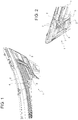
- reference number 1 indicates, as a whole, a front headlight for motor vehicles, which is configured to be fixed in a known manner, which is not shown herein for the sake of simplicity, to the body of a vehicle (which is also known and not shown).
- the lighting device 1 comprises a housing 2, at least one lighting element 3, which is at least partly housed in the housing 2 so as to be at least partly visible from the outside through a front opening 4 of the housing 2, and at least one light source 5, which is arranged on a support element 6, well shown in figure 3 , and is configured to at least partly light the lighting element 3.
- the lighting element consists of at least one known light guide 3, which has an elongated shape and includes a first end 7 facing away from the front opening 4.
- the lighting element consists of a bundle of light guides 3 beside one another, whose respective first ends 7 are each operatively associated with a respective LED or group of LEDs 5 carried by the support element 6.
- the support element 6 is coupled to the housing 2 in a removable manner so as to close a through seat 8 of the housing 2 arranged at the back or on the side thereof.
- each light guide 3 is housed so as to go through an interface element 9 and an adapter element 10, which, in turn, is coupled to the interface element 9 in an integral manner and is arranged between the latter and the support element 6 for the LEDs 5, facing them.
- the adapter element 10 and the interface element 9 are both housed, in the way described below, within the through seat 8 of the housing 2.
- the adapter element 10 is constrained to the interface element 9 by means of a screw 11 and a threaded nut 12.
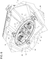
- the screw 11 comprises ( figure 5 ) an activation head 13 and a shank 14 having a first threaded stretch 15 and a second threaded stretch 16 arranged between the activation head 13 and the threaded stretch 15.
- the first threaded stretch 15 is screwed into a reception seat 18 of the interface element 9 so that the screw 11 and the interface element 9 are movable relative to one another along an axis of symmetry A of the screw 11.
- the first threaded stretch 15 is self-tapping and the reception seat of the interface element 9 designed to receive it, into which the first threaded stretch 15 is screwed with the possibility of making a predetermined axial movement, is defined by a smooth lateral wall of a recess defined by a cup-shaped portion 19 of a bottom wall 20 of the interface element 9.
- the cup-shaped portion 19 of the bottom wall 20 projects from the bottom wall 20, on the opposite side relative to the first ends 7 of the light guides 3 and, hence, towards the front opening 4.
- the threaded nut 12 is screwed onto the second threaded stretch 16 so as to axially strike against a bottom wall 21 of the adapter element 10.
- the adapter element 10 furthermore, has a peripherally outer edge 22, which is coupled to an annular lateral wall 23 of the through seat 8 of the housing 2.
- the interface element 9 is provided with elastically deformable seats 24, which are configured to receive, in a through manner, the respective first ends 7 of the light guides 3 of the bundle of light guides to be lit.
- the seats 24 are defined by elastically deformable wings, which are manufactured as one single piece together with, and axially project from, the bottom wall 20, on the same side as the cup-shaped portion 19.
- the interface element 9 is configured to be housed in the through seat 8 of the housing 2 with a radial clearance.
- the adapter element 10 is fixed on the interface element 9 in an integral manner, on the opposite side relative to the light guide/bundle of light guides 3 as well as to the cup-shaped portion 19, and is coupled within the through seat 8 of the housing 2 substantially without clearances.
- the adapter element 10 is also provided with through seats 25, which are designed to be coupled to the first end 7 of the light guide 3 / of the bundle of light guides 3 substantially without clearances.
- the support element 6 for the LEDs 5, the interface element 9 and the adapter element 10 are shaped like plates and are coupled superimposed to one another in overlapped positions.
- the LEDs 5 constituting said at least one light source or a plurality of light sources to light the light guides 3 are powered by an electric connector 26, which is integrated with the support element 6 and projects from the latter on the opposite side relative to the ends 7 of the light guides or of the bundle of light guides 3.
- the support element 6 is further provided with an annular collar 27 ( figure 3 ), which projects towards the light guide 3 or the bundle of light guides 3 and is coupled in contact, substantially without clearances and in a fluid-tight manner, to the annular lateral wall 23 of the through seat 8 of the housing 2.
- the support element 6 On the opposite side relative to the annular collar 27, the support element 6 is also provided with a flange 28, which is fixed by means of removable connection means, preferably, like in the example shown herein, consisting of screws 30, against a peripheral front edge 31 of the through seat 8 of the housing 2.
- the light guides 3 are fitted in position on the housing 2 with their ends 7 bent on the opposite sides relative to the front opening 4; the ends 7 are then inserted, one at a time, into the seats 24 of the interface element 9 and the latter is introduced into the through seat 8, where it is housed with a radial clearance.
- the adapter element 10 is fitted against the interface element 9, inserting the ends 7 of the light guides 3 into the through seats 25 and the screw 11, without the threaded nut 12 and already at least partially screwed into the reception seat 18, into a through hole 32 made through the bottom wall 21 of the adapter element 10.
- the adapter element 10 is also inserted into the through seat 8, coupling its radially outer peripheral edge 22 to the lateral wall 23.
- This operation causes the interface element 9 to be repositioned in the seat 8 and, especially, the single ends 7 of the light guides 3 to be repositioned relative to the lateral wall 23 and in the elastically deformable through seats 24 of the interface element 9, thus recovering the assembling tolerances of the light guides 3 along the axes Y and Z of the X,Y,Z reference system schematically shown in figure 5 .
- the nut 12 is fitted on the threaded stretch 16 until it strikes against the bottom wall 21 and, subsequently, by acting, with suitable tools, both upon the activation head 13 and upon the nut 12, the threaded stretch 15 is further screwed into or unscrewed from the reception seat 18, always causing the nut 12 to strike again against the bottom wall 21.
- the invention also applies to a vehicle comprising a lighting device 1, headlight or lamp, of the type described above, thus allowing, in use, for a better lighting of the road.
Landscapes
- Engineering & Computer Science (AREA)
- General Engineering & Computer Science (AREA)
- Physics & Mathematics (AREA)
- Microelectronics & Electronic Packaging (AREA)
- Optics & Photonics (AREA)
- Non-Portable Lighting Devices Or Systems Thereof (AREA)
- Lighting Device Outwards From Vehicle And Optical Signal (AREA)
- Light Guides In General And Applications Therefor (AREA)
Claims (10)
- Beleuchtungsvorrichtung (1) für ein Fahrzeug, insbesondere Scheinwerfer für ein Kraftfahrzeug, mit einem Gehäuse (2), wenigstens einem Beleuchtungselement (3), das wenigstens teilweise innerhalb des Gehäuses (2) untergebracht ist, so dass es über eine vordere Öffnung (4) des Gehäuses (2) wenigstens teilweise von außen sichtbar ist, und wenigstens einer Lichtquelle (5), die an einem mit dem Gehäuse (2) lösbar gekoppelten Trägerelement (6) angeordnet ist, um einen rückseitig oder seitlich angeordneten Durchgangssitz (8) des Gehäuses (2) zu verschließen, wobei die wenigstens eine Lichtquelle (5) dafür konfiguriert ist, das wenigstens eine Beleuchtungselement zu beleuchten, das aus einem Lichtleiter (3) besteht, der eine langgestreckte Form aufweist und ein erstes Ende (7) umfasst, das operativ der wenigstens einen Lichtquelle (5) zugeordnet ist, wobei das erste Ende (7) des Lichtleiters (3) so untergebracht ist, dass es durch ein Schnittstellenelement (9) und ein Adapterelement (10) verläuft, welches wiederum integral mit dem Schnittstellenelement (9) gekoppelt ist und zwischen dem letzteren und dem Trägerelement (6) der mindestens einen Lichtquelle (5), die diesem zugewandt ist, angeordnet ist, wobei das Adapterelement (10) und das Schnittstellenelement (9) beide innerhalb des Durchgangssitzes (8) des Gehäuses (2) untergebracht sind; wobei das Adapterelement (10) durch eine Schraube (11) und eine Gewindemutter (12) an dem Schnittstellenelement (9) gehalten wird; dadurch gekennzeichnet, dass die Schraube (11) einen Betätigungskopf (13) und einen Schaft (14) mit einem ersten Gewindeteil (15) und einem zweiten Gewindeteil (16) aufweist, der zwischen dem Betätigungskopf (13) und dem ersten Gewindeteil (15) angeordnet ist, wobei der erste Gewindeteil (15) in einen Aufnahmesitz (18) des Schnittstellenelements (9) eingeschraubt ist, so dass die Schraube (11) und das Schnittstellenelement (9) entlang einer Symmetrieachse (A) der Schraube (11) relativ beweglich sind; wobei die Gewindemutter (12) so auf den zweiten Gewindeteil (16) aufgeschraubt ist, dass sie axial an einer Bodenwand (21) des Adapterelements (10) anliegend koppelt.
- Beleuchtungsvorrichtung nach Anspruch 1, dadurch gekennzeichnet, dass das Adapterelement (10) einen umlaufenden Außenrand (22) aufweist, der mit einer ringförmigen Seitenwand (23) des Durchgangssitzes (8) des Gehäuses (2) koppelt.
- Beleuchtungsvorrichtung nach Anspruch 1 oder 2, dadurch gekennzeichnet, dass sie mehrere Beleuchtungselemente umfasst, die in einem Bündel von langgestreckten Lichtleitern (3) bestehen; wobei das Schnittstellenelement (9) mit elastisch verformbaren Sitzen (24) versehen ist, die dafür konfiguriert sind, die jeweiligen ersten Enden (7) der zu beleuchtenden Lichtleiter (3) des Bündels von Lichtleitern (3) in durchgehender Weise aufzunehmen.
- Beleuchtungsvorrichtung nach einem der vorangehenden Ansprüche, dadurch gekennzeichnet, dass das Schnittstellenelement (9) dafür konfiguriert ist, mit radialem Spiel innerhalb des Durchgangssitzes (8) des Gehäuses (2) untergebracht zu werden.
- Beleuchtungsvorrichtung nach einem der vorangehenden Ansprüche, dadurch gekennzeichnet, dass das Adapterelement (10) auf der dem wenigstens einen Lichtleiter (3) oder einem Bündel von Lichtleitern (3) gegenüberliegenden Seite integral an dem Schnittstellenelement (9) befestigt ist und im Wesentlichen ohne Radialspiel innerhalb des Durchgangssitzes (8) des Gehäuses (2) gekoppelt ist.
- Beleuchtungsvorrichtung nach Anspruch 5, dadurch gekennzeichnet, dass das Adapterelement (10) mit Durchgangssitzen (25) versehen ist, die dafür ausgelegt sind, ohne Radialspiel mit dem ersten Ende (7) des wenigstens einen Lichtleiters (3) oder des Bündels von Lichtleitern (3) zu koppeln.
- Beleuchtungsvorrichtung nach einem der vorangehenden Ansprüche, dadurch gekennzeichnet, dass der erste Gewindeteil (15) selbstschneidend ist, wobei der Aufnahmesitz (18) des Schnittstellenelements (9), in den der erste Gewindeteil (15) eingeschraubt ist, durch eine glatte Seitenwand einer Ausnehmung definiert ist, die durch einen becherförmigen Abschnitt (19) einer Bodenwand (20) des Schnittstellenelements (9) definiert ist, die von der Bodenwand (20) auf der dem ersten Ende (7) des wenigstens einen Lichtleiters (3) gegenüberliegenden Seite auskragend hervorsteht.
- Beleuchtungsvorrichtung nach einem der vorangehenden Ansprüche, dadurch gekennzeichnet, dass das Trägerelement (6) für die wenigstens eine Lichtquelle (5), das Schnittstellenelement (9) und das Adapterelement (10) als Platten ausgebildet sind und in überlappenden Positionen übereinanderliegend gekoppelt sind; wobei die wenigstens eine Lichtquelle durch eine LED oder durch eine LED-Anordnung (5) gebildet ist, die durch einen elektrischen Verbinder (26) mit Energie versorgt wird, der in das Trägerelement (6) integriert ist und von diesem auf der dem ersten Ende (7) des Lichtleiters (3) oder des Bündels von Lichtleitern (3) gegenüberliegenden Seite hervorsteht.
- Beleuchtungsvorrichtung nach einem der vorangehenden Ansprüche, dadurch gekennzeichnet, dass das Trägerelement (6) auskragend in Richtung zu dem Lichtleiter (3) oder dem Bündel von Lichtleitern (3) mit einem ringförmigen Kragen (27) versehen ist, der in Kontakt mit einer ringförmigen Seitenwand (23) des Durchgangssitzes (8) des Gehäuses (2) gekoppelt ist, sowie mit einem Flansch (28) auf der dem ringförmigen Kragen (27) gegenüberliegenden Seite, der mittels lösbarer Verbindungsmittel, vorzugsweise Schrauben (30), an einem umlaufenden vorderen Rand (31) des Durchgangssitzes (8) des Gehäuses (2) befestigt ist.
- Fahrzeug, das die Beleuchtungsvorrichtung (1) nach einem der vorangehenden Ansprüche aufweist, wobei die Beleuchtungsvorrichtung (1) ein Frontscheinwerfer oder ein Fahrzeugscheinwerfer ist.
Applications Claiming Priority (1)
| Application Number | Priority Date | Filing Date | Title |
|---|---|---|---|
| IT102018000010248A IT201800010248A1 (it) | 2018-11-12 | 2018-11-12 | Dispositivo di illuminazione per veicoli con guide di luce |
Publications (2)
| Publication Number | Publication Date |
|---|---|
| EP3650745A1 EP3650745A1 (de) | 2020-05-13 |
| EP3650745B1 true EP3650745B1 (de) | 2021-06-02 |
Family
ID=67875830
Family Applications (1)
| Application Number | Title | Priority Date | Filing Date |
|---|---|---|---|
| EP19208726.0A Active EP3650745B1 (de) | 2018-11-12 | 2019-11-12 | Beleuchtungsvorrichtung für fahrzeuge mit lichtleitern |
Country Status (2)
| Country | Link |
|---|---|
| EP (1) | EP3650745B1 (de) |
| IT (1) | IT201800010248A1 (de) |
Cited By (1)
| Publication number | Priority date | Publication date | Assignee | Title |
|---|---|---|---|---|
| FR3134873A1 (fr) * | 2022-04-25 | 2023-10-27 | Psa Automobiles Sa | Dispositif d’éclairage à guide(s) de lumière coudé(s) |
Families Citing this family (1)
| Publication number | Priority date | Publication date | Assignee | Title |
|---|---|---|---|---|
| FR3110956B1 (fr) * | 2020-05-27 | 2024-10-18 | Valeo Vision | Dispositif d'éclairage automobile |
Family Cites Families (10)
| Publication number | Priority date | Publication date | Assignee | Title |
|---|---|---|---|---|
| JP4097927B2 (ja) * | 2001-11-01 | 2008-06-11 | 株式会社小糸製作所 | 車輌用灯具 |
| US6948835B2 (en) * | 2003-12-17 | 2005-09-27 | Guide Corporation | Adjustable rear lamp |
| DE102013014760B4 (de) * | 2013-09-05 | 2017-04-27 | Audi Ag | Fahrzeugleuchte, insbesondere Fahrzeugrückleuchte, mit einstellbarer Befestigung |
| DE112015002499B4 (de) * | 2014-05-26 | 2021-06-17 | Hasco Vision Technology Co., Ltd. | Lichtleiteinrichtung für eine Kraftfahrzeugleuchte und Kraftfahrzeugleuchte |
| JP2016085808A (ja) * | 2014-10-23 | 2016-05-19 | スタンレー電気株式会社 | 固定部材 |
| FR3034169B1 (fr) * | 2015-03-23 | 2020-05-29 | Valeo Iluminacion | Module lumineux pour vehicule automobile comprenant deux guides de lumiere et un radiateur comprenant deux faces de montage |
| JP2017134895A (ja) * | 2016-01-25 | 2017-08-03 | スタンレー電気株式会社 | 車両用灯具の導光レンズ取付構造 |
| US10641473B2 (en) * | 2017-03-30 | 2020-05-05 | Valeo North America, Inc. | Folded heat sink with electrical connection protection |
| US10190745B2 (en) * | 2017-04-27 | 2019-01-29 | Valeo North America, Inc. | Lamp assembly for use in a headlamp |
| CN207762810U (zh) * | 2018-01-18 | 2018-08-24 | 上海小糸车灯有限公司 | 防止光导相互串光的光导头部安装结构 |
-
2018
- 2018-11-12 IT IT102018000010248A patent/IT201800010248A1/it unknown
-
2019
- 2019-11-12 EP EP19208726.0A patent/EP3650745B1/de active Active
Non-Patent Citations (1)
| Title |
|---|
| None * |
Cited By (2)
| Publication number | Priority date | Publication date | Assignee | Title |
|---|---|---|---|---|
| FR3134873A1 (fr) * | 2022-04-25 | 2023-10-27 | Psa Automobiles Sa | Dispositif d’éclairage à guide(s) de lumière coudé(s) |
| WO2023209303A1 (fr) * | 2022-04-25 | 2023-11-02 | Psa Automobiles Sa | Dispositif d'éclairage à guide(s) de lumière coudé(s) |
Also Published As
| Publication number | Publication date |
|---|---|
| EP3650745A1 (de) | 2020-05-13 |
| IT201800010248A1 (it) | 2020-05-12 |
Similar Documents
| Publication | Publication Date | Title |
|---|---|---|
| US9134474B2 (en) | Headlamp bulb type light pipe | |
| US8840289B2 (en) | Headlamp light pipe and side marker integration | |
| US10267475B2 (en) | Light module and lighting device for a motor vehicle comprising such a light module | |
| CN208846346U (zh) | 用于机动车辆的灯组件及机动车辆 | |
| EP3650745A1 (de) | Beleuchtungsvorrichtung für fahrzeuge mit lichtleitern | |
| CN103158602B (zh) | 机动车辆的照明或信号装置、修理这种装置的配件和方法 | |
| CN102798068B (zh) | 车辆用前照灯以及投影透镜的安装方法 | |
| US20190234582A1 (en) | Light module for illuminating an outer component of a vehicle, and process for manufacturing such light module | |
| US20080225547A1 (en) | LED vehicle lamp | |
| US11397299B2 (en) | Light module for illuminating an outer component of a vehicle, and process for manufacturing such light module | |
| EP2971937A1 (de) | Selbstpositionierendes lichtquellenmodul | |
| CN208546921U (zh) | 发光组件和车辆 | |
| KR101997062B1 (ko) | 엘이디 램프 어셈블리 | |
| KR101961159B1 (ko) | 발광형 시트포스트 | |
| CN204300913U (zh) | 汽车前照灯 | |
| US7314299B2 (en) | Vehicle lamp and method of manufacturing the vehicle lamp | |
| US10890727B2 (en) | Light module for illuminating an outer component of a vehicle, and process for manufacturing such light module | |
| KR100462998B1 (ko) | 차량용 헤드램프 조립구조 | |
| KR200329134Y1 (ko) | 동심원 패턴의 하이브리드형 차량용 램프 | |
| CN112334702B (zh) | 具有一致外观的可配置的车辆照明装置 | |
| JP2006286262A (ja) | 車両用ランプ | |
| KR200167973Y1 (ko) | 자동차용 헤드램프의 조립구조 | |
| WO2010103430A1 (en) | Lighting device for an automobile | |
| KR19990027431A (ko) | 차량의 램프류 고정구조 | |
| JP2002329405A (ja) | 車両用灯具 |
Legal Events
| Date | Code | Title | Description |
|---|---|---|---|
| PUAI | Public reference made under article 153(3) epc to a published international application that has entered the european phase |
Free format text: ORIGINAL CODE: 0009012 |
|
| STAA | Information on the status of an ep patent application or granted ep patent |
Free format text: STATUS: THE APPLICATION HAS BEEN PUBLISHED |
|
| AK | Designated contracting states |
Kind code of ref document: A1 Designated state(s): AL AT BE BG CH CY CZ DE DK EE ES FI FR GB GR HR HU IE IS IT LI LT LU LV MC MK MT NL NO PL PT RO RS SE SI SK SM TR |
|
| AX | Request for extension of the european patent |
Extension state: BA ME |
|
| STAA | Information on the status of an ep patent application or granted ep patent |
Free format text: STATUS: REQUEST FOR EXAMINATION WAS MADE |
|
| 17P | Request for examination filed |
Effective date: 20201110 |
|
| RBV | Designated contracting states (corrected) |
Designated state(s): AL AT BE BG CH CY CZ DE DK EE ES FI FR GB GR HR HU IE IS IT LI LT LU LV MC MK MT NL NO PL PT RO RS SE SI SK SM TR |
|
| GRAP | Despatch of communication of intention to grant a patent |
Free format text: ORIGINAL CODE: EPIDOSNIGR1 |
|
| STAA | Information on the status of an ep patent application or granted ep patent |
Free format text: STATUS: GRANT OF PATENT IS INTENDED |
|
| RIC1 | Information provided on ipc code assigned before grant |
Ipc: F21S 43/27 20180101ALI20201119BHEP Ipc: F21S 43/14 20180101ALI20201119BHEP Ipc: F21S 43/237 20180101AFI20201119BHEP Ipc: F21S 43/19 20180101ALI20201119BHEP |
|
| INTG | Intention to grant announced |
Effective date: 20201222 |
|
| GRAS | Grant fee paid |
Free format text: ORIGINAL CODE: EPIDOSNIGR3 |
|
| GRAA | (expected) grant |
Free format text: ORIGINAL CODE: 0009210 |
|
| STAA | Information on the status of an ep patent application or granted ep patent |
Free format text: STATUS: THE PATENT HAS BEEN GRANTED |
|
| REG | Reference to a national code |
Ref country code: CH Ref legal event code: EP |
|
| AK | Designated contracting states |
Kind code of ref document: B1 Designated state(s): AL AT BE BG CH CY CZ DE DK EE ES FI FR GB GR HR HU IE IS IT LI LT LU LV MC MK MT NL NO PL PT RO RS SE SI SK SM TR |
|
| REG | Reference to a national code |
Ref country code: GB Ref legal event code: FG4D |
|
| REG | Reference to a national code |
Ref country code: AT Ref legal event code: REF Ref document number: 1398775 Country of ref document: AT Kind code of ref document: T Effective date: 20210615 |
|
| REG | Reference to a national code |
Ref country code: IE Ref legal event code: FG4D |
|
| REG | Reference to a national code |
Ref country code: DE Ref legal event code: R096 Ref document number: 602019005075 Country of ref document: DE |
|
| REG | Reference to a national code |
Ref country code: LT Ref legal event code: MG9D |
|
| PG25 | Lapsed in a contracting state [announced via postgrant information from national office to epo] |
Ref country code: BG Free format text: LAPSE BECAUSE OF FAILURE TO SUBMIT A TRANSLATION OF THE DESCRIPTION OR TO PAY THE FEE WITHIN THE PRESCRIBED TIME-LIMIT Effective date: 20210902 Ref country code: FI Free format text: LAPSE BECAUSE OF FAILURE TO SUBMIT A TRANSLATION OF THE DESCRIPTION OR TO PAY THE FEE WITHIN THE PRESCRIBED TIME-LIMIT Effective date: 20210602 Ref country code: LT Free format text: LAPSE BECAUSE OF FAILURE TO SUBMIT A TRANSLATION OF THE DESCRIPTION OR TO PAY THE FEE WITHIN THE PRESCRIBED TIME-LIMIT Effective date: 20210602 Ref country code: HR Free format text: LAPSE BECAUSE OF FAILURE TO SUBMIT A TRANSLATION OF THE DESCRIPTION OR TO PAY THE FEE WITHIN THE PRESCRIBED TIME-LIMIT Effective date: 20210602 |
|
| REG | Reference to a national code |
Ref country code: NL Ref legal event code: MP Effective date: 20210602 |
|
| REG | Reference to a national code |
Ref country code: AT Ref legal event code: MK05 Ref document number: 1398775 Country of ref document: AT Kind code of ref document: T Effective date: 20210602 |
|
| PG25 | Lapsed in a contracting state [announced via postgrant information from national office to epo] |
Ref country code: SE Free format text: LAPSE BECAUSE OF FAILURE TO SUBMIT A TRANSLATION OF THE DESCRIPTION OR TO PAY THE FEE WITHIN THE PRESCRIBED TIME-LIMIT Effective date: 20210602 Ref country code: RS Free format text: LAPSE BECAUSE OF FAILURE TO SUBMIT A TRANSLATION OF THE DESCRIPTION OR TO PAY THE FEE WITHIN THE PRESCRIBED TIME-LIMIT Effective date: 20210602 Ref country code: LV Free format text: LAPSE BECAUSE OF FAILURE TO SUBMIT A TRANSLATION OF THE DESCRIPTION OR TO PAY THE FEE WITHIN THE PRESCRIBED TIME-LIMIT Effective date: 20210602 Ref country code: PL Free format text: LAPSE BECAUSE OF FAILURE TO SUBMIT A TRANSLATION OF THE DESCRIPTION OR TO PAY THE FEE WITHIN THE PRESCRIBED TIME-LIMIT Effective date: 20210602 Ref country code: NO Free format text: LAPSE BECAUSE OF FAILURE TO SUBMIT A TRANSLATION OF THE DESCRIPTION OR TO PAY THE FEE WITHIN THE PRESCRIBED TIME-LIMIT Effective date: 20210902 Ref country code: GR Free format text: LAPSE BECAUSE OF FAILURE TO SUBMIT A TRANSLATION OF THE DESCRIPTION OR TO PAY THE FEE WITHIN THE PRESCRIBED TIME-LIMIT Effective date: 20210903 |
|
| PG25 | Lapsed in a contracting state [announced via postgrant information from national office to epo] |
Ref country code: SK Free format text: LAPSE BECAUSE OF FAILURE TO SUBMIT A TRANSLATION OF THE DESCRIPTION OR TO PAY THE FEE WITHIN THE PRESCRIBED TIME-LIMIT Effective date: 20210602 Ref country code: ES Free format text: LAPSE BECAUSE OF FAILURE TO SUBMIT A TRANSLATION OF THE DESCRIPTION OR TO PAY THE FEE WITHIN THE PRESCRIBED TIME-LIMIT Effective date: 20210602 Ref country code: EE Free format text: LAPSE BECAUSE OF FAILURE TO SUBMIT A TRANSLATION OF THE DESCRIPTION OR TO PAY THE FEE WITHIN THE PRESCRIBED TIME-LIMIT Effective date: 20210602 Ref country code: RO Free format text: LAPSE BECAUSE OF FAILURE TO SUBMIT A TRANSLATION OF THE DESCRIPTION OR TO PAY THE FEE WITHIN THE PRESCRIBED TIME-LIMIT Effective date: 20210602 Ref country code: PT Free format text: LAPSE BECAUSE OF FAILURE TO SUBMIT A TRANSLATION OF THE DESCRIPTION OR TO PAY THE FEE WITHIN THE PRESCRIBED TIME-LIMIT Effective date: 20211004 Ref country code: NL Free format text: LAPSE BECAUSE OF FAILURE TO SUBMIT A TRANSLATION OF THE DESCRIPTION OR TO PAY THE FEE WITHIN THE PRESCRIBED TIME-LIMIT Effective date: 20210602 Ref country code: SM Free format text: LAPSE BECAUSE OF FAILURE TO SUBMIT A TRANSLATION OF THE DESCRIPTION OR TO PAY THE FEE WITHIN THE PRESCRIBED TIME-LIMIT Effective date: 20210602 Ref country code: AT Free format text: LAPSE BECAUSE OF FAILURE TO SUBMIT A TRANSLATION OF THE DESCRIPTION OR TO PAY THE FEE WITHIN THE PRESCRIBED TIME-LIMIT Effective date: 20210602 Ref country code: CZ Free format text: LAPSE BECAUSE OF FAILURE TO SUBMIT A TRANSLATION OF THE DESCRIPTION OR TO PAY THE FEE WITHIN THE PRESCRIBED TIME-LIMIT Effective date: 20210602 |
|
| REG | Reference to a national code |
Ref country code: DE Ref legal event code: R097 Ref document number: 602019005075 Country of ref document: DE |
|
| PLBE | No opposition filed within time limit |
Free format text: ORIGINAL CODE: 0009261 |
|
| STAA | Information on the status of an ep patent application or granted ep patent |
Free format text: STATUS: NO OPPOSITION FILED WITHIN TIME LIMIT |
|
| PG25 | Lapsed in a contracting state [announced via postgrant information from national office to epo] |
Ref country code: DK Free format text: LAPSE BECAUSE OF FAILURE TO SUBMIT A TRANSLATION OF THE DESCRIPTION OR TO PAY THE FEE WITHIN THE PRESCRIBED TIME-LIMIT Effective date: 20210602 |
|
| 26N | No opposition filed |
Effective date: 20220303 |
|
| PG25 | Lapsed in a contracting state [announced via postgrant information from national office to epo] |
Ref country code: AL Free format text: LAPSE BECAUSE OF FAILURE TO SUBMIT A TRANSLATION OF THE DESCRIPTION OR TO PAY THE FEE WITHIN THE PRESCRIBED TIME-LIMIT Effective date: 20210602 |
|
| PG25 | Lapsed in a contracting state [announced via postgrant information from national office to epo] |
Ref country code: MC Free format text: LAPSE BECAUSE OF FAILURE TO SUBMIT A TRANSLATION OF THE DESCRIPTION OR TO PAY THE FEE WITHIN THE PRESCRIBED TIME-LIMIT Effective date: 20210602 |
|
| PG25 | Lapsed in a contracting state [announced via postgrant information from national office to epo] |
Ref country code: LU Free format text: LAPSE BECAUSE OF NON-PAYMENT OF DUE FEES Effective date: 20211112 Ref country code: BE Free format text: LAPSE BECAUSE OF NON-PAYMENT OF DUE FEES Effective date: 20211130 |
|
| REG | Reference to a national code |
Ref country code: BE Ref legal event code: MM Effective date: 20211130 |
|
| PG25 | Lapsed in a contracting state [announced via postgrant information from national office to epo] |
Ref country code: IE Free format text: LAPSE BECAUSE OF NON-PAYMENT OF DUE FEES Effective date: 20211112 |
|
| PG25 | Lapsed in a contracting state [announced via postgrant information from national office to epo] |
Ref country code: CY Free format text: LAPSE BECAUSE OF FAILURE TO SUBMIT A TRANSLATION OF THE DESCRIPTION OR TO PAY THE FEE WITHIN THE PRESCRIBED TIME-LIMIT Effective date: 20210602 |
|
| REG | Reference to a national code |
Ref country code: CH Ref legal event code: PL |
|
| PG25 | Lapsed in a contracting state [announced via postgrant information from national office to epo] |
Ref country code: LI Free format text: LAPSE BECAUSE OF NON-PAYMENT OF DUE FEES Effective date: 20221130 Ref country code: HU Free format text: LAPSE BECAUSE OF FAILURE TO SUBMIT A TRANSLATION OF THE DESCRIPTION OR TO PAY THE FEE WITHIN THE PRESCRIBED TIME-LIMIT; INVALID AB INITIO Effective date: 20191112 Ref country code: CH Free format text: LAPSE BECAUSE OF NON-PAYMENT OF DUE FEES Effective date: 20221130 |
|
| PG25 | Lapsed in a contracting state [announced via postgrant information from national office to epo] |
Ref country code: MK Free format text: LAPSE BECAUSE OF FAILURE TO SUBMIT A TRANSLATION OF THE DESCRIPTION OR TO PAY THE FEE WITHIN THE PRESCRIBED TIME-LIMIT Effective date: 20210602 |
|
| GBPC | Gb: european patent ceased through non-payment of renewal fee |
Effective date: 20231112 |
|
| PG25 | Lapsed in a contracting state [announced via postgrant information from national office to epo] |
Ref country code: MT Free format text: LAPSE BECAUSE OF FAILURE TO SUBMIT A TRANSLATION OF THE DESCRIPTION OR TO PAY THE FEE WITHIN THE PRESCRIBED TIME-LIMIT Effective date: 20210602 |
|
| PG25 | Lapsed in a contracting state [announced via postgrant information from national office to epo] |
Ref country code: GB Free format text: LAPSE BECAUSE OF NON-PAYMENT OF DUE FEES Effective date: 20231112 |
|
| PG25 | Lapsed in a contracting state [announced via postgrant information from national office to epo] |
Ref country code: GB Free format text: LAPSE BECAUSE OF NON-PAYMENT OF DUE FEES Effective date: 20231112 |
|
| PGFP | Annual fee paid to national office [announced via postgrant information from national office to epo] |
Ref country code: DE Payment date: 20251022 Year of fee payment: 7 |
|
| PGFP | Annual fee paid to national office [announced via postgrant information from national office to epo] |
Ref country code: IT Payment date: 20251022 Year of fee payment: 7 |
|
| PGFP | Annual fee paid to national office [announced via postgrant information from national office to epo] |
Ref country code: FR Payment date: 20251022 Year of fee payment: 7 |
|
| PGFP | Annual fee paid to national office [announced via postgrant information from national office to epo] |
Ref country code: TR Payment date: 20251027 Year of fee payment: 7 |