EP3650752A1 - Dispositif d'éclairage pour textiles - Google Patents
Dispositif d'éclairage pour textiles Download PDFInfo
- Publication number
- EP3650752A1 EP3650752A1 EP19165393.0A EP19165393A EP3650752A1 EP 3650752 A1 EP3650752 A1 EP 3650752A1 EP 19165393 A EP19165393 A EP 19165393A EP 3650752 A1 EP3650752 A1 EP 3650752A1
- Authority
- EP
- European Patent Office
- Prior art keywords
- light
- textile
- light guide
- arrangement according
- luminaire arrangement
- Prior art date
- Legal status (The legal status is an assumption and is not a legal conclusion. Google has not performed a legal analysis and makes no representation as to the accuracy of the status listed.)
- Withdrawn
Links
- 239000004753 textile Substances 0.000 title claims abstract description 70
- 239000000835 fiber Substances 0.000 claims abstract description 61
- 230000008878 coupling Effects 0.000 claims abstract description 6
- 238000010168 coupling process Methods 0.000 claims abstract description 6
- 238000005859 coupling reaction Methods 0.000 claims abstract description 6
- 229920001169 thermoplastic Polymers 0.000 claims description 6
- 239000004416 thermosoftening plastic Substances 0.000 claims description 6
- 238000010438 heat treatment Methods 0.000 claims description 3
- 239000004744 fabric Substances 0.000 description 13
- 230000003287 optical effect Effects 0.000 description 6
- 239000013307 optical fiber Substances 0.000 description 6
- 238000004519 manufacturing process Methods 0.000 description 5
- 238000005406 washing Methods 0.000 description 5
- 238000005253 cladding Methods 0.000 description 4
- 238000001816 cooling Methods 0.000 description 4
- 239000000463 material Substances 0.000 description 3
- 239000004020 conductor Substances 0.000 description 2
- 230000007613 environmental effect Effects 0.000 description 2
- 238000009940 knitting Methods 0.000 description 2
- 238000000034 method Methods 0.000 description 2
- 239000004033 plastic Substances 0.000 description 2
- 239000013308 plastic optical fiber Substances 0.000 description 2
- 229920000728 polyester Polymers 0.000 description 2
- 229920001296 polysiloxane Polymers 0.000 description 2
- 238000004382 potting Methods 0.000 description 2
- 238000003825 pressing Methods 0.000 description 2
- 230000008569 process Effects 0.000 description 2
- XLYOFNOQVPJJNP-UHFFFAOYSA-N water Substances O XLYOFNOQVPJJNP-UHFFFAOYSA-N 0.000 description 2
- 241001136792 Alle Species 0.000 description 1
- 229920000742 Cotton Polymers 0.000 description 1
- 239000004952 Polyamide Substances 0.000 description 1
- 238000006993 Weiss annulation reaction Methods 0.000 description 1
- 238000010521 absorption reaction Methods 0.000 description 1
- 230000009471 action Effects 0.000 description 1
- 230000008901 benefit Effects 0.000 description 1
- 230000004397 blinking Effects 0.000 description 1
- 238000010276 construction Methods 0.000 description 1
- 230000001351 cycling effect Effects 0.000 description 1
- 230000001419 dependent effect Effects 0.000 description 1
- 238000009826 distribution Methods 0.000 description 1
- 230000000694 effects Effects 0.000 description 1
- 230000005611 electricity Effects 0.000 description 1
- 230000010354 integration Effects 0.000 description 1
- 239000007788 liquid Substances 0.000 description 1
- 239000000203 mixture Substances 0.000 description 1
- 229920002647 polyamide Polymers 0.000 description 1
- 230000005855 radiation Effects 0.000 description 1
- 230000000717 retained effect Effects 0.000 description 1
- 229920002050 silicone resin Polymers 0.000 description 1
- 239000007787 solid Substances 0.000 description 1
- 239000000126 substance Substances 0.000 description 1
- 210000004243 sweat Anatomy 0.000 description 1
- 239000012815 thermoplastic material Substances 0.000 description 1
- 210000003813 thumb Anatomy 0.000 description 1
- 230000001960 triggered effect Effects 0.000 description 1
- 210000002268 wool Anatomy 0.000 description 1
- 210000000707 wrist Anatomy 0.000 description 1
Images




Classifications
-
- F—MECHANICAL ENGINEERING; LIGHTING; HEATING; WEAPONS; BLASTING
- F21—LIGHTING
- F21V—FUNCTIONAL FEATURES OR DETAILS OF LIGHTING DEVICES OR SYSTEMS THEREOF; STRUCTURAL COMBINATIONS OF LIGHTING DEVICES WITH OTHER ARTICLES, NOT OTHERWISE PROVIDED FOR
- F21V33/00—Structural combinations of lighting devices with other articles, not otherwise provided for
- F21V33/0004—Personal or domestic articles
- F21V33/0008—Clothing or clothing accessories, e.g. scarfs, gloves or belts
-
- F—MECHANICAL ENGINEERING; LIGHTING; HEATING; WEAPONS; BLASTING
- F21—LIGHTING
- F21S—NON-PORTABLE LIGHTING DEVICES; SYSTEMS THEREOF; VEHICLE LIGHTING DEVICES SPECIALLY ADAPTED FOR VEHICLE EXTERIORS
- F21S9/00—Lighting devices with a built-in power supply; Systems employing lighting devices with a built-in power supply
- F21S9/02—Lighting devices with a built-in power supply; Systems employing lighting devices with a built-in power supply the power supply being a battery or accumulator
-
- G—PHYSICS
- G02—OPTICS
- G02B—OPTICAL ELEMENTS, SYSTEMS OR APPARATUS
- G02B6/00—Light guides; Structural details of arrangements comprising light guides and other optical elements, e.g. couplings
- G02B6/0001—Light guides; Structural details of arrangements comprising light guides and other optical elements, e.g. couplings specially adapted for lighting devices or systems
- G02B6/0005—Light guides; Structural details of arrangements comprising light guides and other optical elements, e.g. couplings specially adapted for lighting devices or systems the light guides being of the fibre type
- G02B6/001—Light guides; Structural details of arrangements comprising light guides and other optical elements, e.g. couplings specially adapted for lighting devices or systems the light guides being of the fibre type the light being emitted along at least a portion of the lateral surface of the fibre
-
- F—MECHANICAL ENGINEERING; LIGHTING; HEATING; WEAPONS; BLASTING
- F21—LIGHTING
- F21Y—INDEXING SCHEME ASSOCIATED WITH SUBCLASSES F21K, F21L, F21S and F21V, RELATING TO THE FORM OR THE KIND OF THE LIGHT SOURCES OR OF THE COLOUR OF THE LIGHT EMITTED
- F21Y2115/00—Light-generating elements of semiconductor light sources
- F21Y2115/10—Light-emitting diodes [LED]
-
- G—PHYSICS
- G02—OPTICS
- G02B—OPTICAL ELEMENTS, SYSTEMS OR APPARATUS
- G02B6/00—Light guides; Structural details of arrangements comprising light guides and other optical elements, e.g. couplings
- G02B6/0001—Light guides; Structural details of arrangements comprising light guides and other optical elements, e.g. couplings specially adapted for lighting devices or systems
- G02B6/0005—Light guides; Structural details of arrangements comprising light guides and other optical elements, e.g. couplings specially adapted for lighting devices or systems the light guides being of the fibre type
- G02B6/0006—Coupling light into the fibre
Definitions
- the invention relates to a lamp arrangement for textiles.
- intelligent textiles (smart textiles, smart cloths, I-cloths) is used to describe a large number of textiles that have functional and electronic properties in addition to protecting the face and isolating the body.
- Metallic yarns are usually woven or embroidered into the fabric as electrical conductors. These transmit electrical signals to a consumer that is also integrated into the textile.
- An example of well-known consumers are sensors that record body functions.
- DE 20 2013 005 116 U1 discloses another example of intelligent textiles with the integration of piezoelectric elements.
- a disadvantage of known intelligent textiles is that the metallic conductors corrode when washed or otherwise come into contact with liquids (e.g. sweat). Then the functionality is no longer given. In addition, oxides impair the optics.
- liquids e.g. sweat
- EP 0 359 450 A2 discloses interwoven light guides on a support, which emit light at selected locations.
- US 4,234,907 discloses a fabric that consists exclusively of sidelight fibers.
- An optical fiber arrangement is understood here to mean an arrangement with only one or also a plurality of optical fibers coupled to one another.
- the light guides can be coupled to one another in series or at least partially divided by means of a switch.
- a textile consists of yarns or threads that are processed into a fabric, knitted fabric, or braid, or are combined in another way to form a two-dimensional material.
- the yarns can be of natural origin, such as cotton or wool, or can be made of plastic, such as polyester, polyamide or the like, or they can form a mixture thereof.
- the light guide arrangement has a section which is designed as a side light fiber. There, light can emerge from the side. The textile glows in at least one of the areas where the side light fiber is integrated into the textile. If no light is coupled into the light guide, the light guide is inconspicuous and the appearance of other threads or yarns of the textile is reduced.
- the light beam can be generated in a driver connected to the power supply and can be coupled into the light guide using a coupler.
- the device for generating a light beam comprises an energy store and a driver for converting the stored energy into light.
- Energy stores can be formed, for example, by rechargeable batteries, batteries or chemical energy stores. Solar cells can also be used with or without an accumulator.
- the energy can be converted into light in the driver, for example by means of an LED or a laser.
- the energy store is detachably connected to the textile. This can be done, for example, by taking it in a pocket or fastening it with a strap or tape. The detachable connection facilitates the exchange or charging of the energy store. In addition, the energy store does not need to be washed.
- the light beam is coupled into the first driver-side light guide of the light guide arrangement via a coupler. It is possible to separate the coupler for washing from the light guide in the textile. However, precise adjustment is required when coupling. This is usually difficult for the layperson. It is therefore advantageously provided that the coupler is integrated in the textile and is designed to be washable or arranged in a washable envelope.
- the coupler with the driver can be provided in a waterproof casing.
- the coupling is then carried out by experts at the factory. The electronic and optical components protected in this way can be accommodated in a closed pocket or other receptacle of the textile, where they can remain during the washing process.
- the light guide has at least one section in which no light is emitted in the radial direction.
- the coupler then transmits the light through an end light fiber to the point at which the radiation is desired and intended.
- the end light fiber is inconspicuous from the outside. It enables electronic and optical components to be accommodated at a suitable location on the textile or outside the textile at a distance from the radiating area. Instead of electricity via electrical lines, light is transferred to the textile or to another location in the textile via the end light fiber. The textile look is retained at all points.
- the light guide can be knitted, embroidered or woven into the textile. It then forms part of the textile and cannot easily detach even during washing.
- the driver is designed to be remotely controllable. Then no switch or the like is required on the textile itself.
- the remote control makes it easier to switch the luminaire arrangement on and off and other controls.
- Remote control also allows more complex control than can be provided on the driver. Dimming, flashing, time control and the like can be implemented in a separate device.
- the driver preferably has control electronics with a receiver, and remote control takes place with a mobile terminal which sends signals to the receiver via a wireless connection.
- the wireless connection can be implemented directly, for example via Bluetooth, infrared, NIR and the like.
- This is particularly useful if control is to be carried out via a mobile radio terminal, such as a smartphone.
- the remote control is particularly useful if the control is carried out by means of textile buttons, for example using a glove or a bracelet. This then does not necessarily have to be realized in the same textile as that integrated in a textile Luminaire arrangement. Control devices on the steering wheel of a bicycle or comparable vehicle can also be provided for remote control.
- the textile has at least one basic thread, at least one light guide and at least one thermoplastic thread and is stiffened by heat treatment.
- a plastic light guide becomes stiff during heat treatment.
- the stiffening can also be achieved additionally or alternatively by integrating a thermoplastic thread into the textile. This can be achieved, for example, by a further thread (cladding thread) in the knitted fabric or by a weft thread in the fabric.
- the cladding thread can be introduced into the textile at the same time as the basic thread in the knitting process. He then travels the same way as the basic thread.
- the flexible textile is pressed warm.
- the temperatures required depend on the nature of the thermoplastic thread.
- a temperature range between 60 ° C and 200 ° C is useful.
- pressing can take place in two-dimensional and three-dimensional, heated molds.
- luminous decorative objects, home accessories, lampshades, safety devices and the like can be produced with textile optics.
- the machines do not have to be changed.
- the light beam is distributed over several light guides.
- a splitter can be used for this.
- the diameter of the light guide is small.
- the one light guide can have a larger diameter than the section with the side light fiber.
- the light guide arrangement has a section coupled to the driver, which is formed by a final light fiber, and at least one section, which is formed by at least one side light fiber, and the sections are connected by means of couplers.
- the luminaire arrangement comprises, for example, at least two luminous sections made of side light fibers. A section shows the direction "left”. Another section shows the direction "right”.
- the side light fibers can be integrated into a cycling jacket, a vest, a belt or a backpack so that they are clearly visible from the rear and / or from the side.
- the actuation is wired or wireless via signal transmitters in the hand or handlebar area. It goes without saying that in addition to or instead of the turn signal system, continuously illuminating or illuminating side light fibers can also be provided, which are only switched on and off. These serve to improve the visibility of the user.
- Figure 1 shows a jacket generally designated 10. It goes without saying that any clothing or bag or other suitable textile can also be used instead of a jacket. In the present embodiment, the jacket is knitted. However, it is also possible to use other textiles in which threads with special properties can be integrated.
- a side optical fiber is an optical waveguide, the jacket of which is designed in such a way that part of the light can emerge from the optical waveguide in the radial direction. Another part of the light is reflected on the coat and passed on.
- Examples of side light fibers are side light - polymer optical fibers, which are also abbreviated with SL POF.
- the side light fiber 12 extends to the right in Figure 1 .
- the side light fiber 14 extends to the left in FIG Figure 1 .
- End light fibers 16 and 18 are coupled to side light fibers 12 and 14, respectively.
- a final light fiber is an optical waveguide in which the light is continuously reflected or totally reflected. Accordingly, no light emerges in the radial direction. The light is guided completely to the exit end of the fiber, except for losses that are always present, for example absorption.
- Couplers 20 and 22 are provided to establish the connection between the side light fiber and the end light fiber. Practically any type of coupler is suitable here. Plug connections, such as lens connectors or contact connectors, can be used.
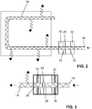
- the couplers are in Figures 2 and 3 presented in detail.
- the coupling is carried out by a fixed connector 22 with a lens 24.
- the lens 24 and the ends 26 and 28 of the sections 14 and 18 connected to one another are fixed in a coupler housing 30.
- springs or other fixing elements 32 and 34 are provided as a socket for the ends 26 and 28. The position of the ends 26 and 28 is thus well fixed.
- the lens 24 ensures that the light is well coupled into the next section 14 even in the event of adjustment tolerances or changes in position.
- the side light fibers 12 and 14, the couplers 20 and 22 and the end light fibers 16 and 18 form an optical waveguide arrangement with sections 12 and 16 or 14 and 18 coupled to one another produce.
- the fiber cladding allows the light to exit from the side, while in other sections the light guided by the light guide is completely reflected and cannot exit.
- the light is guided via the end light fibers 16 and 18 from the outside to the sections formed from the side light light fibers 12 and 14 so that they are not perceptible from the outside.
- all sections are knitted into the knitted fabric. This does not affect the textile appearance of the knitted fabric.
- Couplers 36 and 38 are provided at the lower end of the end light fibers 16 and 18. Light is coupled into the light guide arrangement at the couplers 36 and 40.
- the couplers 36 and 38 form part of an electronic component 40.
- the electronic component 40 comprises LEDs 42 and 44. The light from the LED 42 is coupled into the end light fiber 16 at the coupler 36. The light from the LED 44 is coupled into the end light fiber 18 at the coupler 38.
- the LEDs 42 and 44 are each provided with a cooling lug 54, of which for the sake of clarity in the illustration in FIG Figure 4 only one is shown. With the cooling vane 54, heat generated by the LED can be dissipated to the outside.
- the LEDs 42 and 44 are controlled by a driver 46 and supplied with electrical energy from an accumulator 48.
- Accumulators 48 of this type are also known under the term “power bank” and comprise accumulators with connections via which the charging and provision of electrical energy takes place.
- the connection between the accumulator 48 and the electronic component 40 can take place via a detachable plug connection, for example via USB or the like. However, a magnetic connection can also be established.
- the driver 46 receives control signals via a receiver 50 with a chip antenna 52.
- the driver 46 then does not need any input means, for example a keyboard or the like, or a display.
- the entire arrangement of couplers 36 and 38, LEDs 42, 44, cooling lugs 54, driver 46 and receiver 50 is accommodated in a silicone potting 56.
- the components contained in the silicone potting 56 are housed together in the textile.
- there is one for this closed pocket provided, in which the part 56 is received. Only the batteries 48 are detachably arranged in the pocket 58. These can be removed before washing and / or for charging or replacement.
- buttons 60 are designed, for example, as textile buttons and attached to the wrist, as in FIG Figure 1 shown. It goes without saying that any other button can also be used, for example on the handlebar or the like.
- the button arrangement 60 comprises a button 62.
- a circuit 64 can be closed with the button 62.
- the current flowing through this is converted via electronics 66 into a signal which is transmitted to the receiver 50 by means of a transmitter 68.
- the electronics 66 cooperate with the driver 46.
- the light beam generated by the LED is interrupted, for example, at regular intervals.
- FIG 5 a variant of the side light fiber is also illustrated.
- the light from the end light fiber 16 is guided via a partially transparent mirror 82 in a coupler 84. Part of the light is reflected in at mirror 82 Figure 5 reflected and coupled into a side light fiber section 86. As with all the side light fibers described here, the light is partially emitted. This is represented by arrows 88.
- the light emerging at the end 90 is again passed through the mirror 82. There it is at least partially reflected and returns to the side light fiber.
- the light transmitted from the end light fiber 16 at the mirror 82 is also directed back onto the mirrored surface and reflected upwards. There it enters the side light fiber at the end 90.
- the use of such an arrangement enables the light to be distributed particularly evenly over the side light fiber, so that all the parts emit evenly.
- FIG 7 and Figure 8 is illustrated how the light guides 16 are integrated into the knitted fabric.
- the textile itself is produced in a conventional manner with a basic thread 92.
- the optical fibers can be knitted or embroidered into the textile.
- the fixation is advantageously carried out with transparent yarns, for example with transparent polyester yarns.
- the fibers are fed from the bobbin into the knitted fabric using inlaid thread guides. This is for example in DE 20 2013 005 116 U1 described.
- light guides that are integrated into a textile is not limited to a turn signal system on clothing.
- Self-illuminating upholstery or upholstery sections and items of clothing can also be realized in this way. These then serve, for example, to attract attention, as a fashion accessory or to improve safety, for example in traffic or in unlit rooms.
- a stiff textile material is provided, which can be used, for example, as a lampshade, furniture accessory, security light or the like.
- the use as edge protection, for the individualization of parts, housings, instruments, dashboards, building or vehicle interiors and the like is possible.
- thermoplastic yarn 94 can be knitted in, woven in or otherwise worked in together with the light guide 16. This is also in Figure 8 illustrated.
- the textile 100 is pressed into a desired shape under the action of heat, for example at 160 °.
- molds 96 and 98 are used, which are shown schematically in Figure 9 are illustrated.
- the thermoplastic yarn 94 and the light guide 16 become stiff and lose their flexibility. It goes without saying that the temperature depends on the material and can vary up or down. After cooling, there is a two- or three-dimensional body with a textile look. The property of the luminaire can only be recognized when light is coupled into the light guide. Otherwise, the three-dimensional body looks like any other textile body that has been stiffened in one way or another.
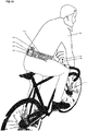
- FIGS 9 to 13 illustrate an application example in which side light fibers are used as turn signals for cyclists.
- a driver 102 is riding a bicycle 100.
- the driver 102 is wearing a belt 104.
- the belt can, for example, be in three different belt lengths XS ... S; M ... L and XL ... XXL are available for a rough classification.
- a unit 106 with a driver 108 and a power bank 110 is attached to the belt.
- the LEDs are connected to the driver / receiver 108 via a cable. This has the advantage that light can be coupled in from both sides of the fiber. This causes the fibers to shine brighter and more homogeneously.
- Figure 11 shows the fiber 128 designed as a left turn signal and the fiber 130 designed as a right turn signal.
- the fibers 128 and 130 are incorporated into the belt with a fastener 132.
- the fastener can be designed, for example, as a Velcro fastener and is thus adapted to the body size.
- the belt can, for example, be made from a rib knit 134 which has a lining 136. The rib knit ensures elasticity.
- the light guides have a diameter of 1.5 mm and are knitted in as shown.
- the LEDs are connected to driver 108 via a conventional cable.
- the driver 108 is sewn into the unit 106 on the inside of the belt 104.
- the light guides can be covered with a transparent film.
- two light guides 150 and 152 are provided for white light.
- Two segments 128 and 130 are also provided as indicators.
- the indicators 128 and 130 light up intermittently.
- Two LEDs are connected at both ends of the light guides 150 and 152 for continuous light. All white light LEDs light up at the same time.
- All indicators 128 and 130 can be actuated to indicate braking. Here there is an option to switch the color from red to yellow.
- An antenna 112 receives signals from a transmitter 116, which is provided on a remote control 114.
- the belt 104 is used as a headband and accordingly has different dimensions and textile properties.
- Remote control 114 is attached to the handlebar of bicycle 100.
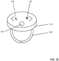
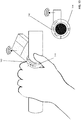
- Figure 12 and Figure 13 illustrate various variants of such a remote control 114.
- Figure 12 shows a remote control with a housing 118.
- the housing 118 is fastened to the handlebar of the bicycle 100 with fastening rings 120 in a manner similar to a bell.
- the remote control has three buttons 122, 124 and 126.
- the buttons 122 and 124 trigger the flashing to the right or left.
- the button 126 triggers a blinking of both fibers.
- Figure 13 illustrates a remote control 140, which is designed as a rotary element. Rotation of an actuating element 142 around a fixed housing 144 serves to adjust the turn signal.
- the belt / headband can be designed with different functionalities and different efforts.
- a light belt In the simplest product form, only a light belt is used, which only emits white continuous light. There is also no need for remote control.
- the light is turned on by connecting the power bank to the driver.
- the wireless remote-controlled light belt provides a more convenient solution.
- the turn signals and stop light can be controlled via IMS bands at 2.4 GHz and the steady light can be switched on and off.
- the brake light can also be triggered by double-clicking on one of the turn signal buttons.
Landscapes
- Engineering & Computer Science (AREA)
- General Engineering & Computer Science (AREA)
- Physics & Mathematics (AREA)
- General Physics & Mathematics (AREA)
- Optics & Photonics (AREA)
- Knitting Of Fabric (AREA)
- Professional, Industrial, Or Sporting Protective Garments (AREA)
Applications Claiming Priority (1)
| Application Number | Priority Date | Filing Date | Title |
|---|---|---|---|
| DE102018127753.9A DE102018127753A1 (de) | 2018-11-07 | 2018-11-07 | Leuchtenanordnung für Textilien |
Publications (1)
| Publication Number | Publication Date |
|---|---|
| EP3650752A1 true EP3650752A1 (fr) | 2020-05-13 |
Family
ID=65991703
Family Applications (1)
| Application Number | Title | Priority Date | Filing Date |
|---|---|---|---|
| EP19165393.0A Withdrawn EP3650752A1 (fr) | 2018-11-07 | 2019-03-27 | Dispositif d'éclairage pour textiles |
Country Status (2)
| Country | Link |
|---|---|
| EP (1) | EP3650752A1 (fr) |
| DE (1) | DE102018127753A1 (fr) |
Cited By (3)
| Publication number | Priority date | Publication date | Assignee | Title |
|---|---|---|---|---|
| US11427945B2 (en) | 2016-08-10 | 2022-08-30 | Inteva Products Europe Gmbh | Arrangement comprising a visible seam and a lighting apparatus, use thereof, and method for producing the arrangement |
| US11958406B2 (en) | 2020-11-18 | 2024-04-16 | Inteva Products, Llc | Illuminated stitching that provides vehicle status |
| EP4307952A4 (fr) * | 2021-03-19 | 2025-03-12 | Coast Cutlery Co. | Gilet de sécurité à tubes lumineux |
Families Citing this family (1)
| Publication number | Priority date | Publication date | Assignee | Title |
|---|---|---|---|---|
| DE102021111323B4 (de) | 2021-05-03 | 2024-02-08 | bt2work GmbH | Elektronisches Multifunktionssystem für textile Anwendungen mit interaktiven Sensorsystem (Offboard und Onboard) |
Citations (9)
| Publication number | Priority date | Publication date | Assignee | Title |
|---|---|---|---|---|
| US4234907A (en) | 1979-01-29 | 1980-11-18 | Maurice Daniel | Light emitting fabric |
| US4727603A (en) * | 1987-03-06 | 1988-03-01 | Howard Rebecca L | Garment with light-conducting fibers |
| EP0359450A2 (fr) | 1988-09-12 | 1990-03-21 | Lumitex Inc. | Panneaux éclairants et procédé de fabrication |
| WO2005124015A1 (fr) * | 2004-06-18 | 2005-12-29 | Cheon-Soo Jeong | Textile a fibres optiques |
| KR100712737B1 (ko) * | 2005-06-21 | 2007-05-04 | 연세대학교 산학협력단 | 색상변화기능을 갖는 광섬유직물제품 |
| US20140078773A1 (en) * | 2012-09-17 | 2014-03-20 | Noxgear, Llc | Illuminated vest |
| DE202013005116U1 (de) | 2013-06-06 | 2014-09-08 | Strickmanufaktur Zella Gmbh | Textiles piezo-elektrisches Sensor-/Aktuatorelement |
| US20160146450A1 (en) * | 2014-11-26 | 2016-05-26 | Radiant Enterprises, LLC | Flexible water-resistant optical fiber light display |
| EP3073192A1 (fr) * | 2015-03-27 | 2016-09-28 | SCILIF s.r.o. | Équipement de vêtement de protection actif ou moyen d'irradiation de ligne |
Family Cites Families (6)
| Publication number | Priority date | Publication date | Assignee | Title |
|---|---|---|---|---|
| DE3525838A1 (de) * | 1985-07-02 | 1987-01-22 | Joachim Zappe | Verfahren zum erzielen von leuchteffekten an werkstoffen und daraus gefertigten gegenstaenden |
| DE102005008444B4 (de) * | 2005-02-24 | 2007-11-15 | Männel GBV GmbH | Bekleidungsstück mit Beleuchtung |
| KR101142192B1 (ko) * | 2010-11-05 | 2012-05-14 | 주식회사 엘티전자 | 광섬유 직물 디스플레이를 구비한 스마트 의류 제어시스템 및 그의 스마트 폰을 연동한 제어방법 |
| DE102014110120A1 (de) * | 2014-07-18 | 2016-01-21 | Deutsche Telekom Ag | Seitenlichtfaser |
| US10076142B2 (en) * | 2015-08-13 | 2018-09-18 | F.R.E.D. Llc | Durable reflective safety apparel with active laser illumination |
| DE102016223335A1 (de) * | 2016-11-24 | 2018-05-24 | Viessmann Werke Gmbh & Co Kg | Flächenheizgewebe mit hydraulischen Heizrohren und Seitenlichtfasern |
-
2018
- 2018-11-07 DE DE102018127753.9A patent/DE102018127753A1/de not_active Withdrawn
-
2019
- 2019-03-27 EP EP19165393.0A patent/EP3650752A1/fr not_active Withdrawn
Patent Citations (9)
| Publication number | Priority date | Publication date | Assignee | Title |
|---|---|---|---|---|
| US4234907A (en) | 1979-01-29 | 1980-11-18 | Maurice Daniel | Light emitting fabric |
| US4727603A (en) * | 1987-03-06 | 1988-03-01 | Howard Rebecca L | Garment with light-conducting fibers |
| EP0359450A2 (fr) | 1988-09-12 | 1990-03-21 | Lumitex Inc. | Panneaux éclairants et procédé de fabrication |
| WO2005124015A1 (fr) * | 2004-06-18 | 2005-12-29 | Cheon-Soo Jeong | Textile a fibres optiques |
| KR100712737B1 (ko) * | 2005-06-21 | 2007-05-04 | 연세대학교 산학협력단 | 색상변화기능을 갖는 광섬유직물제품 |
| US20140078773A1 (en) * | 2012-09-17 | 2014-03-20 | Noxgear, Llc | Illuminated vest |
| DE202013005116U1 (de) | 2013-06-06 | 2014-09-08 | Strickmanufaktur Zella Gmbh | Textiles piezo-elektrisches Sensor-/Aktuatorelement |
| US20160146450A1 (en) * | 2014-11-26 | 2016-05-26 | Radiant Enterprises, LLC | Flexible water-resistant optical fiber light display |
| EP3073192A1 (fr) * | 2015-03-27 | 2016-09-28 | SCILIF s.r.o. | Équipement de vêtement de protection actif ou moyen d'irradiation de ligne |
Cited By (4)
| Publication number | Priority date | Publication date | Assignee | Title |
|---|---|---|---|---|
| US11427945B2 (en) | 2016-08-10 | 2022-08-30 | Inteva Products Europe Gmbh | Arrangement comprising a visible seam and a lighting apparatus, use thereof, and method for producing the arrangement |
| US12392066B2 (en) | 2016-08-10 | 2025-08-19 | Inteva Products Europe Gmbh | Arrangement comprising a visible seam and a lighting apparatus, use thereof, and method for producing the arrangement |
| US11958406B2 (en) | 2020-11-18 | 2024-04-16 | Inteva Products, Llc | Illuminated stitching that provides vehicle status |
| EP4307952A4 (fr) * | 2021-03-19 | 2025-03-12 | Coast Cutlery Co. | Gilet de sécurité à tubes lumineux |
Also Published As
| Publication number | Publication date |
|---|---|
| DE102018127753A1 (de) | 2020-05-07 |
Similar Documents
| Publication | Publication Date | Title |
|---|---|---|
| EP3650752A1 (fr) | Dispositif d'éclairage pour textiles | |
| AU2016100211A4 (en) | Woven display | |
| US10273600B1 (en) | Devices having fabric with adjustable appearance | |
| US5424922A (en) | Fiber optic apparel and safety gear | |
| EP3868234B1 (fr) | Vêtement avec fonction de signalisation en cas de détection d' objet | |
| US9808041B2 (en) | Cap or similar headwear having luminous means incorporated in the decorative and/or in the promotional elements | |
| DE29808222U1 (de) | Bekleidungsstück, insbesondere Mütze | |
| EP2917391A1 (fr) | Gaine textile contenant une fibre optique à émission latérale | |
| US10900154B2 (en) | Knit fabric with electrical components | |
| DE102005007598A1 (de) | Bekleidungsstück | |
| US20060092625A1 (en) | Electronic luminescent clothing and tapes | |
| AT526841B1 (de) | Anzeigeeinrichtung in einem Textil mit einer Signaleinrichtung für einen verbesserten Schutz im Straßenverkehr und bei sportlicher Betätigung | |
| WO2004010047A1 (fr) | Lampe de poche | |
| DE102004039765A1 (de) | Textilerzeugnis mit einfach abnehmbaren elektrischen Bauteilen | |
| KR100712737B1 (ko) | 색상변화기능을 갖는 광섬유직물제품 | |
| EP3740043A1 (fr) | Produit textile | |
| DE3129097A1 (de) | Reitgerte | |
| DE102021129944A1 (de) | Textiles Produkt | |
| DE102021001208B4 (de) | Flexibles Flächengebilde mit beleuchteten Flächenbereichen als Anzeigevorrichtung | |
| EP4483352A1 (fr) | Article textile doté d'un moyen d'éclairage électrique | |
| KR20130131848A (ko) | 전도사를 이용한 비기판형의 안전의류용 led 발광장치 및 이를 적용한 안전의류 | |
| KR200238043Y1 (ko) | 광섬유를 이용한 장신구 | |
| WO2004008902A1 (fr) | Porte-cles | |
| DE102014014506A1 (de) | Fanschal | |
| DE9421941U1 (de) | Leuchtartikel |
Legal Events
| Date | Code | Title | Description |
|---|---|---|---|
| PUAI | Public reference made under article 153(3) epc to a published international application that has entered the european phase |
Free format text: ORIGINAL CODE: 0009012 |
|
| STAA | Information on the status of an ep patent application or granted ep patent |
Free format text: STATUS: THE APPLICATION HAS BEEN PUBLISHED |
|
| AK | Designated contracting states |
Kind code of ref document: A1 Designated state(s): AL AT BE BG CH CY CZ DE DK EE ES FI FR GB GR HR HU IE IS IT LI LT LU LV MC MK MT NL NO PL PT RO RS SE SI SK SM TR |
|
| AX | Request for extension of the european patent |
Extension state: BA ME |
|
| 18D | Application deemed to be withdrawn |
Effective date: 20201114 |