EP3650772A1 - Climatiseur et système de climatisation - Google Patents
Climatiseur et système de climatisation Download PDFInfo
- Publication number
- EP3650772A1 EP3650772A1 EP17917165.7A EP17917165A EP3650772A1 EP 3650772 A1 EP3650772 A1 EP 3650772A1 EP 17917165 A EP17917165 A EP 17917165A EP 3650772 A1 EP3650772 A1 EP 3650772A1
- Authority
- EP
- European Patent Office
- Prior art keywords
- air
- heat exchanger
- indoor
- conditioning apparatus
- refrigerant
- Prior art date
- Legal status (The legal status is an assumption and is not a legal conclusion. Google has not performed a legal analysis and makes no representation as to the accuracy of the status listed.)
- Granted
Links
Images

Classifications
-
- F—MECHANICAL ENGINEERING; LIGHTING; HEATING; WEAPONS; BLASTING
- F24—HEATING; RANGES; VENTILATING
- F24F—AIR-CONDITIONING; AIR-HUMIDIFICATION; VENTILATION; USE OF AIR CURRENTS FOR SCREENING
- F24F12/00—Use of energy recovery systems in air conditioning, ventilation or screening
- F24F12/001—Use of energy recovery systems in air conditioning, ventilation or screening with heat-exchange between supplied and exhausted air
- F24F12/006—Use of energy recovery systems in air conditioning, ventilation or screening with heat-exchange between supplied and exhausted air using an air-to-air heat exchanger
-
- F—MECHANICAL ENGINEERING; LIGHTING; HEATING; WEAPONS; BLASTING
- F24—HEATING; RANGES; VENTILATING
- F24F—AIR-CONDITIONING; AIR-HUMIDIFICATION; VENTILATION; USE OF AIR CURRENTS FOR SCREENING
- F24F11/00—Control or safety arrangements
- F24F11/0008—Control or safety arrangements for air-humidification
-
- F—MECHANICAL ENGINEERING; LIGHTING; HEATING; WEAPONS; BLASTING
- F24—HEATING; RANGES; VENTILATING
- F24F—AIR-CONDITIONING; AIR-HUMIDIFICATION; VENTILATION; USE OF AIR CURRENTS FOR SCREENING
- F24F11/00—Control or safety arrangements
- F24F11/70—Control systems characterised by their outputs; Constructional details thereof
- F24F11/72—Control systems characterised by their outputs; Constructional details thereof for controlling the supply of treated air, e.g. its pressure
- F24F11/79—Control systems characterised by their outputs; Constructional details thereof for controlling the supply of treated air, e.g. its pressure for controlling the direction of the supplied air
-
- F—MECHANICAL ENGINEERING; LIGHTING; HEATING; WEAPONS; BLASTING
- F24—HEATING; RANGES; VENTILATING
- F24F—AIR-CONDITIONING; AIR-HUMIDIFICATION; VENTILATION; USE OF AIR CURRENTS FOR SCREENING
- F24F11/00—Control or safety arrangements
- F24F11/70—Control systems characterised by their outputs; Constructional details thereof
- F24F11/80—Control systems characterised by their outputs; Constructional details thereof for controlling the temperature of the supplied air
- F24F11/86—Control systems characterised by their outputs; Constructional details thereof for controlling the temperature of the supplied air by controlling compressors within refrigeration or heat pump circuits
-
- F—MECHANICAL ENGINEERING; LIGHTING; HEATING; WEAPONS; BLASTING
- F24—HEATING; RANGES; VENTILATING
- F24F—AIR-CONDITIONING; AIR-HUMIDIFICATION; VENTILATION; USE OF AIR CURRENTS FOR SCREENING
- F24F12/00—Use of energy recovery systems in air conditioning, ventilation or screening
- F24F12/001—Use of energy recovery systems in air conditioning, ventilation or screening with heat-exchange between supplied and exhausted air
- F24F2012/007—Use of energy recovery systems in air conditioning, ventilation or screening with heat-exchange between supplied and exhausted air using a by-pass for bypassing the heat-exchanger
-
- F—MECHANICAL ENGINEERING; LIGHTING; HEATING; WEAPONS; BLASTING
- F24—HEATING; RANGES; VENTILATING
- F24F—AIR-CONDITIONING; AIR-HUMIDIFICATION; VENTILATION; USE OF AIR CURRENTS FOR SCREENING
- F24F2110/00—Control inputs relating to air properties
- F24F2110/10—Temperature
-
- F—MECHANICAL ENGINEERING; LIGHTING; HEATING; WEAPONS; BLASTING
- F24—HEATING; RANGES; VENTILATING
- F24F—AIR-CONDITIONING; AIR-HUMIDIFICATION; VENTILATION; USE OF AIR CURRENTS FOR SCREENING
- F24F2110/00—Control inputs relating to air properties
- F24F2110/20—Humidity
-
- F—MECHANICAL ENGINEERING; LIGHTING; HEATING; WEAPONS; BLASTING
- F24—HEATING; RANGES; VENTILATING
- F24F—AIR-CONDITIONING; AIR-HUMIDIFICATION; VENTILATION; USE OF AIR CURRENTS FOR SCREENING
- F24F3/00—Air-conditioning systems in which conditioned primary air is supplied from one or more central stations to distributing units in the rooms or spaces where it may receive secondary treatment; Apparatus specially designed for such systems
- F24F3/044—Systems in which all treatment is given in the central station, i.e. all-air systems
-
- F—MECHANICAL ENGINEERING; LIGHTING; HEATING; WEAPONS; BLASTING
- F24—HEATING; RANGES; VENTILATING
- F24F—AIR-CONDITIONING; AIR-HUMIDIFICATION; VENTILATION; USE OF AIR CURRENTS FOR SCREENING
- F24F3/00—Air-conditioning systems in which conditioned primary air is supplied from one or more central stations to distributing units in the rooms or spaces where it may receive secondary treatment; Apparatus specially designed for such systems
- F24F3/12—Air-conditioning systems in which conditioned primary air is supplied from one or more central stations to distributing units in the rooms or spaces where it may receive secondary treatment; Apparatus specially designed for such systems characterised by the treatment of the air otherwise than by heating and cooling
- F24F3/14—Air-conditioning systems in which conditioned primary air is supplied from one or more central stations to distributing units in the rooms or spaces where it may receive secondary treatment; Apparatus specially designed for such systems characterised by the treatment of the air otherwise than by heating and cooling by humidification; by dehumidification
-
- Y—GENERAL TAGGING OF NEW TECHNOLOGICAL DEVELOPMENTS; GENERAL TAGGING OF CROSS-SECTIONAL TECHNOLOGIES SPANNING OVER SEVERAL SECTIONS OF THE IPC; TECHNICAL SUBJECTS COVERED BY FORMER USPC CROSS-REFERENCE ART COLLECTIONS [XRACs] AND DIGESTS
- Y02—TECHNOLOGIES OR APPLICATIONS FOR MITIGATION OR ADAPTATION AGAINST CLIMATE CHANGE
- Y02B—CLIMATE CHANGE MITIGATION TECHNOLOGIES RELATED TO BUILDINGS, e.g. HOUSING, HOUSE APPLIANCES OR RELATED END-USER APPLICATIONS
- Y02B30/00—Energy efficient heating, ventilation or air conditioning [HVAC]
- Y02B30/56—Heat recovery units
-
- Y—GENERAL TAGGING OF NEW TECHNOLOGICAL DEVELOPMENTS; GENERAL TAGGING OF CROSS-SECTIONAL TECHNOLOGIES SPANNING OVER SEVERAL SECTIONS OF THE IPC; TECHNICAL SUBJECTS COVERED BY FORMER USPC CROSS-REFERENCE ART COLLECTIONS [XRACs] AND DIGESTS
- Y02—TECHNOLOGIES OR APPLICATIONS FOR MITIGATION OR ADAPTATION AGAINST CLIMATE CHANGE
- Y02B—CLIMATE CHANGE MITIGATION TECHNOLOGIES RELATED TO BUILDINGS, e.g. HOUSING, HOUSE APPLIANCES OR RELATED END-USER APPLICATIONS
- Y02B30/00—Energy efficient heating, ventilation or air conditioning [HVAC]
- Y02B30/70—Efficient control or regulation technologies, e.g. for control of refrigerant flow, motor or heating
Definitions
- the present invention relates to an air-conditioning apparatus that processes an outside-air load, and an air-conditioning system including the air-conditioning apparatus.
- Patent Literature 1 describes an air-conditioning apparatus including an air supply passage and an air exhaust passage that intersect each other at a heat exchanger.
- the air-conditioning device includes a humidifier provided in part of the air supply passage that is located downstream of the heat exchanger in a direction where air is sent, a bypass opening that causes the air exhaust passage to communicate with the air supply passage between the heat exchanger and the humidifier, the air exhaust passage being located upstream of the heat exchanger in the air-sending direction, an opening/closing unit that opens and closes the bypass opening, a unit that detects the humidity of indoor space, and a control unit that controls driving of the opening/closing unit in accordance with the detected humidity.
- Patent Literature 1 Japanese Patent No. 4656357
- Patent Literature 1 In the air-conditioning apparatus described in Patent Literature 1, part of warm air in indoor space, which has not yet passed through the heat exchanger, flows to the humidifier through the bypass opening, and a humidification performance can thus be improved. In the case where a heating unit that heats air is provided upstream of the humidifier, heated air can be caused to flow through the humidifier. Therefore, the humidification performance of the air-conditioning apparatus can be further improved, and an indoor humidity can be promptly raised.
- Patent Literature 1 does not specifically describe a configuration in which the heating unit is provided upstream of the humidifier. Generally, when air is heated in a region located upstream of the humidifier, the temperature of air that is supplied into the indoor space is increased, and an indoor temperature is unnecessarily increased.
- the present invention has been made to solve the above problem, and an object of the invention is to provide an air-conditioning apparatus and an air-conditioning system that are capable of promptly increasing the humidity of indoor space while preventing the temperature of the indoor space from being unnecessarily increased.
- An air-conditioning apparatus includes a housing in which an air supply passage and air exhaust passage are provided, the air supply passage allowing flow of outdoor air to be supplied into an indoor space, the air exhaust passage allowing flow of indoor air to be exhausted to the outside of the indoor space; an air-to-air heat exchanger provided in the housing to transfer at least sensible heat between the outdoor air and the indoor air; an air-to-refrigerant heat exchanger provided in an air supply passage and forming part of a refrigerant circuit that circulates refrigerant, the air-to-refrigerant heat exchanger being provided to transfer heat between the outdoor air and the refrigerant; a humidifying device provided in part of the air supply passage that is located downstream of the air-to-refrigerant heat exchanger, the humidifying device being provided to humidify the outdoor air; a communication passage that causes part of the air exhaust passage that is located upstream of the air-to-air heat exchanger and part of the air supply passage that is located downstream of the air-to-air-
- An air-conditioning system is an air-conditioning system including a first air-conditioning apparatus that processes an outside-air load, and supplies outdoor air into an indoor space; a second air-conditioning apparatus that processes a load inside the indoor space; and a system controller that controls the first air-conditioning apparatus and the second air-conditioning apparatus.
- the first air-conditioning apparatus is the air-conditioning apparatus according to the above-described embodiment of the present invention; the first air-conditioning apparatus is capable of performing a heating and humidifying operation in which the air-to-refrigerant heat exchanger operates as a condenser and the humidifying device performs humidification; the second air-conditioning apparatus includes a load-side heat exchanger forming part of a refrigerant circuit that circulates refrigerant; the second air-conditioning apparatus is capable of performing a cooling operation in which the load-side heat exchanger operates as an evaporator; and the system controller increases an evaporating temperature of the refrigerant circuit of the second air-conditioning apparatus, in the case where the first air-conditioning apparatus is performing the heating and humidifying operation, and the second air-conditioning apparatus is performing the cooling operation.
- the opening/closing device Since the operation of the opening/closing device is controlled, part of indoor air whose humidity is relatively high as compared with outdoor air can be made to flow into the air supply passage through the communication passage, and to be supplied along with the outdoor air into the indoor space. Furthermore, since the refrigerant temperature in the air-to-refrigerant heat exchanger is also controlled, it is possible to raise the temperature of air in a region located upstream of the humidifying device. Therefore, according to the embodiments of the present invention, the indoor humidity can be further promptly raised. Furthermore, the refrigerant temperature in the air-to-refrigerant heat exchanger is controlled based on the indoor temperature. Therefore, according to the embodiments of the present invention, the indoor temperature can be prevented from being unnecessarily raised.
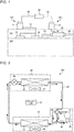
- Fig. 1 is a schematic diagram illustrating a configuration of an air-conditioning system including a first air-conditioning apparatus 201 according to Embodiment 1.
- the air-conditioning system includes a first air-conditioning apparatus 201 including an outside-air processing unit 20 and an outdoor unit 21, and a second air-conditioning apparatus 202 including a plurality of indoor units 10 and an outdoor unit 11.
- the outside-air processing unit 20 and the indoor units 10 are provided in space 101 above a ceiling.
- the outside-air processing unit 20 is connected to the outdoor unit 21 by a refrigerant pipe 22.
- the plurality of indoor units 10 are connected to the outdoor unit 11 by refrigerant pipes 12.
- the outdoor units 11 and 21 are provided outdoors.
- a heat load in indoor space 102 is subjected mainly to processing by the indoor units 10
- an outside-air load is subjected mainly to processing by the outside-air processing unit 20.
- the outside-air processing unit 20 may also be referred to as an outside-air conditioning unit.
- Fig. 1 illustrates a single outside-air processing unit 20, but the number of outside-air processing units 20 may be two or more. Furthermore, Fig. 1 illustrates two indoor units 10, but the number of indoor units 10 may be one, or may be three or more.
- the outside-air processing unit 20 communicates with the indoor space 102 through an indoor duct 23.
- the indoor duct 23 includes an air supply duct that allows air from the outside-air processing unit 20 to be supplied into the indoor space, and an air return duct that allows air in the indoor space to return to the outside-air processing unit 20.
- the outside-air processing unit 20 communicates with outdoor space through an outdoor duct 24.
- the outdoor duct 24 includes an outside-air duct that allows outdoor air to be introduced into the outside-air processing unit 20, and an air exhaust duct that allows air from the outside-air processing unit 20 to be exhausted to the outdoor space.
- the air-conditioning system includes a system controller 30 that controls the first air-conditioning apparatus 201 and the second air-conditioning apparatus 202.
- the system controller 30 includes a microcomputer including a CPU, a ROM, a RAM, an I/O port, etc.
- the system controller 30 is connected to the control unit 31 (not illustrated in Fig. 1 ) that controls the first air-conditioning apparatus 201 and a control unit that controls the second air-conditioning apparatus 202 by respective communication lines 32.
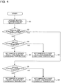
- Fig. 2 is a refrigerant circuit diagram illustrating a configuration of the first air-conditioning apparatus 201 according to Embodiment 1.
- the first air-conditioning apparatus 201 includes a refrigerant circuit 40 that circulates refrigerant, and the control unit 31 that controls the refrigerant circuit 40.
- a compressor 41, a four-way valve 42, a heat-source-side heat exchanger 43, an expansion valve 44, and a load-side heat exchanger 45 are sequentially connected.
- the compressor 41, the four-way valve 42, and the heat-source-side heat exchanger 43 are housed in the outdoor unit 21, and in addition an outdoor fan 46 that sends air to the heat-source-side heat exchanger 43 is also housed in the outdoor unit 21.
- the expansion valve 44 and the load-side heat exchanger 45 are housed in the outside-air processing unit 20, and in addition an air supply fan 47 that sends air to the load-side heat exchanger 45 is also housed in in the outside-air processing unit 20.
- the compressor 41 is provided with a frequency adjusting unit 49 that adjusts a driving frequency of the compressor 41 under control by the control unit 31. That is, the driving frequency of the compressor 41 is controlled by the control unit 31.
- the four-way valve 42 is provided to switch the flow of refrigerant between the flow of refrigerant in a cooling operation and the flow of refrigerant in a heating operation, under the control by the control unit 31. Thereby, in the refrigerant circuit 40, the operation to be performed can be switched between the cooling operation in which the load-side heat exchanger 45 operates as an evaporator and the heating operation in which the load-side heat exchanger 45 operates as a condenser.
- arrows indicates the flow direction of the refrigerant during the cooling operation.
- the heat-source-side heat exchanger 43 is an air-to-refrigerant heat exchanger that transfers heat between air sent by the outdoor fan 46 and refrigerant that flows in the air-to-refrigerant heat exchanger.
- the expansion valve 44 is a valve that reduces the pressure of refrigerant to expand the refrigerant. As the expansion valve 44, an electronic expansion valve whose opening degree can be adjusted under control by the control unit 31 is used.
- the load-side heat exchanger 45 is an air-to-refrigerant heat exchanger that transfers heat between air sent by the air supply fan 47 and refrigerant in the air-to-refrigerant heat exchanger.
- An evaporating temperature sensor 48 is provided on a suction side of the compressor 41 of the refrigerant circuit 40.
- the evaporating temperature sensor 48 measures an evaporating temperature of refrigerant, and outputs a signal corresponding to a value obtained by measurement by the evaporating temperature sensor 48 to the control unit 31.
- the control unit 31 includes a microcomputer including a CPU, a ROM, a RAM, an I/O port, etc.
- the control unit 31 controls the compressor 41, the four-way valve 42, the expansion valve 44, the outdoor fan 46, the air supply fan 47, etc. based on commands from the system controller 30, output signals from various sensors including the evaporating temperature sensor 48, and other signals.
- the control unit 31 may be provided at the outdoor unit 21 or at the outside-air processing unit 20.
- the control unit 31 may further include an outdoor-unit control unit provided at the outdoor unit 21, and an outside-air processing unit control unit provided at the outside-air processing unit 20 and capable of communicating with the outdoor-unit control unit.
- Fig. 3 is a schematic diagram illustrating a configuration of the outside-air processing unit 20 of the first air-conditioning apparatus 201 according to Embodiment 1.
- the outside-air processing unit 20 includes a housing 50.
- an air supply passage 51 and an air exhaust passage 52 are provided in the housing 50.
- the air supply passage 51 is provided to circulate outdoor air to be supplied into the indoor space
- the air exhaust passage 52 is provided to circulate indoor air to be exhausted to the outside.
- the housing 50 is partitioned into the air supply passage 51 and the air exhaust passage 52, except for a communication passage 60 which will be described later.
- an outside-air introduction port 53 is provided to introduce outdoor air into the air supply passage 51.
- the outside-air introduction port 53 communicates with the outdoor space through the outside-air duct.
- outdoor air that is introduced from the outdoor space through the outside-air introduction port 53 may be referred to as "outside air OA”.
- an air inlet 54 is provided to supply outdoor air into the indoor space.
- the air inlet 54 communicates with the indoor space through the air supply duct.
- supply air SA outdoor air that is supplied into the indoor space through the air inlet 54
- An air return port 55 that allows indoor air to be introduced into the air exhaust passage 52 is formed at an upstream end of the air exhaust passage 52.
- the air return port 55 is provided to connect with the indoor space through the air return duct.
- indoor air that is introduced from the indoor space through the air return port 55 may be referred to as "return air RA”.
- An air exhaust port 56 that allows indoor air to be exhausted to the outdoor space is provided at a downstream end of the air exhaust passage 52.
- the air exhaust port 56 is provided to connect with the outdoor space through the air exhaust duct.
- indoor air that is exhausted to the outdoor space through the air exhaust port 56 may be referred to as "exhaust air EA.”
- a total heat exchanger 57 is provided in the housing 50.
- the total heat exchanger 57 is provided to transfer sensible heat and latent heat between outdoor air that flows through the air supply passage 51 and indoor air that flows through the air exhaust passage 52.
- a static total heat exchanger or a rotary total heat exchanger can be used as the total heat exchanger 57.
- the operation of the total heat exchanger 57 is controlled by the control unit 31.
- an upstream side of the air exhaust passage 51 that is located upstream of the total heat exchanger 57 may be referred to as an upstream-side air supply passage 51a.
- a downstream side of the air exhaust passage 51 that is located downstream of the total heat exchanger 57 may be referred to as a downstream-side air supply passage 51b.
- An upstream side of the air exhaust passage 52 that is located upstream of the total heat exchanger 57 may be referred to as an upstream-side air exhaust passage 52a.
- a downstream side of the air exhaust passage 52 that is located downstream of the total heat exchanger 57 may be referred to as a downstream-side air exhaust passage 52b.
- the air supply fan 47 is provided in the upstream-side air supply passage 51a.
- the air supply fan 47 is provided to produce in the air supply passage 51, a flow of air in a direction from the outside-air introduction port 53 toward the air inlet 54.
- the operation of the air supply fan 47 is controlled by the control unit 31.
- the load-side heat exchanger 45 forming part of the refrigerant circuit 40 is provided.
- the load-side heat exchanger 45 operates as an evaporator that cools air during the cooling operation, and operates as a condenser that heats air during the heating operation.
- a humidifying device 58 is provided on a downstream side of the downstream-side air supply passage 51b that is located downstream of the load-side heat exchanger 45.
- the humidifying device 58 for example, an evaporative humidifier of a moisture permeable membrane type or of a drip evaporative type is used.
- the operation of the humidifying device 58 is controlled by the control unit 31.
- the outside-air processing unit 20 can perform a heating and humidifying operation in which the load-side heat exchanger 45 operates as a condenser, and the humidifying device 58 performs humidification. When the heating and humidifying operation is performed, air that is heated by the load-side heat exchanger 45 to have a high temperature is supplied to the humidifying device 58, and a high humidifying performance can thus be obtained.
- an air exhaust fan 59 is provided in the upstream-side air exhaust passage 52a.
- the air exhaust fan 59 is provided to produce in the air exhaust passage 52, a flow of air in a direction from the air return port 55 toward the air exhaust port 56.
- the operation of the air exhaust fan 59 is controlled by the control unit 31.
- the communication passage 60 is formed between the upstream-side air exhaust passage 52a and the downstream-side air supply passage 51b. Through the communication passage 60, a downstream side of the upstream-side air exhaust passage 52a that is located downstream of the air exhaust fan 59 communicates with an upstream side of the downstream-side air supply passage 51b that is located upstream of the load-side heat exchanger 45.
- the communication passage 60 of Embodiment 1 is provided by forming an opening in a partition plate between the upstream-side air exhaust passage 52a and the downstream-side air supply passage 51b.
- part of indoor air that flows through the upstream-side air exhaust passage 52a does not flow into the total heat exchanger 57, but flows through the communication passage 60 into the downstream-side air supply passage 51b, and joins outdoor air at a location upstream of the load-side heat exchanger 45.
- a positional relationship between the communication passage 60, the load-side heat exchanger 45, and the humidifying device 58 is not particularly limited. That is, it suffices that the communication passage 60 is provided to cause the upstream-side air exhaust passage 52a and the downstream-side air supply passage 51b to communicate with each other.
- a damper 61 is provided to open and close the communication passage 60.
- the damper 61 is provided with a plate member 61a that includes a rotation shaft at its one end, and a drive unit 61b that rotates the plate member 61a around the rotational shaft.
- the operation of the damper 61 is controlled by the control unit 31.
- An opening degree of the damper 61 may be controlled to be changed in two stages such that the damper 61 can be set in an opened state and a closed state, or may be controlled to be changed continuously or in multiple stages, that is, in three or more stages.
- a temperature and humidity sensor 62 is provided in the upstream-side air exhaust passage 52a.
- the temperature and humidity sensor 62 measures a temperature and humidity of the return air RA as an indoor temperature and indoor humidity, respectively, and outputs signals corresponding to respective measurement values, that is, the measured temperature and humidity, to the control unit 31.
- a temperature sensor and a humidity sensor may be provided as separate elements.
- the control unit 31 may acquire information on the indoor temperature and the indoor humidity from the outside of the first air-conditioning apparatus 201.
- the air supply passage 51 a flow of air from the outside-air introduction port 53 toward the air inlet 54 is produced by the air supply fan 47.
- outdoor air is sucked as the outside air OA into the upstream-side air supply passage 51a through the outside-air duct and the outside-air introduction port 53.
- the sucked outdoor air flows through the upstream-side air supply passage 51a, and flows into the total heat exchanger 57.
- the outdoor air having flowed into the total heat exchanger 57 collects sensible heat and latent heat of the indoor air through total heat exchange with the indoor air, and flows out of the total heat exchanger 57.
- the outdoor air having flowed out of the total heat exchanger 57 flows through the downstream-side air supply passage 51b, and is heated at the load-side heat exchanger 45 through heat exchange with refrigerant, and is then humidified at the humidifying device 58.
- the heated and humidified outdoor air is supplied as the supply air SA into the indoor space through the air inlet 54 and the air supply duct.
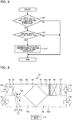
- Fig. 4 is a flowchart indicating an example of control by the control unit 31 of the first air-conditioning apparatus 201 according to Embodiment 1. Control as indicated in Fig. 4 is performed during the heating and humidifying operation or the heating operation by the outside-air processing unit 20. First, the control unit 31 acquires an indoor temperature and indoor humidity based on input signals from the temperature and humidity sensor 62 (step S1).
- step S2 the control unit 31 compares the acquired indoor temperature with a threshold temperature set in advance. In the case where the indoor temperature is lower than the threshold temperature, the process proceeds to step S3, and in the case where the indoor temperature is higher than or equal to the threshold temperature, the process proceeds to step S6.
- step S3 the control unit 31 compares the acquired indoor humidity with a predetermined threshold humidity.
- the threshold humidity is set to a lower value than a set humidity that is a target control value for an indoor humidity. For example, in the case where the set humidity is RH50%, the threshold humidity is set to RH40%.
- the process proceeds to step S4, and in the case where the indoor humidity is higher than or equal to the threshold humidity, the process proceeds to step S5.
- step S4 the control unit 31 causes the damper 61 to be set in the opened state. Also the control unit 31 controls an operation of the refrigerant circuit 40 that includes the driving frequency of the compressor 41, to increase a condensing temperature of the refrigerant in the load-side heat exchanger 45.
- step S5 the control unit 31 causes the damper 61 to be set in the closed state. Also, the control unit 31 controls the operation of the refrigerant circuit 40 that includes the driving frequency of the compressor 41, to increase the condensing temperature of the refrigerant in the load-side heat exchanger 45.
- step S6 the control unit 31 compares the acquired indoor humidity with the predetermined threshold humidity. In the case where the indoor humidity is lower than the threshold humidity, the process proceeds to step S7, and in the case where the indoor humidity is higher than or equal to the threshold humidity, the process proceeds to step S8.
- step S7 the control unit 31 causes the damper 61 to be set in the opened state. Also, the control unit 31 controls the operation of the refrigerant circuit 40 that includes the driving frequency of the compressor 41, to reduce the condensing temperature of the refrigerant in the load-side heat exchanger 45.
- step S8 the control unit 31 causes the damper 61 to be set in the closed state. Also, the control unit 31 controls the operation of the refrigerant circuit 40 that includes the driving frequency of the compressor 41, to reduce the condensing temperature of the refrigerant in the load-side heat exchanger 45.
- the operation of the refrigerant circuit 40 is controlled based on the indoor temperature, and the operation of the damper 61 is controlled based on the indoor humidity.
- the refrigerant circuit 40 is controlled such that the condensing temperature of the refrigerant in the load-side heat exchanger 45 is increased (steps S4 and S5). Thereby, the amount of heat that is transferred to air at the load-side heat exchanger 45 is increased, and the temperature of the supply air SA is raised.
- the refrigerant circuit 40 is controlled such that the condensing temperature of the refrigerant in the load-side heat exchanger 45 is reduced (steps S7 and S8). Thereby, the amount of heat that is transferred to the air at the load-side heat exchanger 45 is reduced, and the temperature of the supply air SA is reduced.
- the damper 61 is set in the opened state (steps S4 and S7). Since the threshold humidity is set to a lower value than the set humidity, the indoor humidity is normally higher than or equal to the threshold humidity during normal operation of the outside-air processing unit 20. On the other hand, immediately after the operation of the outside-air processing unit 20 is started, the indoor humidity may be lower than the threshold humidity. The indoor humidity is normally higher than the humidity of outdoor air even when the indoor humidity is lower than the threshold humidity.
- the damper 61 is set in the opened state, part of the return air RA whose humidity is relatively high as compared with the outdoor air is mixed with the outdoor air to become the supply air SA, and the supply air SA has a high humidity.
- the damper 61 is set in the closed state (steps S5 and S8). This prevents an increase in the humidity of the supply air SA due to mixture of the supply air SA and the return air RA.
- the opening degree of the damper 61 may be controlled based on a value ⁇ RH obtained by subtracting the indoor humidity from the threshold humidity.
- the opening degree of the damper 61 is controlled such that the greater the ⁇ RH, the greater the opening degree of the damper 61, and the smaller the ⁇ RH, the smaller the opening degree of the damper 61.
- a specific command to improve an energy saving performance may be transmitted to the control unit 31 from, for example, the outside of the system controller 30 or an operation unit that operates the outside-air processing unit 20.
- the control unit 31 controls the compressor 41 such that the condensing temperature in the load-side heat exchanger 45 is kept constant at a value smaller than a normal value, and also controls the opening degree of the damper 61 based on the value ⁇ RH obtained by subtracting the indoor humidity from the threshold humidity.
- the first air-conditioning apparatus 201 includes: the housing 50 in which the air supply passage 51 and the air exhaust passage 52 are provided, the air supply passage 51 allowing flow of outdoor air to be supplied into the indoor space, the air exhaust passage 52 allowing flow of indoor air to be exhausted to the outside of the indoor space; the total heat exchanger 57 provided in the housing 50 to transfer at least sensible heat between the outdoor air and the indoor air; the load-side heat exchanger 45 provided at the air supply passage 51 and forming part of the refrigerant circuit 40 that circulates refrigerant, the load-side heat exchanger 45 being provided to transfer heat between the outdoor air and the refrigerant; the humidifying device 58 provided to humidify the outdoor air and provided in part of the air supply passage 51 that is located downward of the load-side heat exchanger 45; the communication passage 60 that causes part of the air exhaust passage 52 that is located upstream of the total heat exchanger 57 and part of the air supply passage 51 that is located downstream of the total heat exchanger 57 to communicate with each
- the first air-conditioning apparatus 201 is an example of an air-conditioning apparatus.
- the total heat exchanger 57 is an example of an air-to-air heat exchanger.
- the load-side heat exchanger 45 is an example of an air-to-refrigerant heat exchanger.
- the damper 61 is an example of an opening/closing device.
- the operation of the damper 61 is controlled based on an indoor humidity, and part of indoor air whose humidity is relatively high as compared with that of outdoor air can be made to flow into the air supply passage 51 through the communication passage 60 and to be supplied along with the outdoor air into the indoor space. It is therefore possible to more promptly raise the indoor humidity.
- the refrigerant temperature in the load-side heat exchanger 45 is controlled based on the indoor temperature, and the temperature of air in a region located upstream of the humidifying device 58 can be raised. Therefore, the indoor temperature and the indoor humidity can be more promptly raised.
- the refrigerant temperature in the load-side heat exchanger 45 is controlled based on the indoor temperature. Therefore, the indoor temperature can be prevented from being unnecessarily raised, and wasteful energy consumption can thus be reduced.
- the control unit 31 may perform the control in the following manner: in the case where the indoor temperature is higher than or equal to the threshold temperature, the control unit 31 controls the refrigerant circuit 40 to reduce the refrigerant temperature in the load-side heat exchanger 45; in the case where the indoor temperature is lower than the threshold temperature, the control unit 31 controls the refrigerant circuit 40 to raise the refrigerant temperature in the load-side heat exchanger 45; in the case where the indoor humidity is higher than or equal to the threshold humidity, the control unit 31 causes the damper 61 to be set in the closed state; and in the case where the indoor humidity is lower than the threshold humidity, the control unit 31 causes the damper 61 to be set in the opened state.
- the control unit 31 may control the opening degree of the damper 61 based on the value ⁇ RH obtained by subtracting the indoor humidity from the threshold humidity.
- the greater the ⁇ RH the larger the amount of indoor air that flows through the communication passage 60 and is mixed with the outdoor air
- the smaller the ⁇ RH the smaller the amount of the above indoor air. It is therefore possible to more promptly raise the indoor humidity while reducing the amount of indoor air that is mixed with the outdoor air as much as possible.
- the control unit 31 may control the refrigerant circuit 40 such that the refrigerant temperature in the load-side heat exchanger 45 is kept constant, and control the opening degree of damper 61 based on the value ⁇ RH obtained by subtracting the indoor humidity from the threshold humidity.
- the control of keeping the condensing temperature at the refrigerant circuit 40 constant is effective, the amount of indoor air to be mixed with the outdoor air is controlled based on the ⁇ RH, and the indoor humidity can thus be more promptly raised.
- the air-conditioning system according to Embodiment 2 also includes the first air-conditioning apparatus 201 provided with the outside-air processing unit 20 and the outdoor unit 21, the second air-conditioning apparatus 202 provided with at least one indoor unit 10 and the outdoor unit 11, and the system controller 30 that controls the first air-conditioning apparatus 201 and the second air-conditioning apparatus 202.
- a heat load in the indoor space 102 is processed mainly by a plurality of the indoor units 10, and an outside-air load is processed mainly by the outside-air processing unit 20.
- the second air-conditioning apparatus 202 includes a refrigerant circuit that circulates refrigerant and that is separate from the refrigerant circuit 40 of the first air-conditioning apparatus 201. At least the heat-source-side heat exchanger of the refrigerant circuit is housed in the outdoor unit 21, and at least the load-side heat exchanger of the refrigerant circuit is housed in the indoor unit 10.
- the second air-conditioning apparatus 202 is capable of performing the cooling operation in which the load-side heat exchanger operates as an evaporator, and the heating operation in which the load-side heat exchanger operates as a condenser.
- Fig. 5 is a flowchart illustrating an example of control by the system controller 30 of the air-conditioning system according to Embodiment 2.
- the system controller 30 determines whether the outside-air processing unit 20 of the first air-conditioning apparatus 201 is performing the heating and humidifying operation or not. In the case where the outside-air processing unit 20 is performing the heating and humidifying operation, the process proceeds to step S12, and in the case where the outside-air processing unit is not performing the heating and humidity operation, the process is ended.
- step S12 the system controller 30 determines whether the indoor unit 10 of the second air-conditioning apparatus 202 is performing the cooling operation or not. In the case where the indoor unit 10 is performing the cooling operation, the process proceeds to step S13, and in the case where the indoor unit 10 is not performing the cooling operation, the process is ended.
- step S13 the system controller 30 controls the second air-conditioning apparatus 202 to raise an evaporating temperature of the refrigerant circuit of the second air-conditioning apparatus 202.
- the air-conditioning system includes the first air-conditioning apparatus 201 that processes an outside-air load, and supplies outdoor air into the indoor space, the second air-conditioning apparatus 202 that processes a load in the indoor space, and the system controller 30 that controls the first air-conditioning apparatus 201 and the second air-conditioning apparatus 202.
- the first air-conditioning apparatus 201 is capable of performing the heating and humidifying operation in which the load-side heat exchanger 45 operates as a condenser and the humidifying device 58 performs humidification.
- the second air-conditioning apparatus 202 includes a load-side heat exchanger that forms part of a refrigerant circuit that circulates refrigerant.
- the second air-conditioning apparatus 202 is capable of performing a cooling operation in which the load-side heat exchanger operates as an evaporator.
- the system controller 30 raises an evaporating temperature of the refrigerant circuit of the second air-conditioning apparatus 202, in the case where the outside-air processing unit 20 of the first air-conditioning apparatus 201 is performing the heating and humidifying operation, and the indoor unit 10 of the second air-conditioning apparatus 202 is performing the cooling operation.
- Fig. 6 is a schematic diagram illustrating a configuration of the outside-air processing unit 20 of the first air-conditioning apparatus 201 according to Embodiment 3.
- a sensible heat exchanger 63 is provided in the housing 50 of the outside-air processing unit 20 to transfer sensible heat between outdoor air that flows through the air supply passage 51 and indoor air that flows through the air exhaust passage 52. That is, unlike the outside-air processing unit 20 of Embodiment 1, the outside-air processing unit 20 of Embodiment 3 includes the sensible heat exchanger 63, instead of the total heat exchanger 57.
- the load-side heat exchanger 45 is provided in part of the upstream-side air supply passage 51a that is located downstream of the air supply fan 47.
- the humidifying device 58 is provided at part of the upstream-side air supply passage 51a that is located downstream of the load-side heat exchanger 45.
- the other configuration of the outside-air processing unit 20 is the same as that of the outside-air processing unit 20 of Embodiment 1. Furthermore, the operations of the damper 61 and other elements of the outside-air processing unit 20 are the same as those in Embodiment 1.
- the load-side heat exchanger 45 and the humidifying device 58 are provided in part of the air supply passage 51 that is located upstream of the sensible heat exchanger 63.
- the load-side heat exchanger 45 is an example of an air-to-refrigerant heat exchanger.
- the sensible heat exchanger 63 is an example of an air-to-air heat exchanger.
Landscapes
- Engineering & Computer Science (AREA)
- Chemical & Material Sciences (AREA)
- Combustion & Propulsion (AREA)
- Mechanical Engineering (AREA)
- General Engineering & Computer Science (AREA)
- Physics & Mathematics (AREA)
- Thermal Sciences (AREA)
- Air Conditioning Control Device (AREA)
- Central Air Conditioning (AREA)
- Ventilation (AREA)
Applications Claiming Priority (1)
| Application Number | Priority Date | Filing Date | Title |
|---|---|---|---|
| PCT/JP2017/024600 WO2019008694A1 (fr) | 2017-07-05 | 2017-07-05 | Climatiseur et système de climatisation |
Publications (3)
| Publication Number | Publication Date |
|---|---|
| EP3650772A1 true EP3650772A1 (fr) | 2020-05-13 |
| EP3650772A4 EP3650772A4 (fr) | 2020-06-03 |
| EP3650772B1 EP3650772B1 (fr) | 2021-08-25 |
Family
ID=64950671
Family Applications (1)
| Application Number | Title | Priority Date | Filing Date |
|---|---|---|---|
| EP17917165.7A Active EP3650772B1 (fr) | 2017-07-05 | 2017-07-05 | Climatiseur et système de climatisation |
Country Status (5)
| Country | Link |
|---|---|
| US (1) | US11293655B2 (fr) |
| EP (1) | EP3650772B1 (fr) |
| JP (1) | JP6800333B2 (fr) |
| CN (1) | CN110799793B (fr) |
| WO (1) | WO2019008694A1 (fr) |
Cited By (2)
| Publication number | Priority date | Publication date | Assignee | Title |
|---|---|---|---|---|
| CN114087743A (zh) * | 2021-11-24 | 2022-02-25 | 美的集团武汉制冷设备有限公司 | 热管新风机及其控制方法、计算机可读存储介质 |
| EP4151915A4 (fr) * | 2020-05-12 | 2023-06-21 | Mitsubishi Electric Corporation | Dispositif de commande de chauffage et programme de commande de chauffage |
Families Citing this family (16)
| Publication number | Priority date | Publication date | Assignee | Title |
|---|---|---|---|---|
| KR102777315B1 (ko) * | 2019-03-04 | 2025-03-10 | 엘지전자 주식회사 | 공기조화기의 실내기 및 그 제어방법 |
| JP6835141B2 (ja) * | 2019-05-31 | 2021-02-24 | ダイキン工業株式会社 | 空調システム |
| JP7477739B2 (ja) * | 2019-06-26 | 2024-05-02 | ダイキン工業株式会社 | 外気処理装置及び空調システム |
| WO2021112085A1 (fr) * | 2019-12-05 | 2021-06-10 | パナソニックIpマネジメント株式会社 | Appareil de ventilation de type à échange de chaleur doté d'une fonction d'humidification |
| CN111829081A (zh) * | 2020-08-10 | 2020-10-27 | 古德沃特空气系统科技(江苏)有限公司 | 一种智能恒氧恒净恒湿新风机 |
| EP4191149B1 (fr) | 2020-12-08 | 2026-01-28 | Samsung Electronics Co., Ltd. | Dispositif de ventilation et système de climatisation intégré le comprenant |
| WO2022124684A1 (fr) * | 2020-12-08 | 2022-06-16 | 삼성전자주식회사 | Dispositif de ventilation et système de climatisation intégré le comprenant |
| US11506417B2 (en) | 2020-12-31 | 2022-11-22 | Trane International Inc. | Dampers placed on the half face of the inlet and the outlet of side-by-side airflow energy recovery sections used as recirculation path |
| CN114110883B (zh) * | 2021-11-24 | 2023-04-25 | 广东美的制冷设备有限公司 | 新风机及其控制方法、计算机可读存储介质 |
| KR20230105434A (ko) * | 2022-01-04 | 2023-07-11 | 삼성전자주식회사 | 환기 시스템 및 그 제어 방법 |
| CN117916536A (zh) | 2022-01-04 | 2024-04-19 | 三星电子株式会社 | 换气系统及其控制方法 |
| US12196442B2 (en) * | 2022-03-28 | 2025-01-14 | Therma-Stor LLC | Dedicated outdoor air system with a plurality of modes of operation |
| JP7833635B2 (ja) * | 2022-07-28 | 2026-03-23 | パナソニックIpマネジメント株式会社 | 除湿機能付き熱交換形換気装置 |
| JP7594206B1 (ja) * | 2023-06-20 | 2024-12-04 | ダイキン工業株式会社 | 空気調和システム |
| WO2025069237A1 (fr) * | 2023-09-27 | 2025-04-03 | 三菱電機株式会社 | Système de climatisation de ventilation |
| US20250362052A1 (en) * | 2024-05-22 | 2025-11-27 | Copeland Lp | Climate-Control System With Sensible and Latent Cooling |
Family Cites Families (25)
| Publication number | Priority date | Publication date | Assignee | Title |
|---|---|---|---|---|
| JPS531956U (fr) * | 1977-01-06 | 1978-01-10 | ||
| JPH0733918B2 (ja) * | 1989-06-16 | 1995-04-12 | 三菱電機株式会社 | 外気処理装置 |
| JPH0686941B2 (ja) * | 1990-05-02 | 1994-11-02 | 木村工機株式会社 | 全外気室内両兼用型空調機 |
| US6131653A (en) * | 1996-03-08 | 2000-10-17 | Larsson; Donald E. | Method and apparatus for dehumidifying and conditioning air |
| JP4656357B2 (ja) | 2001-01-12 | 2011-03-23 | ダイキン工業株式会社 | 空気調和装置 |
| JP4844821B2 (ja) * | 2006-04-06 | 2011-12-28 | 三機工業株式会社 | 空調システム及び空調システムの加湿能力増強方法 |
| JP2009287861A (ja) * | 2008-05-30 | 2009-12-10 | Panasonic Corp | 加湿換気装置 |
| CN101694314B (zh) * | 2009-10-23 | 2012-07-25 | 清华大学 | 一种带自然供热和湿度控制的空气处理装置 |
| CN101995062A (zh) * | 2010-11-09 | 2011-03-30 | 帝思迈环境设备(上海)有限公司 | 一种全热回收的调湿新风热泵 |
| CN201858726U (zh) * | 2010-11-09 | 2011-06-08 | 帝思迈环境设备(上海)有限公司 | 一种全热回收的调湿新风热泵 |
| JP6006593B2 (ja) * | 2012-09-19 | 2016-10-12 | アズビル株式会社 | 空調制御システムおよび空調制御方法 |
| JP2014126208A (ja) * | 2012-12-25 | 2014-07-07 | Ohbayashi Corp | 空調方法および空調システム |
| JP2015021720A (ja) * | 2013-07-24 | 2015-02-02 | 三菱電機株式会社 | 熱交換換気装置 |
| JP6270997B2 (ja) * | 2014-05-14 | 2018-01-31 | 三菱電機株式会社 | 外気処理機及び空気調和機 |
| JP6188939B2 (ja) * | 2014-06-16 | 2017-08-30 | 三菱電機株式会社 | 空気調和システム |
| JP6300921B2 (ja) * | 2014-07-04 | 2018-03-28 | 三菱電機株式会社 | 空調換気装置 |
| JP6234575B2 (ja) * | 2014-07-04 | 2017-11-22 | 三菱電機株式会社 | 換気装置 |
| CN104728977A (zh) * | 2015-03-26 | 2015-06-24 | 北京格瑞力德空调科技有限公司 | 自带全部冷和热源并同时制备冷或热媒的全空气空调机组 |
| CN107923637B (zh) * | 2015-08-20 | 2019-12-17 | 三菱电机株式会社 | 空调系统 |
| US10962254B2 (en) | 2015-08-31 | 2021-03-30 | Mitsubishi Electric Corporation | Ventilation device |
| CN105352066B (zh) * | 2015-09-30 | 2018-04-20 | 中机中联工程有限公司 | 一种适用于温湿度独立控制系统的热回收新风机组及其控制方法 |
| CN205717624U (zh) * | 2016-04-29 | 2016-11-23 | 李国胜 | 适于调湿机组的氟路系统 |
| CN105953352B (zh) * | 2016-05-18 | 2020-05-08 | 青岛海信日立空调系统有限公司 | 一种全热交换器、控制装置、控制方法及空调系统 |
| US11262092B2 (en) * | 2016-06-08 | 2022-03-01 | Mitsubishi Electric Corporation | Air conditioning system including a ventilator that supplies humidified outdoor air |
| CN106288054A (zh) * | 2016-11-02 | 2017-01-04 | 无锡同方人工环境有限公司 | 被动房用空调机组除湿安全运行装置 |
-
2017
- 2017-07-05 CN CN201780092461.8A patent/CN110799793B/zh not_active Expired - Fee Related
- 2017-07-05 WO PCT/JP2017/024600 patent/WO2019008694A1/fr not_active Ceased
- 2017-07-05 EP EP17917165.7A patent/EP3650772B1/fr active Active
- 2017-07-05 JP JP2019528255A patent/JP6800333B2/ja not_active Expired - Fee Related
- 2017-07-05 US US16/500,682 patent/US11293655B2/en active Active
Cited By (3)
| Publication number | Priority date | Publication date | Assignee | Title |
|---|---|---|---|---|
| EP4151915A4 (fr) * | 2020-05-12 | 2023-06-21 | Mitsubishi Electric Corporation | Dispositif de commande de chauffage et programme de commande de chauffage |
| CN114087743A (zh) * | 2021-11-24 | 2022-02-25 | 美的集团武汉制冷设备有限公司 | 热管新风机及其控制方法、计算机可读存储介质 |
| CN114087743B (zh) * | 2021-11-24 | 2024-01-23 | 美的集团武汉制冷设备有限公司 | 热管新风机及其控制方法、计算机可读存储介质 |
Also Published As
| Publication number | Publication date |
|---|---|
| WO2019008694A1 (fr) | 2019-01-10 |
| CN110799793B (zh) | 2021-06-08 |
| US11293655B2 (en) | 2022-04-05 |
| JPWO2019008694A1 (ja) | 2020-05-21 |
| CN110799793A (zh) | 2020-02-14 |
| JP6800333B2 (ja) | 2020-12-16 |
| EP3650772B1 (fr) | 2021-08-25 |
| EP3650772A4 (fr) | 2020-06-03 |
| US20200200413A1 (en) | 2020-06-25 |
Similar Documents
| Publication | Publication Date | Title |
|---|---|---|
| EP3650772B1 (fr) | Climatiseur et système de climatisation | |
| US11262092B2 (en) | Air conditioning system including a ventilator that supplies humidified outdoor air | |
| CN101126530B (zh) | 空调机 | |
| CN110671744B (zh) | 一种空调器及其恒温除湿的控制方法 | |
| EP3396264B1 (fr) | Climatiseur à pompe à chaleur à source d'air | |
| US12480680B2 (en) | Outside air treatment device and air conditioning system | |
| US20200378645A1 (en) | Heat exchange ventilation system | |
| CN113892009B (zh) | 空调系统 | |
| WO2020053929A1 (fr) | Dispositif de climatisation | |
| CN112178778A (zh) | 一种空调辐射末端及多房屋空间辐射末端防结露方法 | |
| JP7374633B2 (ja) | 空気調和機及び空気調和システム | |
| EP3943825A1 (fr) | Système de climatisation | |
| US12595925B2 (en) | Air conditioning system | |
| JPH03164647A (ja) | 空気調和機 | |
| CN113432214A (zh) | 空气调节系统、机房空气调节系统及空气调节控制方法 | |
| US10969145B2 (en) | Method and apparatus for hybrid dehumidification | |
| CN113266883A (zh) | 新风除湿装置 | |
| CN114151940A (zh) | 空调器及其控制方法、控制装置和可读存储介质 | |
| JP3528962B2 (ja) | ヒートポンプ式空調機 | |
| JP2008286444A (ja) | 空気調和装置 | |
| CN112178779A (zh) | 一种辐射末端防结露的空调系统 | |
| KR20240119685A (ko) | 공조 시스템 및 그 제어 방법 | |
| KR20240119684A (ko) | 고효율 공조 시스템 및 그 제어 방법 | |
| CN117091268A (zh) | 恒温恒湿空调及其控制方法 | |
| CN118031374A (zh) | 环境调节设备的控制方法、环境调节设备以及存储介质 |
Legal Events
| Date | Code | Title | Description |
|---|---|---|---|
| STAA | Information on the status of an ep patent application or granted ep patent |
Free format text: STATUS: THE INTERNATIONAL PUBLICATION HAS BEEN MADE |
|
| PUAI | Public reference made under article 153(3) epc to a published international application that has entered the european phase |
Free format text: ORIGINAL CODE: 0009012 |
|
| STAA | Information on the status of an ep patent application or granted ep patent |
Free format text: STATUS: REQUEST FOR EXAMINATION WAS MADE |
|
| 17P | Request for examination filed |
Effective date: 20191209 |
|
| AK | Designated contracting states |
Kind code of ref document: A1 Designated state(s): AL AT BE BG CH CY CZ DE DK EE ES FI FR GB GR HR HU IE IS IT LI LT LU LV MC MK MT NL NO PL PT RO RS SE SI SK SM TR |
|
| AX | Request for extension of the european patent |
Extension state: BA ME |
|
| A4 | Supplementary search report drawn up and despatched |
Effective date: 20200504 |
|
| RIC1 | Information provided on ipc code assigned before grant |
Ipc: F24F 3/14 20060101ALI20200424BHEP Ipc: F24F 7/007 20060101ALI20200424BHEP Ipc: F24F 11/30 20180101AFI20200424BHEP Ipc: F24F 7/08 20060101ALI20200424BHEP Ipc: F24F 5/00 20060101ALI20200424BHEP |
|
| DAV | Request for validation of the european patent (deleted) | ||
| DAX | Request for extension of the european patent (deleted) | ||
| RIC1 | Information provided on ipc code assigned before grant |
Ipc: F24F 11/30 20180101AFI20201218BHEP Ipc: F24F 3/14 20060101ALI20201218BHEP Ipc: F24F 7/007 20060101ALI20201218BHEP Ipc: F24F 11/79 20180101ALI20201218BHEP Ipc: F24F 11/00 20180101ALI20201218BHEP Ipc: F24F 11/86 20180101ALI20201218BHEP Ipc: F24F 3/044 20060101ALI20201218BHEP Ipc: F24F 5/00 20060101ALI20201218BHEP Ipc: F24F 12/00 20060101ALI20201218BHEP Ipc: F24F 7/08 20060101ALI20201218BHEP Ipc: F24F 110/10 20180101ALI20201218BHEP Ipc: F24F 110/20 20180101ALI20201218BHEP |
|
| GRAP | Despatch of communication of intention to grant a patent |
Free format text: ORIGINAL CODE: EPIDOSNIGR1 |
|
| STAA | Information on the status of an ep patent application or granted ep patent |
Free format text: STATUS: GRANT OF PATENT IS INTENDED |
|
| INTG | Intention to grant announced |
Effective date: 20210212 |
|
| GRAS | Grant fee paid |
Free format text: ORIGINAL CODE: EPIDOSNIGR3 |
|
| GRAA | (expected) grant |
Free format text: ORIGINAL CODE: 0009210 |
|
| STAA | Information on the status of an ep patent application or granted ep patent |
Free format text: STATUS: THE PATENT HAS BEEN GRANTED |
|
| AK | Designated contracting states |
Kind code of ref document: B1 Designated state(s): AL AT BE BG CH CY CZ DE DK EE ES FI FR GB GR HR HU IE IS IT LI LT LU LV MC MK MT NL NO PL PT RO RS SE SI SK SM TR |
|
| REG | Reference to a national code |
Ref country code: CH Ref legal event code: EP |
|
| REG | Reference to a national code |
Ref country code: IE Ref legal event code: FG4D Ref country code: AT Ref legal event code: REF Ref document number: 1424188 Country of ref document: AT Kind code of ref document: T Effective date: 20210915 |
|
| REG | Reference to a national code |
Ref country code: DE Ref legal event code: R096 Ref document number: 602017044974 Country of ref document: DE |
|
| REG | Reference to a national code |
Ref country code: LT Ref legal event code: MG9D |
|
| REG | Reference to a national code |
Ref country code: NL Ref legal event code: MP Effective date: 20210825 |
|
| REG | Reference to a national code |
Ref country code: AT Ref legal event code: MK05 Ref document number: 1424188 Country of ref document: AT Kind code of ref document: T Effective date: 20210825 |
|
| PG25 | Lapsed in a contracting state [announced via postgrant information from national office to epo] |
Ref country code: LT Free format text: LAPSE BECAUSE OF FAILURE TO SUBMIT A TRANSLATION OF THE DESCRIPTION OR TO PAY THE FEE WITHIN THE PRESCRIBED TIME-LIMIT Effective date: 20210825 Ref country code: AT Free format text: LAPSE BECAUSE OF FAILURE TO SUBMIT A TRANSLATION OF THE DESCRIPTION OR TO PAY THE FEE WITHIN THE PRESCRIBED TIME-LIMIT Effective date: 20210825 Ref country code: BG Free format text: LAPSE BECAUSE OF FAILURE TO SUBMIT A TRANSLATION OF THE DESCRIPTION OR TO PAY THE FEE WITHIN THE PRESCRIBED TIME-LIMIT Effective date: 20211125 Ref country code: NO Free format text: LAPSE BECAUSE OF FAILURE TO SUBMIT A TRANSLATION OF THE DESCRIPTION OR TO PAY THE FEE WITHIN THE PRESCRIBED TIME-LIMIT Effective date: 20211125 Ref country code: PT Free format text: LAPSE BECAUSE OF FAILURE TO SUBMIT A TRANSLATION OF THE DESCRIPTION OR TO PAY THE FEE WITHIN THE PRESCRIBED TIME-LIMIT Effective date: 20211227 Ref country code: SE Free format text: LAPSE BECAUSE OF FAILURE TO SUBMIT A TRANSLATION OF THE DESCRIPTION OR TO PAY THE FEE WITHIN THE PRESCRIBED TIME-LIMIT Effective date: 20210825 Ref country code: RS Free format text: LAPSE BECAUSE OF FAILURE TO SUBMIT A TRANSLATION OF THE DESCRIPTION OR TO PAY THE FEE WITHIN THE PRESCRIBED TIME-LIMIT Effective date: 20210825 Ref country code: HR Free format text: LAPSE BECAUSE OF FAILURE TO SUBMIT A TRANSLATION OF THE DESCRIPTION OR TO PAY THE FEE WITHIN THE PRESCRIBED TIME-LIMIT Effective date: 20210825 Ref country code: FI Free format text: LAPSE BECAUSE OF FAILURE TO SUBMIT A TRANSLATION OF THE DESCRIPTION OR TO PAY THE FEE WITHIN THE PRESCRIBED TIME-LIMIT Effective date: 20210825 Ref country code: ES Free format text: LAPSE BECAUSE OF FAILURE TO SUBMIT A TRANSLATION OF THE DESCRIPTION OR TO PAY THE FEE WITHIN THE PRESCRIBED TIME-LIMIT Effective date: 20210825 |
|
| PG25 | Lapsed in a contracting state [announced via postgrant information from national office to epo] |
Ref country code: PL Free format text: LAPSE BECAUSE OF FAILURE TO SUBMIT A TRANSLATION OF THE DESCRIPTION OR TO PAY THE FEE WITHIN THE PRESCRIBED TIME-LIMIT Effective date: 20210825 Ref country code: LV Free format text: LAPSE BECAUSE OF FAILURE TO SUBMIT A TRANSLATION OF THE DESCRIPTION OR TO PAY THE FEE WITHIN THE PRESCRIBED TIME-LIMIT Effective date: 20210825 Ref country code: GR Free format text: LAPSE BECAUSE OF FAILURE TO SUBMIT A TRANSLATION OF THE DESCRIPTION OR TO PAY THE FEE WITHIN THE PRESCRIBED TIME-LIMIT Effective date: 20211126 |
|
| PG25 | Lapsed in a contracting state [announced via postgrant information from national office to epo] |
Ref country code: NL Free format text: LAPSE BECAUSE OF FAILURE TO SUBMIT A TRANSLATION OF THE DESCRIPTION OR TO PAY THE FEE WITHIN THE PRESCRIBED TIME-LIMIT Effective date: 20210825 |
|
| PG25 | Lapsed in a contracting state [announced via postgrant information from national office to epo] |
Ref country code: DK Free format text: LAPSE BECAUSE OF FAILURE TO SUBMIT A TRANSLATION OF THE DESCRIPTION OR TO PAY THE FEE WITHIN THE PRESCRIBED TIME-LIMIT Effective date: 20210825 |
|
| REG | Reference to a national code |
Ref country code: DE Ref legal event code: R097 Ref document number: 602017044974 Country of ref document: DE |
|
| PG25 | Lapsed in a contracting state [announced via postgrant information from national office to epo] |
Ref country code: SM Free format text: LAPSE BECAUSE OF FAILURE TO SUBMIT A TRANSLATION OF THE DESCRIPTION OR TO PAY THE FEE WITHIN THE PRESCRIBED TIME-LIMIT Effective date: 20210825 Ref country code: SK Free format text: LAPSE BECAUSE OF FAILURE TO SUBMIT A TRANSLATION OF THE DESCRIPTION OR TO PAY THE FEE WITHIN THE PRESCRIBED TIME-LIMIT Effective date: 20210825 Ref country code: RO Free format text: LAPSE BECAUSE OF FAILURE TO SUBMIT A TRANSLATION OF THE DESCRIPTION OR TO PAY THE FEE WITHIN THE PRESCRIBED TIME-LIMIT Effective date: 20210825 Ref country code: EE Free format text: LAPSE BECAUSE OF FAILURE TO SUBMIT A TRANSLATION OF THE DESCRIPTION OR TO PAY THE FEE WITHIN THE PRESCRIBED TIME-LIMIT Effective date: 20210825 Ref country code: CZ Free format text: LAPSE BECAUSE OF FAILURE TO SUBMIT A TRANSLATION OF THE DESCRIPTION OR TO PAY THE FEE WITHIN THE PRESCRIBED TIME-LIMIT Effective date: 20210825 Ref country code: AL Free format text: LAPSE BECAUSE OF FAILURE TO SUBMIT A TRANSLATION OF THE DESCRIPTION OR TO PAY THE FEE WITHIN THE PRESCRIBED TIME-LIMIT Effective date: 20210825 |
|
| PLBE | No opposition filed within time limit |
Free format text: ORIGINAL CODE: 0009261 |
|
| STAA | Information on the status of an ep patent application or granted ep patent |
Free format text: STATUS: NO OPPOSITION FILED WITHIN TIME LIMIT |
|
| PG25 | Lapsed in a contracting state [announced via postgrant information from national office to epo] |
Ref country code: IT Free format text: LAPSE BECAUSE OF FAILURE TO SUBMIT A TRANSLATION OF THE DESCRIPTION OR TO PAY THE FEE WITHIN THE PRESCRIBED TIME-LIMIT Effective date: 20210825 |
|
| 26N | No opposition filed |
Effective date: 20220527 |
|
| PG25 | Lapsed in a contracting state [announced via postgrant information from national office to epo] |
Ref country code: SI Free format text: LAPSE BECAUSE OF FAILURE TO SUBMIT A TRANSLATION OF THE DESCRIPTION OR TO PAY THE FEE WITHIN THE PRESCRIBED TIME-LIMIT Effective date: 20210825 |
|
| PG25 | Lapsed in a contracting state [announced via postgrant information from national office to epo] |
Ref country code: MC Free format text: LAPSE BECAUSE OF FAILURE TO SUBMIT A TRANSLATION OF THE DESCRIPTION OR TO PAY THE FEE WITHIN THE PRESCRIBED TIME-LIMIT Effective date: 20210825 |
|
| REG | Reference to a national code |
Ref country code: CH Ref legal event code: PL |
|
| REG | Reference to a national code |
Ref country code: BE Ref legal event code: MM Effective date: 20220731 |
|
| PG25 | Lapsed in a contracting state [announced via postgrant information from national office to epo] |
Ref country code: LU Free format text: LAPSE BECAUSE OF NON-PAYMENT OF DUE FEES Effective date: 20220705 Ref country code: LI Free format text: LAPSE BECAUSE OF NON-PAYMENT OF DUE FEES Effective date: 20220731 Ref country code: CH Free format text: LAPSE BECAUSE OF NON-PAYMENT OF DUE FEES Effective date: 20220731 |
|
| PG25 | Lapsed in a contracting state [announced via postgrant information from national office to epo] |
Ref country code: BE Free format text: LAPSE BECAUSE OF NON-PAYMENT OF DUE FEES Effective date: 20220731 |
|
| P01 | Opt-out of the competence of the unified patent court (upc) registered |
Effective date: 20230512 |
|
| PG25 | Lapsed in a contracting state [announced via postgrant information from national office to epo] |
Ref country code: IE Free format text: LAPSE BECAUSE OF NON-PAYMENT OF DUE FEES Effective date: 20220705 |
|
| PGFP | Annual fee paid to national office [announced via postgrant information from national office to epo] |
Ref country code: FR Payment date: 20230608 Year of fee payment: 7 |
|
| PGFP | Annual fee paid to national office [announced via postgrant information from national office to epo] |
Ref country code: GB Payment date: 20230601 Year of fee payment: 7 |
|
| PGFP | Annual fee paid to national office [announced via postgrant information from national office to epo] |
Ref country code: DE Payment date: 20230531 Year of fee payment: 7 |
|
| REG | Reference to a national code |
Ref country code: DE Ref legal event code: R084 Ref document number: 602017044974 Country of ref document: DE |
|
| PG25 | Lapsed in a contracting state [announced via postgrant information from national office to epo] |
Ref country code: MK Free format text: LAPSE BECAUSE OF FAILURE TO SUBMIT A TRANSLATION OF THE DESCRIPTION OR TO PAY THE FEE WITHIN THE PRESCRIBED TIME-LIMIT Effective date: 20210825 Ref country code: CY Free format text: LAPSE BECAUSE OF FAILURE TO SUBMIT A TRANSLATION OF THE DESCRIPTION OR TO PAY THE FEE WITHIN THE PRESCRIBED TIME-LIMIT Effective date: 20210825 |
|
| PG25 | Lapsed in a contracting state [announced via postgrant information from national office to epo] |
Ref country code: HU Free format text: LAPSE BECAUSE OF FAILURE TO SUBMIT A TRANSLATION OF THE DESCRIPTION OR TO PAY THE FEE WITHIN THE PRESCRIBED TIME-LIMIT; INVALID AB INITIO Effective date: 20170705 |
|
| REG | Reference to a national code |
Ref country code: GB Ref legal event code: 746 Effective date: 20240603 |
|
| PG25 | Lapsed in a contracting state [announced via postgrant information from national office to epo] |
Ref country code: MT Free format text: LAPSE BECAUSE OF FAILURE TO SUBMIT A TRANSLATION OF THE DESCRIPTION OR TO PAY THE FEE WITHIN THE PRESCRIBED TIME-LIMIT Effective date: 20210825 |
|
| REG | Reference to a national code |
Ref country code: DE Ref legal event code: R119 Ref document number: 602017044974 Country of ref document: DE |
|
| GBPC | Gb: european patent ceased through non-payment of renewal fee |
Effective date: 20240705 |
|
| PG25 | Lapsed in a contracting state [announced via postgrant information from national office to epo] |
Ref country code: DE Free format text: LAPSE BECAUSE OF NON-PAYMENT OF DUE FEES Effective date: 20250201 |
|
| PG25 | Lapsed in a contracting state [announced via postgrant information from national office to epo] |
Ref country code: FR Free format text: LAPSE BECAUSE OF NON-PAYMENT OF DUE FEES Effective date: 20240731 |
|
| PG25 | Lapsed in a contracting state [announced via postgrant information from national office to epo] |
Ref country code: GB Free format text: LAPSE BECAUSE OF NON-PAYMENT OF DUE FEES Effective date: 20240705 |
|
| PG25 | Lapsed in a contracting state [announced via postgrant information from national office to epo] |
Ref country code: TR Free format text: LAPSE BECAUSE OF FAILURE TO SUBMIT A TRANSLATION OF THE DESCRIPTION OR TO PAY THE FEE WITHIN THE PRESCRIBED TIME-LIMIT Effective date: 20210825 |