EP3650780B1 - Robot culinaire - Google Patents
Robot culinaire Download PDFInfo
- Publication number
- EP3650780B1 EP3650780B1 EP18206311.5A EP18206311A EP3650780B1 EP 3650780 B1 EP3650780 B1 EP 3650780B1 EP 18206311 A EP18206311 A EP 18206311A EP 3650780 B1 EP3650780 B1 EP 3650780B1
- Authority
- EP
- European Patent Office
- Prior art keywords
- container
- cold energy
- heat
- space
- food
- Prior art date
- Legal status (The legal status is an assumption and is not a legal conclusion. Google has not performed a legal analysis and makes no representation as to the accuracy of the status listed.)
- Active
Links
Images




Classifications
-
- A—HUMAN NECESSITIES
- A47—FURNITURE; DOMESTIC ARTICLES OR APPLIANCES; COFFEE MILLS; SPICE MILLS; SUCTION CLEANERS IN GENERAL
- A47J—KITCHEN EQUIPMENT; COFFEE MILLS; SPICE MILLS; APPARATUS FOR MAKING BEVERAGES
- A47J43/00—Implements for preparing or holding food, not provided for in other groups of this subclass
- A47J43/04—Machines for domestic use not covered elsewhere, e.g. for grinding, mixing, stirring, kneading, emulsifying, whipping or beating foodstuffs, e.g. power-driven
- A47J43/07—Parts or details, e.g. mixing tools, whipping tools
- A47J43/0727—Mixing bowls
-
- A—HUMAN NECESSITIES
- A47—FURNITURE; DOMESTIC ARTICLES OR APPLIANCES; COFFEE MILLS; SPICE MILLS; SUCTION CLEANERS IN GENERAL
- A47J—KITCHEN EQUIPMENT; COFFEE MILLS; SPICE MILLS; APPARATUS FOR MAKING BEVERAGES
- A47J41/00—Thermally-insulated vessels, e.g. flasks, jugs, jars
- A47J41/0038—Thermally-insulated vessels, e.g. flasks, jugs, jars comprising additional heating or cooling means, i.e. use of thermal energy in addition to stored material
- A47J41/005—Thermally-insulated vessels, e.g. flasks, jugs, jars comprising additional heating or cooling means, i.e. use of thermal energy in addition to stored material comprising heat or cold producing means, i.e. energy transfer from outside the vessel
-
- A—HUMAN NECESSITIES
- A47—FURNITURE; DOMESTIC ARTICLES OR APPLIANCES; COFFEE MILLS; SPICE MILLS; SUCTION CLEANERS IN GENERAL
- A47J—KITCHEN EQUIPMENT; COFFEE MILLS; SPICE MILLS; APPARATUS FOR MAKING BEVERAGES
- A47J43/00—Implements for preparing or holding food, not provided for in other groups of this subclass
- A47J43/04—Machines for domestic use not covered elsewhere, e.g. for grinding, mixing, stirring, kneading, emulsifying, whipping or beating foodstuffs, e.g. power-driven
- A47J43/07—Parts or details, e.g. mixing tools, whipping tools
- A47J43/0716—Parts or details, e.g. mixing tools, whipping tools for machines with tools driven from the lower side
-
- A—HUMAN NECESSITIES
- A47—FURNITURE; DOMESTIC ARTICLES OR APPLIANCES; COFFEE MILLS; SPICE MILLS; SUCTION CLEANERS IN GENERAL
- A47J—KITCHEN EQUIPMENT; COFFEE MILLS; SPICE MILLS; APPARATUS FOR MAKING BEVERAGES
- A47J43/00—Implements for preparing or holding food, not provided for in other groups of this subclass
- A47J43/04—Machines for domestic use not covered elsewhere, e.g. for grinding, mixing, stirring, kneading, emulsifying, whipping or beating foodstuffs, e.g. power-driven
- A47J43/07—Parts or details, e.g. mixing tools, whipping tools
- A47J43/08—Driving mechanisms
- A47J43/085—Driving mechanisms for machines with tools driven from the lower side
-
- F—MECHANICAL ENGINEERING; LIGHTING; HEATING; WEAPONS; BLASTING
- F25—REFRIGERATION OR COOLING; COMBINED HEATING AND REFRIGERATION SYSTEMS; HEAT PUMP SYSTEMS; MANUFACTURE OR STORAGE OF ICE; LIQUEFACTION SOLIDIFICATION OF GASES
- F25B—REFRIGERATION MACHINES, PLANTS OR SYSTEMS; COMBINED HEATING AND REFRIGERATION SYSTEMS; HEAT PUMP SYSTEMS
- F25B21/00—Machines, plants or systems, using electric or magnetic effects
- F25B21/02—Machines, plants or systems, using electric or magnetic effects using Peltier effect; using Nernst-Ettinghausen effect
-
- F—MECHANICAL ENGINEERING; LIGHTING; HEATING; WEAPONS; BLASTING
- F25—REFRIGERATION OR COOLING; COMBINED HEATING AND REFRIGERATION SYSTEMS; HEAT PUMP SYSTEMS; MANUFACTURE OR STORAGE OF ICE; LIQUEFACTION SOLIDIFICATION OF GASES
- F25D—REFRIGERATORS; COLD ROOMS; ICE-BOXES; COOLING OR FREEZING APPARATUS NOT OTHERWISE PROVIDED FOR
- F25D31/00—Other cooling or freezing apparatus
- F25D31/006—Other cooling or freezing apparatus specially adapted for cooling receptacles, e.g. tanks
-
- H—ELECTRICITY
- H10—SEMICONDUCTOR DEVICES; ELECTRIC SOLID-STATE DEVICES NOT OTHERWISE PROVIDED FOR
- H10N—ELECTRIC SOLID-STATE DEVICES NOT OTHERWISE PROVIDED FOR
- H10N10/00—Thermoelectric devices comprising a junction of dissimilar materials, i.e. devices exhibiting Seebeck or Peltier effects
- H10N10/10—Thermoelectric devices comprising a junction of dissimilar materials, i.e. devices exhibiting Seebeck or Peltier effects operating with only the Peltier or Seebeck effects
- H10N10/13—Thermoelectric devices comprising a junction of dissimilar materials, i.e. devices exhibiting Seebeck or Peltier effects operating with only the Peltier or Seebeck effects characterised by the heat-exchanging means at the junction
-
- H—ELECTRICITY
- H10—SEMICONDUCTOR DEVICES; ELECTRIC SOLID-STATE DEVICES NOT OTHERWISE PROVIDED FOR
- H10N—ELECTRIC SOLID-STATE DEVICES NOT OTHERWISE PROVIDED FOR
- H10N10/00—Thermoelectric devices comprising a junction of dissimilar materials, i.e. devices exhibiting Seebeck or Peltier effects
- H10N10/10—Thermoelectric devices comprising a junction of dissimilar materials, i.e. devices exhibiting Seebeck or Peltier effects operating with only the Peltier or Seebeck effects
- H10N10/17—Thermoelectric devices comprising a junction of dissimilar materials, i.e. devices exhibiting Seebeck or Peltier effects operating with only the Peltier or Seebeck effects characterised by the structure or configuration of the cell or thermocouple forming the device
-
- F—MECHANICAL ENGINEERING; LIGHTING; HEATING; WEAPONS; BLASTING
- F25—REFRIGERATION OR COOLING; COMBINED HEATING AND REFRIGERATION SYSTEMS; HEAT PUMP SYSTEMS; MANUFACTURE OR STORAGE OF ICE; LIQUEFACTION SOLIDIFICATION OF GASES
- F25B—REFRIGERATION MACHINES, PLANTS OR SYSTEMS; COMBINED HEATING AND REFRIGERATION SYSTEMS; HEAT PUMP SYSTEMS
- F25B2321/00—Details of machines, plants or systems, using electric or magnetic effects
- F25B2321/02—Details of machines, plants or systems, using electric or magnetic effects using Peltier effects; using Nernst-Ettinghausen effects
- F25B2321/023—Mounting details thereof
Definitions
- the present invention relates to a food processor, and more particularly, to a food processor for performing tasks such as the grinding, processing, and preparing of food.
- Food processors are normally used by placing food items into their container and processing the food items using a processing member such as a blade or screw.
- Document 1 discloses a heating and cooling cup including a cup body, a stirring device, a heating and cooling chip, and a heat sink module, wherein a heat conductive block is disposed under the cup body, the heat conductive block abuts against the heating and cooling chip, the stirring device has a stirring rod disposed in the cup body, and a bottom surface of the heating and cooling chip abuts against a heat conductive block of the heat sink module.
- Document 2 discloses a fruit chiller having a semispheric al bowl-like container for holding fruit or other food products with the bowl forming with the supporting base a cooling air supply passage, wherein cooling air flows into the bowl over the upper edge and variations in the cross section of the cooling air s upply passage induces a turbulence in the cooling air that enhances air distribution an d cooling efficiency.
- the present invention provides a food processor for keeping food fresh or preparing it.
- the present invention provides a food processor including: a main body; and a container that forms a food-containing space for containing food items and is detachably mounted to the main body, wherein the container comprises a processing member that is rotatably mounted within the food-containing space and processes the food items, wherein the main body comprises a cold generator for transmitting cold energy to the container by coming into contact with at least part of the container and the cold generator forms a refrigeration space for containing part of the container, with the container mounted on the main body, wherein the cold generator comprises a cold energy transfer plate that determines the lateral shape of the refrigeration space and a cold generating unit that surrounds the side of the refrigeration space; and the cold energy transfer plate is ring-shaped, with the inside and outside formed on different planes and the inside being closer to the center of the main body than the outside.
- the container may include a conductive plate for conducting cold energy provided by the cold generator to the food-containing space by coming into contact with the cold energy transfer plate.
- the conductive plate may be detachably mounted to the container.
- the cold generating unit comprises a heat transfer element for generating cold energy.
- the cold generator may include: a heat sink for supporting the heat-transfer element and dissipating heat generated from the heat-transfer element; and a hot air vent port for releasing hot air dissipated by the heat sink.
- the heat-transfer element may include a Peltier element, the Peltier element having a heat-generating surface facing the heat sink and a heat-absorbing surface facing the container.
- the cold energy generating unit may include a plurality of heat-transfer elements arranged to surround the side of the refrigeration space, and the cold generator may further include a heat sink that surrounds the side of the refrigeration space, supports the heat-transfer elements, and dissipates heat generated from the heat-transfer elements.
- the refrigeration space may have a bowl shape in which the cross-sectional area increases towards the container, in order to hold part of the container in the refrigeration space and allow the cold generator to support the container.
- a part of the container held in the refrigeration space may have a wedge shape corresponding to the bowl shape, and the part of the container may be formed with a conductive plate that conducts cold energy transmitted from the cold energy transfer plate to the food-containing space by coming into contact with the cold energy transfer plate, with the container mounted on the main body.
- the main body further includes a motor and a power transmitter for transmitting the torque of the motor to the processing member, and the power transmitter may be connected to the processing member through the refrigeration space.
- the cold generator may further include a container combining space formed below the refrigeration space so as to connect to the refrigeration space, and the power transmitter may be exposed to the container combining space and connected to the processing member through the container combining space.
- the main body may further include a base including a motor and a power transmitter for transmitting the torque of the motor to the processing member, and the cold generator may be provided on the base in such a manner that the end of the power transmitter is externally exposed.
- the cold generating unit comprises a heat transfer element for generating cold energy.
- the cold generator may include: a heat sink for supporting the heat-transfer element and dissipating heat generated from the heat-transfer element; and a hot air vent port for releasing hot air dissipated by the heat sink, wherein the hot air vent port forms a portion of the side of the main body.
- the cold generator may form a container receiving space for receiving the bottom of the container, and the heat-transfer element, the heat sink, and the hot air vent port may be configured to surround the side of the container receiving space, and the end of the power transmitter may be exposed within the container receiving space.
- the food processor may further include a cold energy transfer plate that is located between the heat-transfer element and the container, transmits the cold energy of the heat-transfer element to the container, and allows the container to be seated in place.
- the main body may further include a blower unit that supplies air to the cold generator and allows the air to flow around the container after the air passes through the cold generator and cools down.
- a blower unit that supplies air to the cold generator and allows the air to flow around the container after the air passes through the cold generator and cools down.
- the food processor may further include an enclosure for enclosing the container, wherein the air provided by the blower unit is supplied between the container and the enclosure after the air passes through the cold generator and cools down.
- FIG. 1 is a perspective view of a food processor according to an exemplary embodiment of the present invention.
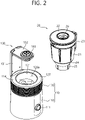
- FIG. 2 is an exploded perspective view of the food processor shown in FIG. 1 .
- FIG. 3 is a longitudinal sectional view of the main body shown in FIG. 2 .
- a food processor 1 includes a main body 10 and a container 20, and the main body 10 includes a base 110 and a cold generator 120.
- the base 110 may internally include a motor 112, a vacuum pump 113, and a circuit board (not shown) for controlling the motor 112 and the vacuum pump 113.
- a motor 112 and/or vacuum pump 113 may be selectively included, the following description will be given of a food processor 1 including both the motor 112 and the vacuum pump 113.
- a manipulating means 111 for manipulating the food processor 1 may be provided on the front and/or side of the base 110.
- this exemplary embodiment illustrates a dial for controlling the output of the motor 112 or vacuum pump 113 as the manipulating means 111, manipulating means such as a capacitive or pressure-sensitive touch display, an electrode switch, etc. may be used.
- the cold generator 120 is provided on the base 110.
- the cold generator 120 is a component where a container 20 mounted onto the main body 10 is seated and secured and which provides cold energy to the container 20.
- the cold generator 120 includes a space 126a and 126b for holding part (a conductive plate 24 and a bottom rim 25) of the container 20 so that part of the container 20 is held in it when the container 20 is mounted on the main body 10.
- part a conductive plate 24 and a bottom rim 25
- the food processor 1 further includes a vacuum supply 130 that supplies vacuum pressure from the vacuum motor 113 to the container 20.
- the vacuum supply 130 includes a supporting post 131, a swing arm 132, and an intake port 133.
- the supporting post 131 may extend upward from one side of the cold generator 120.
- the swing arm 132 is rotatably mounted at the top edge of the supporting post 131, and the intake port 133 is provided on an end of the swing arm 132.
- the intake port 133 is connected to the vacuum pump 113 via a vacuum exhaust line 134.
- the vacuum exhaust line 134 may be placed in such a way as to pass through the insides of the swing arm 132 and supporting post 131. It is preferred that the vacuum exhaust line 134 is made of a highly flexible material so as to deform along the swing arm 132 when the swing arm 132 and the intake port 133 pivoting on the supporting post 131.
- the intake port 133 is securely attached to the lid 22 of the container 20 so that vacuum pressure created by the vacuum pump 113 is transmitted to the food-containing space 27 in a receptacle 21 through the vacuum exhaust line 134, intake port 12, and lid 22.
- the cold generator 120 will be described in details below.
- FIG. 4 is an exploded perspective view of part of the cold generator shown in FIG. 3 .
- FIG. 5 is a longitudinal sectional view of the exploded perspective view of the main body shown in FIG. 2 .
- the cold generator 120 includes a cold energy transfer plate 121, a cold energy generating unit 122, a support frame 123, a heat sink 124, a housing 125, and a top plate 127.
- the cold energy transfer plate 121 is configured to form a bowl-shaped refrigeration space 126a. More specifically, the refrigeration space 126a is formed in such a way that its horizontal cross-sectional area increases towards the container 20, and the bottom of the refrigeration space 126a is open to connect to a container combining space 126b formed below the refrigeration space 126a.
- the cold energy transfer plate 121 is ring-shaped, with the inside and outside formed on different planes and the inside being closer to the center of the main body than the outside. That is, the cold energy transfer plate 121 may be in the shape of a tube that expands towards the container 20.
- the bowl-shaped refrigeration space 126a may improve cold energy transfer efficiency, and at the same time the refrigeration space 126a may support the container 20.
- the cold energy transfer plate 121 is made of a highly thermal conductive material in order to efficiently transfer heat generated by the cold energy generating unit 122 to be described later towards the container 20.
- the cold energy transfer plate 121 is a member that comes into contact with the conductive plate 24 of the container 20, with the container 20 mounted on the main body 10; hence, it is preferable that the cold energy transfer plate 121 is made of a highly wear-resistant material.
- the cold energy transfer plate 121 is made of a highly corrosion-resistant material because frost may form on the surface of the cold energy transfer plate 121 due to the temperature difference between the cold energy transmitted to the cold energy transfer plate 121 and the atmospheric air.
- the cold energy generating unit 122 is a component that generates cold energy, and may consist of a plurality of heat-transfer elements that are supplied with electrical energy from the main body 10 and produce cold energy. While the following description will be given by an example of using Peltier elements as the heat-transfer elements, the present invention is not limited to this example, and other types of heat-transfer elements than the Peltier elements or other components besides the heat-transfer elements may be used as long as they are able to generate cold energy.
- the Peltier elements are elements that use the Peltier effect in which a temperature difference occurs when an electric current flows through two different metals connected to each other. If a direct current voltage is applied to both ends of a Peltier element, heat absorption occurs on one side and heat generation occurs on the other side depending on the direction of the current.
- the cold generator 120 includes a plurality of Peltier elements 122 arranged in an approximately circular pattern.
- Each Peltier element 122 is fitted in such a way that a heat-absorbing surface 122a faces the container 20 and a heat-generating surface 122b faces the heat sink 124.
- the heat-absorbing surface 122a comes into contact with the outer surface of the cold energy transfer plate 121, and the heat-generating surface 122b comes into contact with a heat-transfer element mounting surface 124a of the heat sink 124.
- heat-absorbing surface receiving slots 121a for receiving the heat-absorbing surfaces 122a may be formed on the outer surface of the cold energy transfer plate 121.
- the support frame 123 may be provided between the cold energy transfer plate 121 and the heat sink 124 to support the plurality of Peltier elements 122.
- the support frame 123 may be formed in a bowl shape similar to that of the cold energy transfer plate 121, and heat-transfer element mounting slots 123a for confining the mounting positions of the plurality of Peltier elements 122 and securely supporting the plurality of Peltier elements 122 may be formed to correspond one-to-one to the positions of the Peltier elements 121.
- the heat sink 124 is in contact with the heat-generating surfaces 122b of the Peltier elements 122 and dissipates heat generated from the heat-generating surfaces 122b of the Peltier elements 122.
- the top surface of the heat sink 124 is formed in a bowl shape to support the support frame 123 and the Peltier elements 122, and, as described above, heat-transfer element mounting surfaces 124a where the heat-generating surfaces 122b of the Peltier elements 122 are mounted may be formed on the top surface of the heat sink 124.
- the heat sink 124 may be formed of a highly thermal conductive material so as to efficiently dissipate heat generated from the Peltier elements 122.
- the heat sink 124 too has an overall ring shape to enclose the refrigeration space 126a, with its heat dissipating fins extending downward from the top surface where the heat-transfer element mounting surfaces 124a are formed, thereby improving heat dissipation and at the same time forming a container combining space 126b below the refrigeration space 126a.
- the housing 125 is configured to enclose the heat sink 124, in order to hold and fix the heat sink 124 in place.
- the housing 125 includes a power transmitter recess 125c formed through the bottom surface.
- the power transmitter receiving recess 125c is a component for inserting a power transmitter 114 connected to an output shaft of the motor 112 therethrough.
- the housing 125 may be formed with a dividing wall around the power transmitter receiving recess 125c to define the container combining space 126b.
- the cold energy transfer plate 121 and/or support frame 123 are placed on the dividing wall, and the heat sink 124 is located outside the container combining space 126b with respect to the dividing wall.
- the power transmitter 114 inserted into the housing 125 through the power transmitter receiving recess 125c, may be exposed within the container combining space 126b or refrigeration space 126a of the cold generator 120.
- the housing 125 includes at least one fan block 125b located between the outer surface of the housing 125 and the heat sink 124.
- a hot air vent port 125a is formed on the outer surface of the housing 125, corresponding to the fan block 125b.
- a fan (not shown) for blowing out hot air dissipated by the heat sink 124 may be included in the fan block 125b so as to let out the hot air dissipated by the heat sink 124 to the hot air vent port 125a.
- the outer surface of the housing 125 has a horizontal sectional shape which is the same as or similar to that of the outer surface of the base 110, thereby giving a better sense of unity between the base 110 and the housing 125.
- the top plate 127 is a cover member that extends to the top edge of the cold energy transfer plate 121 from the top edge of the outer surface of the housing 125.
- the top plate 127 may be used as a component for mounting part of the container 20 or supporting part of the container 20.
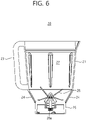
- FIG. 6 is a longitudinal sectional view of part of the container shown in FIG. 2 .
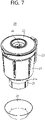
- FIG. 7 is an exploded perspective view of the container shown in FIG. 2 .
- the container 20 may include a receptacle 21, a lid 22, a handle 23, a conductive plate 24, and a bottom rim 25.
- the receptacle 21 forms a food-containing space 27 for containing food items to prepare, and the container 20 includes a processing member 28 that is rotatably mounted within the receptacle 21 and processes the food items.
- the processing member 28 may be a blade or the like for grinding food items.
- a coupling gear 28a for coupling to the processing member 28 is provided below the outside of the receptacle 21.
- the processing member 28 and the coupling gear 28a are connected by a connecting shaft that penetrates the receptacle 21 and is rotatable with respect to the receptacle 21.
- the coupling gear 28a is attached to the power transmitter 114 which is exposed within the refrigeration space 126a and/or container combining space 126b of the cold generator 120, and transmits the torque of the motor 112 to the processing member 28.
- the bottom rim 25 extends downward from the side of the receptacle 21, and is inserted into the container combining space 126b of the cold generator 120 so that the container 20 is mounted on the main body 10.
- the area under the food-containing space 27 where the processing member 28 is provided is shaped in such a way that its horizontal sectional area decreases gradually towards the bottom.
- the side 24a of the lower part of the receptacle 21 is wedge-shaped and extends down to the bottom rim 25.
- An assembly space where the conductive plate 24 can be mounted is formed on the lower part side 24a.
- the conductive plate 24 is detachably mounted to the lower part side 24a so that the user can remove the conductive plate 24 and wash it if required.
- the conductive plate 24 is a component that comes into contact with the cold energy transfer plate 121 of the cold generator 120, with the container 20 mounted on the main body 10, and is preferably made of a highly wear-resistant material. Also, it is preferable that the conductive plate 24 is made of a highly corrosion-resistant material because frost may form on the surface of the conductive plate 24 due to the temperature difference between the cold energy transmitted to the cold energy transfer plate 12 and the air.
- the conductive plate 24 may have a shape complementary to the shape of the cold energy transfer plate 121 so as to be securely attached to the cold energy transfer plate 121.
- the handle 23 is formed on one side of the receptacle 21 to make it easy for the user to remove the container 20 from the main body 10 or move the container 20 to the main body and fit it onto the main body 10.
- the lid 22 is a component for covering the open top of the receptacle 21, and the lid 22 has a sealing member where it comes into contact with the receptacle 21, in order to keep the food-containing space 27 airtight.
- a valve 26 is provided on the lid 22.
- the valve 26 Even if the lid 22 and the intake port 133 are separated from each other by moving the container 20 from the swing arm 132 when the internal pressure of the food-containing space 27 is lower than the atmospheric pressure, the valve 26 still prevents outside air from entering the food-containing space 27 due to the difference between the atmospheric air and the internal pressure of the food-containing space 27. In this instance, if the user wants to separate the receptacle 21 and the lid 22, they may easily separate the receptacle 21 and the lid 22 by pushing or pulling the valve 26, because there is no pressure difference between the inside and outside of the receptacle 21 as outside air enters the food-containing space 27.
- the food processor 1 includes a cold generator 120 to keep processed and/or unprocessed food items fresh in the container 20 as needed by the user.
- the user can cut food items that they will prepare in the morning using the food processor 1, put them in the receptacle 21, place the container 20 on the main body 10, and then run the cold generator 120 to keep the food items fresh during the night.
- the user can simply prepare the food by running the processing member 28. This way, the user can easily prepare and enjoy their meals in the busy morning hours when they are getting ready for office or school.
- the user may keep the leftover food fresh by running the cold generator 120.
- the food processor 1 including the cold generator 120 allows for putting food ingredients and a liquid such as milk in the receptacle 21 and processing them, and even allows for making slush, ice cream, etc. simply by running the cold generator 120.
- a food processor will be described below.
- the same reference numerals are used to denote parts similar to those in the foregoing exemplary embodiment, and descriptions of parts common to this exemplary embodiment and the foregoing exemplary embodiment will be omitted.
- FIG. 8 is a cross-sectional view schematically showing a food processor according to another exemplary embodiment of the present invention.
- the main body 210 of the food processor 2 further includes a blower unit 141, as compared to the food processor 1 according to the foregoing exemplary embodiment.
- the blower unit 141 may be placed between the cold generator 120 and the base 110 and configured to supply air towards the cold generator 120.
- the main body 210 may include a blower unit mounting space 140 for mounting the blower unit 141 between the cold generator 120 and the base 110.
- the ceiling of the blower unit mounting space 140 may correspond to the bottom 126c of the container combining space 126b, and the bottom thereof may correspond to the top surface 115 of the base 110.
- a blower port 142 connecting the blower unit mounting space 140 and the container combining space 126b is provided to direct the flow of air produced by the blower unit 141 from the blower unit mounting space 140 to the container combining space 126b.
- the blower port 142 may be formed through the side of the container combining space 126b, but in some embodiments the blower port 142 may be located elsewhere as long as the blower unit mounting space 140 and the container combining space 126b can be connected together.
- the blower port 142 may be formed through the bottom 126c of the container combining space 126b.
- the air produced by the blower unit 141 and passed through the blower port 142 cools down and turns into cold air as it passes through the cold generator 120. Concretely speaking, the air passed through the blower port 142 turns into cold air as it passes through the refrigeration space 126a and the cold energy transfer plate 121.
- an air inlet (not shown) may be formed on the side or bottom of the blower unit mounting space 140 to draw air into the blower unit mounting space 140.
- the cold air passes through between the container 20 and the cold generator 120, more specifically, between the container 20 and the cold energy transfer plate 121, and flows around the container 20.
- the food processor 2 allows for keeping food fresh in the container 20 in a more efficient way, because the cold generator 120 cools the lower part of the container 20 and at the same time the cold air cools the upper part of the container 20.
- the cold air supplied between the container 20 and the enclosure 30 is maintained between the container 20 and the enclosure 30, thereby improving the cooling efficiency of the cold air in the upper part of the container 20.
- FIG. 8 illustrates an example in which the blower unit 141 is mounted in a dedicated blower unit mounting space 140
- the blower unit 141 may be placed within the base 111.
- the flow of air produced by the blower unit 141 may be directed toward the cold generator 120 via the base 111 and the container combining space 126b.
- Food items contained in the food processor may be kept or prepared fresh.
- Cold food such as ice cream or slush may be made.
Landscapes
- Engineering & Computer Science (AREA)
- Mechanical Engineering (AREA)
- Food Science & Technology (AREA)
- Physics & Mathematics (AREA)
- Thermal Sciences (AREA)
- General Engineering & Computer Science (AREA)
- Chemical & Material Sciences (AREA)
- Combustion & Propulsion (AREA)
- Devices That Are Associated With Refrigeration Equipment (AREA)
Claims (13)
- Robot culinaire (1) comprenant :un corps principal (10) ; etun récipient (20) qui forme un espace contenant des aliments (27) pour contenir des aliments et qui est monté, de manière amovible, sur le corps principal (10),dans lequel le récipient (20) comprend un organe de traitement (28) qui est monté, de manière à pouvoir tourner, à l'intérieur de l'espace contenant des aliments (27) et traite les aliments,dans lequel le corps principal (10) comprend en outre un moteur (112) et un transmetteur de puissance (114) pour transmettre le couple du moteur (112) à l'organe de traitement (28),dans lequel le corps principal (10) comprend un générateur d'énergie froide (120) pour transmettre de l'énergie froide au récipient (20) en venant au contact d'au moins une partie du récipient (20) et le générateur d'énergie froide forme un espace de réfrigération (126a) pour contenir une partie du récipient (20), avec le récipient (20) monté sur le corps principal (10),caractérisé en ce quele générateur d'énergie froide (120) comprend une plaque de transfert d'énergie froide (121) qui détermine la forme latérale de l'espace de réfrigération (126a) et une unité de génération d'énergie froide (122) qui entoure le côté de l'espace de réfrigération (126a) ; etla plaque de transfert d'énergie froide (121) est de forme annulaire, avec l'intérieur et l'extérieur formés sur des plans différents et l'intérieur étant plus proche du centre du corps principal (10) que de l'extérieur.
- Robot culinaire (1) selon la revendication 1, dans lequel le récipient (20) comprend une plaque conductrice (24) pour conduire de l'énergie froide fournie par le générateur d'énergie froide (120) jusqu'à l'espace contenant des aliments (27) en venant au contact de la plaque de transfert d'énergie froide (121).
- Robot culinaire (1) selon la revendication 1, dans lequel l'unité de génération d'énergie froide (122) comprend un élément de transfert de chaleur pour générer de l'énergie froide,
dans lequel le générateur d'énergie froide (120) comprend en outre :un dissipateur de chaleur (124) pour supporter l'élément de transfert de chaleur et dissiper la chaleur générée depuis l'élément de transfert de chaleur ; etun orifice d'évacuation d'air chaud (125a) pour libérer l'air chaud dissipé par le dissipateur de chaleur (124). - Robot culinaire (1) selon la revendication 3, dans lequel l'élément de transfert de chaleur comprend un élément à effet Peltier (122),
l'élément à effet Peltier (122) comportant une surface de génération de chaleur (122b) faisant face au dissipateur de chaleur (124) et une surface d'absorption de chaleur (122a) faisant face au récipient (20). - Robot culinaire (1) selon la revendication 1, dans lequel l'espace de réfrigération (126a) présente une forme de bol dans laquelle une aire en coupe transversale augmente vers le récipient (20), afin de maintenir une partie du récipient (20) dans l'espace de réfrigération (126a) et permettre au générateur d'énergie froide (120) de supporter le récipient (20).
- Robot culinaire (1) selon la revendication 5, dans lequel une partie du récipient (20) maintenue dans l'espace de réfrigération (126a) présente une forme de coin correspondant à la forme de bol, et la partie du récipient (20) est formée avec une plaque conductrice (24) qui conduit l'énergie froide transmise depuis la plaque de transfert d'énergie froide (121) jusqu'à l'espace contenant des aliments (27) en venant au contact de la plaque de transfert d'énergie froide (121), avec le récipient (20) monté sur le corps principal (10).
- Robot culinaire (1) selon la revendication 1, dans lequel le transmetteur de puissance (114) est relié à l'organe de traitement (28) à travers l'espace de réfrigération (126a).
- Robot culinaire selon la revendication 1, dans lequel le générateur d'énergie froide (120) comprend en outre un espace de combinaison de récipient (126b) formé au-dessous de l'espace de réfrigération (126a) de manière à être relié à l'espace de réfrigération (126a), et le transmetteur de puissance (114) est exposé à l'espace de combinaison de récipient (126b) et relié à l'organe de traitement (28) à travers l'espace de combinaison de récipient (126b).
- Robot culinaire (1) selon la revendication 1, dans lequel le corps principal (10) comprend en outre une base (110) incluant un moteur (112) et un transmetteur de puissance (114) pour transmettre le couple du moteur (112) à l'organe de traitement (28), et le générateur d'énergie froide (120) est prévu sur la base (110) de telle manière que l'extrémité du transmetteur de puissance (114) soit exposée à l'extérieur.
- Robot culinaire (1) selon la revendication 9, dans lequel l'unité de génération de froid (122) comprend un élément de transfert de chaleur pour générer de l'énergie froide,
dans lequel le générateur d'énergie froide (120) comprend en outre :un dissipateur de chaleur (124) pour supporter l'élément de transfert de chaleur et dissiper la chaleur générée depuis l'élément de transfert de chaleur ; etun orifice d'évacuation d'air chaud (125a) pour libérer l'air chaud dissipé par le dissipateur de chaleur (124), dans lequel l'orifice d'évacuation d'air chaud (125a) forme une partie du côté du corps principal (10). - Robot culinaire (1) selon la revendication 9, dans lequel le générateur d'énergie froide (120) forme un espace de réception de récipient pour recevoir le fond du récipient (20), l'élément de transfert de chaleur, le dissipateur de chaleur (124), et l'orifice d'évacuation d'air chaud (125a) sont configurés pour entourer le côté de l'espace de réception de récipient, et l'extrémité du transmetteur de puissance (114) est exposée à l'intérieur de l'espace de réception de récipient.
- Robot culinaire (1) selon la revendication 1, dans lequel le corps principal (10) comprend en outre une unité soufflante (141) qui fournit de l'air au générateur d'énergie froide (120) et permet à l'air de s'écouler autour du récipient (20) après que l'air traverse le générateur d'énergie froide (120) et se refroidit.
- Robot culinaire (1) selon la revendication 12, comprenant en outre une enceinte (30) pour renfermer le récipient (20),
dans lequel l'air distribué par l'unité soufflante (141) est fourni entre le récipient (20) et l'enceinte (30) après que l'air traverse le générateur d'énergie froide (120) et se refroidit.
Applications Claiming Priority (1)
| Application Number | Priority Date | Filing Date | Title |
|---|---|---|---|
| KR1020180136003A KR102049490B1 (ko) | 2018-11-07 | 2018-11-07 | 조리기 |
Publications (2)
| Publication Number | Publication Date |
|---|---|
| EP3650780A1 EP3650780A1 (fr) | 2020-05-13 |
| EP3650780B1 true EP3650780B1 (fr) | 2022-06-15 |
Family
ID=64316438
Family Applications (1)
| Application Number | Title | Priority Date | Filing Date |
|---|---|---|---|
| EP18206311.5A Active EP3650780B1 (fr) | 2018-11-07 | 2018-11-14 | Robot culinaire |
Country Status (5)
| Country | Link |
|---|---|
| US (1) | US11166595B2 (fr) |
| EP (1) | EP3650780B1 (fr) |
| KR (1) | KR102049490B1 (fr) |
| AU (1) | AU2018264065B1 (fr) |
| WO (1) | WO2020096089A1 (fr) |
Families Citing this family (2)
| Publication number | Priority date | Publication date | Assignee | Title |
|---|---|---|---|---|
| CA200995S (en) * | 2020-07-08 | 2021-12-03 | Midea Group Co Ltd | Body for cooking machine |
| USD989550S1 (en) * | 2021-07-19 | 2023-06-20 | Seven Continents International Trade Co., Ltd. | Blender |
Family Cites Families (13)
| Publication number | Priority date | Publication date | Assignee | Title |
|---|---|---|---|---|
| US4927087A (en) * | 1989-06-02 | 1990-05-22 | Palochak John B | Ice shaving system |
| US5209069A (en) * | 1991-05-06 | 1993-05-11 | Grindmaster Corporation | Compact thermoelectrically cooled beverage dispenser |
| CN2478362Y (zh) * | 2001-04-26 | 2002-02-27 | 何永杰 | 一种冰激凌机 |
| US6619045B1 (en) * | 2002-07-10 | 2003-09-16 | Delta T, Llc | Food chiller with improved cold air distribution |
| US7308796B1 (en) * | 2005-06-03 | 2007-12-18 | Eager Jacob P | Fruit refrigerator |
| US7997786B2 (en) * | 2008-07-24 | 2011-08-16 | Pei-Chuan Liu | Heating and cooling cup |
| JP5097244B2 (ja) * | 2010-05-28 | 2012-12-12 | シャープ株式会社 | 炊飯器 |
| EP2611343A4 (fr) | 2010-09-01 | 2014-03-19 | Mlc Corp Pty Ltd | Appareil de transformation et de préparation d'aliments |
| KR200459379Y1 (ko) * | 2011-10-25 | 2012-03-27 | 주홍일 | 믹서기 |
| KR101303618B1 (ko) * | 2012-06-19 | 2013-09-11 | 이치석 | 육수 슬러시 냉장고의 교반장치 |
| JP6261193B2 (ja) * | 2013-06-04 | 2018-01-17 | 金澤工業株式会社 | ミキサー |
| KR101708415B1 (ko) * | 2014-10-28 | 2017-02-20 | 경남과학기술대학교 산학협력단 | 냉온 믹서기 |
| KR101873900B1 (ko) | 2017-11-28 | 2018-08-02 | 주식회사 엔유씨전자 | 블렌더 |
-
2018
- 2018-11-07 KR KR1020180136003A patent/KR102049490B1/ko active Active
- 2018-11-09 WO PCT/KR2018/013608 patent/WO2020096089A1/fr not_active Ceased
- 2018-11-14 EP EP18206311.5A patent/EP3650780B1/fr active Active
- 2018-11-15 AU AU2018264065A patent/AU2018264065B1/en active Active
- 2018-11-15 US US16/192,488 patent/US11166595B2/en active Active
Also Published As
| Publication number | Publication date |
|---|---|
| KR102049490B1 (ko) | 2019-11-28 |
| WO2020096089A1 (fr) | 2020-05-14 |
| AU2018264065B1 (en) | 2020-04-16 |
| US11166595B2 (en) | 2021-11-09 |
| EP3650780A1 (fr) | 2020-05-13 |
| US20200138242A1 (en) | 2020-05-07 |
Similar Documents
| Publication | Publication Date | Title |
|---|---|---|
| US3250433A (en) | Liquid dispensing unit | |
| US4993229A (en) | Bottled water cooling unit | |
| CN112515503A (zh) | 一种多功能料理机 | |
| EP3650780B1 (fr) | Robot culinaire | |
| CN206333812U (zh) | 食物料理机 | |
| CN214231013U (zh) | 料理机的主机及料理机 | |
| CN107518782A (zh) | 一种通过半导体芯片制冷的料理机 | |
| CN113243784B (zh) | 一种防溅食品加工机 | |
| CN106691143B (zh) | 榨汁机 | |
| KR102049491B1 (ko) | 조리기 | |
| CN218105669U (zh) | 杯盖组件及料理机 | |
| CN214317841U (zh) | 一种多功能料理机 | |
| CN213238012U (zh) | 制冷制热装置及家用电器 | |
| CN210007560U (zh) | 一种豆浆机 | |
| CN210246543U (zh) | 机座组件及料理机 | |
| CN215383449U (zh) | 一种电机散热效果好的食品加工机 | |
| CN214017272U (zh) | 主机和料理机 | |
| CN208524667U (zh) | 一种通过半导体芯片制冷的料理机 | |
| CN211883497U (zh) | 一种多功能料理机 | |
| CN213757928U (zh) | 杯盖组件及料理机 | |
| CN209846994U (zh) | 一种多功能饮品料理机 | |
| CN221154794U (zh) | 一种基于半导体加热和制冷的消毒器 | |
| JPH09196533A (ja) | 飲食物等の冷却装置 | |
| CN213248645U (zh) | 料理机 | |
| CN206867143U (zh) | 一种食品破壁料理机 |
Legal Events
| Date | Code | Title | Description |
|---|---|---|---|
| PUAI | Public reference made under article 153(3) epc to a published international application that has entered the european phase |
Free format text: ORIGINAL CODE: 0009012 |
|
| STAA | Information on the status of an ep patent application or granted ep patent |
Free format text: STATUS: REQUEST FOR EXAMINATION WAS MADE |
|
| 17P | Request for examination filed |
Effective date: 20181114 |
|
| AK | Designated contracting states |
Kind code of ref document: A1 Designated state(s): AL AT BE BG CH CY CZ DE DK EE ES FI FR GB GR HR HU IE IS IT LI LT LU LV MC MK MT NL NO PL PT RO RS SE SI SK SM TR |
|
| AX | Request for extension of the european patent |
Extension state: BA ME |
|
| RBV | Designated contracting states (corrected) |
Designated state(s): AL AT BE BG CH CY CZ DE DK EE ES FI FR GB GR HR HU IE IS IT LI LT LU LV MC MK MT NL NO PL PT RO RS SE SI SK SM TR |
|
| GRAP | Despatch of communication of intention to grant a patent |
Free format text: ORIGINAL CODE: EPIDOSNIGR1 |
|
| STAA | Information on the status of an ep patent application or granted ep patent |
Free format text: STATUS: GRANT OF PATENT IS INTENDED |
|
| INTG | Intention to grant announced |
Effective date: 20220105 |
|
| GRAS | Grant fee paid |
Free format text: ORIGINAL CODE: EPIDOSNIGR3 |
|
| GRAA | (expected) grant |
Free format text: ORIGINAL CODE: 0009210 |
|
| STAA | Information on the status of an ep patent application or granted ep patent |
Free format text: STATUS: THE PATENT HAS BEEN GRANTED |
|
| AK | Designated contracting states |
Kind code of ref document: B1 Designated state(s): AL AT BE BG CH CY CZ DE DK EE ES FI FR GB GR HR HU IE IS IT LI LT LU LV MC MK MT NL NO PL PT RO RS SE SI SK SM TR |
|
| REG | Reference to a national code |
Ref country code: CH Ref legal event code: EP Ref country code: GB Ref legal event code: FG4D |
|
| REG | Reference to a national code |
Ref country code: IE Ref legal event code: FG4D |
|
| REG | Reference to a national code |
Ref country code: DE Ref legal event code: R096 Ref document number: 602018036717 Country of ref document: DE |
|
| REG | Reference to a national code |
Ref country code: AT Ref legal event code: REF Ref document number: 1498611 Country of ref document: AT Kind code of ref document: T Effective date: 20220715 |
|
| REG | Reference to a national code |
Ref country code: LT Ref legal event code: MG9D |
|
| REG | Reference to a national code |
Ref country code: NL Ref legal event code: MP Effective date: 20220615 |
|
| PG25 | Lapsed in a contracting state [announced via postgrant information from national office to epo] |
Ref country code: SE Free format text: LAPSE BECAUSE OF FAILURE TO SUBMIT A TRANSLATION OF THE DESCRIPTION OR TO PAY THE FEE WITHIN THE PRESCRIBED TIME-LIMIT Effective date: 20220615 Ref country code: NO Free format text: LAPSE BECAUSE OF FAILURE TO SUBMIT A TRANSLATION OF THE DESCRIPTION OR TO PAY THE FEE WITHIN THE PRESCRIBED TIME-LIMIT Effective date: 20220915 Ref country code: LT Free format text: LAPSE BECAUSE OF FAILURE TO SUBMIT A TRANSLATION OF THE DESCRIPTION OR TO PAY THE FEE WITHIN THE PRESCRIBED TIME-LIMIT Effective date: 20220615 Ref country code: HR Free format text: LAPSE BECAUSE OF FAILURE TO SUBMIT A TRANSLATION OF THE DESCRIPTION OR TO PAY THE FEE WITHIN THE PRESCRIBED TIME-LIMIT Effective date: 20220615 Ref country code: GR Free format text: LAPSE BECAUSE OF FAILURE TO SUBMIT A TRANSLATION OF THE DESCRIPTION OR TO PAY THE FEE WITHIN THE PRESCRIBED TIME-LIMIT Effective date: 20220916 Ref country code: FI Free format text: LAPSE BECAUSE OF FAILURE TO SUBMIT A TRANSLATION OF THE DESCRIPTION OR TO PAY THE FEE WITHIN THE PRESCRIBED TIME-LIMIT Effective date: 20220615 Ref country code: BG Free format text: LAPSE BECAUSE OF FAILURE TO SUBMIT A TRANSLATION OF THE DESCRIPTION OR TO PAY THE FEE WITHIN THE PRESCRIBED TIME-LIMIT Effective date: 20220915 |
|
| REG | Reference to a national code |
Ref country code: AT Ref legal event code: MK05 Ref document number: 1498611 Country of ref document: AT Kind code of ref document: T Effective date: 20220615 |
|
| PG25 | Lapsed in a contracting state [announced via postgrant information from national office to epo] |
Ref country code: RS Free format text: LAPSE BECAUSE OF FAILURE TO SUBMIT A TRANSLATION OF THE DESCRIPTION OR TO PAY THE FEE WITHIN THE PRESCRIBED TIME-LIMIT Effective date: 20220615 Ref country code: LV Free format text: LAPSE BECAUSE OF FAILURE TO SUBMIT A TRANSLATION OF THE DESCRIPTION OR TO PAY THE FEE WITHIN THE PRESCRIBED TIME-LIMIT Effective date: 20220615 |
|
| PG25 | Lapsed in a contracting state [announced via postgrant information from national office to epo] |
Ref country code: NL Free format text: LAPSE BECAUSE OF FAILURE TO SUBMIT A TRANSLATION OF THE DESCRIPTION OR TO PAY THE FEE WITHIN THE PRESCRIBED TIME-LIMIT Effective date: 20220615 |
|
| PG25 | Lapsed in a contracting state [announced via postgrant information from national office to epo] |
Ref country code: SM Free format text: LAPSE BECAUSE OF FAILURE TO SUBMIT A TRANSLATION OF THE DESCRIPTION OR TO PAY THE FEE WITHIN THE PRESCRIBED TIME-LIMIT Effective date: 20220615 Ref country code: SK Free format text: LAPSE BECAUSE OF FAILURE TO SUBMIT A TRANSLATION OF THE DESCRIPTION OR TO PAY THE FEE WITHIN THE PRESCRIBED TIME-LIMIT Effective date: 20220615 Ref country code: RO Free format text: LAPSE BECAUSE OF FAILURE TO SUBMIT A TRANSLATION OF THE DESCRIPTION OR TO PAY THE FEE WITHIN THE PRESCRIBED TIME-LIMIT Effective date: 20220615 Ref country code: PT Free format text: LAPSE BECAUSE OF FAILURE TO SUBMIT A TRANSLATION OF THE DESCRIPTION OR TO PAY THE FEE WITHIN THE PRESCRIBED TIME-LIMIT Effective date: 20221017 Ref country code: ES Free format text: LAPSE BECAUSE OF FAILURE TO SUBMIT A TRANSLATION OF THE DESCRIPTION OR TO PAY THE FEE WITHIN THE PRESCRIBED TIME-LIMIT Effective date: 20220615 Ref country code: EE Free format text: LAPSE BECAUSE OF FAILURE TO SUBMIT A TRANSLATION OF THE DESCRIPTION OR TO PAY THE FEE WITHIN THE PRESCRIBED TIME-LIMIT Effective date: 20220615 Ref country code: CZ Free format text: LAPSE BECAUSE OF FAILURE TO SUBMIT A TRANSLATION OF THE DESCRIPTION OR TO PAY THE FEE WITHIN THE PRESCRIBED TIME-LIMIT Effective date: 20220615 Ref country code: AT Free format text: LAPSE BECAUSE OF FAILURE TO SUBMIT A TRANSLATION OF THE DESCRIPTION OR TO PAY THE FEE WITHIN THE PRESCRIBED TIME-LIMIT Effective date: 20220615 |
|
| PG25 | Lapsed in a contracting state [announced via postgrant information from national office to epo] |
Ref country code: PL Free format text: LAPSE BECAUSE OF FAILURE TO SUBMIT A TRANSLATION OF THE DESCRIPTION OR TO PAY THE FEE WITHIN THE PRESCRIBED TIME-LIMIT Effective date: 20220615 Ref country code: IS Free format text: LAPSE BECAUSE OF FAILURE TO SUBMIT A TRANSLATION OF THE DESCRIPTION OR TO PAY THE FEE WITHIN THE PRESCRIBED TIME-LIMIT Effective date: 20221015 |
|
| REG | Reference to a national code |
Ref country code: DE Ref legal event code: R097 Ref document number: 602018036717 Country of ref document: DE |
|
| PG25 | Lapsed in a contracting state [announced via postgrant information from national office to epo] |
Ref country code: AL Free format text: LAPSE BECAUSE OF FAILURE TO SUBMIT A TRANSLATION OF THE DESCRIPTION OR TO PAY THE FEE WITHIN THE PRESCRIBED TIME-LIMIT Effective date: 20220615 |
|
| PLBE | No opposition filed within time limit |
Free format text: ORIGINAL CODE: 0009261 |
|
| STAA | Information on the status of an ep patent application or granted ep patent |
Free format text: STATUS: NO OPPOSITION FILED WITHIN TIME LIMIT |
|
| PG25 | Lapsed in a contracting state [announced via postgrant information from national office to epo] |
Ref country code: DK Free format text: LAPSE BECAUSE OF FAILURE TO SUBMIT A TRANSLATION OF THE DESCRIPTION OR TO PAY THE FEE WITHIN THE PRESCRIBED TIME-LIMIT Effective date: 20220615 |
|
| 26N | No opposition filed |
Effective date: 20230316 |
|
| PG25 | Lapsed in a contracting state [announced via postgrant information from national office to epo] |
Ref country code: SI Free format text: LAPSE BECAUSE OF FAILURE TO SUBMIT A TRANSLATION OF THE DESCRIPTION OR TO PAY THE FEE WITHIN THE PRESCRIBED TIME-LIMIT Effective date: 20220615 |
|
| PG25 | Lapsed in a contracting state [announced via postgrant information from national office to epo] |
Ref country code: MC Free format text: LAPSE BECAUSE OF FAILURE TO SUBMIT A TRANSLATION OF THE DESCRIPTION OR TO PAY THE FEE WITHIN THE PRESCRIBED TIME-LIMIT Effective date: 20220615 |
|
| REG | Reference to a national code |
Ref country code: CH Ref legal event code: PL |
|
| P01 | Opt-out of the competence of the unified patent court (upc) registered |
Effective date: 20230530 |
|
| REG | Reference to a national code |
Ref country code: BE Ref legal event code: MM Effective date: 20221130 |
|
| PG25 | Lapsed in a contracting state [announced via postgrant information from national office to epo] |
Ref country code: LI Free format text: LAPSE BECAUSE OF NON-PAYMENT OF DUE FEES Effective date: 20221130 Ref country code: CH Free format text: LAPSE BECAUSE OF NON-PAYMENT OF DUE FEES Effective date: 20221130 |
|
| PG25 | Lapsed in a contracting state [announced via postgrant information from national office to epo] |
Ref country code: LU Free format text: LAPSE BECAUSE OF NON-PAYMENT OF DUE FEES Effective date: 20221114 |
|
| PG25 | Lapsed in a contracting state [announced via postgrant information from national office to epo] |
Ref country code: IE Free format text: LAPSE BECAUSE OF NON-PAYMENT OF DUE FEES Effective date: 20221114 |
|
| PG25 | Lapsed in a contracting state [announced via postgrant information from national office to epo] |
Ref country code: BE Free format text: LAPSE BECAUSE OF NON-PAYMENT OF DUE FEES Effective date: 20221130 |
|
| PG25 | Lapsed in a contracting state [announced via postgrant information from national office to epo] |
Ref country code: IT Free format text: LAPSE BECAUSE OF FAILURE TO SUBMIT A TRANSLATION OF THE DESCRIPTION OR TO PAY THE FEE WITHIN THE PRESCRIBED TIME-LIMIT Effective date: 20220615 |
|
| PG25 | Lapsed in a contracting state [announced via postgrant information from national office to epo] |
Ref country code: HU Free format text: LAPSE BECAUSE OF FAILURE TO SUBMIT A TRANSLATION OF THE DESCRIPTION OR TO PAY THE FEE WITHIN THE PRESCRIBED TIME-LIMIT; INVALID AB INITIO Effective date: 20181114 |
|
| PG25 | Lapsed in a contracting state [announced via postgrant information from national office to epo] |
Ref country code: CY Free format text: LAPSE BECAUSE OF FAILURE TO SUBMIT A TRANSLATION OF THE DESCRIPTION OR TO PAY THE FEE WITHIN THE PRESCRIBED TIME-LIMIT Effective date: 20220615 |
|
| PG25 | Lapsed in a contracting state [announced via postgrant information from national office to epo] |
Ref country code: MK Free format text: LAPSE BECAUSE OF FAILURE TO SUBMIT A TRANSLATION OF THE DESCRIPTION OR TO PAY THE FEE WITHIN THE PRESCRIBED TIME-LIMIT Effective date: 20220615 |
|
| PG25 | Lapsed in a contracting state [announced via postgrant information from national office to epo] |
Ref country code: TR Free format text: LAPSE BECAUSE OF FAILURE TO SUBMIT A TRANSLATION OF THE DESCRIPTION OR TO PAY THE FEE WITHIN THE PRESCRIBED TIME-LIMIT Effective date: 20220615 |
|
| PG25 | Lapsed in a contracting state [announced via postgrant information from national office to epo] |
Ref country code: MT Free format text: LAPSE BECAUSE OF FAILURE TO SUBMIT A TRANSLATION OF THE DESCRIPTION OR TO PAY THE FEE WITHIN THE PRESCRIBED TIME-LIMIT Effective date: 20220615 |
|
| PG25 | Lapsed in a contracting state [announced via postgrant information from national office to epo] |
Ref country code: BG Free format text: LAPSE BECAUSE OF FAILURE TO SUBMIT A TRANSLATION OF THE DESCRIPTION OR TO PAY THE FEE WITHIN THE PRESCRIBED TIME-LIMIT Effective date: 20220615 |
|
| PG25 | Lapsed in a contracting state [announced via postgrant information from national office to epo] |
Ref country code: BG Free format text: LAPSE BECAUSE OF FAILURE TO SUBMIT A TRANSLATION OF THE DESCRIPTION OR TO PAY THE FEE WITHIN THE PRESCRIBED TIME-LIMIT Effective date: 20220615 |
|
| PGFP | Annual fee paid to national office [announced via postgrant information from national office to epo] |
Ref country code: DE Payment date: 20251022 Year of fee payment: 8 |
|
| PGFP | Annual fee paid to national office [announced via postgrant information from national office to epo] |
Ref country code: GB Payment date: 20251023 Year of fee payment: 8 |
|
| PGFP | Annual fee paid to national office [announced via postgrant information from national office to epo] |
Ref country code: FR Payment date: 20251022 Year of fee payment: 8 |