EP3650818A1 - Dispositif de dosage de poudre pour processus de production chimiques dans des conditions de salle blanche, son utilisation et procédé de dosage - Google Patents
Dispositif de dosage de poudre pour processus de production chimiques dans des conditions de salle blanche, son utilisation et procédé de dosage Download PDFInfo
- Publication number
- EP3650818A1 EP3650818A1 EP19212089.7A EP19212089A EP3650818A1 EP 3650818 A1 EP3650818 A1 EP 3650818A1 EP 19212089 A EP19212089 A EP 19212089A EP 3650818 A1 EP3650818 A1 EP 3650818A1
- Authority
- EP
- European Patent Office
- Prior art keywords
- container
- septum
- powder
- closure head
- cannula
- Prior art date
- Legal status (The legal status is an assumption and is not a legal conclusion. Google has not performed a legal analysis and makes no representation as to the accuracy of the status listed.)
- Granted
Links
Images






Classifications
-
- B—PERFORMING OPERATIONS; TRANSPORTING
- B01—PHYSICAL OR CHEMICAL PROCESSES OR APPARATUS IN GENERAL
- B01J—CHEMICAL OR PHYSICAL PROCESSES, e.g. CATALYSIS OR COLLOID CHEMISTRY; THEIR RELEVANT APPARATUS
- B01J8/00—Chemical or physical processes in general, conducted in the presence of fluids and solid particles; Apparatus for such processes
- B01J8/0015—Feeding of the particles in the reactor; Evacuation of the particles out of the reactor
- B01J8/0025—Feeding of the particles in the reactor; Evacuation of the particles out of the reactor by an ascending fluid
-
- B—PERFORMING OPERATIONS; TRANSPORTING
- B01—PHYSICAL OR CHEMICAL PROCESSES OR APPARATUS IN GENERAL
- B01J—CHEMICAL OR PHYSICAL PROCESSES, e.g. CATALYSIS OR COLLOID CHEMISTRY; THEIR RELEVANT APPARATUS
- B01J8/00—Chemical or physical processes in general, conducted in the presence of fluids and solid particles; Apparatus for such processes
- B01J8/0015—Feeding of the particles in the reactor; Evacuation of the particles out of the reactor
- B01J8/003—Feeding of the particles in the reactor; Evacuation of the particles out of the reactor in a downward flow
-
- B—PERFORMING OPERATIONS; TRANSPORTING
- B01—PHYSICAL OR CHEMICAL PROCESSES OR APPARATUS IN GENERAL
- B01J—CHEMICAL OR PHYSICAL PROCESSES, e.g. CATALYSIS OR COLLOID CHEMISTRY; THEIR RELEVANT APPARATUS
- B01J8/00—Chemical or physical processes in general, conducted in the presence of fluids and solid particles; Apparatus for such processes
- B01J8/0015—Feeding of the particles in the reactor; Evacuation of the particles out of the reactor
- B01J8/0035—Periodical feeding or evacuation
-
- G—PHYSICS
- G01—MEASURING; TESTING
- G01F—MEASURING VOLUME, VOLUME FLOW, MASS FLOW OR LIQUID LEVEL; METERING BY VOLUME
- G01F11/00—Apparatus requiring external operation adapted at each repeated and identical operation to measure and separate a predetermined volume of fluid or fluent solid material from a supply or container, without regard to weight, and to deliver it
- G01F11/003—Apparatus requiring external operation adapted at each repeated and identical operation to measure and separate a predetermined volume of fluid or fluent solid material from a supply or container, without regard to weight, and to deliver it for fluent solid material
-
- G—PHYSICS
- G01—MEASURING; TESTING
- G01F—MEASURING VOLUME, VOLUME FLOW, MASS FLOW OR LIQUID LEVEL; METERING BY VOLUME
- G01F11/00—Apparatus requiring external operation adapted at each repeated and identical operation to measure and separate a predetermined volume of fluid or fluent solid material from a supply or container, without regard to weight, and to deliver it
- G01F11/28—Apparatus requiring external operation adapted at each repeated and identical operation to measure and separate a predetermined volume of fluid or fluent solid material from a supply or container, without regard to weight, and to deliver it with stationary measuring chambers having constant volume during measurement
- G01F11/282—Apparatus requiring external operation adapted at each repeated and identical operation to measure and separate a predetermined volume of fluid or fluent solid material from a supply or container, without regard to weight, and to deliver it with stationary measuring chambers having constant volume during measurement for fluent solid material not provided for in G01F11/34, G01F11/40, G01F11/46
-
- G—PHYSICS
- G01—MEASURING; TESTING
- G01F—MEASURING VOLUME, VOLUME FLOW, MASS FLOW OR LIQUID LEVEL; METERING BY VOLUME
- G01F15/00—Details of, or accessories for, apparatus of groups G01F1/00 - G01F13/00 insofar as such details or appliances are not adapted to particular types of such apparatus
- G01F15/12—Cleaning arrangements; Filters
-
- B—PERFORMING OPERATIONS; TRANSPORTING
- B01—PHYSICAL OR CHEMICAL PROCESSES OR APPARATUS IN GENERAL
- B01J—CHEMICAL OR PHYSICAL PROCESSES, e.g. CATALYSIS OR COLLOID CHEMISTRY; THEIR RELEVANT APPARATUS
- B01J2204/00—Aspects relating to feed or outlet devices; Regulating devices for feed or outlet devices
- B01J2204/005—Aspects relating to feed or outlet devices; Regulating devices for feed or outlet devices the outlet side being of particular interest
-
- B—PERFORMING OPERATIONS; TRANSPORTING
- B01—PHYSICAL OR CHEMICAL PROCESSES OR APPARATUS IN GENERAL
- B01J—CHEMICAL OR PHYSICAL PROCESSES, e.g. CATALYSIS OR COLLOID CHEMISTRY; THEIR RELEVANT APPARATUS
- B01J2208/00—Processes carried out in the presence of solid particles; Reactors therefor
- B01J2208/00008—Controlling the process
- B01J2208/00017—Controlling the temperature
- B01J2208/00106—Controlling the temperature by indirect heat exchange
- B01J2208/00168—Controlling the temperature by indirect heat exchange with heat exchange elements outside the bed of solid particles
- B01J2208/00212—Plates; Jackets; Cylinders
-
- B—PERFORMING OPERATIONS; TRANSPORTING
- B01—PHYSICAL OR CHEMICAL PROCESSES OR APPARATUS IN GENERAL
- B01J—CHEMICAL OR PHYSICAL PROCESSES, e.g. CATALYSIS OR COLLOID CHEMISTRY; THEIR RELEVANT APPARATUS
- B01J2208/00—Processes carried out in the presence of solid particles; Reactors therefor
- B01J2208/00743—Feeding or discharging of solids
- B01J2208/00752—Feeding
-
- B—PERFORMING OPERATIONS; TRANSPORTING
- B01—PHYSICAL OR CHEMICAL PROCESSES OR APPARATUS IN GENERAL
- B01J—CHEMICAL OR PHYSICAL PROCESSES, e.g. CATALYSIS OR COLLOID CHEMISTRY; THEIR RELEVANT APPARATUS
- B01J2208/00—Processes carried out in the presence of solid particles; Reactors therefor
- B01J2208/00796—Details of the reactor or of the particulate material
- B01J2208/00823—Mixing elements
- B01J2208/00858—Moving elements
- B01J2208/00867—Moving elements inside the bed, e.g. rotary mixer
-
- B—PERFORMING OPERATIONS; TRANSPORTING
- B01—PHYSICAL OR CHEMICAL PROCESSES OR APPARATUS IN GENERAL
- B01J—CHEMICAL OR PHYSICAL PROCESSES, e.g. CATALYSIS OR COLLOID CHEMISTRY; THEIR RELEVANT APPARATUS
- B01J2208/00—Processes carried out in the presence of solid particles; Reactors therefor
- B01J2208/00796—Details of the reactor or of the particulate material
- B01J2208/00893—Feeding means for the reactants
-
- B—PERFORMING OPERATIONS; TRANSPORTING
- B01—PHYSICAL OR CHEMICAL PROCESSES OR APPARATUS IN GENERAL
- B01J—CHEMICAL OR PHYSICAL PROCESSES, e.g. CATALYSIS OR COLLOID CHEMISTRY; THEIR RELEVANT APPARATUS
- B01J2219/00—Chemical, physical or physico-chemical processes in general; Their relevant apparatus
- B01J2219/00274—Sequential or parallel reactions; Apparatus and devices for combinatorial chemistry or for making arrays; Chemical library technology
- B01J2219/00277—Apparatus
- B01J2219/00279—Features relating to reactor vessels
- B01J2219/00331—Details of the reactor vessels
- B01J2219/00333—Closures attached to the reactor vessels
- B01J2219/00335—Septa
-
- B—PERFORMING OPERATIONS; TRANSPORTING
- B01—PHYSICAL OR CHEMICAL PROCESSES OR APPARATUS IN GENERAL
- B01J—CHEMICAL OR PHYSICAL PROCESSES, e.g. CATALYSIS OR COLLOID CHEMISTRY; THEIR RELEVANT APPARATUS
- B01J2219/00—Chemical, physical or physico-chemical processes in general; Their relevant apparatus
- B01J2219/00274—Sequential or parallel reactions; Apparatus and devices for combinatorial chemistry or for making arrays; Chemical library technology
- B01J2219/00277—Apparatus
- B01J2219/00351—Means for dispensing and evacuation of reagents
- B01J2219/00414—Means for dispensing and evacuation of reagents using suction
-
- G—PHYSICS
- G01—MEASURING; TESTING
- G01F—MEASURING VOLUME, VOLUME FLOW, MASS FLOW OR LIQUID LEVEL; METERING BY VOLUME
- G01F11/00—Apparatus requiring external operation adapted at each repeated and identical operation to measure and separate a predetermined volume of fluid or fluent solid material from a supply or container, without regard to weight, and to deliver it
- G01F11/28—Apparatus requiring external operation adapted at each repeated and identical operation to measure and separate a predetermined volume of fluid or fluent solid material from a supply or container, without regard to weight, and to deliver it with stationary measuring chambers having constant volume during measurement
- G01F11/284—Apparatus requiring external operation adapted at each repeated and identical operation to measure and separate a predetermined volume of fluid or fluent solid material from a supply or container, without regard to weight, and to deliver it with stationary measuring chambers having constant volume during measurement combined with electric level detecting means
Definitions
- the present invention relates to a device for powder metering for chemical production processes under clean room conditions, the use of the device for powder metering and methods for producing chemical products using this device.
- liquids are the simple dosing by means of pumps. These are very easy to control and, depending on the volume required per unit of time, are easy to scale. Since the substances to be metered in must be in dissolved, liquid form, either water or another solvent is added to the process as the main component. Over a longer period of time, this can lead to less than optimal behavior of the process. The transport weight of the solution is also many times higher than that of the pure dissolved substance that is needed. This leads to additional costs and greater environmental pollution.
- Powders are usually dosed with screws and conveyor belts of any size.
- a disadvantage of these transport devices is that they have a large number of moving parts, which leads to material abrasion of the transport device. There is also a risk that this abrasion and the lubricants used contaminate the powder to be applied. For many applications, the contamination is so small that it does not matter for production or the environment.
- a device for dosing powder with a container with a closure head and a container holder is from the US 2009/0078194 A1 known.
- boric acid was labeled as toxic to reproduction.
- Mixtures containing boric acid in a concentration of> 5.5% must also be labeled as toxic to reproduction in accordance with the GHS regulation.
- Nickel plating is a widely used surface finishing process and is used in many different industries such as the automotive and circuit board industries. Since the solubility of boric acid 47 g / l in water at 20 ° C is very close to the target concentration of the process, boric acid cannot be added as a solution - at least not if the target concentration is greater than 25 g / l. For processes with a high boric acid concentration it is state of the art that the addition is done manually with crystalline boric acid. This puts the staff at constant risk. Here, a solid dosing process would be the method of choice to protect personnel from the dangers.
- nickel electrolytes are also used in the semiconductor industry, where both the protection of personnel and the clean rooms is essential.
- Tin and tin alloy deposition on wafers has increased significantly in the past ten years.
- two tin processes are used on a large scale: the deposition of pure tin and tin alloys.
- the most common alloy used for tin alloys is SnAg (tin, silver), although other alloy components such as bismuth or copper are also added to the tin can be.
- SnAg tin, silver
- other alloy components such as bismuth or copper are also added to the tin can be.
- In all applications with pure tin as well as with tin alloys typically 1 g to 6 g tin are deposited per wafer.
- low tin For most applications in wafer coating, only so-called low tin is used.
- the emission rate of ⁇ -particles is typically less than 0.001 cph / cm 2 . Since low tin is very expensive to manufacture and the production of liquid concentrates drives the price even higher, efforts should be made to avoid waste for cost reasons. This would also be desirable from an environmental perspective.
- the MSA content rises continuously, which continuously shifts the working point of the electrolyte.
- the behavior of the organic bath additives is influenced by the changing acidity. As a result, the separation properties of the process change continuously.
- the life of the electrolyte is limited. Typically, this limit is at an MSA concentration of approximately 250 g / l. Depending on the throughput, this occurs after a few weeks and the entire tank of approx. 150 l has to be drained and discarded.
- the present invention is therefore based on the object of providing a device which makes it possible to meter powder in clean rooms into liquid production processes without even the smallest quantities escaping into the production rooms or personnel coming into contact with them.
- the device according to the invention for metering powder in particular in clean rooms, comprises a container with powder and a closure head with a septum for the container.
- the opening of the container points downwards, so that the powder can trickle down from the container under the action of gravity and no additional mechanical means for transport such as screws or the like, which can lead to abrasion, are required.
- the device according to the invention furthermore has a container receptacle which serves to receive the closure head of the container, the container receptacle having a cannula for piercing the septum and the cannula being supplied with a gas for fluidizing the powder which trickles down.
- a measuring system is also provided which is based on the filling of a volume which can be separated by valves in a connecting hose, the bulk density of the powder in the connecting hose being kept essentially constant by a flow of the gas which changes over time during the fluidization.
- the fact that the bulk density of the powder flowing into the measuring system is kept essentially constant by the time-changing flow of the gas during fluidization makes it possible to measure the size of the powder in clean rooms over the volume and thus without moving parts, scales, etc. . to reach.
- a gap is provided between the closure head and the receptacle cup of the container receptacle, in which a gas flow can be generated between the receptacle cup and the closure head.
- the gas flow allows powder residues to be removed from the septum and closure head.
- the cross section of the gap between the receptacle and the closure head decreases in the direction of the septum, so that the flow velocity increases in the direction of the septum and powder residues are at least almost quantitatively removed from the septum and the closure head by the nozzle effect.
- the gap between the receptacle and the closure head is preferably shaped such that the flow velocity at the septum is maximum and / or the flow is directed against the septum in order to completely remove powder particles from the septum and the closure head. It is particularly preferred that the flow velocity at the septum is both maximum and is directed against the septum, i.e. that the angle between the flow rate and the surface of the septum is preferably between 0 and 45 °.
- the closure head preferably has a septum adapter and a septum cap with an opening, the septum cap serving to press the septum against the septum adapter.
- the septum is accessible in the area of the opening of the septum cap and can then be pierced by the cannula in this area.
- Another essential feature of the device according to the invention is that it is secured against unintentional unscrewing of the powder container or unscrewing the closure head, because if the connections between the powder container and the closure head or the connections within the closure head were detachable, powder could escape to the outside.
- the Closure head and the container complementary latching or snap elements and / or on the septum adapter and the septum cap complementary latching or snap elements are formed, which together after screwing or pushing the closure head onto the container or the septum cap onto the septum -Adapter enter into a connection that can no longer be unscrewed with normal forces and therefore cannot be released.
- the complete emptying of the powder from the powder container is preferably achieved in that the container in the area towards the container thread and / or the septum adapter in the interior are designed as funnels and / or the device has at least one vibrator on the container and / or on Has a septum adapter.
- powder means any free-flowing solid, regardless of the particular particle diameter.
- the cannula for piercing the septum is provided in the container receptacle.
- a gas is supplied to the cannula to fluidize the powder which trickles down, the gas preferably being supplied to the cannula via a lateral line and via openings in the cannula wall.
- the side supply of the gas is advantageous because the cross-section inside the cannula is not reduced.
- the gas can also be supplied via an additional tube inside the cannula.
- the air flow is generated by sucking off the ambient air via a suction line, the air being drawn in between the closure head and the receiving cup and being guided along the cannula to the connection of the suction line via a center hole in the receiving cup. It is also possible, but less preferred, to blow compressed air into the gap.
- the receptacle cup of the container receptacle is pressed against a stop by means of a spring element a guide tube of the container receptacle and so the receptacle is pressed against the closure head, so that a defined, reproducible gap is provided for the air flow.
- the receiving cup should also be designed such that the closure head can be inserted into the center of the receiving cup. Cams and / or spacers should also be provided on the container receptacle and / or the closure head to form the gap.
- the device is further equipped with a measuring system, which is based on the filling of a volume that can be separated by valves in a connecting hose. It also dispenses with movable mechanical parts and is based only on the filling of a defined volume caused by gravity, such that a volume that can be separated by valves can be filled and emptied in a hose.
- connection head connected to the measuring system can preferably be heated.
- connection head is connected to a mixing container which has an inlet channel, the process liquid preferably being introduced tangentially into the inlet channel and the inlet channel preferably having an overflow weir in order to prevent powder deposits on the walls of the mixing container.
- the gas volume of the fluidization is between 0.3 and 3.0 times, preferably between 0.5 and 2.0 times the separable volume in the connecting hose. It is also advantageous for a constant bulk density if the flow of the gas is greatest at the end of the fluidization.
- the present invention also relates to a container with powder, in particular boric acid, tin (II) oxide or copper (II) oxide, which container has a closure head with a septum, the closure head being connected to the container and the septum with the closure head in a powder-tight manner are.
- a container is used in the previous described device for dosing powder to be used.
- the device according to the invention is particularly suitable for metering powders in clean rooms or for metering harmful powders, in particular for metering boric acid, tin (II) oxide or Cu (II) oxide.
- the present invention also relates to a method for producing chemical products, in particular wafers or printed circuit boards, under clean room conditions, in particular by coating, electroplating, pickling, degreasing, etching, precipitation or chemical reactions, the powder being metered in using the device according to the invention.
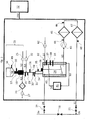
- FIG 1 the structure of the powder metering device 23 according to the invention is shown schematically, which is connected to a mixing container 42 via a measuring hose 33.
- the powder 59 is in a container 56, the opening 56a of which is directed downwards.
- the container 56 has a special closure head 57 and is inserted into the container receptacle 58, cf. also Figure 2 to 5 .
- the container receptacle 58 enables the powder 59 to run out dust-free into the measuring hose 33, from there into the connection head 34 and from there into the mixing container 42, where the powder 59 dissolves in the process liquid.
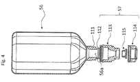
- the construction of the closure head 57 is shown in FIG Figure 2 to Figure 4 shown.
- the closure head 57 is - as in Figure 2 and Figure 3 shown - screwed onto the container thread 111 of the container 56 instead of a normal screw cap.
- commercially available containers 56 can be used.
- the closure head 57 is - as in the exploded view Figure 4 shown - from the following parts: a sealing element 112, namely an O-ring, a septum adapter 113, a septum 115 and a septum cap 114.
- the O-ring 112 seals between the container thread 111 or the lower end of the container 56 and the septum adapter 113. This prevents powder 59 from escaping at the connection point.
- the O-ring 112 is selected such that it effects a secure seal between the container thread 111 and the septum adapter 113 with all the tolerances that result from the individual parts when screwed together.
- locking or snap elements 116 are provided on the septum adapter 113 which, when the septum adapter 113 is completely screwed on, snap in / snap into complementary locking or snap elements 117 provided on the container 56 above the container thread 111.
- the outer wall of the container 56 extends radially slightly obliquely outwards and forms a sliding surface 117a, so that the septum adapter 113 can easily be screwed or pushed along this inclined outer wall 117a of the container 56, whereby it is pushed slightly outwards on its upward-facing side.
- the outer wall 117b of the container 56 extends radially inward and forms a blocking surface 117b running perpendicular to the longitudinal axis of the container 56, behind which a receiving space 117c is formed for the locking lug 116 on the septum adapter 113, which also extends radially inward.
- septum adapter 113 It must also be ensured that no powder 59 can escape between septum adapter 113 and septum 115.
- the septum cap 114 When the septum cap 114 is screwed onto the septum adapter 113, the septum 115 is pressed into the septum adapter 113 by the septum cap 114 and prevents powder 59 from escaping.
- the septum adapter 113 also has a slightly radially outwardly sliding surface 119a (cf. . Figure 3b, d ), so that the top of the septum cap 114 is pushed slightly outwards when screwed in and pushed upwards, and then, after passing over the radially inward surface 119b running at right angles to the longitudinal axis, snaps into place with the latching hook 118 in the free space 119c.
- the blocking surface 119b extends at right angles to the longitudinal axis of the septum adapter 113, the latching connection can no longer be released by a screwing-on movement or a pulling downward.
- the container 56, the septum adapter 113 and the septum cap 114 can be made from various metals, coated metals, plastics or glass. It is not imperative that all parts are made from the same material. Be preferred chemically resistant plastics are used. This ensures that even the smallest amounts of these plastics cannot adversely affect the process liquid.
- the container 56 As soon as the container 56 is completely emptied of the powder 59, it can be removed together with the closure head 57 from the container receptacle 58 and exchanged for a full container 56 'with the closure head 57.
- the closure head 57 can either be disposed of or recycled in a special process.
- the septum 115 is made of an elastomer.
- elastomers can be used such as natural rubber, synthetic rubber, ethylene propylene rubber EPM, fluoroelastomers FKM and FEPM, perfluoroelastomer Kalrez®, ethylene vinyl acetate EVA, butyl rubbers and others.
- butyl rubbers are particularly preferred as material for the septum, since they are very resistant to acids and alkalis and are elastic and have a Shore-A hardness of 40 to 85 and an elongation at break of 700%. Good chemical resistance is important, because in the unlikely event that even the smallest particles should get into the process liquid, this would not be adversely affected.
- the good elasticity and the good elongation at break enable the septum 115 to be reliably pierced in the container receptacle 58 without powder 59 escaping during this process, and also a secure closure of the septum 115 after the container 56 has been removed from the container receptacle 58 and the associated Withdrawal of the cannula 134. It is important that the septum 115 closes again automatically after the container 56 has been removed from the container receptacle 58 and thus prevents powder 59 from escaping from the container 56.
- the shape of the septum 115 can be a disk or, as in the in Figure 3 and 4th shown section can be designed as a plug.
- the shape of a stopper is preferred since this shape provides a secure seal between the septum adapter 113 and the septum 115 during piercing and subtraction results.
- the large sealing surface of the plug shape ensures a secure seal even when large forces are exerted on the septum 115, as happens when piercing or pulling off.
- the contact forces required by the septum cap 114 in the area of the septum 115 can be kept small by the plug shape of the septum 115 and still ensure a secure seal. This means that the required wall thicknesses can be kept thin. It is thus possible to make a fluid transition from the septum cap 114 to the septum 115, as in FIG Figure 3e and 5 shown in the transition region 120 to form.
- the container 56 has the shape of a funnel in the interior towards the container thread 111. And the septum adapter 113 is also designed inside the septum 115 as a funnel. This shape makes it possible to empty the entire powder 59 out of the container 56. Depending on the type of powder and container 56, it may be necessary to shake it so that the powder 59 falls safely down towards the septum 115 and the container 56 can be completely emptied.
- one or more vibrators 49 can be provided on the container 56 and / or one or more vibrators 50 on the septum adapter 113 ( Figure 1 , 2nd ).
- the location and the number of vibrators 49, 50 strongly depend on the type of powder 59 and the shape of the container 56.
- the vibrator 50 on the septum adapter 113 has proven to be very effective. This arrangement shakes enough to completely empty the container 56 without compressing the powder 59 so much that it becomes clogged. In order to make the effect of the shaking reproducible even after frequent changing of the container 56, the septum adapter 113 has a bulge 110 on its outer wall ( Figure 2 ), which ensures that the vibrations are always introduced into the septum adapter 113 at the same point regardless of the exact positioning of the vibrator 50.
- electromechanical, piezoelectric, pneumatic vibrators or eccentric vibrators can be used as vibrators.
- the container 56 with the closure head 57 and the septum adapter 113 is inserted into the container receptacle 58.
- the cannula 134 in the container receptacle 58 is inserted into the septum 115, and the powder 59 trickles downward in the cannula 134 (cf. Figure 5 , Figure 8 ).
- gas is pressed into the powder trickling down in the cannula 134 with the aid of the fluidization pump 25 in order to fluidize it.
- the gas through the in Figure 7 holes 139 shown in the outer wall of the cannula 134 passed.
- the powder in the area of the cannula has a different bulk density depending on the fill level of the container.
- non-reproducible bulk densities in the measuring system can also result from a negative pressure in the container, since gas is then drawn into the container from the measuring system against the flow direction of the powder. In this respect, it is necessary to replace the volume of the powder removed from the container with gas in order to avoid non-reproducible bulk densities in the measuring system.
- the powder is fluidized prior to the transfer into the measuring system via the fluidization pump 25, with which gas is pressed into the powder trickling down, in such a way that the flow of the gas changes over time during the fluidization.
- the fluidization is carried out before opening the pinch valve 28.
- the pump 25 is controlled in such a way that the same airflow-time profile as in FIG Fig. 11 shown.
- a further improvement in the reproducibility of the bulk densities can be achieved in a further variant by adapting the airflow-time profile to the respective fill level of the container.
- the total gas volume for the fluidization corresponds approximately to 0.3 to 3.0 times and preferably 0.5 to 2.0 times the volume of the measuring system (l * di 2 * ⁇ / 4).
- the time course of the gas flow essentially determines the degree of expansion of the gas cushion in the powder in the area of the cannula. It is important that the gas is not only stored in the cannula, but also exits the cannula into the container. It is even important that most of the gas gets into the bottom of the container. Therefore, the largest amount of gas is forced into the powder at the end of the fluidization.
- FIG 11 the time course of the gas flow during fluidization by means of a pump is shown.
- the flow of the gas preferably initially increases slowly and reaches maximum flow velocity before the end of the fluidization.
- a time-controlled valve can be used instead of the pump.
- various gases can be used, dry and oil-free air, nitrogen and argon being the most common. Nitrogen and argon are often used when the powder can oxidize or is hygroscopic, for example.
- the container receptacle 58 is suctioned off permanently or temporarily, depending on the application, via the suction line 63, which extends above the fluidization line 52.
- the dust filter 26 ( Figure 1 ) prevents particles from getting into the exhaust air pump 27.
- This arrangement which is shown schematically in Figure 1 can also be replaced by a central exhaust air system.
- the suction line 63 is connected directly to the central exhaust system.
- the output of the dust filter 26 can also be connected to an exhaust air system, which prevents particles from getting into the exhaust air system because they are retained by the dust filter 26.
- FIG 5 the longitudinal section through the container receptacle 58 with the closure head 57 attached and not pierced is shown.
- the closure head 57 is inserted into the receptacle 131 of the container receptacle 58.
- the receiving cup 131 is designed such that the closure head 57 is inserted into the receiving cup 131 in a centered manner.
- This is shown by the three cams 137 on the receiving cup 131, cf. Figure 6 , reached. More than three cams 137 can also be provided.
- Spacers 138 are also provided, which - together with the cams 137 - provide a defined air gap 200 between the closure head 57 and the receptacle 131. There may also be several spacers 138.
- Flow velocities of 2 - 35 m / s are required, depending on the properties of the powder 59 and the materials used for the production of the receptacle 131, septum cap 114 and septum 115 and their surface properties.
- FIG. 5b the air flow in the gap 200 is shown in dashed lines.
- the air flow is generated by suction of the ambient air via the suction line 63.
- the air is sucked in between the receiving cup 131 and the closure head 57 and through the Center bore in the receiving cup 131 along the cannula 134 for connecting the suction line 63 in the lower part 133.
- the septum cap 114 which partially engages under the septum 115 in its edge region from below, has a rounded edge 135 in the direction of the center of the septum 115, as in FIG Figure 5b shown, which is designed aerodynamically.
- the central area of the septum 115 does not rest on the septum cap 114, but is accessible.
- the receptacle 131 has on its upward-facing side opposite the center region 120 of the septum 115 a rounding 136 corresponding to the underside of the rounded edge 135 of the septum cap 114, so that the air flow is directed upwards in the direction of the septum 115, such as in Figure 7b shown. This ensures the best possible flow against the septum 115. This flow against the septum 115 ensures that when the septum 115 is pierced with the cannula 134 or when the cannula 134 is pulled out, particles that fall out are sucked off in a targeted manner. This ensures that no particles get caught on the septum 115 or the closure head 57.
- the container 56 can thus be removed from the container receptacle 58 without the risk that particles can escape into the environment.
- a compression spring 132 presses the receiving cup 131 up to a stop 131a in the guide tube 130 of the container receptacle 58.
- the spring 132 is preloaded such that the septum 115 cannot be pierced by the cannula 134 due to the weight of the container 56. This prevents an uncontrolled puncturing of the septum 115 through the cannula 134.
- a Controlled puncturing of the septum 115 with a movement that is as uniform as possible is necessary to prevent powder 59 from escaping when the septum 115 is pierced.
- a toggle lever 141 can be used, as in Figure 7a and Figure 7b shown to push the container 56 down to pierce the septum 115 with the cannula 134, cf. Figure 5 , Figure 8 . If the toggle lever 141 is released again, the container 56 is pressed against the toggle lever 141 by means of the spring 132, so that a controlled withdrawal of the container 56 with the closure head 57 with the septum 115 from the cannula 134 is ensured.
- automatable drives with or without toggle lever 141 such as pneumatic, hydraulic or electrical systems can also be used.
- the cannula 134 penetrates the septum 115 to such an extent that the ground tip of the cannula 134 comes to rest in the interior of the container 56, so that the powder can trickle into the cannula.
- the shape of the tip and the grinding of the cannula 134 are decisive. It has been found that the ratio of the thickness of the septum 115 to the outer cannula diameter in the range from 0.4 to 1.0 is ideal.
- Various cuts can be used on cannula 134. The best known are lancet cut, facet cut and others that are known from medicine. It is important that no hole is punched into the septum 115 when piercing, but that the entire septum 115 is only pierced and that parts of the septum 115 do not get into the cannula 134 or into the powder 59.
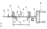
- the powder metering device With the powder metering device according to the invention, a certain amount of powder 59 can now be metered as follows as required. If the septum 115 is pierced with the cannula 134, the powder 59 trickles through the cannula 134 into the measuring tube 33 Figure 10 the measuring system is shown in section and in Figure 11 schematically. If the pinch valve 28 is closed, the measuring hose 33 fills up to Pinch valve 28. If the pinch valve 28 is open and the pinch valve 31 is closed, the measuring hose 33 fills from the container 56 to the pinch valve 31. If the pinch valve 28 is closed and the pinch valve 31 is opened, the powder trickles between the pinch valves 28 and 31 through the connection head 34 into the mixing container 42.
- the volume of the metered powder 59 is calculated from the distance l and the inner diameter di of the measuring tube 33, as in Figure 10 shown.
- the amount of powder 59 to be metered can be adjusted by varying the distance between the two pinch valves 28 and 31.
- gas can be pumped into the blow-out nozzle 140 via the hose 53 by means of the pump 32. This serves to press the powder 59 out of the measuring tube 33 in a controlled manner.
- the blow-out nozzle 140 is mounted immediately after the upper pinch valve 28. Dry air, nitrogen, argon or other suitable gases can be used.
- a vibrator 51 can also be attached to the measuring hose 33 in order to guarantee that the powder 59 completely trickles out. Blow-out nozzle 140 and vibrator 51 can also be used together.
- a time-controlled valve with or without a throttle can also be used.
- the measuring hose 33 should be made of an elastic material with good resilience. Suitable hose materials are silicone, neoprene, marprene, fluoroelastomer, PFL-reinforced fluoroelastomers and others.
- the measuring tube 33 can also be constructed in rigid tubes and can be designed with an elastic tube only in the area of the pinch valves 28 and 31. Since the tolerances of the inner diameter of elastic hoses are generally greater than those of pipes, the metering volume from station to station is more reproducible for pipes. With the described construction of a measuring hose 33 (with or without pipes), a repeatability of the metered volume of ⁇ 1% can be achieved.
- connection head 34 is kept at a higher temperature than the ambient temperature. This prevents blockages due to moisture at the outlet of the connection head 34.
- the connection head 34 can by means of a heating cartridge and a temperature sensor, in Figure 1 shown as heater 35, are kept at a defined temperature.
- the temperature of the connection head 34 can be achieved using other media, for example with hot fluids or gases.
- the process management system 12 can set the temperature of the connection head 34 in such a way that there is no condensation on the connection head 34.
- the gas space above the process liquid 24 can be specifically flushed with gas via the connection 61 via the pump 62.
- Common gases are dry air, nitrogen and argon. By introducing gas, the moisture in the room can be reduced and the outlet on the connection head 34 can thus be prevented from becoming blocked.
- the oxidation of the powder 59 and the process liquid 24 can also be reduced or prevented by using appropriate gases.
- a time-controlled valve with or without a throttle can also be used.
- the powder sensor 29 can be used to determine whether the measuring tube 33 between the pinch valves 28 and 31 is completely filled.
- the powder sensor 30 can also be used to determine whether the measuring tube 33 has emptied after the pinch valve 31 has been opened.
- Measuring principles suitable for powder sensors 29 and 30 are, for example, capacitive, ultrasonic or infrared measurement
- the powder 59 leaves the connection head 34, it falls into the mixing container or dissolving container 42, where the powder 59 mixes or dissolves with the process liquid 24.
- the fill level in the mixing container 42 of the process liquid 24 is regulated so that it is held between the fill level sensors 37 and 38.
- the valves 19, 18, 21 and pump 43 are available to the process management system 12.
- the process management system 12 regulates the Level so that it swings back and forth between the level sensors 37 and 38. Deposits of powder 59 on the walls of the mixing container 42 are thus prevented.
- a continuous fill level measurement can be used to ensure better fill level control.
- an agitator 36 is integrated in the mixing container 42. This is controlled by the process management system 12.
- Figure 11 a cross section through the mixing container 42 with a hydraulic mixer is shown.
- Process liquids 24 often have an elevated temperature of up to 90 ° C.
- the mixing container 42 can be designed with double walls. If an exothermic reaction takes place when the powder 59 is dissolved, it is necessary to dissipate the energy produced. This can be done by means of a temperature control system 41.
- the cooling or heating liquid is pumped by the temperature control system 41 via the line 54 into the intermediate space 40 and back via line 55 into the temperature control system 41.
- the materials for the mixing container 42 must be selected according to the application. Fluoridated plastics in particular are used because they are temperature-resistant and have very good chemical resistance.
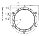
- the inlet into the mixing container 42 is equipped with an overflow weir 161.
- the process liquid 24 is fed into the inlet channel 160 via the line 20 (in Figure 12 shown).
- Line 20 ( Figure 1 ) is connected to the connection 162, which tangents the process liquid 24 in guides the inlet channel 160, in Figure 13 shown.
- An almost uniform pressure distribution in the inlet channel 160 is achieved by this tangential introduction.
- the process liquid 24 thus flows uniformly through the bores 163 to the overflow weir 161. From the overflow weir 161, the process liquid 24 flows down the wall along the mixing container 42 and permanently washes any powder residues into the process liquid 24 and thus prevents powder 59 from accumulating on the side walls.
- the process management system 12 can conduct the process liquid 24 permanently through the mixing container 42, and the valve 18 is closed and the valves 19 and 21 are open. Or valves 19 and 21 are closed and valve 18 opened before the powder metering, then the desired amount of powder 59 is added to the mixing container 42 and the powder 59 is mixed or dissolved for a certain time. Thereafter, valve 18 is closed and valves 19 and 21 opened, and pump 43 sucks process liquid from mixing container 42 via line 60 and maintains the circulation. If a hydraulic mixer is used, pump 43 and mixer can be integrated into one another.
- the process liquid 24 may be cleaned from unwanted particles after the powder 59 has been dissolved. This can be done using one or more filters 45 and 47. It may also be necessary for one of the filters 45, 47 to be designed as an activated carbon filter in order to filter out unwanted connections.
- the pressure sensors 44, 46 and 48 are for monitoring the filters 45, 47 and can detect clogging. Centrifuges can also be used.
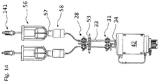
- two powder metering devices 23 can be provided which use a common connection head 34, as in FIG Figure 14 shown.
- the dosing process does not have to be interrupted when a container 56 becomes empty.
- the process management system 12 then automatically switches from empty to full container 56. Now the operating personnel has time, the empty one Replace container 56 with a full one without interrupting the dosing process.
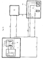
- the workpieces are covered with a metal layer in the production machine 1, Figure 15 and 16 .
- the cathode 5 is electrically connected to the workpiece in the deposition chamber 2.
- the anode 6 can be made of an inert material such as titanium, platinum or stainless steel or of the material to be deposited such as copper or nickel.
- the quantity of substance deposited on the workpiece is determined by the quantity of charge Q, which is calculated from the current intensity I and the time t, from the current source 7.
- the process chamber 9 flows from tank 4 to the deposition chamber 2 in order to ensure a constant double layer on the cathode 5.
- the process liquid 24 is circulated in the tank 4 from the tank 4 with the circulation pump 8.
- Particulate filters can be installed after the process pump 9 and the circulation pump 8 (not shown).
- a small amount of the process liquid 24 is fed from the circulation line 3 to the process management system 12 after the circulation pump 8 via the test line 11.
- the process management system 12 determines the concentration of the individual components from which the process liquid 24 is composed.
- the production machine 1 and the process management system 12 exchange data via the communication line 10. These data are required, among other things, to calculate the metering quantities of individual post-metering concentrations 16 by the process management system 12.
- the replenishment unit 14 is controlled by the process management system 12 via the communication line 13.
- the process management system 12 continuously calculates the on the basis of the analysis data and the data of the production machine 1 required metering volumes of the individual metering concentrations 16 and monitors the metering process.
- the individual pumps 15 pump the concentrates via the replenishment lines 17 into the circulation line 3.
- the connections of the replenishment lines 17 must be attached to the circulation line 3 after the test line 11 has left, so that over-concentrated process liquid 24 is prevented from reaching the process management system 12, incorrect ones Analysis results are generated and incorrect replenishment quantities are calculated.
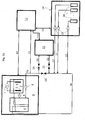
- FIG 16 the system is off Figure 15 to which the powder metering device 23 according to the invention is connected in addition to the associated lines and valves.
- the powder metering device 23 is controlled and monitored by the process management system 12. The data required for this are exchanged between the systems via the data line 150, similar to that in FIG Figure 15 Post-metering unit 14 described.
- the circulation line 3 is divided by the bypass valve 18 into the circulation line 3a and circulation line 3b.
- the process liquid 24 in which the powder 59 is dissolved is fed to the powder metering device 23 via the feed valve 19 and the feed line 20.
- the process liquid 24 with the dissolved powder 59 is fed into the circulation line 3b via the return line 22 and the return valve 21.
- the bypass valve 18 is closed and the circulation is permanently passed through the powder metering device 23. This ensures that there are no stagnant process fluids 24 in the entire system. With longer dissolving times of the powder 59, it may be necessary to open the bypass valve 18 and to close the inlet valve 19 and the return valve 21 during the dissolving time. This ensures that the other functionalities as in Fig. 15 described continue to work without restrictions. After the dissolution time, the bypass valve 18 is closed and the inlet valve 19 and the return valve 21 are opened. The return valve 21 can also be replaced by a check valve if the powder metering device 23 is constructed accordingly.
Landscapes
- Chemical & Material Sciences (AREA)
- Physics & Mathematics (AREA)
- Fluid Mechanics (AREA)
- General Physics & Mathematics (AREA)
- Organic Chemistry (AREA)
- Chemical Kinetics & Catalysis (AREA)
- Feeding, Discharge, Calcimining, Fusing, And Gas-Generation Devices (AREA)
- Basic Packing Technique (AREA)
Applications Claiming Priority (3)
| Application Number | Priority Date | Filing Date | Title |
|---|---|---|---|
| DE102016111214.3A DE102016111214B3 (de) | 2016-06-20 | 2016-06-20 | Vorrichtung zur Pulverdosierung für chemische Produktionsprozesse unter Reinraumbedingungen, Verwendung derselben und Zudosierungsverfahren |
| EP17715054.7A EP3472574B1 (fr) | 2016-06-20 | 2017-03-14 | Procédé de dosage de poudre pour des processus de production chimiques dans des conditions de salle blanche, utilisation de ce procédé et procédé d'addition dosée |
| PCT/EP2017/055944 WO2017220219A1 (fr) | 2016-06-20 | 2017-03-14 | Procédé de dosage de poudre pour des processus de production chimiques dans des conditions de salle blanche, utilisation de ce procédé et procédé d'addition dosée |
Related Parent Applications (2)
| Application Number | Title | Priority Date | Filing Date |
|---|---|---|---|
| EP17715054.7A Division EP3472574B1 (fr) | 2016-06-20 | 2017-03-14 | Procédé de dosage de poudre pour des processus de production chimiques dans des conditions de salle blanche, utilisation de ce procédé et procédé d'addition dosée |
| EP17715054.7A Division-Into EP3472574B1 (fr) | 2016-06-20 | 2017-03-14 | Procédé de dosage de poudre pour des processus de production chimiques dans des conditions de salle blanche, utilisation de ce procédé et procédé d'addition dosée |
Publications (2)
| Publication Number | Publication Date |
|---|---|
| EP3650818A1 true EP3650818A1 (fr) | 2020-05-13 |
| EP3650818B1 EP3650818B1 (fr) | 2021-05-19 |
Family
ID=58464505
Family Applications (2)
| Application Number | Title | Priority Date | Filing Date |
|---|---|---|---|
| EP17715054.7A Active EP3472574B1 (fr) | 2016-06-20 | 2017-03-14 | Procédé de dosage de poudre pour des processus de production chimiques dans des conditions de salle blanche, utilisation de ce procédé et procédé d'addition dosée |
| EP19212089.7A Active EP3650818B1 (fr) | 2016-06-20 | 2017-03-14 | Dispositif de dosage de poudre pour processus de production chimiques dans des conditions de salle blanche et son utilisation |
Family Applications Before (1)
| Application Number | Title | Priority Date | Filing Date |
|---|---|---|---|
| EP17715054.7A Active EP3472574B1 (fr) | 2016-06-20 | 2017-03-14 | Procédé de dosage de poudre pour des processus de production chimiques dans des conditions de salle blanche, utilisation de ce procédé et procédé d'addition dosée |
Country Status (8)
| Country | Link |
|---|---|
| US (2) | US10996093B2 (fr) |
| EP (2) | EP3472574B1 (fr) |
| JP (1) | JP6617207B2 (fr) |
| KR (1) | KR102356797B1 (fr) |
| CN (1) | CN109416271B (fr) |
| DE (1) | DE102016111214B3 (fr) |
| TW (1) | TWI736636B (fr) |
| WO (1) | WO2017220219A1 (fr) |
Families Citing this family (7)
| Publication number | Priority date | Publication date | Assignee | Title |
|---|---|---|---|---|
| DE102016111214B3 (de) | 2016-06-20 | 2017-06-29 | Ancosys Gmbh | Vorrichtung zur Pulverdosierung für chemische Produktionsprozesse unter Reinraumbedingungen, Verwendung derselben und Zudosierungsverfahren |
| EP3457094A1 (fr) * | 2017-09-18 | 2019-03-20 | Balda Medical GmbH & Co. KG | Dispositif de dosage et de distribution de matériau et procédé de fonctionnement d'un tel dispositif |
| WO2020175352A1 (fr) | 2019-02-28 | 2020-09-03 | 三菱マテリアル株式会社 | Solution aqueuse de sulfonate d'étain à concentration élevée et son procédé de production |
| CN112098268A (zh) * | 2020-09-16 | 2020-12-18 | 巫协森 | 线上测量溶液自动校正液位、容量与浓度方法及系统 |
| DE102020125653B3 (de) * | 2020-10-01 | 2021-11-04 | Fette Compacting Gmbh | Sensoranordnung für eine Produktionseinrichtung sowie Verfahren zum Transferieren eines Sensors in ein Gehäuse einer Produktionseinrichtung und aus einem Gehäuse einer Produktionseinrichtung |
| DE102021101833B3 (de) * | 2021-01-27 | 2022-01-20 | Syntegon Technology Gmbh | Vorrichtung zur Dosierung eines Pulvers, insbesondere eines pulverförmigen Pharmazeutikums |
| CN117303022A (zh) * | 2023-09-27 | 2023-12-29 | 晟盈半导体设备(江苏)有限公司 | 氧化铜粉末自动计量和添加装置 |
Citations (6)
| Publication number | Priority date | Publication date | Assignee | Title |
|---|---|---|---|---|
| FR2219894A1 (fr) * | 1973-03-02 | 1974-09-27 | Maximilianshuette Eisenwerk | |
| DE3026816A1 (de) * | 1980-07-16 | 1982-02-04 | Hoechst Ag, 6000 Frankfurt | Verfahren und vorrichtung zur dosierung kleiner mengen suspension |
| US4850978A (en) * | 1987-10-29 | 1989-07-25 | Baxter International Inc. | Drug delivery cartridge with protective cover |
| DE102005005359A1 (de) * | 2005-02-02 | 2006-08-10 | Siemens Ag | Verfahren zum Kaltgasspritzen und für dieses Verfahren geeignete Beschichtungsanlage |
| US20090078194A1 (en) | 2007-09-20 | 2009-03-26 | Ikuo Sugimoto | Powdering device for powdering printed sheet |
| EP2311513A1 (fr) * | 2009-10-16 | 2011-04-20 | Sanofi-Aventis Deutschland GmbH | Ensemble support de cartouche pour dispositif d'administration de médicaments |
Family Cites Families (28)
| Publication number | Priority date | Publication date | Assignee | Title |
|---|---|---|---|---|
| DE2062513B2 (de) * | 1970-12-18 | 1979-02-15 | Hoechst Ag, 6000 Frankfurt | Dosiervorrichtung zum Dosieren von Pulvern |
| FR2575825B1 (fr) * | 1985-01-04 | 1987-04-17 | Saint Gobain Vitrage | Procede et dispositif pour le dosage de matieres pulverulentes |
| US5147551A (en) * | 1990-04-20 | 1992-09-15 | Dynatech Precision Sampling Corporation | Solids and semi-solids sampling apparatus, method, and fluid injection apparatus |
| US5432098A (en) * | 1994-10-31 | 1995-07-11 | Dynatech Precision Sampling Corporation | Apparatus, and process, for automatically sampling solids and semi-solids materials for analysis |
| US5826633A (en) | 1996-04-26 | 1998-10-27 | Inhale Therapeutic Systems | Powder filling systems, apparatus and methods |
| US5777245A (en) | 1996-09-13 | 1998-07-07 | Applied Materials, Inc. | Particle dispersing system and method for testing semiconductor manufacturing equipment |
| US6077713A (en) * | 1998-06-30 | 2000-06-20 | Dade Behring Inc. | Method and apparatus for extracting liquid samples from a closed container |
| DE19836014A1 (de) * | 1998-08-10 | 2000-02-17 | Weitmann & Konrad Fa | Verfahren und Vorrichtung zum Bepudern bedruckter Bogen |
| JP4026994B2 (ja) * | 1998-08-27 | 2007-12-26 | 三井化学株式会社 | 粉体定量供給装置及びそれを用いた粉体定量供給方法 |
| CA2445516C (fr) * | 2001-04-26 | 2007-11-20 | New England Pharmaceuticals, Inc. | Distributeur-doseur destine a des agents liquides et en poudre |
| US6715640B2 (en) * | 2001-07-09 | 2004-04-06 | Innovative Technology, Inc. | Powder fluidizing devices and portable powder-deposition apparatus for coating and spray forming |
| US6684917B2 (en) * | 2001-12-17 | 2004-02-03 | The University Of Western Ontario | Apparatus for volumetric metering of small quantity of powder from fluidized beds |
| JP3826063B2 (ja) * | 2002-04-10 | 2006-09-27 | 愛三工業株式会社 | 粉体供給装置及び粉体供給方法 |
| US7082848B2 (en) * | 2002-09-16 | 2006-08-01 | Fjerdingstad Soelve | Method of transferring a representative fluid sample from a pressurized source into a sample bottle |
| FR2890649B1 (fr) * | 2005-09-13 | 2010-04-16 | Lesaffre & Cie | Vanne de dosage comprenant un conduit interne fixe et un manchon externe mobile. |
| US7993459B2 (en) | 2005-10-24 | 2011-08-09 | Global Oled Technology Llc | Delivering particulate material to a vaporization zone |
| EP2668970B1 (fr) * | 2006-10-25 | 2016-07-06 | Novartis AG | Appareil de dispersion de poudre |
| MY152036A (en) | 2008-12-08 | 2014-08-15 | Calyxo Gmbh | Thin-film deposition and recirculation of a semi-conductor material |
| WO2011015217A1 (fr) | 2009-08-06 | 2011-02-10 | Harro Höfliger Verpackungsmaschinen GmbH | Système de remplissage permettant le dosage de poudre et procédé pour faire fonctionner un tel système de remplissage |
| EP2488236B1 (fr) * | 2009-10-16 | 2015-05-06 | Sanofi-Aventis Deutschland GmbH | Ensemble support de cartouche pour dispositif d'administration de médicaments |
| US9284643B2 (en) | 2010-03-23 | 2016-03-15 | Pneumaticoat Technologies Llc | Semi-continuous vapor deposition process for the manufacture of coated particles |
| US9465317B2 (en) * | 2013-02-25 | 2016-10-11 | Ricoh Company, Ltd. | Nozzle insertion member, powder container, and image forming apparatus |
| CN203638117U (zh) * | 2014-01-07 | 2014-06-11 | 无锡大东机械制造有限公司 | 立式粉料分离式装箱吸气定量包装秤 |
| CN103808382B (zh) * | 2014-02-28 | 2016-08-17 | 济南鲁纺仪佳自控技术有限公司 | 隔离式粉料流量计量装置 |
| MX2016013590A (es) * | 2014-04-17 | 2017-05-08 | Mezurware Llc | Un dispositivo dispensador para dispensar un producto en polvo. |
| CA3011508A1 (fr) * | 2016-01-19 | 2017-07-27 | Biogen Ma Inc. | Dispositif de dosage medical |
| PL3238832T5 (pl) | 2016-04-29 | 2024-06-03 | Wagner International Ag | Urządzenie transportujące proszek do transportowania proszku powlekającego do aplikatora proszku, instalacja do powlekania proszkowego i sposób obsługi urządzenia transportującego proszek |
| DE102016111214B3 (de) | 2016-06-20 | 2017-06-29 | Ancosys Gmbh | Vorrichtung zur Pulverdosierung für chemische Produktionsprozesse unter Reinraumbedingungen, Verwendung derselben und Zudosierungsverfahren |
-
2016
- 2016-06-20 DE DE102016111214.3A patent/DE102016111214B3/de not_active Withdrawn - After Issue
-
2017
- 2017-03-14 US US16/078,998 patent/US10996093B2/en active Active
- 2017-03-14 EP EP17715054.7A patent/EP3472574B1/fr active Active
- 2017-03-14 WO PCT/EP2017/055944 patent/WO2017220219A1/fr not_active Ceased
- 2017-03-14 EP EP19212089.7A patent/EP3650818B1/fr active Active
- 2017-03-14 JP JP2018559998A patent/JP6617207B2/ja active Active
- 2017-03-14 KR KR1020197001874A patent/KR102356797B1/ko active Active
- 2017-03-14 CN CN201780038481.7A patent/CN109416271B/zh active Active
- 2017-06-16 TW TW106120171A patent/TWI736636B/zh active
-
2020
- 2020-03-06 US US16/812,020 patent/US10982987B2/en active Active
Patent Citations (6)
| Publication number | Priority date | Publication date | Assignee | Title |
|---|---|---|---|---|
| FR2219894A1 (fr) * | 1973-03-02 | 1974-09-27 | Maximilianshuette Eisenwerk | |
| DE3026816A1 (de) * | 1980-07-16 | 1982-02-04 | Hoechst Ag, 6000 Frankfurt | Verfahren und vorrichtung zur dosierung kleiner mengen suspension |
| US4850978A (en) * | 1987-10-29 | 1989-07-25 | Baxter International Inc. | Drug delivery cartridge with protective cover |
| DE102005005359A1 (de) * | 2005-02-02 | 2006-08-10 | Siemens Ag | Verfahren zum Kaltgasspritzen und für dieses Verfahren geeignete Beschichtungsanlage |
| US20090078194A1 (en) | 2007-09-20 | 2009-03-26 | Ikuo Sugimoto | Powdering device for powdering printed sheet |
| EP2311513A1 (fr) * | 2009-10-16 | 2011-04-20 | Sanofi-Aventis Deutschland GmbH | Ensemble support de cartouche pour dispositif d'administration de médicaments |
Also Published As
| Publication number | Publication date |
|---|---|
| KR102356797B1 (ko) | 2022-02-03 |
| US20200348161A1 (en) | 2020-11-05 |
| US20190025107A1 (en) | 2019-01-24 |
| KR20190020107A (ko) | 2019-02-27 |
| CN109416271A (zh) | 2019-03-01 |
| WO2017220219A1 (fr) | 2017-12-28 |
| TWI736636B (zh) | 2021-08-21 |
| EP3472574A1 (fr) | 2019-04-24 |
| EP3650818B1 (fr) | 2021-05-19 |
| US10996093B2 (en) | 2021-05-04 |
| TW201800726A (zh) | 2018-01-01 |
| DE102016111214B3 (de) | 2017-06-29 |
| US10982987B2 (en) | 2021-04-20 |
| EP3472574B1 (fr) | 2021-03-03 |
| JP6617207B2 (ja) | 2019-12-11 |
| CN109416271B (zh) | 2021-01-05 |
| JP2019521839A (ja) | 2019-08-08 |
Similar Documents
| Publication | Publication Date | Title |
|---|---|---|
| EP3472574B1 (fr) | Procédé de dosage de poudre pour des processus de production chimiques dans des conditions de salle blanche, utilisation de ce procédé et procédé d'addition dosée | |
| DE2614787C3 (de) | Vorrichtung zum Entnehmen von Fliissigkeitsproben | |
| DE2904644A1 (de) | Vorrichtung zum praeparieren, insbesondere markieren, von biologischen proben | |
| WO1997025456A1 (fr) | Procede de maintien de concentrations constantes de substances contenues dans un bain de traitement galvanoplastique | |
| DE102023123691A1 (de) | Abscheidungsstation sowie Vorrichtung zur Erzeugung von Kontaktmetallisierungen | |
| EP0445120A1 (fr) | Dispositif pour appliquer et/ou oter des revetements sur des pieces. | |
| WO2023208742A1 (fr) | Dispositif et procédé de fabrication de particules solides | |
| EP2849894B1 (fr) | Dispositif pour mélanger des liquides | |
| DE2508066A1 (de) | Dosiergeraet fuer pulverfoermiges gut | |
| DE20300046U1 (de) | Rotationsverdampfer zum automatischen Destillieren | |
| DE69804512T2 (de) | Quecksilbertropfelektrode mit quecksilberreinigung und -recycling durch kontakt mit sauerstoffreichem wasser | |
| DE2918768A1 (de) | Verfahren zum entnehmen von stoffproben aus einem behaelter und vorrichtung zur durchfuehrung des verfahrens | |
| DE102018112308B4 (de) | Magnesium-Luft-Batterie und Verfahren zum kontinuierlichen Betreiben derselben | |
| DE10050636A1 (de) | Verfahren und Vorrichtung zur Oberflächen-Behandlung von Gegenständen | |
| DE1925740C3 (de) | Vorrichtung zur Durchführung von organischen Dimerisationsreaktionen | |
| DE3014021A1 (de) | Verfahren zum elektrolytischen rueckgewinnen von edelmetallen aus edelmetallsalzloesungen und vorrichtung zu seiner durchfuehrung | |
| DE2306592C3 (de) | Vorrichtung zum Aufschluß und Verarbeitung von Aktiniden-Aluminium-Legierungen oder aluminiumhaltige Cermets | |
| DE2816924C2 (fr) | ||
| DE102010053693A1 (de) | Verfahren zur chemischen Reinigung von metallurgischem Silizium und Vorrichtung zur Durchführung des Verfahrens | |
| DE102014007057B3 (de) | Verfahren und Vorrichtung zur Behandlung von empfindlichen plattenförmigen und flexiblen Werkstücken durch Führung der selbigen in einer Kanalströmung | |
| WO1991005888A1 (fr) | Installation de gravure et proceder pour graver des objets | |
| DE8803939U1 (de) | Schmelzbehälter für thermoplastische, hochpolymere Werkstoffe | |
| DE102012107393A1 (de) | Vorrichtung und Verfahren zur Herstellung galvanischer Überzüge | |
| DE10205586A1 (de) | Verfahren und Vorrichtung zur galvanischen Beschichtung von Endlosmaterial |
Legal Events
| Date | Code | Title | Description |
|---|---|---|---|
| PUAI | Public reference made under article 153(3) epc to a published international application that has entered the european phase |
Free format text: ORIGINAL CODE: 0009012 |
|
| STAA | Information on the status of an ep patent application or granted ep patent |
Free format text: STATUS: THE APPLICATION HAS BEEN PUBLISHED |
|
| AC | Divisional application: reference to earlier application |
Ref document number: 3472574 Country of ref document: EP Kind code of ref document: P |
|
| AK | Designated contracting states |
Kind code of ref document: A1 Designated state(s): AL AT BE BG CH CY CZ DE DK EE ES FI FR GB GR HR HU IE IS IT LI LT LU LV MC MK MT NL NO PL PT RO RS SE SI SK SM TR |
|
| STAA | Information on the status of an ep patent application or granted ep patent |
Free format text: STATUS: REQUEST FOR EXAMINATION WAS MADE |
|
| 17P | Request for examination filed |
Effective date: 20200818 |
|
| RBV | Designated contracting states (corrected) |
Designated state(s): AL AT BE BG CH CY CZ DE DK EE ES FI FR GB GR HR HU IE IS IT LI LT LU LV MC MK MT NL NO PL PT RO RS SE SI SK SM TR |
|
| GRAJ | Information related to disapproval of communication of intention to grant by the applicant or resumption of examination proceedings by the epo deleted |
Free format text: ORIGINAL CODE: EPIDOSDIGR1 |
|
| STAA | Information on the status of an ep patent application or granted ep patent |
Free format text: STATUS: GRANT OF PATENT IS INTENDED |
|
| GRAP | Despatch of communication of intention to grant a patent |
Free format text: ORIGINAL CODE: EPIDOSNIGR1 |
|
| GRAS | Grant fee paid |
Free format text: ORIGINAL CODE: EPIDOSNIGR3 |
|
| INTG | Intention to grant announced |
Effective date: 20210316 |
|
| RIN1 | Information on inventor provided before grant (corrected) |
Inventor name: STAHL, JUERG Inventor name: POPOVA, IRENE Inventor name: RUECKEL, CHRISTIAN |
|
| GRAA | (expected) grant |
Free format text: ORIGINAL CODE: 0009210 |
|
| STAA | Information on the status of an ep patent application or granted ep patent |
Free format text: STATUS: THE PATENT HAS BEEN GRANTED |
|
| AC | Divisional application: reference to earlier application |
Ref document number: 3472574 Country of ref document: EP Kind code of ref document: P |
|
| AK | Designated contracting states |
Kind code of ref document: B1 Designated state(s): AL AT BE BG CH CY CZ DE DK EE ES FI FR GB GR HR HU IE IS IT LI LT LU LV MC MK MT NL NO PL PT RO RS SE SI SK SM TR |
|
| REG | Reference to a national code |
Ref country code: GB Ref legal event code: FG4D Free format text: NOT ENGLISH |
|
| REG | Reference to a national code |
Ref country code: CH Ref legal event code: EP |
|
| REG | Reference to a national code |
Ref country code: DE Ref legal event code: R096 Ref document number: 502017010433 Country of ref document: DE |
|
| REG | Reference to a national code |
Ref country code: AT Ref legal event code: REF Ref document number: 1394433 Country of ref document: AT Kind code of ref document: T Effective date: 20210615 |
|
| REG | Reference to a national code |
Ref country code: IE Ref legal event code: FG4D Free format text: LANGUAGE OF EP DOCUMENT: GERMAN |
|
| REG | Reference to a national code |
Ref country code: LT Ref legal event code: MG9D |
|
| REG | Reference to a national code |
Ref country code: NL Ref legal event code: MP Effective date: 20210519 |
|
| PG25 | Lapsed in a contracting state [announced via postgrant information from national office to epo] |
Ref country code: BG Free format text: LAPSE BECAUSE OF FAILURE TO SUBMIT A TRANSLATION OF THE DESCRIPTION OR TO PAY THE FEE WITHIN THE PRESCRIBED TIME-LIMIT Effective date: 20210819 Ref country code: FI Free format text: LAPSE BECAUSE OF FAILURE TO SUBMIT A TRANSLATION OF THE DESCRIPTION OR TO PAY THE FEE WITHIN THE PRESCRIBED TIME-LIMIT Effective date: 20210519 Ref country code: HR Free format text: LAPSE BECAUSE OF FAILURE TO SUBMIT A TRANSLATION OF THE DESCRIPTION OR TO PAY THE FEE WITHIN THE PRESCRIBED TIME-LIMIT Effective date: 20210519 Ref country code: LT Free format text: LAPSE BECAUSE OF FAILURE TO SUBMIT A TRANSLATION OF THE DESCRIPTION OR TO PAY THE FEE WITHIN THE PRESCRIBED TIME-LIMIT Effective date: 20210519 |
|
| PG25 | Lapsed in a contracting state [announced via postgrant information from national office to epo] |
Ref country code: LV Free format text: LAPSE BECAUSE OF FAILURE TO SUBMIT A TRANSLATION OF THE DESCRIPTION OR TO PAY THE FEE WITHIN THE PRESCRIBED TIME-LIMIT Effective date: 20210519 Ref country code: PL Free format text: LAPSE BECAUSE OF FAILURE TO SUBMIT A TRANSLATION OF THE DESCRIPTION OR TO PAY THE FEE WITHIN THE PRESCRIBED TIME-LIMIT Effective date: 20210519 Ref country code: NO Free format text: LAPSE BECAUSE OF FAILURE TO SUBMIT A TRANSLATION OF THE DESCRIPTION OR TO PAY THE FEE WITHIN THE PRESCRIBED TIME-LIMIT Effective date: 20210819 Ref country code: SE Free format text: LAPSE BECAUSE OF FAILURE TO SUBMIT A TRANSLATION OF THE DESCRIPTION OR TO PAY THE FEE WITHIN THE PRESCRIBED TIME-LIMIT Effective date: 20210519 Ref country code: RS Free format text: LAPSE BECAUSE OF FAILURE TO SUBMIT A TRANSLATION OF THE DESCRIPTION OR TO PAY THE FEE WITHIN THE PRESCRIBED TIME-LIMIT Effective date: 20210519 Ref country code: PT Free format text: LAPSE BECAUSE OF FAILURE TO SUBMIT A TRANSLATION OF THE DESCRIPTION OR TO PAY THE FEE WITHIN THE PRESCRIBED TIME-LIMIT Effective date: 20210920 Ref country code: GR Free format text: LAPSE BECAUSE OF FAILURE TO SUBMIT A TRANSLATION OF THE DESCRIPTION OR TO PAY THE FEE WITHIN THE PRESCRIBED TIME-LIMIT Effective date: 20210820 Ref country code: IS Free format text: LAPSE BECAUSE OF FAILURE TO SUBMIT A TRANSLATION OF THE DESCRIPTION OR TO PAY THE FEE WITHIN THE PRESCRIBED TIME-LIMIT Effective date: 20210919 |
|
| PG25 | Lapsed in a contracting state [announced via postgrant information from national office to epo] |
Ref country code: NL Free format text: LAPSE BECAUSE OF FAILURE TO SUBMIT A TRANSLATION OF THE DESCRIPTION OR TO PAY THE FEE WITHIN THE PRESCRIBED TIME-LIMIT Effective date: 20210519 |
|
| PG25 | Lapsed in a contracting state [announced via postgrant information from national office to epo] |
Ref country code: SK Free format text: LAPSE BECAUSE OF FAILURE TO SUBMIT A TRANSLATION OF THE DESCRIPTION OR TO PAY THE FEE WITHIN THE PRESCRIBED TIME-LIMIT Effective date: 20210519 Ref country code: ES Free format text: LAPSE BECAUSE OF FAILURE TO SUBMIT A TRANSLATION OF THE DESCRIPTION OR TO PAY THE FEE WITHIN THE PRESCRIBED TIME-LIMIT Effective date: 20210519 Ref country code: EE Free format text: LAPSE BECAUSE OF FAILURE TO SUBMIT A TRANSLATION OF THE DESCRIPTION OR TO PAY THE FEE WITHIN THE PRESCRIBED TIME-LIMIT Effective date: 20210519 Ref country code: DK Free format text: LAPSE BECAUSE OF FAILURE TO SUBMIT A TRANSLATION OF THE DESCRIPTION OR TO PAY THE FEE WITHIN THE PRESCRIBED TIME-LIMIT Effective date: 20210519 Ref country code: CZ Free format text: LAPSE BECAUSE OF FAILURE TO SUBMIT A TRANSLATION OF THE DESCRIPTION OR TO PAY THE FEE WITHIN THE PRESCRIBED TIME-LIMIT Effective date: 20210519 Ref country code: RO Free format text: LAPSE BECAUSE OF FAILURE TO SUBMIT A TRANSLATION OF THE DESCRIPTION OR TO PAY THE FEE WITHIN THE PRESCRIBED TIME-LIMIT Effective date: 20210519 Ref country code: SM Free format text: LAPSE BECAUSE OF FAILURE TO SUBMIT A TRANSLATION OF THE DESCRIPTION OR TO PAY THE FEE WITHIN THE PRESCRIBED TIME-LIMIT Effective date: 20210519 |
|
| REG | Reference to a national code |
Ref country code: DE Ref legal event code: R097 Ref document number: 502017010433 Country of ref document: DE |
|
| PLBE | No opposition filed within time limit |
Free format text: ORIGINAL CODE: 0009261 |
|
| STAA | Information on the status of an ep patent application or granted ep patent |
Free format text: STATUS: NO OPPOSITION FILED WITHIN TIME LIMIT |
|
| 26N | No opposition filed |
Effective date: 20220222 |
|
| PG25 | Lapsed in a contracting state [announced via postgrant information from national office to epo] |
Ref country code: IS Free format text: LAPSE BECAUSE OF FAILURE TO SUBMIT A TRANSLATION OF THE DESCRIPTION OR TO PAY THE FEE WITHIN THE PRESCRIBED TIME-LIMIT Effective date: 20210919 Ref country code: AL Free format text: LAPSE BECAUSE OF FAILURE TO SUBMIT A TRANSLATION OF THE DESCRIPTION OR TO PAY THE FEE WITHIN THE PRESCRIBED TIME-LIMIT Effective date: 20210519 |
|
| PG25 | Lapsed in a contracting state [announced via postgrant information from national office to epo] |
Ref country code: MC Free format text: LAPSE BECAUSE OF FAILURE TO SUBMIT A TRANSLATION OF THE DESCRIPTION OR TO PAY THE FEE WITHIN THE PRESCRIBED TIME-LIMIT Effective date: 20210519 |
|
| REG | Reference to a national code |
Ref country code: CH Ref legal event code: PL |
|
| REG | Reference to a national code |
Ref country code: BE Ref legal event code: MM Effective date: 20220331 |
|
| PG25 | Lapsed in a contracting state [announced via postgrant information from national office to epo] |
Ref country code: LU Free format text: LAPSE BECAUSE OF NON-PAYMENT OF DUE FEES Effective date: 20220314 Ref country code: LI Free format text: LAPSE BECAUSE OF NON-PAYMENT OF DUE FEES Effective date: 20220331 Ref country code: IE Free format text: LAPSE BECAUSE OF NON-PAYMENT OF DUE FEES Effective date: 20220314 Ref country code: CH Free format text: LAPSE BECAUSE OF NON-PAYMENT OF DUE FEES Effective date: 20220331 |
|
| PG25 | Lapsed in a contracting state [announced via postgrant information from national office to epo] |
Ref country code: BE Free format text: LAPSE BECAUSE OF NON-PAYMENT OF DUE FEES Effective date: 20220331 |
|
| PG25 | Lapsed in a contracting state [announced via postgrant information from national office to epo] |
Ref country code: MK Free format text: LAPSE BECAUSE OF FAILURE TO SUBMIT A TRANSLATION OF THE DESCRIPTION OR TO PAY THE FEE WITHIN THE PRESCRIBED TIME-LIMIT Effective date: 20210519 Ref country code: CY Free format text: LAPSE BECAUSE OF FAILURE TO SUBMIT A TRANSLATION OF THE DESCRIPTION OR TO PAY THE FEE WITHIN THE PRESCRIBED TIME-LIMIT Effective date: 20210519 |
|
| PG25 | Lapsed in a contracting state [announced via postgrant information from national office to epo] |
Ref country code: HU Free format text: LAPSE BECAUSE OF FAILURE TO SUBMIT A TRANSLATION OF THE DESCRIPTION OR TO PAY THE FEE WITHIN THE PRESCRIBED TIME-LIMIT; INVALID AB INITIO Effective date: 20170314 |
|
| PG25 | Lapsed in a contracting state [announced via postgrant information from national office to epo] |
Ref country code: MT Free format text: LAPSE BECAUSE OF FAILURE TO SUBMIT A TRANSLATION OF THE DESCRIPTION OR TO PAY THE FEE WITHIN THE PRESCRIBED TIME-LIMIT Effective date: 20210519 |
|
| REG | Reference to a national code |
Ref country code: DE Ref legal event code: R082 Ref document number: 502017010433 Country of ref document: DE |
|
| PG25 | Lapsed in a contracting state [announced via postgrant information from national office to epo] |
Ref country code: TR Free format text: LAPSE BECAUSE OF FAILURE TO SUBMIT A TRANSLATION OF THE DESCRIPTION OR TO PAY THE FEE WITHIN THE PRESCRIBED TIME-LIMIT Effective date: 20210519 |
|
| PGFP | Annual fee paid to national office [announced via postgrant information from national office to epo] |
Ref country code: GB Payment date: 20260324 Year of fee payment: 10 |
|
| PGFP | Annual fee paid to national office [announced via postgrant information from national office to epo] |
Ref country code: DE Payment date: 20260319 Year of fee payment: 10 |
|
| PGFP | Annual fee paid to national office [announced via postgrant information from national office to epo] |
Ref country code: AT Payment date: 20260320 Year of fee payment: 10 |
|
| PGFP | Annual fee paid to national office [announced via postgrant information from national office to epo] |
Ref country code: IT Payment date: 20260324 Year of fee payment: 10 |
|
| PGFP | Annual fee paid to national office [announced via postgrant information from national office to epo] |
Ref country code: FR Payment date: 20260320 Year of fee payment: 10 |