EP3650933B1 - Beleuchtungsvorrichtung, fahrzeugkomponente und fahrzeug - Google Patents
Beleuchtungsvorrichtung, fahrzeugkomponente und fahrzeug Download PDFInfo
- Publication number
- EP3650933B1 EP3650933B1 EP19206767.6A EP19206767A EP3650933B1 EP 3650933 B1 EP3650933 B1 EP 3650933B1 EP 19206767 A EP19206767 A EP 19206767A EP 3650933 B1 EP3650933 B1 EP 3650933B1
- Authority
- EP
- European Patent Office
- Prior art keywords
- illumination device
- reflection unit
- optical reflection
- unit
- reflective
- Prior art date
- Legal status (The legal status is an assumption and is not a legal conclusion. Google has not performed a legal analysis and makes no representation as to the accuracy of the status listed.)
- Active
Links
Images


Classifications
-
- F—MECHANICAL ENGINEERING; LIGHTING; HEATING; WEAPONS; BLASTING
- F21—LIGHTING
- F21S—NON-PORTABLE LIGHTING DEVICES; SYSTEMS THEREOF; VEHICLE LIGHTING DEVICES SPECIALLY ADAPTED FOR VEHICLE EXTERIORS
- F21S43/00—Signalling devices specially adapted for vehicle exteriors, e.g. brake lamps, direction indicator lights or reversing lights
- F21S43/30—Signalling devices specially adapted for vehicle exteriors, e.g. brake lamps, direction indicator lights or reversing lights characterised by reflectors
- F21S43/31—Optical layout thereof
-
- G—PHYSICS
- G03—PHOTOGRAPHY; CINEMATOGRAPHY; ANALOGOUS TECHNIQUES USING WAVES OTHER THAN OPTICAL WAVES; ELECTROGRAPHY; HOLOGRAPHY
- G03B—APPARATUS OR ARRANGEMENTS FOR TAKING PHOTOGRAPHS OR FOR PROJECTING OR VIEWING THEM; APPARATUS OR ARRANGEMENTS EMPLOYING ANALOGOUS TECHNIQUES USING WAVES OTHER THAN OPTICAL WAVES; ACCESSORIES THEREFOR
- G03B21/00—Projectors or projection-type viewers; Accessories therefor
-
- F—MECHANICAL ENGINEERING; LIGHTING; HEATING; WEAPONS; BLASTING
- F21—LIGHTING
- F21S—NON-PORTABLE LIGHTING DEVICES; SYSTEMS THEREOF; VEHICLE LIGHTING DEVICES SPECIALLY ADAPTED FOR VEHICLE EXTERIORS
- F21S43/00—Signalling devices specially adapted for vehicle exteriors, e.g. brake lamps, direction indicator lights or reversing lights
- F21S43/20—Signalling devices specially adapted for vehicle exteriors, e.g. brake lamps, direction indicator lights or reversing lights characterised by refractors, transparent cover plates, light guides or filters
-
- F—MECHANICAL ENGINEERING; LIGHTING; HEATING; WEAPONS; BLASTING
- F21—LIGHTING
- F21V—FUNCTIONAL FEATURES OR DETAILS OF LIGHTING DEVICES OR SYSTEMS THEREOF; STRUCTURAL COMBINATIONS OF LIGHTING DEVICES WITH OTHER ARTICLES, NOT OTHERWISE PROVIDED FOR
- F21V11/00—Screens not covered by groups F21V1/00, F21V3/00, F21V7/00 or F21V9/00
-
- G—PHYSICS
- G03—PHOTOGRAPHY; CINEMATOGRAPHY; ANALOGOUS TECHNIQUES USING WAVES OTHER THAN OPTICAL WAVES; ELECTROGRAPHY; HOLOGRAPHY
- G03B—APPARATUS OR ARRANGEMENTS FOR TAKING PHOTOGRAPHS OR FOR PROJECTING OR VIEWING THEM; APPARATUS OR ARRANGEMENTS EMPLOYING ANALOGOUS TECHNIQUES USING WAVES OTHER THAN OPTICAL WAVES; ACCESSORIES THEREFOR
- G03B21/00—Projectors or projection-type viewers; Accessories therefor
- G03B21/14—Details
- G03B21/28—Reflectors in projection beam
-
- F—MECHANICAL ENGINEERING; LIGHTING; HEATING; WEAPONS; BLASTING
- F21—LIGHTING
- F21W—INDEXING SCHEME ASSOCIATED WITH SUBCLASSES F21K, F21L, F21S and F21V, RELATING TO USES OR APPLICATIONS OF LIGHTING DEVICES OR SYSTEMS
- F21W2103/00—Exterior vehicle lighting devices for signalling purposes
- F21W2103/60—Projection of signs from lighting devices, e.g. symbols or information being projected onto the road
Definitions
- the invention refers to an illumination device, comprising at least one illuminant for emitting light; and an optical reflection unit, comprising at least one reflective surface; and at least one surface comprising at least one mask, wherein the optical reflection unit is configured to receive the light emitted from the at least one illuminant and project at least one of an image, a symbol, a logo, a pattern, and a legend on a projection surface.
- an illumination device typically includes a number of parts and components including, but not limited to, a condenser lens, a projector lens, a mask, among other components.
- Multiple illumination device components are typically combined into one housing to form the device.
- the components may be aligned with one another so that they share a single axis, and light from a light source may follow a path along the single axis so that an image from a mask is projected.
- DE 20 2008 016 695 U1 describes an illumination device having a so-called logo lamp in which an image or legend is projected onto a projection surface through the interaction of an illuminant, a condenser unit, a mask means and a lens unit.
- the illumination device is arranged in a rearview device realized as an external mirror in order to project an image or a legend onto a roadway or sidewalk.
- the individual components of the illumination device are arranged behind one another in a tubular housing. Because of the essentially vertical course of the optical path, the known illumination device in the external mirror is arranged essentially perpendicular to the projection surface.
- the illumination device can be integrated directly into an external mirror, or be attached into a corresponding receptacle on the external mirror. Indeed, the rigid arrangement of the individual components of the illumination device in the tubular housing makes it difficult to integrate the illumination device into or onto the external mirror because of the limited space.
- DE 101 34 594 A1 describes an illumination device which is adapted to project an object correlated with the driving situation into a surrounding area of a vehicle.
- DE 10 2004 050 600 A1 describes an illumination device for a vehicle for generating a light field in the region of the vehicle door.
- US 2009/0161379 A1 describes the projection of a pattern onto a subsurface using an illumination device in an external mirror.
- US 2018/154819 A1 describes a vehicle lighting apparatus that emits light diagonally toward a road surface from a vehicle includes: a light source; an image generation part that modulates light emitted from the light source and that generates an image; a light-focusing optical system that focuses light having the image generated by the image generation part; and a reflection part that reflects light focused by the light-focusing optical system toward the road surface, wherein the reflection part has a reflection surface having a curvature that is gradually increased from a projection direction rearward side toward a projection direction frontward side.
- DE 10 2012 024 494 A1 relates to a motor vehicle and an industrial truck with at least one warning device for securing the working and/or driving area. It is provided that at least one warning device is a projector with which a pictorial information symbol and in particular a pictorial warning symbol can be projected onto the floor or onto a wall surface in the vicinity of the motor vehicle or the industrial truck. The invention further concerns a projector for use as an optical warning device on a motor vehicle or on an industrial truck.
- an illumination device includes at least one illuminant for emitting light, and an optical reflection unit, including at least one reflective surface, and a surface including at least one mask, where the optical reflection unit is configured to receive the light emitted from the at least one illuminant and project at least one of an image, a symbol, a logo, a pattern, and a legend on a projection surface.
- the at least one reflective surface includes at least two reflective surfaces, each of the two reflective surfaces on opposite sides of the optical reflection unit, and/or the optical reflection unit includes at least four sides and the light emitted from the at least one illuminant is configured to be projected on at least two of the at least four sides of the optical reflection unit before being projected to the projection surface.
- the at least one reflective surface may include at least three reflective surfaces, two of the three reflective surfaces being on a same side of the optical reflection unit and one of the three reflective surfaces being on an opposite side of the optical reflection unit.
- the at least one reflective surface and the surface including the at least one mask may be on opposite sides of the optical reflection unit.
- the at least one reflective surface and the surface including the at least one mask may be on a same side of the optical reflection unit.
- the at least one reflective surface may include metalized or internally reflective freeform optics.
- the at least one reflective surface may be at least partly planar or curved.
- the surface including the at least one mask may include at least one of an image ablated metalized reflective surface and a micro-optic.
- the at least one surface may include the at least one mask and be formed together with one of the at least one reflective surface.
- the optical reflection unit may include at least two curved edges and at least on planar edge.
- the optical reflective unit may have a freeform geometry.
- the light emitted from the at least one illuminant is configured to enter the optical reflection unit from a first side of the optical reflection unit, the light projected to the projection surface is configured to exist the optical reflection unit from a second side of the optical reflection unit, the at least one reflective surface include at least two reflective surfaces with one of the two reflective surfaces being formed on the first side and the other being formed on the second side, and the surface including the at least one mask is formed on the first side.
- the at least one surface including the at least one mask may be formed together with the reflective surface on the first side.
- the light emitted from the at least one illuminant may be configured to contact an inner surface of the optical reflection unit at least four times before being projected to the projection surface.
- the at least one reflective surface may be configured to deflect the optical path in at least one of a range of 35° to 145°, 45° to 135°, 60° to 120°, and about 90°.
- the at least one mask may be at least one of mechanically and electrically alterable or adjustable in order to change at least one of an image, a symbol, a logo and a legend that the mask is configured to display on the projection surface.
- the at least one reflective surface may include a lens arranged on the at least one reflective surface and configured as a separate or separable component in order to focus the light.
- the at least one reflective surface may include at least one of a condenser unit and a lens unit.
- the illuminant may emit the light essentially perpendicular to the projection surface.
- At least one of the at least one reflective surface or the at least one surface including the at least one mask may be incorporated into the optical reflection unit or separate components arranged close to or attached to the optical reflection unit.
- a vehicle unit of a motor vehicle may include at least one illumination device.
- the at least one illumination device may provide a logo lamp, which is adapted to be at least one of moveable relative to the vehicle or attachable to the exterior of the vehicle
- the vehicle unit may include at least one of an internal or external mirror or camera.
- a motor vehicle may include at least one vehicle unit.
- the figures each depict an illumination device 2 for a vehicle component of a motor vehicle as in the form of an external mirror or camera, for example.
- the depicted illumination devices 2 each include an illuminant 4 by means of which light can be emitted, essentially parallel to a plane of a projection surface 8 for example.
- each illumination device 2 includes at least one condenser lens 10 of a condenser unit 12.
- the condenser lens 10 couples the light emitted by the illuminant 4 into an optical path 6, which can also run essentially parallel to the plane of the projection surface 8, depending on the embodiment example.
- the illumination device 2 also includes at least one objective lens 14 of a lens unit 16.
- the illumination device 2 furthermore includes a mask means 18.
- the illumination devices 2 illustrated in the figures furthermore each include a reflector unit 20, which makes it possible for the optical path 6 to be deflected essentially transversely or diagonally to the projection surface 8.
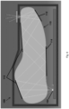
- the single optical component 110 of the illumination device 100 preferably also contains a planar surface with a selectively reflective surface 114 either incorporated into the single optical component 110 or as a separate component arranged close to or attached to the single optical component 110.
- the surface 114 may be a surface which is an image ablated metalized reflective surface, or may be a micro-optic as used in Digital Light Processing (DLP) applications.
- the surface 114 may be selectively transmissive rather than being reflective, and may be freeform rather than being planar.
- the surface 114 produces a mask that is then projected by the lamp onto the ground or to the selected projecting surface.
- the mask surface 114 replaces the mask means 18 described in other example thereby further reducing the number of components.
- the surfaces of the reflective surfaces 112 are all internally reflective.
- the incident light is below the critical angle of the material which makes a high index material preferable. This is because an internally reflective surface has very high efficiency, i.e. greater than 99%, whereas a coated surface like a mirror is significantly less efficient.
- the reflective surfaces 112 preferably do not overlap one another. As a result, the angle of reflection may range from greater than 10 degrees (change in optical path) to less than 170 degrees.
- the optical component 110 may be changed to have a more prismatic arrangement where all reflections are over 90 degrees and the shape of the optical component 110 is similar to a staircase.
- the one or more reflective surfaces 112 which are configured to receive incident light from the light source 104 prior to the mask surface 114 are for configured to capture the light from the light source 104 and focus it onto the mask surface 114.
- the one or more reflective surfaces 112 which are configured to receive incident light after the light is received by the mask surface 114 are configured to project (focus) the mask onto the projection plane.
- as many of the reflective surfaces 112 as possible are formed from a material which exhibits total internal reflection rather than refraction, and instead of being plated/painted to form a reflective surface, as described above.
- an illumination device for a vehicle component may include at least one illuminant, wherein the illuminant is adapted to emit light.
- the illumination device furthermore features a condenser unit including at least one condenser lens, wherein the condenser unit is adapted to focus the light emitted by the at least one illuminant into an optical path.
- optical path in this connection refers to the geometrical course of light beams and can also be called beam direction.
- focus refers to coupling light into an optical path, wherein as large a portion of the emitted light of the illuminant as possible is to be brought into the image-forming optical path.
- the illumination device features at least one mask means, which is arranged in the optical path and by means of which an image, symbol, logo and/or legend can be displayed on a projection surface.
- the illumination device features a lens unit having at least one objective lens, which is arranged in the optical path.
- the illumination device also features at least one reflector unit which is arranged between the condenser unit and the projection surface, wherein the reflector unit is adapted to deflect the optical path, especially essentially transversely or diagonally, to the projection surface, wherein the reflector unit includes a reflector element which includes at least one surface section by means of which the light can be deflected relative to the optical path, and wherein the surface section of the reflector element is configured as a freeform surface in order to focus the light.
- the expression “deflect transversely or diagonally to the projection surface” relates to a deflection or diversion of the optical path at an angle to the vertical to the projection surface.
- “Deflection of the optical path” can also be understood as a deflection of an optical axis.
- optical axis describes the averaged propagation direction of all beams in the image-forming optical path between successive units
- the use of the reflector unit allows the illumination device to be arranged in or on the vehicle component in a place-saving manner.
- the illumination device according to the invention does not need to be arranged exclusively vertical to a projection surface, but can also be arranged diagonally to the projection surface for example or parallel to the projection surface. This facilitates the integration of the illumination device to the extent that a particular place does not absolutely have to be provided for the illumination device, but the illumination device can rather be provided in the vehicle component at a location and with an orientation that just happens to offer adequate space for its installation.
- the reflector unit is adapted to deflect the optical path in a range of 35° to 145°, preferably of 45° to 135°, more preferably of 60° to 120°, especially by 90°.
- the at least one reflector unit is arranged along the optical path of the light, proceeding from the illuminant up to the projection surface, in front of or behind the lens unit.
- the at least one reflector unit can however also be arranged any place inside the illumination device. It is basically conceivable that the illumination device includes a plurality of reflector units. This proves advantageous particularly when the installation space available inside the vehicle component is not straight, but angular.
- the illuminant is surrounded by another reflector means in such a manner that light which is not coupled into the optical path is collected by the reflector means and coupled into the optical path. This allows the intensity of the light in the optical path and the utilization of the light emitted by the illuminant to be improved.
- the mask means is arranged along the optical path of the light, proceeding from the illuminant up to the projection surface, between the condenser unit and the lens unit.
- the reflector unit includes the mask means.
- the illumination device can be realized compactly and with reduced components if the reflector unit includes the mask means.
- the mask means and reflector unit can be included within a common component for example, or be joined in such a manner that they are undetectably or detachably connected together and can be added in as a pre-assembled subassembly of the reflector unit.
- the mask means is mechanically and/or electrically alterable or adjustable in order to change the image, symbol, logo and/or the legend that the mask means can display on the projection surface. It is also basically conceivable to prescribe that the mask means cannot change the image, symbol, logo and/or the legend that the mask means can display on the projection surface.
- the mask means can display a plurality of images or a continuous legend, for example.
- the reflector unit can basically be configured as desired.
- the reflector unit includes a lens means arranged on the reflector element and configured as a separate or separable component in order to focus the light.
- the lens means can include the condenser unit and/or the lens unit.
- the reflector unit can be implemented compactly.
- a first reflector unit includes the condenser unit and a second reflector unit includes the lens unit. This allows the number of individual components in the illumination device to be further reduced.
- the reflector unit includes both the mask means and also the condenser unit and/or the lens unit. This advantageously allows the number of components of the illumination device to be further reduced.
- the configuration of the reflector unit both as mask means and also as condenser unit and/or as lens unit is then especially advantageous when little space is available in the vehicle component to arrange the illumination device therein or thereon.
- the reflector unit includes both the mask means and also the condenser unit and/or the lens unit.
- the reflector element includes a light guide and/or a prism.
- the at least one condenser lens of the condenser unit and/or the at least one objective lens of the lens unit includes at least one tonic lens element. This thereby advantageously allows rectangular displays with high irradiance, even in corners, to be realized in a simple manner.
- the illumination device according to the invention is arranged parallel to a plane of a projection surface, then the illuminant can also emit the light essentially parallel to the projection surface.
- a diagonal emission relative to the projection surface is also conceivable.
- the at least one condenser lens of the condenser unit and/or the at least one objective lens of the lens unit can be developed fundamentally or as desired.
- the invention provides a vehicle component of a motor vehicle having at least one illumination device according to the invention.
- the vehicle component can be any component on the vehicle that is arranged so that it can enable access to the external surroundings of the motor vehicle. To this end, it can for example concern a body panel for example, a bumper device, elements of the vehicle doors and the like.
- this vehicle component can include a rearview device, like interior or exterior mirror or camera.
- the optical path of the light directly emitted by the illuminant runs essentially parallel to a driving surface. Since the optical path runs essentially parallel to the driving surface, the illumination device is essentially arranged horizontally. In addition, it is nevertheless conceivable that the illumination device is arranged running diagonally or vertically to the driving surface.
- At least one hollow space which forms a housing for the illumination device and within which the illumination device can be fixed, is configured in the vehicle component. It is basically conceivable that the illumination device is fixed on the vehicle component for example. To nevertheless be able to protect the illumination device from damage and soiling, it proves advantageous if the illumination device can be fixed within the vehicle component. In addition to protection from soiling and damage, an arrangement of the illumination device that is optically appropriate is thereby furthermore selected.
Landscapes
- Engineering & Computer Science (AREA)
- General Engineering & Computer Science (AREA)
- Physics & Mathematics (AREA)
- General Physics & Mathematics (AREA)
- Non-Portable Lighting Devices Or Systems Thereof (AREA)
- Lighting Device Outwards From Vehicle And Optical Signal (AREA)
Claims (14)
- Beleuchtungsvorrichtung (100), umfassend:mindestens ein Leuchtmittel (104) zur Lichtemission; undeine optische Reflexionseinheit (110), umfassend:mindestens eine reflektierende Fläche (112, 114); undmindestens eine Fläche (114), die mindestens eine Maske umfasst,wobei die optische Reflexionseinheit (110) dazu ausgestaltet ist, das von dem mindestens einen Leuchtmittel (104) emittierte Licht zu empfangen und ein Bild, ein Symbol, ein Logo,ein Muster und/oder eine Legende auf eine Projektionsfläche zu projizieren, dadurch gekennzeichnet, dasses sich bei der optischen Reflexionseinheit (110) um eine einzelne optische Komponente anstelle mehrerer Komponenten, die eine Mehrzahl von reflektierenden Flächen (112, 114) umfasst, handelt, wobei sich mindestens zwei reflektierende Flächen auf gegenüberliegenden Seiten der optischen Reflexionseinheit (110) befinden, wobei• das von dem mindestens einen Leuchtmittel (104) emittierte Licht dazu ausgestaltet ist, in die optische Reflexionseinheit (110) von einer ersten Seite der optischen Reflexionseinheit (110) einzutreten,• das auf die Projektionsfläche projizierte Licht dazu ausgestaltet ist, die optische Reflexionseinheit (110) von einer zweiten Seite der optischen Reflexionseinheit (110) aus zu verlassen,• eine der Mehrzahl von reflektierenden Flächen (112, 114) auf der ersten Seite und eine andere auf der zweiten Seite ausgebildet ist, und• die mindestens eine Fläche (114), die die mindestens eine Maske umfasst, auf der ersten Seite ausgebildet ist.
- Beleuchtungsvorrichtung nach Anspruch 1, wobei
die optische Reflexionseinheit (110) mindestens vier Seiten umfasst und das von dem mindestens einen Leuchtmittel (104) emittierte Licht dazu ausgestaltet ist, auf mindestens zwei der mindestens vier Seiten der optischen Reflexionseinheit (110) projiziert zu werden, bevor es auf die Projektionsfläche projiziert wird. - Beleuchtungsvorrichtung nach Anspruch 1 oder 2, wobei
die Mehrzahl von reflektierenden Flächen (112, 114) mindestens drei reflektierende Flächen umfasst, wobei sich zwei der mindestens drei reflektierenden Flächen auf derselben Seite der optischen Reflexionseinheit befinden und sich eine der mindestens drei reflektierenden Flächen auf der gegenüberliegenden Seite der optischen Reflexionseinheit befindet. - Beleuchtungsvorrichtung nach einem der vorhergehenden Ansprüche, wobei die Mehrzahl von reflektierenden Flächen (112, 114) metallisierte oder innenreflektierende Freiformoptiken umfasst, wobei vorzugsweise die mindestens eine reflektierende Fläche zumindest teilweise plan oder gekrümmt ist.
- Beleuchtungsvorrichtung nach einem der vorhergehenden Ansprüche, wobeidie mindestens eine Fläche (114), die die mindestens eine Maske umfasst, eine bildabgetragene metallisierte reflektierende Fläche und/oder eine Mikrooptik umfasst, und/oderdie mindestens eine Fläche (114), die die mindestens eine Maske umfasst, zusammen mit einer (114) der Mehrzahl von reflektierenden Flächen (112, 114) ausgebildet wird.
- Beleuchtungsvorrichtung nach einem der vorhergehenden Ansprüche, wobei die optische Reflexionseinheit (110) mindestens zwei gekrümmte Kanten und mindestens eine plane Kante umfasst, wobei die optische Reflexionseinheit vorzugsweise eine Freiformgeometrie aufweist.
- Beleuchtungsvorrichtung nach einem der vorhergehenden Ansprüche, wobei die mindestens eine Fläche (114), die die mindestens eine Maske umfasst, zusammen mit der reflektierenden Fläche (114) auf der ersten Seite ausgebildet ist.
- Beleuchtungsvorrichtung nach einem der vorhergehenden Ansprüche, wobei das von dem mindestens einen Leuchtmittel (104) emittierte Licht dazu ausgestaltet ist, eine Innenfläche der optischen Reflexionseinheit (110) mindestens viermal zu kontaktieren, bevor es auf die Projektionsfläche projiziert wird.
- Beleuchtungsvorrichtung nach einem der vorhergehenden Ansprüche, wobei die mindestens eine reflektierende Fläche (112, 114) dazu ausgestaltet ist, den optischen Weg in mindestens einem Bereiche 35° bis 145°, 45° bis 135°, 60° bis 120° und/oder etwa 90° abzulenken.
- Beleuchtungsvorrichtung nach einem der vorhergehenden Ansprüche, wobei es sich bei der mindestens einen Maske zumindest um eine mechanisch und/oder elektrisch veränderbare oder anpassbare Maske handelt, um das Bild, das Symbol, das Logo und/oder die Legende zu ändern, für dessen/deren Anzeige auf der Projektionsfläche die Maske ausgestaltet ist.
- Beleuchtungsvorrichtung nach einem der vorhergehenden Ansprüche, wobei das Leuchtmittel das Licht in einem Winkel zwischen etwa 0 Grad und etwa 20 Grad in Bezug auf eine normale Achse der Projektionsfläche emittiert.
- Fahrzeugeinheit eines Kraftfahrzeugs in Form eines Innen- oder Außenspiegels oder einer Kamera, die mindestens eine Beleuchtungsvorrichtung nach einem der vorhergehenden Ansprüche umfasst.
- Fahrzeugeinheit nach Anspruch 12, wobei
die mindestens eine Beleuchtungsvorrichtung eine Logolampe bereitstellt, die dazu ausgelegt ist, zumindest in Bezug auf das Fahrzeug beweglich und/oder an der Außenseite des Fahrzeugs anbringbar zu sein. - Kraftfahrzeug, das mindestens eine Fahrzeugeinheit gemäß Anspruch 12 oder 13 umfasst.
Applications Claiming Priority (1)
| Application Number | Priority Date | Filing Date | Title |
|---|---|---|---|
| US16/181,917 US10391933B2 (en) | 2015-09-15 | 2018-11-06 | Illumination apparatus, vehicle component and vehicle |
Publications (2)
| Publication Number | Publication Date |
|---|---|
| EP3650933A1 EP3650933A1 (de) | 2020-05-13 |
| EP3650933B1 true EP3650933B1 (de) | 2025-01-01 |
Family
ID=68426228
Family Applications (1)
| Application Number | Title | Priority Date | Filing Date |
|---|---|---|---|
| EP19206767.6A Active EP3650933B1 (de) | 2018-11-06 | 2019-11-01 | Beleuchtungsvorrichtung, fahrzeugkomponente und fahrzeug |
Country Status (2)
| Country | Link |
|---|---|
| EP (1) | EP3650933B1 (de) |
| CN (1) | CN111207363B (de) |
Families Citing this family (3)
| Publication number | Priority date | Publication date | Assignee | Title |
|---|---|---|---|---|
| DE102023117081A1 (de) | 2023-06-28 | 2025-01-02 | Audi Aktiengesellschaft | Anzeigesystem |
| CN116909079B (zh) * | 2023-09-14 | 2023-12-05 | 华域视觉科技(上海)有限公司 | 车辆投影模组、车辆及车辆投影模组的控制方法 |
| CN120062572A (zh) * | 2023-11-22 | 2025-05-30 | 深圳引望智能技术有限公司 | 一种智能车灯及汽车 |
Family Cites Families (13)
| Publication number | Priority date | Publication date | Assignee | Title |
|---|---|---|---|---|
| KR100400543B1 (ko) * | 2001-03-17 | 2003-10-08 | 엘지전자 주식회사 | 광 기록 및 재생 시스템용 렌즈 |
| DE10134594A1 (de) | 2001-07-17 | 2003-01-30 | Bayerische Motoren Werke Ag | Beleuchtungssystem und Beleuchtungsverfahren |
| US20030038928A1 (en) * | 2001-08-27 | 2003-02-27 | Alden Ray M. | Remote image projector for hand held and wearable applications |
| DE102004050600A1 (de) | 2004-10-15 | 2006-04-20 | Daimlerchrysler Ag | Beleuchtungseinrichtung für ein Fahrzeug |
| DE102006057671A1 (de) | 2006-12-07 | 2008-06-12 | Daimler Ag | Lichtdurchlässige Komponente für eine Kraftfahrzeugleuchte |
| DE102008003451A1 (de) * | 2007-08-08 | 2009-02-12 | Osram Opto Semiconductors Gmbh | Abbildungseinrichtung |
| EP2072336B1 (de) | 2007-12-21 | 2013-03-06 | SMR Patents S.à.r.l. | Näherungslicht mit Lichtmuster |
| DE202008016695U1 (de) | 2008-12-17 | 2009-02-26 | Visiocorp Patents S.á.r.l. | Umfeldleuchte mit Logo |
| US10220770B2 (en) * | 2011-07-08 | 2019-03-05 | Sl Corporation | Guide lamp for vehicle |
| DE102012024494A1 (de) * | 2012-12-14 | 2014-06-18 | Audi Ag | Flurförderzeug mit einer optischen Warneinrichtung, Kraftfahrzeug mit einer optischen Warneinrichtung und Projektor zur Verwendung als optische Warneinrichtung |
| JP6131724B2 (ja) | 2013-06-11 | 2017-05-24 | スタンレー電気株式会社 | 車両用灯具 |
| JP6270033B2 (ja) | 2014-02-17 | 2018-01-31 | スタンレー電気株式会社 | 車両用灯具 |
| JP6499632B2 (ja) * | 2016-12-07 | 2019-04-10 | スタンレー電気株式会社 | 車両用灯具 |
-
2019
- 2019-11-01 EP EP19206767.6A patent/EP3650933B1/de active Active
- 2019-11-06 CN CN201911075657.3A patent/CN111207363B/zh active Active
Non-Patent Citations (1)
| Title |
|---|
| HO HUH YOON ET AL: "Power generating reflective-type liquid crystal displays using a reflective polariser and a polymer solar cell", SCIENTIFIC REPORTS, vol. 5, no. 1, 1 September 2015 (2015-09-01), XP055954551, Retrieved from the Internet <URL:https://www.nature.com/articles/srep11558.pdf> DOI: 10.1038/srep11558 * |
Also Published As
| Publication number | Publication date |
|---|---|
| EP3650933A1 (de) | 2020-05-13 |
| CN111207363B (zh) | 2023-01-20 |
| CN111207363A (zh) | 2020-05-29 |
Similar Documents
| Publication | Publication Date | Title |
|---|---|---|
| US10246007B2 (en) | Illumination apparatus, vehicle component and vehicle | |
| US9348140B2 (en) | Virtual image display device | |
| US12222077B2 (en) | Vehicle external illumination device | |
| CN104121535B (zh) | 用于机动车前大灯的光模块 | |
| EP3650933B1 (de) | Beleuchtungsvorrichtung, fahrzeugkomponente und fahrzeug | |
| JP6601438B2 (ja) | ヘッドアップディスプレイ装置 | |
| US10690911B2 (en) | Projection optical system and head-up display device | |
| EP3521898B1 (de) | Reflektierende platte, informationsanzeigevorrichtung und beweglicher körper | |
| EP3415973B1 (de) | Anzeigevorrichtung und head-up-anzeige | |
| US20060232853A1 (en) | Projection unit for a head-up display | |
| JP7000937B2 (ja) | 表示装置及び機器 | |
| US10391933B2 (en) | Illumination apparatus, vehicle component and vehicle | |
| US11561396B2 (en) | Head-up display device and transportation device | |
| JPWO2018066062A1 (ja) | 投影光学系、及びヘッドアップディスプレイ装置 | |
| US10760760B2 (en) | Illumination apparatus, vehicle component and vehicle | |
| JP7367525B2 (ja) | 表示装置、表示システムおよび移動体 | |
| US12554144B2 (en) | Optics for slim style head lighting | |
| WO2005024508A1 (ja) | 複数視野撮影用光路折り曲げ器、複数視野撮影装置、三視野撮影用光路折り曲げ器および三視野撮影装置 | |
| US6873470B2 (en) | Arrangement for the visualization of information in a motor vehicle | |
| WO2020226129A1 (ja) | 車両用灯具 | |
| Li et al. | Single DMD intelligent headlight with lidar | |
| KR20250121341A (ko) | 지향성 광학 디바이스 | |
| CN121878985A (zh) | 平视显示装置 | |
| CN121828636A (zh) | 光模块、用于操作光模块的方法及机动车辆 | |
| JP2004138668A (ja) | 投影型表示装置 |
Legal Events
| Date | Code | Title | Description |
|---|---|---|---|
| PUAI | Public reference made under article 153(3) epc to a published international application that has entered the european phase |
Free format text: ORIGINAL CODE: 0009012 |
|
| STAA | Information on the status of an ep patent application or granted ep patent |
Free format text: STATUS: THE APPLICATION HAS BEEN PUBLISHED |
|
| AK | Designated contracting states |
Kind code of ref document: A1 Designated state(s): AL AT BE BG CH CY CZ DE DK EE ES FI FR GB GR HR HU IE IS IT LI LT LU LV MC MK MT NL NO PL PT RO RS SE SI SK SM TR |
|
| AX | Request for extension of the european patent |
Extension state: BA ME |
|
| RIN1 | Information on inventor provided before grant (corrected) |
Inventor name: MESSENGER, JACOB Inventor name: FRITZ, DANIEL Inventor name: SCHMIDT, OLIVER |
|
| STAA | Information on the status of an ep patent application or granted ep patent |
Free format text: STATUS: REQUEST FOR EXAMINATION WAS MADE |
|
| RIN1 | Information on inventor provided before grant (corrected) |
Inventor name: SCHMIDT, OLIVER Inventor name: FRITZ, DANIEL Inventor name: MESSENGER, JACOB |
|
| 17P | Request for examination filed |
Effective date: 20201111 |
|
| RBV | Designated contracting states (corrected) |
Designated state(s): AL AT BE BG CH CY CZ DE DK EE ES FI FR GB GR HR HU IE IS IT LI LT LU LV MC MK MT NL NO PL PT RO RS SE SI SK SM TR |
|
| STAA | Information on the status of an ep patent application or granted ep patent |
Free format text: STATUS: EXAMINATION IS IN PROGRESS |
|
| 17Q | First examination report despatched |
Effective date: 20210128 |
|
| P01 | Opt-out of the competence of the unified patent court (upc) registered |
Effective date: 20230616 |
|
| GRAP | Despatch of communication of intention to grant a patent |
Free format text: ORIGINAL CODE: EPIDOSNIGR1 |
|
| STAA | Information on the status of an ep patent application or granted ep patent |
Free format text: STATUS: GRANT OF PATENT IS INTENDED |
|
| RAP3 | Party data changed (applicant data changed or rights of an application transferred) |
Owner name: SMR PATENTS S.A.R.L. |
|
| INTG | Intention to grant announced |
Effective date: 20240718 |
|
| GRAS | Grant fee paid |
Free format text: ORIGINAL CODE: EPIDOSNIGR3 |
|
| GRAA | (expected) grant |
Free format text: ORIGINAL CODE: 0009210 |
|
| STAA | Information on the status of an ep patent application or granted ep patent |
Free format text: STATUS: THE PATENT HAS BEEN GRANTED |
|
| AK | Designated contracting states |
Kind code of ref document: B1 Designated state(s): AL AT BE BG CH CY CZ DE DK EE ES FI FR GB GR HR HU IE IS IT LI LT LU LV MC MK MT NL NO PL PT RO RS SE SI SK SM TR |
|
| REG | Reference to a national code |
Ref country code: GB Ref legal event code: FG4D |
|
| REG | Reference to a national code |
Ref country code: CH Ref legal event code: EP |
|
| REG | Reference to a national code |
Ref country code: DE Ref legal event code: R096 Ref document number: 602019064175 Country of ref document: DE |
|
| REG | Reference to a national code |
Ref country code: IE Ref legal event code: FG4D |
|
| REG | Reference to a national code |
Ref country code: LT Ref legal event code: MG9D |
|
| REG | Reference to a national code |
Ref country code: NL Ref legal event code: MP Effective date: 20250101 |
|
| REG | Reference to a national code |
Ref country code: AT Ref legal event code: MK05 Ref document number: 1756856 Country of ref document: AT Kind code of ref document: T Effective date: 20250101 |
|
| PG25 | Lapsed in a contracting state [announced via postgrant information from national office to epo] |
Ref country code: NL Free format text: LAPSE BECAUSE OF FAILURE TO SUBMIT A TRANSLATION OF THE DESCRIPTION OR TO PAY THE FEE WITHIN THE PRESCRIBED TIME-LIMIT Effective date: 20250101 |
|
| PG25 | Lapsed in a contracting state [announced via postgrant information from national office to epo] |
Ref country code: FI Free format text: LAPSE BECAUSE OF FAILURE TO SUBMIT A TRANSLATION OF THE DESCRIPTION OR TO PAY THE FEE WITHIN THE PRESCRIBED TIME-LIMIT Effective date: 20250101 |
|
| PG25 | Lapsed in a contracting state [announced via postgrant information from national office to epo] |
Ref country code: PL Free format text: LAPSE BECAUSE OF FAILURE TO SUBMIT A TRANSLATION OF THE DESCRIPTION OR TO PAY THE FEE WITHIN THE PRESCRIBED TIME-LIMIT Effective date: 20250101 |
|
| PG25 | Lapsed in a contracting state [announced via postgrant information from national office to epo] |
Ref country code: ES Free format text: LAPSE BECAUSE OF FAILURE TO SUBMIT A TRANSLATION OF THE DESCRIPTION OR TO PAY THE FEE WITHIN THE PRESCRIBED TIME-LIMIT Effective date: 20250101 |
|
| PG25 | Lapsed in a contracting state [announced via postgrant information from national office to epo] |
Ref country code: IS Free format text: LAPSE BECAUSE OF FAILURE TO SUBMIT A TRANSLATION OF THE DESCRIPTION OR TO PAY THE FEE WITHIN THE PRESCRIBED TIME-LIMIT Effective date: 20250501 Ref country code: NO Free format text: LAPSE BECAUSE OF FAILURE TO SUBMIT A TRANSLATION OF THE DESCRIPTION OR TO PAY THE FEE WITHIN THE PRESCRIBED TIME-LIMIT Effective date: 20250401 |
|
| PG25 | Lapsed in a contracting state [announced via postgrant information from national office to epo] |
Ref country code: HR Free format text: LAPSE BECAUSE OF FAILURE TO SUBMIT A TRANSLATION OF THE DESCRIPTION OR TO PAY THE FEE WITHIN THE PRESCRIBED TIME-LIMIT Effective date: 20250101 |
|
| PG25 | Lapsed in a contracting state [announced via postgrant information from national office to epo] |
Ref country code: PT Free format text: LAPSE BECAUSE OF FAILURE TO SUBMIT A TRANSLATION OF THE DESCRIPTION OR TO PAY THE FEE WITHIN THE PRESCRIBED TIME-LIMIT Effective date: 20250502 Ref country code: LV Free format text: LAPSE BECAUSE OF FAILURE TO SUBMIT A TRANSLATION OF THE DESCRIPTION OR TO PAY THE FEE WITHIN THE PRESCRIBED TIME-LIMIT Effective date: 20250101 |
|
| PG25 | Lapsed in a contracting state [announced via postgrant information from national office to epo] |
Ref country code: BG Free format text: LAPSE BECAUSE OF FAILURE TO SUBMIT A TRANSLATION OF THE DESCRIPTION OR TO PAY THE FEE WITHIN THE PRESCRIBED TIME-LIMIT Effective date: 20250101 Ref country code: GR Free format text: LAPSE BECAUSE OF FAILURE TO SUBMIT A TRANSLATION OF THE DESCRIPTION OR TO PAY THE FEE WITHIN THE PRESCRIBED TIME-LIMIT Effective date: 20250402 |
|
| PG25 | Lapsed in a contracting state [announced via postgrant information from national office to epo] |
Ref country code: AT Free format text: LAPSE BECAUSE OF FAILURE TO SUBMIT A TRANSLATION OF THE DESCRIPTION OR TO PAY THE FEE WITHIN THE PRESCRIBED TIME-LIMIT Effective date: 20250101 |
|
| PG25 | Lapsed in a contracting state [announced via postgrant information from national office to epo] |
Ref country code: CZ Free format text: LAPSE BECAUSE OF FAILURE TO SUBMIT A TRANSLATION OF THE DESCRIPTION OR TO PAY THE FEE WITHIN THE PRESCRIBED TIME-LIMIT Effective date: 20250101 |
|
| PG25 | Lapsed in a contracting state [announced via postgrant information from national office to epo] |
Ref country code: SE Free format text: LAPSE BECAUSE OF FAILURE TO SUBMIT A TRANSLATION OF THE DESCRIPTION OR TO PAY THE FEE WITHIN THE PRESCRIBED TIME-LIMIT Effective date: 20250101 |
|
| REG | Reference to a national code |
Ref country code: DE Ref legal event code: R097 Ref document number: 602019064175 Country of ref document: DE |
|
| PG25 | Lapsed in a contracting state [announced via postgrant information from national office to epo] |
Ref country code: SM Free format text: LAPSE BECAUSE OF FAILURE TO SUBMIT A TRANSLATION OF THE DESCRIPTION OR TO PAY THE FEE WITHIN THE PRESCRIBED TIME-LIMIT Effective date: 20250101 |
|
| PG25 | Lapsed in a contracting state [announced via postgrant information from national office to epo] |
Ref country code: DK Free format text: LAPSE BECAUSE OF FAILURE TO SUBMIT A TRANSLATION OF THE DESCRIPTION OR TO PAY THE FEE WITHIN THE PRESCRIBED TIME-LIMIT Effective date: 20250101 |
|
| PG25 | Lapsed in a contracting state [announced via postgrant information from national office to epo] |
Ref country code: IT Free format text: LAPSE BECAUSE OF FAILURE TO SUBMIT A TRANSLATION OF THE DESCRIPTION OR TO PAY THE FEE WITHIN THE PRESCRIBED TIME-LIMIT Effective date: 20250101 |
|
| PG25 | Lapsed in a contracting state [announced via postgrant information from national office to epo] |
Ref country code: EE Free format text: LAPSE BECAUSE OF FAILURE TO SUBMIT A TRANSLATION OF THE DESCRIPTION OR TO PAY THE FEE WITHIN THE PRESCRIBED TIME-LIMIT Effective date: 20250101 |
|
| PG25 | Lapsed in a contracting state [announced via postgrant information from national office to epo] |
Ref country code: RO Free format text: LAPSE BECAUSE OF FAILURE TO SUBMIT A TRANSLATION OF THE DESCRIPTION OR TO PAY THE FEE WITHIN THE PRESCRIBED TIME-LIMIT Effective date: 20250101 |
|
| PG25 | Lapsed in a contracting state [announced via postgrant information from national office to epo] |
Ref country code: SK Free format text: LAPSE BECAUSE OF FAILURE TO SUBMIT A TRANSLATION OF THE DESCRIPTION OR TO PAY THE FEE WITHIN THE PRESCRIBED TIME-LIMIT Effective date: 20250101 |
|
| PLBE | No opposition filed within time limit |
Free format text: ORIGINAL CODE: 0009261 |
|
| STAA | Information on the status of an ep patent application or granted ep patent |
Free format text: STATUS: NO OPPOSITION FILED WITHIN TIME LIMIT |
|
| 26N | No opposition filed |
Effective date: 20251002 |
|
| PGFP | Annual fee paid to national office [announced via postgrant information from national office to epo] |
Ref country code: DE Payment date: 20251118 Year of fee payment: 7 |
|
| PGFP | Annual fee paid to national office [announced via postgrant information from national office to epo] |
Ref country code: GB Payment date: 20251120 Year of fee payment: 7 |
|
| PGFP | Annual fee paid to national office [announced via postgrant information from national office to epo] |
Ref country code: FR Payment date: 20251120 Year of fee payment: 7 |